Embed Size (px)
Citation preview
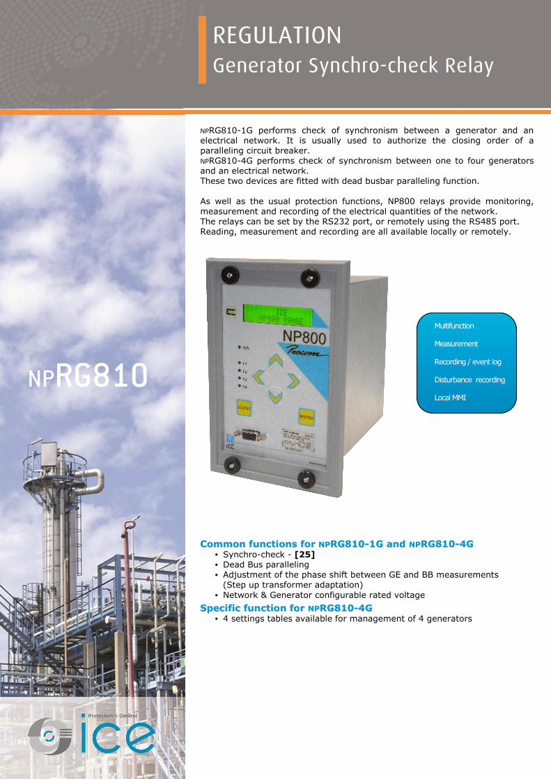
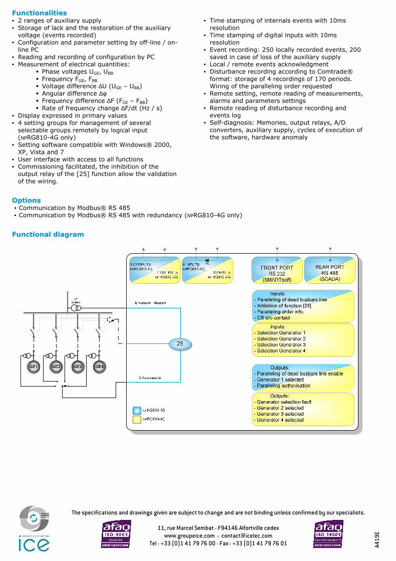
NPRG810-1G performs check of synchronism between a generator and an electrical network. It is usually used to authorize the closing order of a paralleling circuit breaker. NPRG810-4G performs check of synchronism between one to four generators and an electrical network. These two devices are fitted with dead busbar paralleling function. As well as the usual protection functions, NP800 relays provide monitoring, measurement and recording of the electrical quantities of the network. The relays can be set by the RS232 port, or remotely using the RS485 port. Reading, measurement and recording are all available locally or remotely.
CCoommmmoonn ffuunnccttiioonnss ffoorr NNPPRRGG881100--11GG aanndd NNPPRRGG881100--44GG • Synchro-check - [25] • Dead Bus paralleling • Adjustment of the phase shift between GE and BB measurements
(Step up transformer adaptation) • Network & Generator configurable rated voltage
SSppeecciiffiicc ffuunnccttiioonn ffoorr NNPPRRGG881100--44GG • 4 settings tables available for management of 4 generators
NPRG810
Multifunction Measurement Recording / event log Disturbance recording Local MMI
REGULATION Generator Synchro-check Relay

CCHHAARRAACCTTEERRIISSTTIICCSS NNPPRRGG881100
AAuuxxiilliiaarryy SSuuppppllyy • Auxiliary supply ranges 19 to 70 – 85 to 255 / Vdc or Vac 50 or 60 Hz • Typical burden 6 W (CC), 6 VA (CA) • Memory backup 72 hours
AAnnaalloogguuee IInnppuuttss • Phase voltage inputs Un: 55 to 120 V input impedance > 80 KΩ continuous rating 240 V, short duration withstand 275V - 1 min measurement from 3 to 240 V VT setting: primary value from 100 V to 30 kV • Frequency (50Hz or 60Hz) measurement: 45-55 Hz or 55-65 Hz measurement: 30-70 Hz (from V1.50)
DDiiggiittaall IInnppuuttss ((44 ffoorr NNPPRRGG881100--11GG,, 88 ffoorr NNPPRRGG881100--44GG)) • Polarizing voltage 20 to 70 Vdc, range 19 to 70 V 37 to 140 Vdc, range 85 to 255 V • Level 0 < 10Vdc range 19 to 70 V – < 33Vdc range 85 to 255 V • Level 1 > 20Vdc range 19 to 70 V – > 37Vdc range 85 to 255 V • Burden < 15 mA
RReellaayy OOuuttppuuttss ((22** ffoorr NNPPRRGG881100--11GG ++ 11 WWDD,, 77 ffoorr NNPPRRGG881100--44GG ++ 11 WWDD)) • Relays A*, B, E, F double contact NO, permanent current 8 A closing capacity 12 A / 4 s short circuit current withstand 100 A / 30 ms breaking capacity DC with L/R = 40 ms: 50 W breaking capacity AC with cos φ = 0.4: 1250 VA • Relays C*, WD, D, G changeover contact, permanent current 16 A closing capacity 25 A / 4 s short circuit current withstand 250 A / 30 ms breaking capacity DC with L/R = 40 ms: 50 W breaking capacity AC with cos φ = 0.4: 1250 VA
CChhaarraacctteerriissttiiccss ooff tthhee ffuunnccttiioonn [[2255]] • Blocking of the output relay C possible by digital input (output relay use for paralleling authorisation) • Threshold U GE mini for authorisation [25] 50 to 100 % Un • Threshold accuracy 2% of Un • Setting of voltage difference: ∆U thresholds +/- : 1% to 15% Un, with step of 1% Un • Voltage difference accuracy ± 5% of the set value • Setting of angular difference: ∆ϕ thresholds +/- : 1° to 20°, with step of 1° • Angular difference accuracy ± 2% • Setting of frequency difference: ∆F thresholds +/- : 0.01 to 1.5 Hz, with step of 0.01 Hz • Frequency difference accuracy ± 5% of the set value • Setting of rate of frequency change: thresholds +/- : 0.01 to 0.2 Hz/s, with step of 0.01 Hz/s ∆F/dt • Rate of frequency change accuracy ± 2% • Time lag before authorisation 0 ms to 1 s, with step of 0.1 s • Accuracy of the time delays ± 2% or 20 ms • Accuracy of displayed measures 3% from 3 to 240 V
DDeeaadd BBuuss ppaarraalllleelliinngg • Dead busbar paralleling enabled by dedicated DI or setting software • Info dead busbar paralleling enabled HMI, dedicated DI, communication and setting software • Busbar voltage detection threshold 10% to 50% Un, with step of 1% Un • Threshold accuracy 2% of Un • Setting of frequency difference thresholds F< and F>: 0 to 1 Hz, with step of 0.1 Hz • Angular accuracy / frequency difference ± 2% • Setting of voltage difference thresholds U< and U>: 1 to 10% Un, with step of 1% Un • Voltage difference accuracy ± 5% of the set value • Time lag before paralleling 1 to 5 s, with step of 0.5 s • Accuracy of the time delay ± 2% or 20 ms
AAddjjuussttmmeenntt ooff tthhee pphhaassee sshhiifftt bbeettwweeeenn GGEE aanndd BBBB mmeeaassuurreemmeennttss • GE voltage / BB voltage 0 to 360°, with step of 1°
CCHHAARRAACCTTEERRIISSTTIICCSS NNPPRRGG881100
DDiiggiittaall iinnppuuttss aassssiiggnnmmeenntt ((sseeee aapppplliiccaattiioonn gguuiiddee)) • Input 1 paralleling of dead bus line • Input 2 inhibition of the function [25] • Input 3 paralleling order (management of disturbance recording and events) • Input 4 contact o/o of the Circuit Breaker (management of events) • Input 5 (NPRG810-4g only) selection generator 1 • Input 6 (NPRG810-4g only) selection generator 2 • Input 7 (NPRG810-4g only) selection generator 3 • Input 8 (NPRG810-4g only) selection generator 4
DDiiggiittaall oouuttppuutt aassssiiggnnmmeenntt ((sseeee aapppplliiccaattiioonn gguuiiddee)) • Relay A paralleling of dead bus line enable • Relay B (NPRG810-4G only) generator 1 selected • Relay C paralleling authorisation (permanent order if conditions are valid) • Relay D (NPRG810-4G only) generator selection fault • Relay E (NPRG810-4G only) generator 2 selected • Relay F (NPRG810-4G only) generator 3 selected • Relay G (NPRG810-4G only ) generator 4 selected
SSiiggnnaalllliinngg LLEEDDss aassssiiggnnmmeenntt • LED 1 info ∆U OK • LED 2 info ∆ϕ OK • LED 3 info ∆F OK • LED 4 paralleling authorised
SSeettttiinngg • Display French, English, Spanish, Italian • Configuration and operating software Windows® compatible 2000, XP, Vista and 7 French, English, Spanish, Italian
MMOODDBBUUSS®® CCoommmmuunniiccaattiioonn ((ooppttiioonn)) • Transmission asynchronous series, 2 wires • Interface RS 485 • Transmission speed 300 to 115 200 bauds
DDiissttuurrbbaannccee rreeccoorrddiinngg • Number of recordings 4 • Total duration 170 cycles per recording (12 samples / cycle) • Pre fault time adjustable from 0 to 170 cycles
CClliimmaattiicc wwiitthhssttaanndd iinn ooppeerraattiioonn • Cold exposure IEC / EN 60068-2-1: class Ad, -10 °C • Dry heat exposure IEC / EN 60068-2-2: class Bd, +55 °C • Damp heat exposure IEC / EN 60068-2-3: class Ca, 93 % HR, 40 °C, 56 days • Temperature variation with specified IEC / EN 60068-2-14: class Nb, -10 °C à +55 °C, 3 °C/min variation rate
SSttoorraaggee • Cold exposure IEC / EN 60068-2-1: class Ad, -25 °C • Dry heat exposure IEC / EN 60068-2-2: class Bd, +70 °C
EElleeccttrriiccaall ssaaffeettyy • Ground bond test current IEC / EN 61010-1: 30 A • Impulse voltage withstand IEC / EN 60255-5: 5 kV MC, 5 kV MD except outputs TOR, 1 kV MD except RS485, 3 kV MC
• Dielectric withstand: 50Hz IEC / EN 60255-5: common mode 2 kVrms – 1 min Differential outputs mode TOR 1 kVrms – 1 min (open contact type) • Insulation resistance IEC / EN 60255-5: 500 Vdc - 1 s: > 100 MΩ • Clearance and creepage distances IEC / EN 60255-5: rated insulation voltage: 250 V Pollution degree: 2 Overvoltage category: III
CCHHAARRAACCTTEERRIISSTTIICCSS NNPPRRGG881100
EEnncclloossuurree ssaaffeettyy • Degrees of protection provided by IEC / EN 60529: IP51, with front face enclosures (IP code)
IImmmmuunniittyy –– CCoonndduucctteedd ddiissttuurrbbaanncceess • Immunity to RF conducted disturbances IEC / EN 61000-4-6: class III, 10 V • Fast transients IEC / EN 60255-22-4 / IEC / EN 61000-4-4: class IV • Oscillatory waves disturbance 1 MHz IEC / EN 60255-22-1: class III, 2.5 kV MC, 1 kV MD except RS485, class II, 1 kV MC • Surge immunity IEC / EN 61000-4-5: class III • Supply interruptions IEC / EN 60255-11: 100% 20 ms
IImmmmuunniittyy –– RRaaddiiaatteedd ddiissttuurrbbaanncceess • Immunity to RF radiated fields IEC / EN 60255-22-3 / IEC / EN 61000-4-3: class III, 10 V/m • Electrostatic discharges IEC / EN 60255-22-2 / IEC / EN 61000-4-2: class III, 8 kV air / 6 kV contact • Power frequency magnetic field IEC / EN 61000-4-8: class IV, 30 A/m permanent, 300 A/m immunity test 1 to 3 s
MMeecchhaanniiccaall rroobbuussttnneessss -- eenneerrggiisseedd • Vibrations IEC / EN 60255-21-1: class 1, 0.5 Gn • Shocks IEC / EN 60255-21-2: class 1, 5 Gn / 11 ms
MMeecchhaanniiccaall rroobbuussttnneessss -- nnoott eenneerrggiisseedd • Vibrations IEC / EN 60255-21-1: class 1, 1 Gn • Shocks IEC / EN 60255-21-2: class 1, 15 Gn / 11 ms • Bumps IEC / EN 60255-21-2: class 1, 10 Gn / 16 ms • Free falls IEC / EN 60068-2-32: class 1, 250 mm
EElleeccttrroommaaggnneettiicc ccoommppaattiibbiilliittyy ((EEMMCC)) • Radiated field emissivity EN 55022: class A • Conducted disturbance emissivity EN 55022: class A
PPrreesseennttaattiioonn • Height 4U • Width ¼ 19" • Brackets 19” rack mounting option (see drawing D37739) • Display 2 lines of 16 characters
CCaassee • H, W, D without connectors 173 x 106.3 x 250 mm (see drawing D37739) • Net weight 3.6 kg
CCoonnnneeccttiioonn -- ccooddiiffiiccaattiioonn • NPRG810-1G see diagram S39371 • NPRG810-4G see diagram S39610
CCHHAARRAACCTTEERRIISSTTIICCSS NNPPRRGG881100
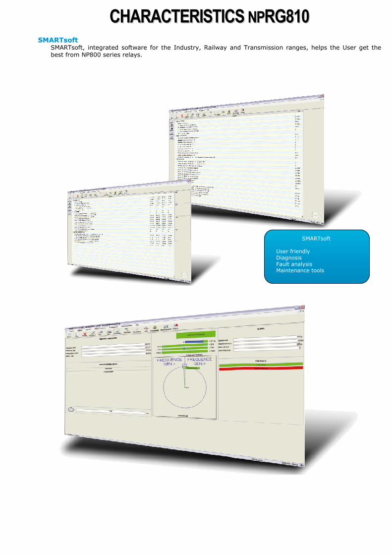
SSMMAARRTTssoofftt SMARTsoft, integrated software for the Industry, Railway and Transmission ranges, helps the User get the best from NP800 series relays.
SMARTsoft User friendly Diagnosis Fault analysis Maintenance tools
The specifications and drawings given are subject to change and are not binding unless confirmed by our specialists.
11, rue Marcel Sembat - F94146 Alfortville cedex www.groupeice.com - [email protected]
Tel : +33 (0)1 41 79 76 00 - Fax : +33 (0)1 41 79 76 01 A4
19
E
FFuunnccttiioonnaalliittiieess • 2 ranges of auxiliary supply • Storage of lack and the restoration of the auxiliary
voltage (events recorded) • Configuration and parameter setting by off-line / on-
line PC • Reading and recording of configuration by PC • Measurement of electrical quantities:
Phase voltages UGE, UBB Frequency FGE, FBB Voltage difference ∆U (UGE – UBB) Angular difference ∆φ Frequency difference ∆F (FGE – FBB) Rate of frequency change ∆F/dt (Hz / s)
• Display expressed in primary values • 4 setting groups for management of several
selectable groups remotely by logical input (NPRG810-4G only)
• Setting software compatible with Windows® 2000, XP, Vista and 7
• User interface with access to all functions • Commissioning facilitated, the inhibition of the
output relay of the [25] function allow the validation of the wiring.
• Time stamping of internals events with 10ms
resolution • Time stamping of digital inputs with 10ms
resolution • Event recording: 250 locally recorded events, 200
saved in case of loss of the auxiliary supply • Local / remote events acknowledgment • Disturbance recording according to Comtrade®
format: storage of 4 recordings of 170 periods. Wiring of the paralleling order requested
• Remote setting, remote reading of measurements, alarms and parameters settings
• Remote reading of disturbance recording and events log
• Self-diagnosis: Memories, output relays, A/D converters, auxiliary supply, cycles of execution of the software, hardware anomaly
OOppttiioonnss • Communication by Modbus® RS 485 • Communication by Modbus® RS 485 with redundancy (NPRG810-4G only)
FFuunnccttiioonnaall ddiiaaggrraamm