Embed Size (px)
Citation preview

Eindrapport
ScopingstudievoorintegratieGeoTOPenBIM
Alsinputvoordeontwikkelingvan
BasisRegistratieOndergrond
Juni2017 Inopdrachtvan:
Door:AbdoulayeDiakitéM.m.v.:JantienStoter

TableofContent1. Introduction.....................................................................................................................31.1Motivation......................................................................................................................31.2Aimandscopeofthisproject.........................................................................................31.3Overviewofthisreport..................................................................................................4
2. GeoTOPdata....................................................................................................................52.1Generalities:...................................................................................................................52.2VoxelmodelandNetCDF:..............................................................................................5
3. BIMtoolsandrelatedopenstandard..............................................................................74. OurSolution.....................................................................................................................85. ImplementationandResults..........................................................................................105.1Inputdata.....................................................................................................................105.2Outputdata:IfcSpacevoxels........................................................................................11
6. Issues..............................................................................................................................136.1Modelalignmentissues................................................................................................136.2Georeferencing.............................................................................................................14
7. Conclusionsandrecommendations...............................................................................16References..............................................................................................................................18Appendix1.............................................................................................................................19

1. Introduction
1.1MotivationData about the geological subsurface provide important information about the conditions of the ground. Such data is of critical interest for any project involving shallow or deep digging of the ground, such as building construction, excavation, etc. By taking into account such information at the design stage, risks of accidents can be better handled and costs can be reduced significantly. The Netherlands possesses a wide range of information about the subsurface, and most of them are open data. The Netherlands Organisation for Applied Scientific Research (TNO), through its branch in charge of geological survey, Geologische Dienst Nederland (GDN), has made available the largest databank on the ground beneath the Netherlands. This databank, known by the acronym DINO, is the single clearinghouse for geo data on the shallow and deep geology of the Netherlands. It comprises borehole data, groundwater data, cone penetration test data, vertical electrical soundings, the results of geological, chemical and mechanical sample analyses, borehole logs and seismic data (DINOloket, 2017a). However, despite the availability of the subsurface data in the Netherlands as open data for years, the data is hardly used in the design and planning phase of major infrastructure projects. This may be due to the fact that the teams involved in those projects are not aware of the availability of such data. This could also be explained by incompatibilities between the formats in which the data are encoded and delivered by TNO, and the tools that are used by designers of infrastructure projects. 1.2AimandscopeofthisprojectThe subsurface data is an important part of the currently being established BRO (Basis Registratie Ondergrond). The aim of the BRO is that subsurface information can easily be used in applications that can benefit from these data. To provide input for optimal development of the BRO, the project presented in this report, examined how information about the subsurface can be made more accessible to designers and how the BRO can be developed accordingly. The project was carried out by the 3D Geoinformation research group at Delft University of Technology, commissioned by the Ministry of Infrastructure and Environment between December 2016 and May 2017. The subsurface data that is investigated here is the GeoTOP data, a countrywide data set on the geological composition of the shallow subsurface. It is disseminated under the NetCDF (Network Common Data Form) format and available on an online server. On the design side, projects relying on the Building Information Modelling (BIM) paradigm are targeted, as well as the tools (software) allowing to design these projects. Our goal is to develop an interface between GeoTOP and construction/design applications so that the latter can easily check and eventually integrate such data to their workflow. The focus is put as much as possible on solutions based on open standards to maximize the interoperability possibilities. It may appear that tailored commercial solutions may improve the usability of the data. These should be developed upon the open standards.

In addition to a prototype of the interface, this project aims to also understand how the surface data can be accessed the best in the design phase and what next steps are needed to achieve this. The recommendations will be formulated in the form of action points that can be addressed in a follow up project. 1.3OverviewofthisreportThis report is organised as follows. First the details of GeoTOP are described in chapter 2. Then the tools and open standards that are common to the BIM domain are described in chapter 3. Our developed solution to disclose GeoTOP for the BIM domain is presented in chapter 4. Chapter 5 describes the implementation and results. The issues that we encountered usefull for further development of the open standard solution are described in chapter 6. And chapter 7 closes with conclusions and recommendations. The code that is developed in this small project is available on Github: https://github.com/tudelft3d/subim

2. GeoTOPdata 2.1Generalities:The 3D voxel model GeoTOP schematizes onshore Netherlands in millions of voxels, each measuring 100 x 100 x 0.5 m, to a depth of 50 m below NAP (Dutch Ordnance Level). It provides information on the stratigraphy, lithology and the interrelated physical and chemical properties of the subsurface. (DINOloket, 2017b)
Figure 1: GeoTOP coverage of the Netherlands, bounded under RD-Coordinates.
Figure 1 illustrates the national coverage of the data on a map using RD-Coordinates. GeoTOP models are available for Zeeland, Zuid-Holland, Noord-Holland, Rijn–Maas gebied (the Rhine–Meuse area), West Wad (Friesland and the western part of the Wadden Sea) and Oost Wad (Groningen and the eastern part of the Wadden Sea). 2.2VoxelmodelandNetCDF:As previously mentioned, the GeoTOP data is encoded based on a voxel model with a resolution of 100 x 100 x 0.5 m. Each voxel in the model contains information on the lithostratigraphy and lithological classes, including the probability of occurrence for each lithological class (the values are based on interpolations of data from boreholes).
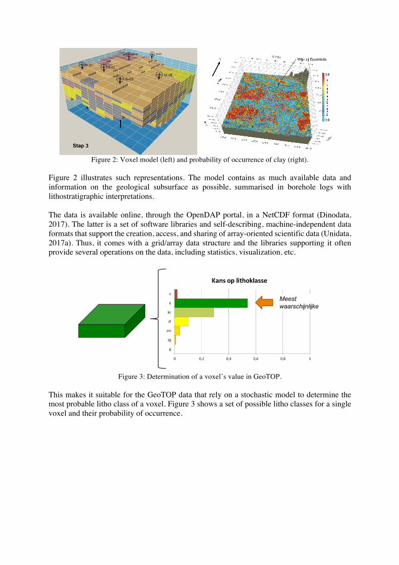
Figure 2: Voxel model (left) and probability of occurrence of clay (right).
Figure 2 illustrates such representations. The model contains as much available data and information on the geological subsurface as possible, summarised in borehole logs with lithostratigraphic interpretations. The data is available online, through the OpenDAP portal, in a NetCDF format (Dinodata, 2017). The latter is a set of software libraries and self-describing, machine-independent data formats that support the creation, access, and sharing of array-oriented scientific data (Unidata, 2017a). Thus, it comes with a grid/array data structure and the libraries supporting it often provide several operations on the data, including statistics, visualization, etc.
Figure 3: Determination of a voxel’s value in GeoTOP.
This makes it suitable for the GeoTOP data that rely on a stochastic model to determine the most probable litho class of a voxel. Figure 3 shows a set of possible litho classes for a single voxel and their probability of occurrence.

3. BIMtoolsandrelatedopenstandard When it comes to building and construction design based on the BIM paradigm, the most prominent open standard is the Industry Foundation Classes (IFC) from the BuildingSMART consortium (BuildingSMART, 2017). IFC is supported by the main software products available on the market (Autodesk Revit, ArchiCAD, Trimble SketchUp, Bentley Microstation, etc.). It comes along with more than 700 classes to describe all the elements related to building infrastructure in general.
Figure 4: IFC model of Rabarberstraat144, Den Haag.
Figure 4 illustrates an IFC model of a building situated in Den Haag (South Holland). Very detailed models can be described by such standard. One can imagine that to create the foundation of such building (or bigger buildings and constructions), it is necessary to dig the ground at a suitable depth, therefore it is necessary to consider the underground configuration of the construction site. However, most of designing tools previously cited focus on the construction itself and their interfaces do not allow to easily deal with geospatial data in order to consider the surrounding environment. As a consequence, the construction’s environment is simply ignored during the designing phase, leading to the increase of accident risks related to the subsurface for example (e.g. ground not suitable for construction, etc.).

4. OurSolutionIn order to make open subsurface data such as GeoTOP readily available in designing tools, we opt for the development of an interface able to translate the GeoTOP data into IFC data in order to make it understandable for the BIM software products. Figure 5 illustrates the workflow of our approach. As mentioned above, further development of the open standard solution into a commercial solution is possible to improve the usability in current design and construction practice. However, for this project the aim is to develop an open standard solution that aligns to the data standard prevailing in the design and construction domain, i.e. IFC, so that it can be expected that any target software can use the data.
Figure 5: Workflow of our solution.
As previously explained, subsurface information is not the focus of IFC, thus there is no class directly suitable for the representation of such data. It is however possible to bypass such limitation by relying on a class that is meant to represent spaces related to the construction and known as the IfcSpace class. At first sight, the definition of the latter seems to exclude exterior: “A space represents an area or volume bounded actually or theoretically. Spaces are areas or volumes that provide for certain functions within a building.” But it is further mentioned that “A space is (if specified) associated to a building storey (or in case of exterior spaces to a site).” (IfcSpace, 2017). Thus, thanks to the possibilities to link IfcSpace entities to a construction site (the exterior), they can be used to model the GeoTOP data.
Identifytheareaoftheconstruction
ExtractcorrespondingGeoTOPdata
Processcorresponding
voxelinformationandattributes
GeneratesIfcSpace
entitieswiththevoxelattributes
ExportanIFCfileofthevoxels

Figure 6: IFC representation compatible with the voxel model of GeoTOP. (source: IfcSite, 2017).
IfcSpace can, indeed, be adapted to our purpose, because it can easily represent a voxel structure as illustrated in Figure 6. The geometric representation is appropriate for the aim we have but the semantic attributed affiliated to IfcSpace entities is a limitation. There is no match between the attributes of a voxel in the GeoTOP data and those of IfcSpace entities. Therefore, here we will have to adapt one attribute of IFC to our purpose. Finally, the IfcSite provides the possibility to set a georeferenced point to be able to situate the construction on a geographical system. This is a critical feature to all tasks involving the integration of BIM and GIS data. In the following sections, we describe the practical implementation of our solution and the issues that arise during the process.

5. ImplementationandResultsWe entirely relied on open source tools to build our solution, implemented in C++. For parsing NetCDF data, the NetCDF C++ API (Unidata, 2017b) has been used. It provides convenient classes to read fully or partially, locally or from a server, grid data stored in NetCDF files. To deal with IFC reading and writing, we relied on the IfcOpenShell library (IfcOpenShell, 2017) that is a robust support for software dealing with IFC. Finally, an optional and simple viewer is provided, to visualize the extracted voxels, and it relies on the libQGLViewer library (libQGLViewer, 2017). 5.1InputdataThe whole GeoTOP voxel model, at its current version (v1.3) can be downloaded as one single file through the OpenDAP server (Dinodata, 2017). The file is 30Gb in size, and may not be very handy to work with, as not the data of the entire Netherlands will be useful to a single construction project. It is however possible to query specific part of the data, by extracting data on specific location.
Figure 7: Map viewer of the DINOloket platform.
As illustrated in Figure 7, it is possible to visualise on a map the area covered by the GeoTOP data, via the DINOloket platform. On the bottom right of the figure, it can be seen the RD-Coordinates of the point where the mouse is located. As the resolution of a voxel is 100 x 100 x 0.5 m, and the depth covered is 50m below the NAP and 106.5m above, the 3D grid model covering the whole Netherlands (see Figure 1) is composed by:
• x: Array of 32 bit Integers x = [0, 2645] • y: Array of 32 bit Integers y = [0, 2615] • z: Array of 32 bit Reals z = [0, 312]
The coordinate of a voxel reference corner will then correspond to an (x,y,z) value. Furthermore, every (x,y,z) value also describes a litho class value of type strat, lithok, kans_1, …, kans_9, onz_lk and onz_ls. The values of those latter classes may not always be relevant, thus a “FillValue” can be attributed to them, symbolising that there is no value for the class (e.g. for voxels above the ground).
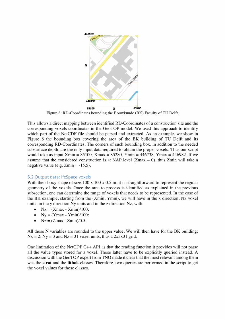
Figure 8: RD-Coordinates bounding the Bouwkunde (BK) Faculty of TU Delft.
This allows a direct mapping between identified RD-Coordinates of a construction site and the corresponding voxels coordinates in the GeoTOP model. We used this approach to identify which part of the NetCDF file should be parsed and extracted. As an example, we show in Figure 8 the bounding box covering the area of the BK building of TU Delft and its corresponding RD-Coordinates. The corners of such bounding box, in addition to the needed subsurface depth, are the only input data required to obtain the proper voxels. Thus our script would take as input Xmin = 85100, Xmax = 85280, Ymin = 446738, Ymax = 446982. If we assume that the considered construction is at NAP level (Zmax = 0), thus Zmin will take a negative value (e.g. Zmin = -15.5). 5.2Outputdata:IfcSpacevoxelsWith their boxy shape of size 100 x 100 x 0.5 m, it is straightforward to represent the regular geometry of the voxels. Once the area to process is identified as explained in the previous subsection, one can determine the range of voxels that needs to be represented. In the case of the BK example, starting from the (Xmin, Ymin), we will have in the x direction, Nx voxel units, in the y direction Ny units and in the z direction Nz, with:
• Nx = (Xmax - Xmin)/100; • Ny = (Ymax - Ymin)/100; • Nz = (Zmax - Zmin)/0.5.
All those N variables are rounded to the upper value. We will then have for the BK building: Nx = 2, Ny = 3 and Nz = 31 voxel units, thus a 2x3x31 grid. One limitation of the NetCDF C++ API, is that the reading function it provides will not parse all the value types stored for a voxel. Those latter have to be explicitly queried instead. A discussion with the GeoTOP expert from TNO made it clear that the most relevant among them was the strat and the lithok classes. Therefore, two queries are performed in the script to get the voxel values for those classes.

Figure 9: Produced voxels for the BK building’s GeoTOP subsurface (visualised on BIM
Vision software). The IfcSpace attribute that seems the most adequate to host the GeoTOP class values appears to be the Description attribute, that comes along with any IfcSpace entity. Based on that, we decided to encode the strat and litho voxel values in the Description of their corresponding IfcSpace. Figure 9 provides an illustration of the output IFC file obtained from the BK building test. On the right side of the image, the attributes from GeoTOP can be seen that was transferred to the voxels.
6. IssuesAlthough the implementation of the proposed solution could be achieved properly, several issues appeared and tend to make the integration between BIM and GIS data painful. Those issues can be summarised into the georeferencing problem of the data from BIM or localising the geo-data inside BIM platforms. Indeed, when it is about merging GIS data such as GeoTOP and BIM data such as IFC, it becomes hard to find a common coordinate system on which both models can be handled. 6.1ModelalignmentissuesGIS data rely on geographic reference systems allowing the precise localisation of its data on a map. The GeoTOP data for example, by relying on RD-Coordinates, allows to situate the voxels it provides properly. On the other hand, BIM data often use local coordinate systems. This is because the latter usually focus on the design aspect of the architectural components at the scale of a single building and such components are usually designed one by one. In this project, since our goal is to mainly provide the possibilities for BIM software products to integrate subsurface data in their interface, we have to consider the alignment of the two types of data under the local coordinate systems of the interface. Our choice to use as much as possible open source tools did not allow us to deeply investigate possible approaches to adopt on the commercial software side, for the purpose. Indeed, once we extract the IFC equivalent to the GeoTOP voxel model, the latter can be imported in the mentioned commercial software (we tested the Revit software). But the process that can be used to align the imported IFC and the BIM model going along with it will depend on the capacity of the software that is used.
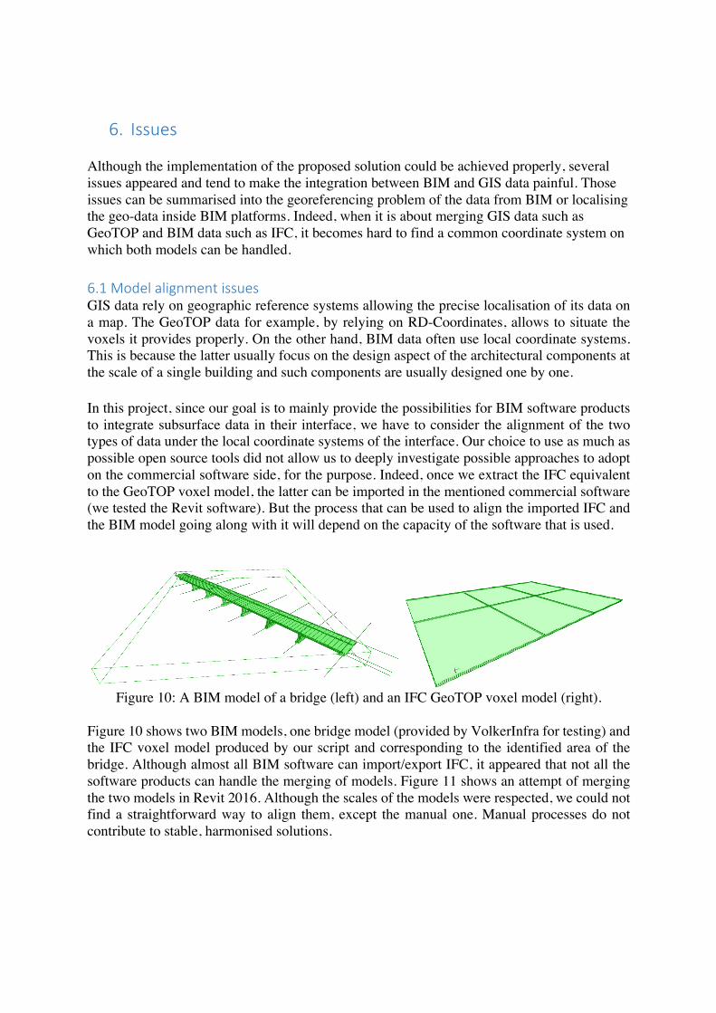
Figure 10: A BIM model of a bridge (left) and an IFC GeoTOP voxel model (right).
Figure 10 shows two BIM models, one bridge model (provided by VolkerInfra for testing) and the IFC voxel model produced by our script and corresponding to the identified area of the bridge. Although almost all BIM software can import/export IFC, it appeared that not all the software products can handle the merging of models. Figure 11 shows an attempt of merging the two models in Revit 2016. Although the scales of the models were respected, we could not find a straightforward way to align them, except the manual one. Manual processes do not contribute to stable, harmonised solutions.

Figure 11: Attempt to align the two models of Figure 10, using Revit 2016.
Therefore, routines allowing to simplify the merging and alignment of the models should be investigated in the future phase of the project. 6.2GeoreferencingThe only moment where we really face the need of having georeferenced information is at the step where we provide input to our script. We then require the RD-Coordinates of the area of interest in order to extract the proper voxel information from the NetCDF data. The georeferencing is mostly an issue when BIM models or part of them need to be used in GIS systems. The local coordinate system on which BIM tools rely on becomes then unusable to geographically locate the BIM model. Therefore, BIM software products tend to consider more and more such options. In order to consider georeferencing parameters in the exchange process of IFC files, the IFC standard proposed the possibility to store geographic coordinates attached to the IfcSite class. The IfcSite entity is intended to describe the area where construction works are undertaken. Therefore, its geographic location is important and may stand as the link between the local coordinates of a building or construction and a global coordinate system. In that sense, the IfcSite class comes along with RefLatitude, RefLongitude and RefElevation attributes (IfcSite, 2017). As their names suggest, the two former ones correspond to the latitude and longitude coordinates with respect to the world geodetic system WGS84, and the last corresponds to the datum elevation relative to sea level. There are also attributes dedicated to land title number (designation of the site within a regional system) and postal address of the site (LandTitleNumber and SiteAddress). The local engineering coordinate system is established by the IfcGeometricRepresentationContext entity, which contains a TrueNorth attribute that relates the axes of the coordinate system to the geodetic North. Thus, by combining the georeferencing attributes of the IfcSite (corresponding to the latitude, longitude and elevation) and the orientation of true North in the coordinate system of the model,

it is possible to properly locate a model on a geographic coordinate system. However, it appears that those attributes are often not filled in correctly by practitioners.
Figure 12: Wrong georeferencing information in the building model of Figure 4. Given
position (left). Distance between given and real position (right). For example, Figure 12 illustrates the provided position of the reference point (latitude and longitude) given in the attributes of the Rabarberstraat 144 model (see Figure 4), compared to its real one in (right image). We can see that the provided point corresponds to the centre of a roundabout in the city of The Hague (left image) and therefore appears to be chosen manually and on purpose. This can be explained on one hand by the fact that the georeferencing issue is not the first concern of BIM practitioners in the design phase, and on the other hand, when they may need it, it can be just for indicative purposes. Furthermore, there are no rules or specifications to force BIM practitioners to fill in the proper information at the design phase or at the generation of IFC files. Consequently, such type of information is not always present in IFC. In the specification of the latter, the single geographic reference point for the construction site may specify the exact position of the origin of the local placement, or an approximation of it. That latter statement makes it then possible to provide inaccurate locations.

7. Conclusionsandrecommendations The aim of this project was to investigate and develop an open solution to improve accessibility of geological subsurface data in the Netherlands in BIM software. We developed an interface from which relevant data from the GeoTOP database stored in NetCDF can be extracted and be made available in the open BIM standard IFC, based on an area of interest. The obtained insights can serve as input for further development of the BRO. From our experiments, we can conclude that technically it is possible to provide BIM-practitioners with subsurface data. However, since using geo-data in BIM software and vice versa is far from common, it requires further attention to make the use of subsurface data in BIM software straightforward. For this we formulated the following recommendations. - Investigation of practices of the BIM practitioners is needed when it comes to deal with
subsurface issues. To obtain first understanding of how they use (or would like to use) subsurface data, we set up a small questionnaire, which was distributed as part of the BIM-loket newsletter1. The responses (see Appendix 1) indeed show that BIM practitioners are interested in subsurface data, but currently meet difficulties using the data. Although it must be said that it was very hard to get them involved. In this project, we have also tried to organise a BIM vendor’s session, but without success (i.e. there was no or little interest). The involvement of BIM practitioners requires specific attention in the follow up. To further support the use of subsurface data in the BIM domain, more understanding is needed on how BIM practitioners design their data and how they take into account data about the environment, and how they are best served with subsurface data. This also entails distinguishing between different types of BIM practitioners and identifying which BIM practitioner can be served with the subsurface data. It might be that the designer of an individual building (which takes place after the planning phase) focuses entirely on the building while in an initial phase the process of plan preparation can be improved by the use of subsurface data (and other data about the environment) to fit the plan in the environment.
- A clear condition to integrate subsurface data with BIM models is that BIM models are correctly positioned in the real world, while this has currently little attention in the BIM domain. Therefore, another important recommendation is to make the BIM world aware of the importance of positioning their models in the real world. A discussion should be started between BIM and GIS practitioners for better handling of georeferencing/alignment practices and the establishment of guidelines to support this. Also here it makes sense to distinguish between different types of BIM practitioners and to develop a solution for those processes where the integration between BIM and subsurface contribute to better decision making,
- Development of more similar tools, able to handle other types of subsurface data with more/different coverage. This will allow to democratise such type of data in BIM environments.
- Investigation of possible approaches to allow the automatic integration/alignments of the models in either BIM or GIS systems.
1Thequestionnairecanbefoundherehttps://docs.google.com/forms/d/1EZkw8PtVFcd5VJyoZouv9piz0LMlkRJqQIZbitfNE2E/edit#responses

- Investigating the issues of integrating subsurface data, represented in voxels of size 100mx100mx0.5m (of which the values are obtained from interpolation), with objects represented in BIM that have a much higher accuracy. BIM sites would usually fall within a complete voxel or a few voxels only (where it concerns X,Y). What is the value of conclusions drawn from this data integration which may have severe impact on a risk analysis? This requires close involvement of experts of the geological data.
The main aim of this work was to support the development of the BRO by taking away the incompatibilities between the formats in which subsurface data are encoded and delivered by TNO on the one hand, and the tools that are used by designers of infrastructure projects on the other hand. Besides solving the technical incompatibilities, it is important to obtain deeper understanding in how the BIM field can make appropriate use of the subsurface data including understanding and dealing with the inherent uncertainties of the data. This knowledge can be input for the BRO (i.e. shaping/modelling the BRO in such a way, that optimal use is assured). Further involvement of BIM professionals is required as well as with the BIM software vendors both to make them aware and to motivate them to embed the BRO solutions within their software. Specific attention is therefore required to make them part of the BRO process and to explore the above-mentioned challenges (and potentials!) with them.

References
1. DINOloket, 2017a. Data and Information on the Dutch Subsurface. https://www.dinoloket.nl/en/about-us
2. DINOloket, 2017b. GeoTOP, more detail for the upper 50 meters. https://www.dinoloket.nl/en/geotop-more-detail-upper-50-meters
3. Unidata, 2017a. NetCDF, https://www.unidata.ucar.edu/software/netcdf/ 4. Uindata, 2017b. NetCDF C++, https://www.unidata.ucar.edu/software/netcdf/netcdf-
4/newdocs/netcdf-cxx.html 5. Dinodata, 2017. OPeNDAP Server Dataset Access Form,
http://www.dinodata.nl/opendap/GeoTOP/geotop.nc.html 6. BuildingSMART, 2017. Industry Foundation Classes (IFC),
http://www.buildingsmart-tech.org/specifications/ifc-overview 7. IfcSite, 2017. IFC4 schema, http://www.buildingsmart-
tech.org/ifc/IFC4/final/html/schema/ifcproductextension/lexical/ifcsite.htm 8. IfcSpace, 2017. IFC4 schema, http://www.buildingsmart-
tech.org/ifc/IFC4/final/html/schema/ifcproductextension/lexical/ifcspace.htm 9. IfcOpenShell, 2017, http://ifcopenshell.org. 10. libQGLViewer, 2017. http://libqglviewer.com

Appendix1 Response of small questionnaire investigating current practice of using subsurface data by BIM practitioners
Bent u geïnteresseerd in gegevens over de geologische ondergrond? 100% ja Bent u bekend met gegevens over de ondergrond? 25% nee; 75% ja Heeft u de TNO gegevens over de geologische ondergrond wel eens gebruikt of proberen te gebruiken? 25% ja (over diepe boringen en seismiek met Petrel software); 50% nee; 25% blank Welke open standaard is voor u het meest geschikt om gegevens over de geologische ondergrond te ontsluiten? IFC, GML Heeft u behoefte aan een 'de facto' (commerciële) standaard voor gegevens over de geologische ondergrond? 75% ja, namelijk: Revit, DWG, DGN Wat is uw ervaring met het georefereren van BIM modellen (goed?slecht? hoe?) Niet veel of geen geode ervaring