Embed Size (px)
Citation preview

AD-AI05 667 DELAWARE UNIV NEWARK CENTER FOR CATALYTIC SCIENCE AN-ETC F, 8/7DEVELOPMENT OF SUPERIOR DENITROGENATION AND ISOMERIZATION CATAL-ETC(U)AUG 81 J R KATZER, A B STILES, H KWART N00019-80-K-0507
UNCLASSIFIED NLEhEEEEEEEEEIIEIIIIEIIIIIF

Y2
DEVELOPMENT OF SUPERIOR DENITROGENATION
AND ISOMERIZATION 9ATALYSTS FOR PROCESSING
CRUDE OIL DERIVED FROM SHALE. PART I
FinalFinal ,r on Pr ' N 1OZ9-80-K-0507
for Noal Air Systems Comzand.
Interim Report on Total DTICProject. This Report Covers ELECTEStart-up Period of Assembling OCT 1 6 1981
Equipment and Personnel
,i JS 4u , '-x.'- B
by
Center for Catalytic Science and TechnologyDepartment of Chemical Engineering
University of Delaware / JNewark, Delaware 19711
Principal Investigators:
( / James R.'Katzer Harold Kwart
Alvin B. Stiles
C-,
APPROVED FOR PUBLIC RELEASE.DISTRIBUTION UNLIMII1
I--,

1
DEVELOPMENT OF SUPERIOR DENITROGENATION
AND ISOMERIZATION CATALYSTS FOR PROCESSING
CRUDE OIL DERIVED FROM SHALE. PART I
INTRODUCTION
This study was undertaken and continues primarily
because of the following well-known facts:
1. The domestic supply of easily processed light
petroleum crude oils is insufficient to meet the needs of
the United States.
2. Foreign sources of fuel are undependable for
both political and logistic reasons.
3. Shale oil is abundant in the United States and
offers the best opportunity of augmenting the inadequate
domestic petroleum supply.
4. Shale oil is unusually high in nitrogen and sulfur
content and these catalyst poisons and atmospheric pollutants
cannot be removed by existing processes, which are successfully
applied commercially to light petroleum crude.
5. New catalysts and processes must be developed to
successfully process crude shale oil.
It is the thrust of the work performed in Part I of
this project to initiate the program. This involved the
review of literature as shown in the appended literature and
APPROVED FOR PUBLIC RELEAMDISTRIBUTION UNUMIID

2
patent references, meetings with people who are knowledge-
able in both the analytical and process phases of hydrode-
nitrogenation, obtaining as complete information as possible
about the products from various shale oil recovery processes
and finally dove-tailing this work with denitrogenation
mechanism studies being concluded concomitantly on model
compounds by Center personnel on a DOE project.
It should be emphasized at this time that the first
six months' effort supported on Part I was basically the
initiation of the project but that this work paved the way for
the achievements under Part II currently under way. Part II
results will be reported in about three months, but it can
presently be said that superior catalysts have been devised and
the prospects are bright for still further major improvements.
As a consequence of the fact that Part I involved
primarily the initiation of the study, this "final report"
will be brief but the "final report" due for Part II in a few
months is expected to contain a substantial amount of
important new information.
Background to the Development of a SuperiorHydrodenitrogenation Catalyst
Much work related to the objective of the project has
been performed here at the Center under other projects and
naturally becomes a valuable background for this project. In

3
the interest of conciseness, this information is reviewed
and placed in an appendix hereto but becomes an important
part of the reference material for the current project.
It is thus made available for those interested therein.
ACCOMPLISHMENTS UNDER PART I OF THIS PROJECT
The accomplishments in Part I have been primarily the
setting of the stage for the studies to follow. These relate
to the following in order of time and money involved.
Analytical
First was the derivation of rapid and accurate methods
and facilities for the analysis of crude and fractionated shale
oil. Heretofore analyses have been made either by the gas
chromatographic technique or by the Kjeldahl wet method. The
former is not applicable to the complex, partially non-volatile
nitrogen compounds whereas the latter, while accurate, is time
consuming and requires space and special facilities.
Although our first approach to people working in
organic nitrogen analysis was discouraging, a source in duPont
informed us of a newly developed total combustion technique
which they had used for agrichemicals analysis; they had been
able to adapt it to their use after some applications develop-
ment. The vendor (Antek) was contacted and some modifications
i A,,' I bi lty Co:u
I A~':1 I and/or
D t 1,
4
were agreed to and the equipment was purchased on a condi-
tional basis. The principle involved was total combustion
of the sample to form NOx and the subsequent oxidation of the
NOx to N02 with ozone. The NO2 was passed through a flame
and a detector measured luminescence induced by the NO2 .
It was necessary to make adjustments in the ozonator
but when the proper oxygen flow had been derived and the
ozonator adjusted, analyses have been rapid and have been
reproducible; analysis by other means in other laboratories
have corroborated the results.
Analyses for sulfur are also made with the same total
combustion facilities. The sulfur is oxidized to S02 which
is quanitized in a suitably calibrated chromatograph.
The analyses are now possible on a routine basis and
make it possible to have a three-day cycle for making the test
and analyzing the products. Catalyst preparation is done
separately by another person (graduate student) assigned to
the effort.
Obtaining Samples of Crude Shale Oils
Samples of crude shale oil were obtained from Suntech
who had the three types: Paraho, Occidental, Technetics
with the complete analyses as tabulated below:

5
Avg. %Ramsbottom Mol.No. Wt. C H2 S N2
Paraho 2.5 326 84.3 11.29 0.66 2.18
Technetics --- 84.5 11.69 0.48 1.66
Occidental 85.95 12.26 0.91 1.16
ppm
Cont 02, % As Fe
Paraho 1.16 28 70
Technetics 1.75 20 60
Occidental 1.0 -- --
These are currently being investigated for detoxifi-
cation but data will be reported at the conclusion of Part II.
The samples are being maintained in a sealed bottle and
opening and exposure to oxygen is minimized.
Hydrodenitrogenation, Hydrodesulfurization andIsomerization Facilities
These stirred autoclaves were made available from
related work on a related project sponsored by the Department
of Energy. These facilities are being used for both projects
and have served very well. A word of caution should be given
however, in that as these facilities age, problems relating
to tight seals and closures increase. As a consequence, the
maintenance costs are increasing but not to the extent
necessary to justify new facilities.

6
The facilities consist of two high-pressure agitated
autoclaves built by Autoclave Engineers but designed or
specified by Center personnel. The facilities are capable
of operating at pressures to 2500 psi and at temperatures to
450*C. It should be noted parenthetically that the majority
of our runs are being made at 500-1000 psi and 350 0C but some
later runs made under more severe conditions and with the more
refractory shale oils indicate that these more severe condi-
tions may be required or desired even with the more effective
catalysts. Although our objective is to derive catalysts
which are responsive under mild conditions, the overall
objective will be to attain optimum efficiency cost-wise.
A test is made by charging the shale oil dissolved in
hexadecane to the autoclave with the catalyst suspended as a
slurry in this solution. Temperature and pressure are
increased to the selected operating conditions and are main-
tained for the duration of the test. Samples are withdrawn
periodically for analyses. The draw-off line is flushed so
that the sample taken is representative of the slurry in the
autoclave. When appropriate, samples can also be taken from
the vapor space to analyze for volatiles such as ammonia,
hydrogen sulfide, arsine or other components suspected as
being present.
The equipment is thoroughly cleaned between runs to
prevent contamination and possible poisoning of subsequent

7
runs. It is noteworthy that there appears to be some severe
poison in the crude shale oils which have a very adverse
effect on the hydrodenitrogenation reaction. This component
"X" is unknown but could be one of many things such as arsenic,
alkali, blinding solid or tar. This problem is to be elucidated
in Parts II and III of this project.
UTILIZING BACKGROUND INFORMATION DERIVED FROM COMPANIONPROJECT ANALYZING DENITROGENATION ROUTES OF SPECIFICMODEL COMPOUNDS
Background to a Program for Development of aSuperior HDN Catalyst
The Structures as the Active Site and the Mechanisms
of Action of Sulfided Molybdic Catalysts for HDN
Evidence of both physical (x-ray photoelectron
spectroscopy) and chemical nature has accumulated during the
past three years showing that there are two fundamental
molybdenum-containing structures present in a sulfided
molybdic oxide catalyst and these structures are readily
interconverted in high pressures of H2S. This equilibrium
may be expressed by equation (1), where the symbol 0 is
used to designate an anionic vacancy.
s. 0 + H2S HSN ,SH_e -H2S 0 -o'0O 0"1
1 2
.4.

8
Detailed study of the reaction network for HDN of
quinoline has yielded a number of valuable conclusions. One
of the most significant among these holds that hydrogenation
and hydrogenolysis steps in the network case often occur in
quick succession on what appears to be a single active site.
Observations of this nature have led to the conclusion that
the active site is capable of playing both roles--hydrogenation
and hydrogenolysis agent--subject to the activity of other
reagents in the medium such as H2 and H2 S. In this way we
have come to recognize that the structure 2 functions in a
hydrogenation role, a conclusion for which there is much
support in the literature on molybdic centered catalysts such
as the enzyme nitrogenase. The structure 1 has long been
implicated as one which is involved with hydrogenolysis activity
although there has been some dispute as to how this is effected.
One of the most significant conclusions we have reached
in our studies of the quinoline network is that the HDN
reaction of an heteroaromatic or aromatic amine requires a
preliminary hydrogenation of the aromatic ring. It is only
the hydroaromatic, alicyclic or aliphatic amines which can
suffer C-N bond breaking in the subsequent hydrogenolysis step.
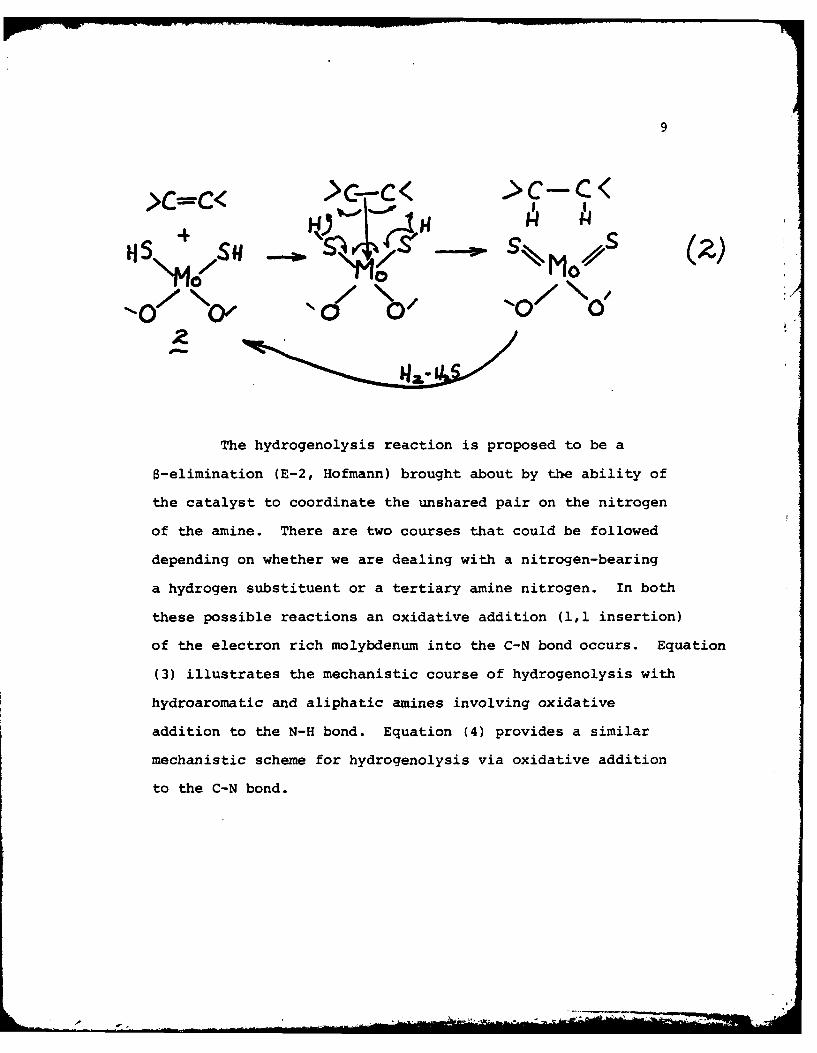
The hydrogenation step appears to occur on the active site via
the mechanistic steps depicted in equation (2).
9
> =c< > _, G- < hC
0 /4
iS,., s _ ,1_4 o/ (z)SH/ \o - " -o-o'
00 0'
The hydrogenolysis reaction is proposed to be a
8-elimination (E-2, Hofmann) brought about by the ability of
the catalyst to coordinate the unshared pair on the nitrogen
of the amine. There are two courses that could be followed
depending on whether we are dealing with a nitrogen-bearing
a hydrogen substituent or a tertiary amine nitrogen. In both
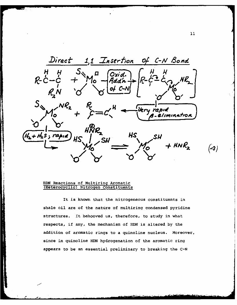
these possible reactions an oxidative addition (1,1 insertion)
of the electron rich molybdenum into the C-N bond occurs. Equation
(3) illustrates the mechanistic course of hydrogenolysis with
hydroaromatic and aliphatic amines involving oxidative
addition to the N-H bond. Equation (4) provides a similar
mechanistic scheme for hydrogenolysis via oxidative addition
to the C-N bond.
-.

10
+ 14o ~j4dd4$0 1 &&c
c 'OS
AS14S I141q10 10 -t-HN-(3
00
0I
.Direce -ZnI.2sertlonz O C-iV B~ond
,, S6 3 ol-xid"
J~O+ _____0 - _ ___
S' eI Jvci: //e At,- ,. .IN. -
RN_ --0 \td
-1-0
HDN Reactions of Multiring Aromatic(Heero~clc)Nitrogen Constituents
It is known that the nitrogeneous constituents in
shale oil are of the nature of multiring condensed pyridine
structures. It behooved us, therefore, to study in what
respects, if any, the mechanism of HDN is altered by the
addition of aromatic rings to a quinoline nucleus. Moreover,
since in quinoline HDN hydrogenation of the aromatic ring
appears to be an essential preliminary to breaking the C-N
Ne
'O )
12
bond in a subsequent hydrogenolysis reaction, we must ask how
the presence of additional aromatic rings affects the rate of
overall N-removal; the stoichiometry of hydrogen uptake must
also be considered.
Tables I and II provide a listing of the results we
have obtained in a short study of the problems presented
above, preliminary to undertaking to apply the results to our
objective of designing the most efficient HDN process for
refining shale oil.
For purposes of immediate application to shale oil,
the most important conclusions derived from this preliminary
work are the following:
1) As with quinoline, total nitrogen removal in
multiring condensed heterocycled amines involves hydrogenation
of the aromatic rings followed by (an often slower) process
of C-N bond scission.
2) With multiring substrates of this nature the ring
hydrogenation occurs more rapidly than the C-N bond scission
reactions leading to the accumulation o considerable concen-
trations of hydrogenated nitrogen-containing species in the
reaction mixture.
3) The overall rates of N-removal do not vary
significantly because the rates of C-N bond scission in these
hydrogenated species are quite similar.

13
4) The rates of these reactions would appear to
be somewhat affected by steric hindrance to adsorption
caused by the puckered cyclohexane rings and the similarity
of rates must be due to the similarity of the steric effects.
The Significance of our Preliminary Study Results inDetermining our Approach to the Catalyst DevelopmentObjectives
As summarized above, we have perceived that, aside
from an increased stoichiometric requirement for hydrogen
(uptake), the size of the multiring heterocyclic components
of shale oil do not alter the network character- and mechanism
of HDN which has previously been elucidated for quinoline.
Thusthe reportedly high resistance of shale oils to the HDN
process with sulfidedpromotedmolybdic oxide catalysts is
not necessarily due to the inherent non-reactivity of its
heterocyclic nitrogen constituents. In the light of results
obtained in our preliminary study, the rate-determining steps
in the HDN of such species must be related to difficulties in
hydrogenation and the requirement for taking up a large amount
of hydrogen prior to effecting C-N bond breaking. Consequently,
the hydrogenation function of the catalyst becomes the most
critical one to consider in catalyst design and development.
In this connection also there appears to be still
another factor to consider. Since the active site for sulfided
-.- A

14
molybdic catalysts (in their hydrogenation function) is one
in which the central molybdenum (see structure 2, equation (1))
must coordinate an electron donor species, (in this case the
pi electrons of a C=C bond), a hydrogenation poison would be
one which could preferentially and tenaciously displace the
normal hydrogenation substrate. Shale oil, like all other
naturally occurring mixtures, undoubtedly is rich in such
potential poisons of the hydrogenation functionof the common
catalysts used and this could be the reason why shale oil
appears to be so refractory to the action of common HDN
reaction conditions.
In view of these considerations, we have undertaken the
following approaches:
A) If the poisoning components of shale oil should
prove to be of organic nature, we would try to subject the
shale oil to a preliminary hydrogenation experience. We would
attempt to use hydrogenation catalysts that are known to be
quite resistant to such poisoning even though they did not
possess hydrogenolysis properties. Some candidate hydrogenation
catalysts presently being tried are platinum sulfide on
charcoal, a well-known catalyst for reducing aromatic amines
under relatively mild conditions and known to be resistant to
poisoning by sulfur compounds to which most other hydrogenation
catalysts (under mild conditions) such as Raney nickel are
highly susceptible.
*
-
15
B) If the poisoning components of shale oil should
prove to be of largely inorganic nature, such as (for example)
arsenic and antimony complexes, we must try to devise a
catalyst support or carrier which would be most effective in
sequestering the poisonous components and prevent their
becoming bound to the active site for hydrogenation. As
discussed in the other sections of this report, our efforts
in this direction are presently in progress.
CONCLUSION
There are no conclusions to be drawn at this time,
but it is expected that when preparing the final report for
Part II there will be important conclusions and inferences
to present.
_/A

TABLE I
STRUCTURE, NOMENCLATURE AND BASICITY OF SELECTEDNITROGEN-CONTAINING COMPOUNDS
pKa(H 2 0) *Compound Formula Structure 298 K
Pyridine C5H5N 5.23
quinoline C9H7N 4.94
acridine C1 3H9 N 5.60
benz [clacridine C17HllN 4.70
benz [a] acridine C1 7HIIN 3.45
dibenz[c,h]acridine C2 1H1 3N <3.45a
fEstimated from inductive and steric factors influencing (proton)basicity.

TABLE II
REACTIVITY OF SELECTED NITROGEN-CONTAINING COMPOUNDSTOWARD HDN CATALYZED BY SULFIDED Ni-Mo/y-AI2 3
Pseudo First-Time Required Conversion Order Ratefor 100% of Total Constant forConversion Organic Total Nitrogenof Reactant, Nitrogen Removal, cmi/g •
Reactant min in 300 min_% of Catalyst-hr
pyridine --- %15000
quinoline 145 98 3375
acridine 30 91 2160
benz[c]acridine 45 69 2058
benz[a]acridine 45 67 1451
dibenz[c,hjacridine 5 100 5063
Reaction conditions given in Table I, pseudo first-order rateconstant for total nitrogen removal defined by
Mo dC -KC.
McJ

18
Literature References
1. AFAPL-TR-75-10, USAF Tech. Rpt. "Evaluation of Methods toProduce Aviation Turbine Fuels from Synthetic Crude Oils,Phase 2," Exxon R&E Co., Linden, N.J., May 1976.
2. Aiyar, V. N., 0. H. Houwen, and F. W. Bachelor. Distributionof Nitrogen in Fractions of Athabasca Bitumen. Fuel, v. 59,April 1980, pp. 276-278.
3. Applied Systems Corp., Vienna, Va. "Compilation of OilShale Test Results," ONR Contract N00014-76-C-0427,April 1976.
4. H. Bartick, et al. "The Production and Refining of CrudeShale Oil into Military Fuels," Applied Systems Corp.,Vienna, Va., ONR Contract N00014-75-C-0055, August 1975.
5. D. W. Brinkman, M. L. Whisman and J. N. Bowden, BartlesvilleEnergy Technology Center. Report of Investigation No. 78/23,March 1979.
6. Buell, B. E. Nonaqueous Differential Titration Applied toa Classification of Basic and Very Weak Basic NitrogenCompounds in Petroleum. Anal. Chem., V. 39, No. 7.,June 1967, pp. 756-761.
7. Bunger, J. W., K. P. Thomas, and S. M. Dorrence. CompoundTypes and Properties of Utah and Athabasca Tar SandBitumens. Fuel, v. 58, March 1979, pp. 183-195.
8. Business Week. Money for Synfuels May Soon Start to Flow.June 1, 1981, pp. 32 and 33.
9. Business Week. America's Restructured Economy-Energy.June 1, 1981, pp. 68-74.
10. S. E. Buttrill, Jr. Analysis of Jet Fuels by MassSpectrometry, in Naval Research Laboratory Workshop on BasicResearch Needs for Synthetic Hydrocarbon Jet Aircraft Fuels,Naval Air Systems command, June 15-16, 1978, and referencestherein.
11. D. R. Clutter, L. Petrakis, R. L. Stenger and R. K. Jensen.Anal. Chem., 44, 13.95 (1972).
12. Cumins, J. J., R. E. Poulson, and W. E. Robinson. NitrogenCompounds Types in Green River Oil Shale and Its KerogenDegradation Products. Preprints, ACS Div. Fuel Chem., v. 20,No. 2, 1975, pp. 154-161.

19
13. H. F. Drushel. Anal. Chem., 49, 932 (1977).
14. Eccles, R. M. and G. R. DeVaux. Current Status of H-CoalCommercialization, Chem. Engr. Progress, May 1981, pp. 80-85.
15. Energy Insider, U.S. Dept. of Energy. Two ExperimentalSynfuel Plants Complete Extended Continuous Runs. April 27,1981, pp. 1 and 7.
16. Epperly, W. R., D. T. Wade and K. W. Plumlee. Donor SolventLiquefaction. Chem. Engr. Progress, May 1981, pp. 73-79.
17. Flinn, R. A., 0. A. Larson, and H. Beuther. How Easy isHydrodenitrogenation? Hydrocarbon Processing and Petrol.Refiner, v. 42, No. 9, September 1963, p. 129 on.
18. Ford, C. D., S. A. Holmes, L. F. Thompson, and D. R. Latham.Separation of Nitrogen Compound Types from HydrotreatedShale Oil Products on Basic and Neutral Alumina. To bepublished.
19. (a) J. W. Frankenfeld and W. F. Taylor, Final Report underNaval Air Systems Command Contract No. N-0019-76-0675,Feb. 1979, and references therein; (b) B. Witkop, J. Amer.Chem. Soc., 72, 1428 (1950); (c) B. Witkop and J. B. Patrick,J. Amer. Chem. Soc., 73, 713 (1951); (d) I. Saito,T. Matsuura, M. Nakagawa and T. Hino, Accts. Chem. Res., 10,346 (1977); (e) R. J. S. Beer, L. McGrath, and A. Robertson,J. Chem. Soc., 3283 (1950).
20. Freel, D. M. Jackson and B. K. Schmid. The SRC-IIDemonstration Project. Chem. Eng. Progress, May 1981,pp. 86-91.
21. C. M. Frost and R. E. Poulson. Amer. Chem. Soc., Div.Petroleum Preprints, 20, 176 (1975).
22. Frost, C. M., and H. B. Jensen. Hydrodenitrogenation ofCrude Shale Oil. Preprints, ACS Div. Petrol. Chem., v 18,No. 1, 1973, pp. 119-128.
23. Haines, W. E., G. L. Cook, and G. U, Dinneen. Techniquesfor Separating and Identifying Nitrogen Compounds inPetroleum and Shale Oil. Seventh World Petroleum Cong.,Proc., v. 9, 1967, pp. 83-92.
24. (a) R. N. Hazlett, J. M. Hall and M. Matson, Ind.Eng. Chem.,Prod. Res. Dev., 16, 171 (1977); (b) D. M. Brown and A. Fish,Proc. Roy. Soc., A08, 547 (1969); (c) N. M. Emanuel, E. T.Denisov and Z. K.-izus, The Liquid Phase Oxidation ofHydrocarbons, Plenum Press, New York, 1967.

20
25. Koros, R. M., "Scale-Up Considerations for Mixed-PhaseReactors," to be presented at the NATO multiphaseChemical Reactor Conference, 1981.
26. Koros, R. M., S. Bank, J. E. Hoffman, and M. I. Kay,Hydrodenitrogenation of Shale Oil. Preprints, ACS Div.Petrol. Chem., v. 12, No. 4, 1967, B165-B174.
27. McKay, J. R., J. H. Weber, and D. R. Latham, Characteri-zation of Nitrogen Bases in High-Boiling PetroleumDistillates. Anal. Chem., v. 48, No. 6, May 1976,pp. 891-898.
28. Morandi, J. R., and R. E. Poulson. Nitrogen Types inLight Distikltes from Aboveground and In Situ CombustionProduced Shale Oil. Preprints, ACS Div. Fuel Chem., v. 20,No. 2, 1975, pp. 162-174.
29. Poulson, R. E., C. M. Frost, and H. B. Jensen. Character-istics of Synthetic Crude from Crude Shale Oil Producedby In Situ Combustion Retorting. Shale Oil, Tar Sands,and Related Fuel Sources, ed. T. F. Yen, Advances inChemistry Series, 1976, pp. 1-10.
30. Poulson, R. E. Nitrogen and Sulfur in Raw and Refined ShaleOils. Preprints, ACS Div. Fuel Chem., v. 20, No. 2, 1975,pp. 183-197.
31. T. W. Reynolds. National Aeronautics and Space Adminis-tration, Technical Memorandum No. TM-X-3551, June 1977.
32. G. A. St. John, S. Z. Buttrill, Jr., and M. Anbar, Ch. 17,"Field Ionization and Field Desorption Mass SpectrometryApplied to Coal Research," in ACS Sym. Series No. 71,Organic Chemistry of Coal, ed. John Larson, 1978.
33. Shah, Y. T., Gas-Liquid-Solid Reactor Design, McGraw-Hill,New York City, 1979.
34. Silver, H. F., N. H. Wang, H. B. Jensen, and R. E. Poulson.A Comparison of Shale-Oil Denitrification Reactions OverCo-Mo and Ni-W Catalysts. Science and Technology of OilShale, ed. T. F. Yen, Ann Arbor Science Library Congress,Catalog Card No. 75-10415, ISBN 0-250-400 92-8, 1976.
35. J. Solash, R. N. Hazlett, J. M. Hall and C. J. Nowack.Fuel, 57, 521 (1978).
36. Sonneuans, J, F. Goudriaan, and P. Mars. The Hydrogen-olysis of Pyridine on Molybdenum Oxide Containing Catalysts.Paper No. 76 at 5th International Congress on Catalysts,Palm Beach, Fla., 1972.

21
37. Sullivan, R. F., B. E. Stangeland, D. E. Green, C. E. Rudy,and H. A. Frumkin. Refining and Upgrading of Synfuelsfrom Coal and oil Shales by Advanced Catalytic Processes.Interim DOE Report, Category UC-90d, No. FE-2315-25, April1978.
38. Uden, P. C., A. P. Carpenter, Jr., H. M. Hackett, D. E.Henderson, and S. Siggia. Qualitative Analysis of ShaleOil Acids and Bases by Porous Layer Open Tubular GasChromatography and Interfaced Vapor Phase InfraredSpectrophotometry. Anal. Chin., v. 51, No. I 'January1979, pp. 38-43.
39. Vogh, J. W., S. A. Holmes, G. P. Sturm, Jr., P. W.Woodward, and J. E. Dooley. Characterization of Hydro-treated TOSCO Shale Oil. ERDA/BERC RI-77/17, 1977,18 pp.
40. C. C. Ward, P. C. Schwartz and M. L. Whisman, TechnicalReport #11 under Ordinance Project TS5-01-010, BartlesvilleEnergy Technology Center, July 1961.

22
Promoters for Catalyst
Reference No. Patent Inventor(s) Promoter(Con't)
41 3,345,286 (1967) J.M. Kovach and Rare earthS.E. Rogers
42 3,383,305 (1968) Mn as promoter
43 3,383,306 (1968) Vanadium ascatalyst
44 3,422,002 (1969) Pt as promoter
45 3,644,197 (1972) A.E. Kelley and Pt as promoterF.C. Wood
46 3,723,299 (1973) H.W. Seitzer Mn as promoter
47 4,052,296 (1977) A.A. 14ontagra Zinc as promoter
48 4,139,492 (1979) R.J. Poland and FluorobenzoicJ.D. Voorhies acid as promoter
49 4,152,251 (1979) G.A. Michelson Fluorine as promoter
Catalyst Supports
Patent Inventor(s) Support
50 3,367,862 (1968) R.B. Mason Charcoal
51 3,969,273 (1976) S.M. Brown and Al phosphateD.M. Wallace
52 4,065,380 (1977) H.E. Swift and Synthetic micaR.F. Vogel montmorillonite
53 4,128,505 (1978) R.J. McKovsky and TrO -ZrOA.J. Silvestri 2 2
Catalysts
Patent Inventor(s) Novelty
54 3,639,268 (1972) J. Jaffe and Fluorine containingJ.R. Kolvell alumino silicate
55 3,676,332 (1972) M.M. Johnson and Molybdenum arsenicD.C. Tabler as catalyst


![Decarbonisation of Olefin Processes using Biomass … · · 2016-04-1764 processes for hydrodesulfurization (HDS) and hydrodenitrogenation (HDN) in petroleum refineries 65 [27]](https://img.dokumen.tips/doc/110x75/5af3ccd27f8b9a190c8c243f/decarbonisation-of-olefin-processes-using-biomass-processes-for-hydrodesulfurization.jpg)