Embed Size (px)
Citation preview

eGRID Introduction and Status
2nd International Workshop September 17th, 2014
Driving economic growth, innovation, and workforce development for South Carolina

Clemson University Restoration Institute
SCE&G Energy Innovation Center
Duke Energy eGRIDCenter
15 MW HIL Grid Simulator
Wind Turbine Drivetrain Testing Facility
7.5 MW Test Bench 15 MW Test Bench
The SCE&G EnergyInnovation Center

The EGRID Center Team Members J. Curtiss Fox, PhD Randy Collins, PhD, PE Thomas Salem, PhD, PE Mark McKinney, PhD Ramtin Hadidi, PhD Eric Bosnic Benjamin Gislason Mark Milcetich
Director of Operations Project Co-PI Research Scientist Visiting Research Scientist Research Scientist Research Engineer Research Engineer Electrical Technician
Graduate Students: Lindsey Stephens Nikitas Zagoras
MSEE MSEE
Undergraduate Students: Diana Agrest Clemson University Tyler Vasas The Citadel
The SCE&G Energy Innovation Center

Transforming the electrical grid intoan energy efficient network requires: • new technologies that must play a significant role in power system stability. • the ability to replicate a complex dynamic system like the electrical grid for
testing purposes. • extensive testing of hardware and software to meet safety and quality
assurance requirements through ‘fully integrated’ system testing. • parallel model verification and validation of physical hardware to ensure
higher reliability and stability once deployed on the electrical grid.
Advanced Testing Lowers the Risks and Costs of New
Development Demonstration Verification
Technology Introduction into the Market
Deployment Risks Time to Market Total Costs

How the EGRID center fits into the technology development cycle
Design and Development
Independent Certifications
Demonstration Projects
Commercial Deployment
• Simulations • Functional Testing • Controls Algorithms
• Equipment Safety • Basic Functionality
• Complete Systems • Controls Verification
• Operations Training • Technician Training
Prototype Testing
Standards Testing
(UL, IEC, IEEE)
Hardware-in-the-Loop Testing
Academics and Education

eGRID Founding Partners
eGRID Market Applications Large Solar Micro-Grid EV Charging Utility Scale
PV Converters Applications Stations Energy Storage
Traditional Distributed Smart Grid Wind Energy Generation (Diesel, NG. etc.) Technologies Aerospace

SCE&G Energy Innovation Center 23.9 kV Utility Bus
7.5MW Test Stand
15MW Test Stand
Graduate Education Center 500 kW Solar Array (Future)
23.9 kV 20 MVA Test Bus
Experimental Bay #1 Experimental Bay #2 Experimental Bay #3
20 MVA HIL Grid Simulator
Up to three independent grid integration tests can run simultaneously in each of the three experimental bay’s
4.16 kV 5 MVA Test Bus

SCE&G EIC Electrical Single Line
Variable 23.9 kV (50/60 Hz)
Main Facility Electrical Bus (23.9 kV)
20 MVA HIL Grid Simulator

- - -
- - -
- - -
The 20 MVA HIL Grid Simulator Three Independent Test Bays
Overall Electrical Capabilities Main Test Bay Nominal Voltage 24 kV (50/60 Hz) Nominal Power 20 MVA Frequency Range 45 to 65 Hz Sequence Capabilities 3 and 4 wire operation Overvoltage capabilities 133% Continuous Overvoltage Fault Simulation Yes (includes Reactive Divider) Hardware In the Loop Yes
Small Test Bay 1 Nominal Voltage 4160 V (50/60 Hz) Nominal Power 5 MVA (4 MW @ 0.8 PF) Frequency Range 0 to 800 Hz Sequence Capabilities 3 and 4 wire operation Overvoltage capabilities 133% Continuous Overvoltage Fault Simulation Limited to Converter Only Hardware In the Loop Yes
Small Test Bay 2 Nominal Voltage 4160 V (50/60 Hz) Nominal Power 5 MVA (4 MW @ 0.8 PF) Frequency Range 0 to 800 Hz Sequence Capabilities 3 and 4 wire operation Overvoltage capabilities 133% Continuous Overvoltage Fault Simulation Limited to Converter Only Hardware In the Loop Yes
Utility Side Step-Down Transformers
TWMC Power Amplifier Units
Simulated Grid Side Step-Up Transformers
Reactive Divider Network Room (Fault Ride-Through Testing)
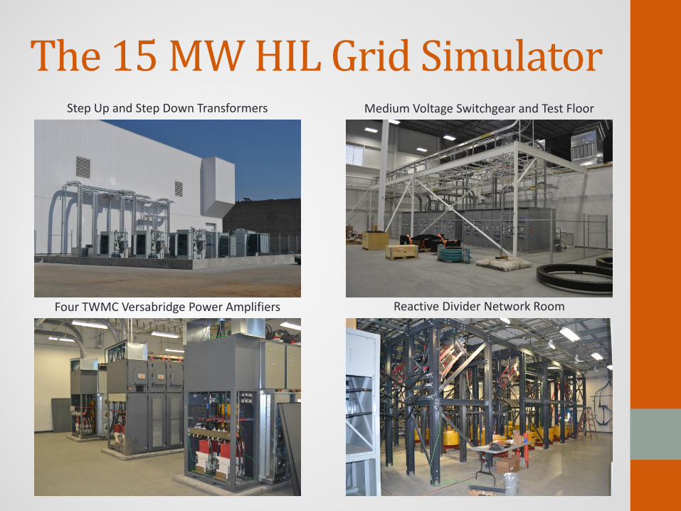
The 15 MW HIL Grid Simulator Step Up and Step Down Transformers Medium Voltage Switchgear and Test Floor
Four TWMC Versabridge Power Amplifiers Reactive Divider Network Room

• Power Set Points • Voltage and Frequency Variations • Controls Evaluation
Steady State and Envelope Evaluations
• Voltage Flicker • Harmonic Evaluations • Anti-Islanding (Software)
Power Quality Evaluations
• Frequency Response • Active Volt-VAR Control • Active Frequency Regulation
Ancillary Services
• Low Voltage Ride-Through (LVRT) • Unsymmetrical Fault Ride-Through • High Voltage Ride-Through (HVRT)
Grid Fault Ride-Through Testing
• Recreation of field events with captured waveform data Open Loop Testing
• Simulated dynamic behavior and interaction between grid and the device under test
Hardware-In-the-Loop Testing
Grid Integration Evaluations Increasing level of difficulty

Hardware-in-the-Loop Testing 15 MVA Series Connected National Instruments
H-Bridge Power Amplifiers Interface Controller Commanded Voltage
RTDS®
Voltage and Current Set Point Commands
Real Voltage and Current Measurements
BUS #N Voltage and Current
Information
Device Under Test “I’m connected at Bus #N”
Real Voltages associated with BUS #N
Reference
Loop timing and latency are critical

Energy Storage Integration M
odel
of a
Phy
sical
Sys
tem

Sim
ulat
ed G
rid a
t EG
RID
Mod
el o
f a P
hysic
al S
yste
m
Energy Storage Integration

Adding Distributed Control Hardware and Communications
Sim
ulat
ed G
rid a
t EG
RID
Mod
el o
f a P
hysic
al S
yste
m
Feeder Circuit IEDs
Transmission and SCADA IEDs
Real or Simulated IED Control and Response

TECO Westinghouse Motor Company:Power Amplifier Units
16
TWMC Power Amplifier Installed Power 20 MVA (15 MW @ 0.8 PF) Rated Power 15 MVA (12 MW @ 0.8 PF) Cabinet Power Split 4 x 3.75 MVA or 2 x 7.5 MVA Rated Voltage 0 - 4160 V Overvoltage 133 % Rated Output Voltage Multilevel Operation 7 - Levels (9 - Levels Overvoltage) Frequency Range 3 - 66 Hz Overload Capability 110% for 60 s (10 min duty cycle)
A
C
B
Isolation Transformer
Active Front End Input DC Bus Single Phase
Output
Individual power cube with three phase input and single phase output
VA
VB
VC
N
4 Power Slices per Amplifier Section
8 Parallel Amplifiers arranged into 4 Cabinets

Simulations and FAT testing show excellent results with 2 kHz switching frequencies
First noise mode is at 16 kHz (Fs x 2 x Carriers) , 8 times the switching frequency
Reference resolution also at 12 kHz using asymmetrical sampling
~260th
Harmonic
Frequency (10’s kHz)
TECO Westinghouse Motor Company:Power Amplifier Units • Phase Shifted Carrier PWM
• High degree of harmonic cancelation due to multilevel architecture
• Increased reference sampling fidelity • Sampling fidelity is further
increased by using asymmetrical sampling of each individual carrier
Synchronous Sampling up to 12 kHz Power Amplifier Output Harmonic Spectrum (Fs = 2 kHz)

Power Amplifier Units Commissioning Data
PAU Cube output switching frequency parameter set to 2 kHz

Fault-Ride Through (FRT) Requirements
•ABB Factory Testing (2009) •FGH Test Systems Field Testing (2006)
Reactive Divider Network Method
•GE Power Conversion (Fr. Converteam) •Vestas V164 Test Bench (2013) •NAREC 15 MW Test Bench (Hybrid?) (2014?) •ABB Test Systems •NWTC at NREL (4Q-2013)
Voltage Source Converter Method
•Clemson University (4Q-2014)
A Hybrid Method
World Wide FRT Withstand Curves
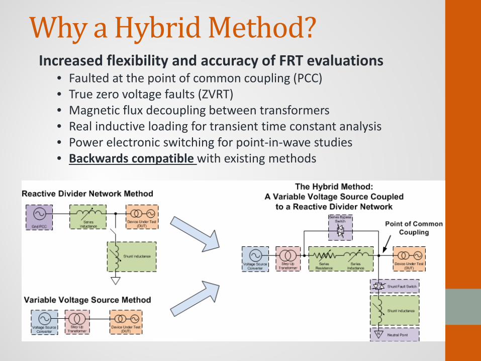
Why a Hybrid Method? Increased flexibility and accuracy of FRT evaluations
• Faulted at the point of common coupling (PCC) • True zero voltage faults (ZVRT) • Magnetic flux decoupling between transformers • Real inductive loading for transient time constant analysis • Power electronic switching for point-in-wave studies • Backwards compatible with existing methods

The Hybrid Method:Operation Cycle The Operation Cycle 1. Open Series
Bypass Switch 2. Close Shunt
Fault Switch 3. Open Shunt
Fault Switch 4. Close Series
Bypass Switch
There are only three unique system states in the operation cycle.
State 2
State 1 State 3
State 2

Reactive Divider Network • Safety Considerations
– Access controlled room – Automatic grounding system when not in service
• Voltage Isolation – 35 kV insulation system – 2500 A (100 MVA) DUT fault duty
• Performance and Flexibility – Remote control of all elements allows for setup
and operation without the need for room access – Individual phase operation allows for thousands
of three phase impedance combinations
Table of Fixed Reactance Combinations
Fixed Switch Positions
Shunt Fixed (mH)
Series Fixed (mH)
Total Shunt (mH)
Total Series (mH)
1-1-1-0 0 25 0-25 25-50 1-1-0-0 0 50 0-25 50-75 1-0-0-0 0 75 0-25 75-100 0-1-1-1 25 0 25-50 0-25 0-1-1-0 25 25 25-50 25-50 0-1-0-0 25 50 25-50 50-75 0-0-1-1 50 0 50-75 0-25 0-0-1-0 50 25 50-75 25-50 0-0-0-1 75 0 75-100 0-25
Table of Fixed Reactance Combinations
Reactive Divider Network • Safety Considerations
– Access controlled room – Automatic grounding system when not in service
• Voltage Isolation – 35 kV insulation system – 2500 A (100 MVA) DUT fault duty
• Performance and Flexibility – Remote control of all elements allows for setup
and operation without the need for room access – Individual phase operation allows for thousands
of three phase impedance combinations

Reactive Divider Network Commissioning Characteristics of the 60 kV VDRM SCR AC switches
Fiber optically coupled phase independent firing signals
Turn on times using FO triggering are near the rated turn on time of individual SCRs at just over 5 µs
Commissioning tests included:
Verification of each switch firing in situ with a VARIAC and ACR
Using one PAU and momentarily loading the PAU with the complete RDN inductive load

Modified Architecture: Direct FPGA to FPGA communication, more deterministic for controls
eGRID SCADA System • Detailed specifications developed through coordinated efforts between:
Savannah River Clemson National National Laboratory University Instruments
• Significant amount of hardware and software shared with the WTDTF systems • Provides a powerful and flexible platform for the development of custom control
systems to meet the various grid integration evaluation scenarios
applications.

Next Up: TWMC Controlled DC Supply Front End
• Modify a single TWMC PAU cabinet to provide the DC supply without control changes
• Aimed at solar testing with Maximum Power Point Tracking and 2D PV field simulation
• Partial bi-directional power flow (dynamic braking resistors) allows for tight regulation
• A novel control system will be used on existing NI PXI/FPGA hardware to integrate with the SCADA system
Voltage Range
Current Rating
Short Circuit Current
Ripple Frequency
Reverse Power Flow
DC Supply Module Specifications
1 Module 6 Modules
200 – 1000 V
420 A (1000 V) 2500 A (1000 V)
835 A 5000 A
2400 – 4800 Hz
67 kW (1000 V) 400 kW (1000 V)