Embed Size (px)
Citation preview
Effectiveness of seismic retrofit for stone masonry structures
V. Kilar1 & D. Marušić2 1Faculty of Architecture, University of Ljubljana, Slovenia 2Dinamika–Ideja–Prostor Ltd. (Dipstor), Ljubljana, Slovenia
Abstract Theis paper analyses the effectiveness of various seismic retrofitting techniques for the renovation of stone masonry structures. The first part of the paper summarizes the most widely used principles for strengthening of buildings made of natural stone units or a mixture of mortar and natural stone aggregate. In the second part of the paper some selected retrofitting techniques are applied for the structural and seismic renovation of a historical object (church built around 1570 located in Solčava in Slovenia). Before 2006 the church was critically cracked and not unsuitable for use. The retrofitting study made by the authors included the mandatory and recommended measures that should have taken place immediately, to prevent the settling down of the foundations and the increase of seismic resistance of the church. To date only partial strengthening of the foundations has taken place. The behavior of the church in various renewal stages was verified with computer program analysis with a very refined 3D computer model of the church. Three models were analyzed: a) a model of the existing church including the settling down of the SE wall, b) a model of the existing church after the partial retrofitting of the foundations in 2006 and c) a model as b), including the minimum suggested retrofitting proposals. Keywords: stone masonry structures, structural retrofit, seismic retrofit, seismic resistance, historical object, church building.
1 Overview of the methods for seismic retrofit of historical stone masonry structures
The cracks, subsiding of foundations and inadequate horizontal stiffness are among the most common causes that call for structural/seismic retrofit of historical buildings. The seismic strengthening of the building requires not only
Structural Studies, Repairs and Maintenance of Heritage Architecture X 687
© 2007 WIT PressWIT Transactions on The Built Environment, Vol 95, www.witpress.com, ISSN 1743-3509 (on-line) doi:10.2495/STR070641
the increase of stiffness, but also the increase of ductility of the individual elements as well as the structure as a whole. The increase of the stiffness is generally related to the increase of earthquake forces and can produce an unfavorable result if the ductility is not increased along with the stiffness. Special attention should be given to partial reconstruction measures where the increase of stiffness of one element might cause the unfavorable redistribution of internal forces during an earthquake. The retrofitting proposals should therefore always be supported with adequate numerical analyses, which prove the effectiveness of proposed measures. Some most widely used retrofitting measures for stone masonry objects are briefly summarized.
Retrofitting of the foundations • Consolidation of the foundations with the injection of cement-silicate mixture
(might include also hydrophobic additives). • Widening of the existing foundations. • Injecting of concrete under foundations and filling the voids under them. • Injecting of expansion materials and lifting of the foundations. • Solutions with pile systems, etc.
Strengthening of stone masonry walls • Injecting of cement-silicate mixture into the hollow middle part of the wall
with moderate pressure (up to 2 bar). • Concreting of RC concrete plaster enclosed and anchored to old wall. • Adding of the vertical RC confining elements. • Adding of vertical steel prestressed cables. • Strengthening of walls with plastic ribbons or textile bands made of GFRP
(Glass Fiber Reinforced Polymer) or more expensive CFRP (Carbon Fiber Reinforced Polymer).
• Some development has been made also in the field of seismic isolation with seismic bearings and dampers which activate only during stronger earthquakes.
Interconnection of walls • The interconnection of walls with horizontal steel bars anchored to steel plates. • Adding of horizontal confining RC elements. • Insertion of corner triangular stone elements and injecting of walls. • Adding of steel ribbons and injecting.
Retrofitting of arches • Injecting of cracks. • Rebuilding of damaged parts. • Removing of heavy filling and fabricating of RC plate. • Filling with reinforced aero-concrete. • Strengthening of arches with composite polymer ribbons.
2 Analyzed stone masonry church
2.1 Description of church in Solčava
The church of “Marija Snežna” was built in the second half of the 15th century (Fig. 1(left)). In past centuries it was repaired several times, and according to our
688 Structural Studies, Repairs and Maintenance of Heritage Architecture X
© 2007 WIT PressWIT Transactions on The Built Environment, Vol 95, www.witpress.com, ISSN 1743-3509 (on-line)
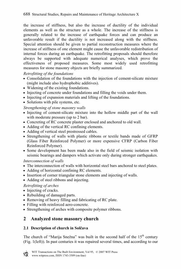
information the last time it was repaired thoroughly was in 1824. The arch thickness is constant and it amounts to 37 cm. The thickness of walls varies from 72, 87, 110 and 120 cm. Today the church is heavily cracked; we can see wide cracks of walls on the outer and inner sides as well as cracks in arches and stone groins (Fig. 1(middle)). The main reason is the subsiding of the NE wall of the main nave and presbytery (side opposite to bell tower), which has weaker foundations than other parts of the church. As a primary rescue measure we first demanded the strengthening of the foundations in order to prevent the threatening vault collapse (partly completed at the end of 2006). Other recommended retrofit measures are described and discussed in the last part of the paper.
Figure 1: Church in Solčava (Slovenia): photos and mathematical model.
1,50 0,19
320
Compression strength
Tensile strength
E
1,50 0,19
600
1000 MPa
100 MPa
10 MPa
1 MPa 0
wall arch wall arch wall arch
90
G
90
wall arch bearing capacity
Ground
0,20
100 kN/m3
10 kN/m3
1 kN/m3
0
22
Specific weight
24
wall arch
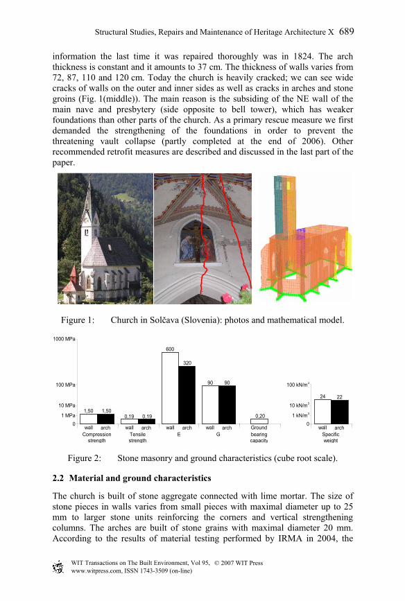
Figure 2: Stone masonry and ground characteristics (cube root scale).
2.2 Material and ground characteristics
The church is built of stone aggregate connected with lime mortar. The size of stone pieces in walls varies from small pieces with maximal diameter up to 25 mm to larger stone units reinforcing the corners and vertical strengthening columns. The arches are built of stone grains with maximal diameter 20 mm. According to the results of material testing performed by IRMA in 2004, the
Structural Studies, Repairs and Maintenance of Heritage Architecture X 689
© 2007 WIT PressWIT Transactions on The Built Environment, Vol 95, www.witpress.com, ISSN 1743-3509 (on-line)
compression strength of lime mortar varies from 1,0 – 1,5 MPa for the walls and from 1,5 – 2,0 MPa for the vaults and tower (Leskovar, 2004). Based on these data and obtained moisture gravimetrical measurements (ranging from 6.2 to 10.6%), the compression and tension strengths and elastic and shear modulus of walls and arches have been estimated. These values were further compared with the recommendations given by Tomaževič (1987). In our analysis we have used the average values obtained from both sources. The used material characteristics are summarized in Fig. 2. The allowable ground stress obtained from the geotechnical report amounts to 200 kPa.
2.3 Mathematical model
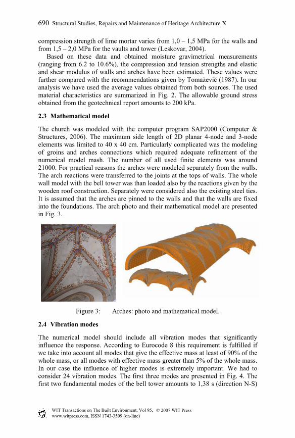
The church was modeled with the computer program SAP2000 (Computer & Structures, 2006). The maximum side length of 2D planar 4-node and 3-node elements was limited to 40 x 40 cm. Particularly complicated was the modeling of groins and arches connections which required adequate refinement of the numerical model mash. The number of all used finite elements was around 21000. For practical reasons the arches were modeled separately from the walls. The arch reactions were transferred to the joints at the tops of walls. The whole wall model with the bell tower was than loaded also by the reactions given by the wooden roof construction. Separately were considered also the existing steel ties. It is assumed that the arches are pinned to the walls and that the walls are fixed into the foundations. The arch photo and their mathematical model are presented in Fig. 3.
Figure 3: Arches: photo and mathematical model.
2.4 Vibration modes
The numerical model should include all vibration modes that significantly influence the response. According to Eurocode 8 this requirement is fulfilled if we take into account all modes that give the effective mass at least of 90% of the whole mass, or all modes with effective mass greater than 5% of the whole mass. In our case the influence of higher modes is extremely important. We had to consider 24 vibration modes. The first three modes are presented in Fig. 4. The first two fundamental modes of the bell tower amounts to 1,38 s (direction N-S)
690 Structural Studies, Repairs and Maintenance of Heritage Architecture X
© 2007 WIT PressWIT Transactions on The Built Environment, Vol 95, www.witpress.com, ISSN 1743-3509 (on-line)
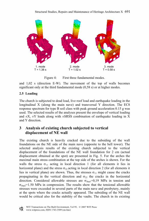
1. mode 2. mode 3. mode
T = 1.38 s T = 1.02 s T = 0.58 s
Figure 4: First three fundamental modes.
and 1,02 s (direction E-W). The movement of the top of walls becomes significant only at the third fundamental mode (0,58 s) or at higher modes.
2.5 Loading
The church is subjected to dead load, live roof load and earthquake loading in the longitudinal X (along the main nave) and transversal Y direction. The EC8 response spectrum for type B soil class with peak ground acceleration 0.15 g was used. The selected results of the analyses present the envelope of vertical loading and ±X, ±Y loads along with ±SRSS combination of earthquake loading in X and Y direction.
3 Analysis of existing church subjected to vertical displacement of NE wall
The existing church is heavily cracked due to the subsiding of the wall foundations on the NE side of the main nave (opposite to the bell tower). The selected analysis results of the existing church subjected to the vertical displacement of the foundations of the NE wall foundation for 2 cm (actual displacement obtained at the spot) are presented in Fig. 5. For the arches the maximal main stress combination at the top side of the arches is shown. For the walls the stress σ11 acting in local direction 1 (for all elements it lies in horizontal plane) and the stress σ22 acting in local direction 2 (for all elements it lies in vertical plane) are shown. Thus, the stresses σ11 might cause the cracks propaginating in the vertical direction and σ22 the cracks in the horizontal direction. Considered allowable stresses are σdop1=0,19 MPa in tension and σdop2=1.50 MPa in compression. The results show that the tensional allowable stresses were exceeded in several parts of the main nave and presbytery, mainly at the spots where the cracks actually appeared. The subsiding of the NE wall would be critical also for the stability of the vaults. The church in its existing
© 2007 WIT PressWIT Transactions on The Built Environment, Vol 95, www.witpress.com, ISSN 1743-3509 (on-line)
Structural Studies, Repairs and Maintenance of Heritage Architecture X 691
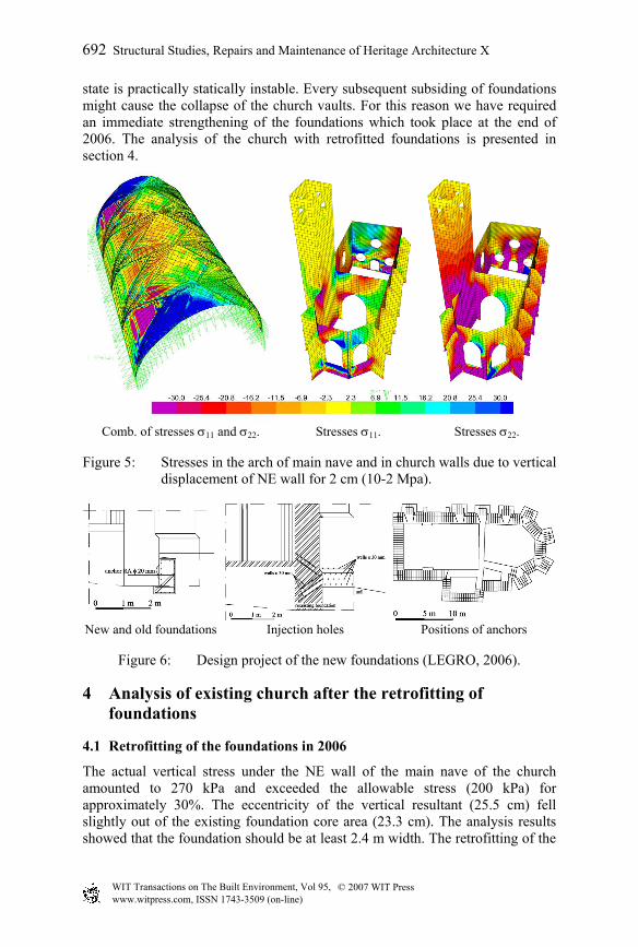
state is practically statically instable. Every subsequent subsiding of foundations might cause the collapse of the church vaults. For this reason we have required an immediate strengthening of the foundations which took place at the end of 2006. The analysis of the church with retrofitted foundations is presented in section 4.
Comb. of stresses σ11 and σ22. Stresses σ11. Stresses σ22.
Figure 5: Stresses in the arch of main nave and in church walls due to vertical displacement of NE wall for 2 cm (10-2 Mpa).
New and old foundations Injection holes Positions of anchors
Figure 6: Design project of the new foundations (LEGRO, 2006).
4 Analysis of existing church after the retrofitting of foundations
4.1 Retrofitting of the foundations in 2006
The actual vertical stress under the NE wall of the main nave of the church amounted to 270 kPa and exceeded the allowable stress (200 kPa) for approximately 30%. The eccentricity of the vertical resultant (25.5 cm) fell slightly out of the existing foundation core area (23.3 cm). The analysis results showed that the foundation should be at least 2.4 m width. The retrofitting of the
692 Structural Studies, Repairs and Maintenance of Heritage Architecture X
© 2007 WIT PressWIT Transactions on The Built Environment, Vol 95, www.witpress.com, ISSN 1743-3509 (on-line)
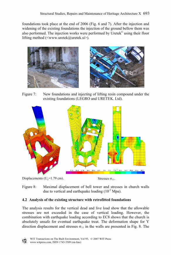
foundations took place at the end of 2006 (Fig. 6 and 7). After the injection and widening of the existing foundations the injection of the ground bellow them was also performed. The injection works were performed by Uretek using their floor lifting method (<[email protected]>).
Figure 7: New foundations and injecting of lifting resin compound under the existing foundations (LEGRO and URETEK. Ltd).
Displacements (Uy=1.79 cm). Stresses σ11.
Figure 8: Maximal displacement of bell tower and stresses in church walls due to vertical and earthquake loading (10-2 Mpa).
4.2 Analysis of the existing structure with retrofitted foundations
The analysis results for the vertical dead and live load show that the allowable stresses are not exceeded in the case of vertical loading. However, the combination with earthquake loading according to EC8 shows that the church is absolutely unsafe for eventual earthquake treat. The deformation shape for Y direction displacement and stresses σ11 in the walls are presented in Fig. 8. The
Structural Studies, Repairs and Maintenance of Heritage Architecture X 693
© 2007 WIT PressWIT Transactions on The Built Environment, Vol 95, www.witpress.com, ISSN 1743-3509 (on-line)
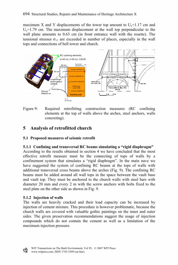
maximum X and Y displacements of the tower top amount to Ux=1.17 cm and Uy=1.79 cm. The maximum displacement at the wall top perpendicular to the wall plane amounts to 0.63 cm (in front entrance wall with the rosette). The tensional stresses σ11 are exceeded in number of places, especially in the wall tops and connections of bell tower and church.
RC confining elements;
w=40 cm, h=50 cm, C25/30
Existing wall
Longitudinal reinforcement: 12RΦ18
Stirrups: RΦ8/25 cm
Anchors: Φ20/50 cm
10-15 cm
Reinforcing mesh Q386
40 cm
50 cm
Concrete confinment
Steel plates400x400x8 mm
Arch top
Anchors: Φ25/200 cm
Anchors: Φ20/50 cm
Figure 9: Required retrofitting construction measures (RC confining elements at the top of walls above the arches, steel anchors, walls concreting).
5 Analysis of retrofitted church
5.1 Proposed measures of seismic retrofit
5.1.1 Confining and transversal RC beams simulating a “rigid diaphragm” According to the results obtained in section 4 we have concluded that the most effective retrofit measure must be the connecting of tops of walls by a confinement system that simulates a “rigid diaphragm”. In the main nave we have suggested the system of confining RC beams at the tops of walls with additional transversal cross beams above the arches (Fig. 9). The confining RC beams must be added around all wall tops in the space between the vault base and vault top. They must be anchored to the church walls with steel bars with diameter 20 mm and every 2 m with the screw anchors with bolts fixed to the steel plate on the other side as shown in Fig. 9.
5.1.2 Injection of walls The walls are heavily cracked and their load capacity can be increased by injection of cement mixture. This procedure is however problematic, because the church walls are covered with valuable gothic paintings on the inner and outer sides. The given preservation recommendations suggest the usage of injection compounds which do not contain the cement as well as a limitation of the maximum injection pressure.
694 Structural Studies, Repairs and Maintenance of Heritage Architecture X
© 2007 WIT PressWIT Transactions on The Built Environment, Vol 95, www.witpress.com, ISSN 1743-3509 (on-line)
5.1.3 Retrofitting of arches and groins The main arches and groins/ribs will be stabilized by proposed confining RC beams (5.1.1), which will accommodate all horizontal reactions of the arches. In this way the vaults, which primarily act in compression, will remain stable. One of the options for strengthening of the arches is also the usage of carbon ribbons, however the ribbons do not adhere easily to stone masonry units. As another option we might plan also the fabrication of thin concrete shell above the existing arches that can be supported by external walls. This proposal might be contradictory to already mentioned conservatory requirements.
5.1.4 Vertical confining elements The seismic response of the church could be further improved by adding of reinforced concrete vertical confining elements, which would increase the ductile wall behavior as well as enable a direct transfer of horizontal forces to the foundations. The vertical confining elements are however difficult to be built without the roof removal or without interventions in visual wall surface. One of the alternative options would be to build in the vertical steel rods (e.g. prestressed cables) and fix them to the steel plates at the wall tops and anchor them to the foundations.
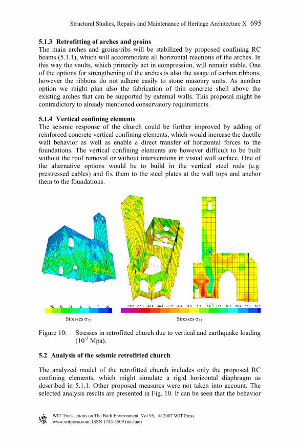
Stresses σ22 Stresses σ11
Figure 10: Stresses in retrofitted church due to vertical and earthquake loading (10-2 Mpa).
5.2 Analysis of the seismic retrofitted church
The analyzed model of the retrofitted church includes only the proposed RC confining elements, which might simulate a rigid horizontal diaphragm as described in 5.1.1. Other proposed measures were not taken into account. The selected analysis results are presented in Fig. 10. It can be seen that the behavior
Structural Studies, Repairs and Maintenance of Heritage Architecture X 695
© 2007 WIT PressWIT Transactions on The Built Environment, Vol 95, www.witpress.com, ISSN 1743-3509 (on-line)
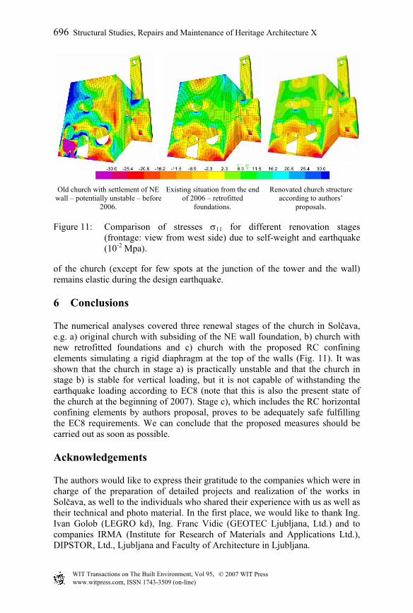
Old church with settlement of NE
wall – potentially unstable – before 2006.
Existing situation from the end of 2006 – retrofitted
foundations.
Renovated church structure according to authors’
proposals.
Figure 11: Comparison of stresses σ11 for different renovation stages (frontage: view from west side) due to self-weight and earthquake (10-2 Mpa).
of the church (except for few spots at the junction of the tower and the wall) remains elastic during the design earthquake.
6 Conclusions
The numerical analyses covered three renewal stages of the church in Solčava, e.g. a) original church with subsiding of the NE wall foundation, b) church with new retrofitted foundations and c) church with the proposed RC confining elements simulating a rigid diaphragm at the top of the walls (Fig. 11). It was shown that the church in stage a) is practically unstable and that the church in stage b) is stable for vertical loading, but it is not capable of withstanding the earthquake loading according to EC8 (note that this is also the present state of the church at the beginning of 2007). Stage c), which includes the RC horizontal confining elements by authors proposal, proves to be adequately safe fulfilling the EC8 requirements. We can conclude that the proposed measures should be carried out as soon as possible.
Acknowledgements
The authors would like to express their gratitude to the companies which were in charge of the preparation of detailed projects and realization of the works in Solčava, as well to the individuals who shared their experience with us as well as their technical and photo material. In the first place, we would like to thank Ing. Ivan Golob (LEGRO kd), Ing. Franc Vidic (GEOTEC Ljubljana, Ltd.) and to companies IRMA (Institute for Research of Materials and Applications Ltd.), DIPSTOR, Ltd., Ljubljana and Faculty of Architecture in Ljubljana.
696 Structural Studies, Repairs and Maintenance of Heritage Architecture X
© 2007 WIT PressWIT Transactions on The Built Environment, Vol 95, www.witpress.com, ISSN 1743-3509 (on-line)
References
[1] Computers and Structures, Inc. SAP 2000 Nonlinear, Version 10. Computers and Structures, Inc: Berkeley, California, USA, 2006.
[2] Eurocode 8. Design of structures for earthquake resistance Part 1: General rules, seismic actions and rules for buildings, European Standard EN 1998-1: 2004. CEN, European Committee for Standardization.
[3] Leskovar I, Grčar S, Šušteršič J. Poročilo o preiskavah kamnitih zidov na objektu farna cerkev Marije Snežne, Solčava. IRMA d.o.o. Ljubljana: Ljubljana, 2004 (Materiel investigation report).
[4] Tomaževič M. Zidane zgradbe na potresnih območjih. Univerza Edvarda Kardelja v Ljubljani, Fakulteta za arhitekturo, gradbeništvo in geodezijo: Ljubljana, 1987.
[5] Vidic F. Geotehnično poročilo o pregledu razpok, opredelitvi zemljin ter predlogu sanacije temeljenja cerkve Marije Snežne v Solčavi. GEOTEC Ljubljana, d.o.o., Ljubljana, 2004 (Geotechnical report).
Structural Studies, Repairs and Maintenance of Heritage Architecture X 697
© 2007 WIT PressWIT Transactions on The Built Environment, Vol 95, www.witpress.com, ISSN 1743-3509 (on-line)
![injecting [ 2 ] › pdf › HRDVD5.pdf · when you stop injecting, things seldom return to normal. The information in this booklet aims to reduce the harms of injecting by helping](https://img.dokumen.tips/doc/110x75/5f0c9cd87e708231d4364591/injecting-2-a-pdf-a-hrdvd5pdf-when-you-stop-injecting-things-seldom.jpg)