Embed Size (px)
Citation preview

Effectiveness of Geotextiles in Reducing Levels of Soil Restraint
for Buried Pipelines Crossing Seismic Faults
MANUEL MONROY, M.Sc. (Eng.) Geotechnical Consultant, Golder Associates Ltd., Vancouver, BC
DHARMA WIJEWICKREME, Ph.D., P. Eng. Professor, University of British Columbia, Vancouver, BC.
DOUGLAS HONEGGER, M.S. President, D.G. Consulting, Arroyo Grande, CA, USA. ABSTRACT A series of tests were carried out to evaluate the effectiveness of geosynthetic fabrics as a mitigation option. Full-scale models of geotextile-lined pipeline trenches were constructed in an improved version of the Advanced Soil Pipe Interaction Research (ASPIRe) soil chamber. Lateral and oblique soil restraints arising from strike-slip and reverse faults, respectively, were simulated by applying relative soil-pipe displacements in appropriate directions. Results evidence that lateral soil restraint is not constant, increases with displacement, and could be higher than those obtained from configurations with no trenches. Vertical oblique soil restraint response show a peak followed by a displacement softening behaviour. The results of the tests suggest that the shear resistance is not controlled by the geotextile interface, but rather by the geotextile-soil interface or by the backfill. This characteristic makes the benefit of using two layers of geotextile fabric minimal, and, therefore, its use should be discouraged.
Introduction
The performance of buried pipelines to earthquake effects depends on mobilized levels of soil restraint, as soil-structure interaction occurs due to permanent and transient ground deformations. Soil restraints depend on the direction and level of relative displacement between the buried pipeline and its surrounding soil and the amount of deformation of the soil surrounding the pipe. Soil restraints can induce bending, shear, tension, or compression demands on segments of buried pipeline systems.
Lateral soil restraint, like the one imposed by a lateral
strike-slip fault, is one of the most studied cases of soil-structure interaction for pipeline systems. It is based upon a relatively large number of laboratory, numerical, and field experimental investigations on pipe response in buried sand, and also upon studies on related structures (e.g., piles, anchor plates, and strip footings). Charts and theoretical procedures to estimate lateral maximum strength in the soil are available and based on frictional properties of the soil and appropriate failure surfaces (Hansen 1961, Trautmann and O’Rourke 1983, O’Rourke et al. 2008, PRCI 2004). For reverse/thrust fault crossing designs, vertical oblique pipe-soil restraint properties are seldom available in current published technical literature and are usually inferred in practice on the basis of horizontal and vertical soil restraints.
In tectonically active regions, it is common to find a
large level of demands imposed onto pipeline systems that may lead to the exceedance of established pipeline performances. When confronted with these technical problems, it is usual to consider mitigation options to reduce soil restraints on buried pipelines and, therefore, increase their capacity.
Current seismic design guidelines (PRCI 2004)
recommend the use of geosynthetic fabrics as a means to reduce soil restraints on buried pipelines based largely upon the low interface frictional properties of the geosynthetic fabrics. However, the effectiveness of this technique is currently poorly understood, and little guidance is available to permit more complete specifications on installation requirements and define methods for quantifying reductions in soil restraint.
A comprehensive research program was conducted at
the University of British Columbia (UBC) to investigate the effectiveness of geotextile-lined pipeline systems using full-scale physical modeling. The side slope of a pipeline trench with a trapezoidal cross-section (usually called a trench wall) lined with two layers of geosynthetic materials was built for this purpose in a large soil chamber. The size of the trapezoidal trench had typical dimensions and inclinations used in current field practice. The trench was backfilled using selected backfill material after the placement of the pipe segment chosen for testing. In addition to studying the effectiveness of geotextile-lined trench walls, the effect of the presence of the trench wall on the development of levels of lateral soil restraint was also investigated.
In the chamber, lateral horizontal and vertical oblique
displacements were applied to steel pipe specimens to simulate pipeline breakout from its soil embedment during lateral strike-slip and reverse faults scenarios, respectively. In these full scale tests, loads and displacements of the pipe were measured and soil failure mechanisms were investigated. Geotextile displacement was also recorded and evaluated in the context of soil-pipe interaction.

Experimental tests
Tests were performed using an improved version of the Advanced Soil Pipe Interaction Research (ASPIRe) soil chamber that exists at the University of British Columbia (Monroy 2013). The new test apparatus allows investigating soil restraint-displacement behaviour of buried pipe configurations arising from a variety of directions of relative pipe movements (from horizontal/ lateral to vertical pipe displacements). The internal plan dimensions of the soil chamber measure approximately 2.5 m x 4.0 m and provide for up to 2 m of soil cover above the test pipe.
The new chamber includes large Plexiglas panels that
allow direct visual observation of sectional views of different test configurations, development of soil failure surfaces, and relative movement between soil and pipe specimen during tests. A general arrangement of the chamber is shown in Fig. 1.
The investigation of the role of geotextiles as a
mitigation measurement requires the reproduction of specific geometrical, material, and boundary conditions that exist at a project site. Therefore, a full-scale shallow trapezoidal trench was carefully constructed inside the soil
chamber. The trench has side wall slopes of 35 and 45 to the horizontal, and was lined with dual layers of TC Mirafi Filterweave 700 woven geotextile fabric. Only the outer geotextile layer (in contact with backfill material) was allowed to move. Direct shear tests on the dual layer of
geotextile fabric showed a peak friction angle of 20±1. A hard/stiff native trench was simulated by using well-
compacted 19 mm minus well-graded crushed sand and gravel lined with a timber support system. Sand-blasted pipe specimens with 2.4 m length and 457 mm (NPS18) and 406 mm (NPS16) diameters were used for the tests. The thickness of all pipe specimens was 1.27 mm.
With respect to backfill materials, two scenarios were reproduced. One scenario represents a medium-dense (average dry density of about 1600 kg/m
3) condition that
was simulated by using uniformly-graded, moist Fraser River sand with a moisture content of 3 to 5%. Sand was selected in order to provide a baseline case, and by comparison of our tests with published soil restraint values in no trench configurations, where appropriate. The second scenario represents a condition in which sand material is not available at the project site, and “real” soil materials must be used. A mixture of 19 mm minus crushed sand and gravel (road mulch) with average dry density of about 1800 kg/m
3 and 19 mm minus crushed limestone with an
average dry density of about 1700 kg/m3 was selected for
this purpose. Fraser River sand was extensively used and
documented during numerous element laboratory research programs performed at UBC in the past. The results of those investigations indicate an average grain size, D50, of 0.3 mm, a minimum particle size of 0.074 mm, and a specific gravity (Gs) of 2.70. The constant volume of internal friction angles range from 32° to 34°. The peak
friction angle at a dry density of 1600 kg/m3 is 43. Large
direct shear tests (0.3 m x 0.3 m) on the crushed sand and gravel and on the crushed limestone showed average peak
friction angles of 49º and 51, respectively. Direct shear tests on the geotextile-moist sand and the geotextile-crushed sand and gravel interfaces showed a peak friction
angle of 31±1. Approximately 23 m
3 of soil material is typically required
to fill the soil test chamber for a test. The test chamber was filled by dumping the backfill material using a tipping hopper car attached to a forklift. Once the soil material was deposited, it was spread within the soil test chamber, forming lifts of 300 mm that were later compacted with a hand-pushed static roller. The mass density of the backfill material was measured at random locations during the filling process using a calibrated nuclear densometer. In addition, the density of the compacted backfill was verified
Fig. 1. Perspective view of the testing chamber and general arrangements for tests
35 o
r 45
Outer geotextile
Mirafi Filterweave 700
H/D
= 1
.9
NP
S18 o
r N
PS
16
Framing system
Timber support system
Trench wallBackfill
PVC pipe
Pulling cable for
strike-slip scenarios
To actuators
X
Z
Inner geotextile
Mirafi Filterweave 700 (fixed)
Pulling cable for
reverse fault scenarios
strong soil to simulate
hard native boundary conditions

using mass-volume measurements taken from aluminium bowls placed within the fill prior to compaction. Upon completion of a given test, the material was removed through an opening located at the rear of the soil test chamber.
The coupling system for lateral strike-slip fault type
tests consisted of end clamps at each end of the pipe combined with 29 mm steel cables and shackles. The 29 mm cables were directly attached to the clamps and passed through PVC pipes between the trench wall and vertical slots in one of the ends of the test chamber wall. The pipes and vertical slots were provided to allow free vertical movement of the cables in the event of vertical pipe uplift during the tests.
For reverse fault displacement tests, the coupling
system consisted of diametric rods passing through each pipe end and attached to steel cables. The direction and inclination of the steel cables were set up according to the slope of the thrust fault using a set of sheaves mounted on vertical steel columns. This mechanism simulates the oblique angle breakout of the buried pipe from the trench backfill on the footwall side of a fault at an angle similar to the fault thrust angle. In all cases, the loading system did not interfere with the movement of the pipe.
Each cable was then connected to a load cell mounted
on double-acting hydraulic actuators with a digital hydraulic control system. The capacity of the actuators is 418 kN at 21 MPa working pressure. The hydraulic actuators, manufactured by Royal Cylinders Inc., had a 200 mm bore diameter with a full stroke of ±305 mm and a 90 mm rod diameter. The load cells were MTS model 661.22, with a maximum load capacity of 225 kN.
Pipe displacements relative to the soil test chamber were measured using string potentiometers. For strike-slip fault displacement tests, 1.6 mm diameter steel cables were attached to both back ends of the pipe. The cables were passed through small-diameter PVC pipes embedded in the soil and connected to string potentiometers mounted outside and at the back of the test chamber. For reverse fault tests, string potentiometers (SP) were attached to the pulling cables with two inclinometers and a set of eight SPs for the measurement of the pulling angle.
The displacement of the outer geosynthetic fabric layer
was measured through an additional set of potentiometers. Very thin extension cables were attached to the bottom of the outer geosynthetic fabric layer and to string potentiometers that were buried below the pipe invert. All measurements from the instrumentation array monitoring the pipe specimens were recorded at 20 Hz (20 samples per second).
Experimental work
A total of 16 tests were conducted to assess the performance and effectiveness of geotextiles in reducing levels of soil restraint on buried pipelines. Geotextile-lined pipeline trenches and plain cases (no trench) were constructed in full-scale dimensions. Lateral and oblique soil restraints, arising from lateral strike-slip and reverse fault scenarios, were simulated by providing relative soil-
pipe displacements in the horizontal, 35, and 45 directions. Details and characteristics of the tests are shown in Table 1.
Table 1. Testing array for the experimental work
ID Pipe
Diameter H/D
Backfill Material Trench
wall angle
Pulling direction
(degrees)1
Distance pipe to trench
Geotextile Sand
Sand and
gravel
Crushed limestone
T1 NPS18 1.9 45 0 0.5D No
T2 NPS18 1.9 45 0 0.5D Yes
T3 NPS18 1.9 45 0 1D Yes
T4 NPS18 1.9 45 0 2D Yes
T5 NPS18 1.9 NC 0 NC No
T6 NPS18 1.9 45 0 0.5D Yes
T7 NPS18 1.9 45 0 0.5D Yes
T8 NPS18 1.9 35 0 0.5D Yes
T9 NPS18 1.9 35 0 0.5D Yes
T10 NPS18 1.9 NC 0 NC No
T11 NPS18 1.9 NC 0 NC No
T12 NPS16 1.6 NC 45 NC No
T13 NPS16 1.6 45 45 0.5D No
T14 NSP16 1.6 45 45 0.5D Yes
T15 NPS16 1.6 45 35 0.5D No
T16 NSP16 1.6 45 35 0.5D Yes
NC = Not considered 1 Angle with respect to horizontal

Test results
The test pipes were loaded in a displacement-controlled manner at a rate of 2.5 mm/s. The loading rates have no noticeable effect on the results (Karimian 2006). For all tests, the total load per unit length on the pipe was determined by adding the load measured from each load cell and dividing it by the length of the pipe specimen (2.4 m). Symmetry of the pulling system was verified by controlling the difference in recorded readings from each load cell to be less than 5%.
The normalized lateral soil restraint (Nqh), normalized
vertical oblique soil restraint (Nvo), and normalized displacement (Y’) are presented in the form
[1] HD
P N h
qh
[2] HD
P N vo
vo
[3.a] D
Y Y' ; [3.b]
D
YG GY'
where Ph is the measured horizontal load per unit length,
Pvo is the measured vertical oblique load per unit length, is the dry unit weight of the backfill, D is the pipe diameter, H is the height of soil over the pipe springline, and Y and YG are the recorded pipe and geotextile displacements, respectively. The form of the normalized load and displacement, shown above, follows the relationships presented in previous research about lateral soil restraint (Hansen 1961, Audibert and Nyman 1977, Trautman and O’Rourke 1983, and PRCI 2004).
Lateral pipe displacement The development of soil restraint as relative lateral displacement of the pipe specimen progresses, for test configurations with the lined trench and no geotextile lining, T1 and T2, respectively, is shown in Fig. 2. Three regions can be distinguished: initial linear response (Region 1), plateau (Region 2), and post-plateau work hardening (Region 3). Region 1 extents up to about 0.002D to 0.003D. Region 2 represents the observed constant lateral soil restrain between Y’ of about 0.05D to 0.3D to 0.4 D. Region 3 represents the nonlinear increase of lateral soil restraint on the pipe after Y’ of 0.3D to 0.4D.
The data from Fig. 2 evidences that a fairly constant
reduction of about only 15% can be obtained for the lateral soil restraint along the plateau. The limited benefit observed for mitigation configurations, based on geotextile-lined trenches and the development of an increase in lateral soil restraint at large pipe displacements, wasalso reported by Karimian et al. (2006). Their results are shown in Fig. 2 for reference and comparison purposes.
Further tests were conducted to investigate the effect of
the trench wall on the mechanical behaviour during soil-pipe interaction. Tests T3 and T4 were carried out with a trench wall-pipe distance (S) of 1D and 2D, respectively. In addition, a plain test on moist sand was conducted (T5) with the aim of quantifying the level and development of
lateral soil restraint, and therefore isolate the effect of trench wall on the lateral soil restraint-displacement relationship. The results of such tests are presented in Fig. 3 together with the results from T2. It can be observed that soil-pipe response from tests T3, T4, and T5 are remarkably similar and only T3 produces a nonlinear load-displacement increase after pipe displacements of about 0.6D (about twice the pipe displacement of 0.3D for the onset of load increase after the plateau observed in T2).
Fig. 2. Lateral soil restraints in sloped trench walls (moist
sand) due to lateral strike-slip fault displacement.
Fig. 3. Effect of trench wall-pipe distance (S) on levels of
soil restraints.
The results from Fig. 3 evidence that a different failure
mechanism controls the development of the plateau, and that the failure mechanism is a function of the trench wall-pipe distance (S). Furthermore, a boundary for defining
these mechanisms can be traced at S = 1D. For S 1D, the soil-pipe interaction is controlled entirely by the frictional properties of the backfill soil, and its plateau (and also ultimate) lateral soil restraint could be quantified by limit-based equilibrium approaches based on a log-spiral failure surface like that proposed by O’Rourke et al. (2008).

Fig. 4 illustrates the position of the log-spiral failure surface developed during T4 (S = 2D) with respect to the geotextile-lined trench wall, and evidences that the lateral restraint is imposed only by the soil. The log-spiral model (O’Rourke et al. 2008) predicts an Nqh of 8.1 for the moist
sand backfill ( = 43, = 12). Displacement for the outer geotextile was recorded for T4.
From Fig. 3 and Fig. 4, it can be concluded that for the
geotextile to be “effective”, the trench-wall pipe distance (S) has to be less or around 0.5D and therefore its behaviour will be controlled by the frictional properties along the sloped trench wall.
Soil deformations for test T2 (S=0.5D) after Y’=0.05D
(Region 2) and Y’=0.45D (Region 3) are illustrated in Fig. 5.a and 5.b, respectively. Clearly, different failure surfaces or modes of instability developed as the pipe mobilized Nqh values through these regions. In Region 2 (Figure 5.a), most of the appreciable shear deformation appears to be occurring along the edges of a passive wedge configuration, while the soil mass in front of the pipe and inside the wedge showed no significant shear deformation
By contrast, in Region 3 the soil mass inside the wedge
showed significant shear deformation (Figure 5.b) which occurred after the pipe started to move upward with an
inclination of about 30 to 35 from the horizontal. This vector may have developed due to the interaction between
the imposed lateral displacement and the 45 boundary condition of the sloped trench wall. This mode of instability appears to represent a soil response governed by shearing through the backfill soil as the pipe moves upward and shearing of a compressed soil mass due to the proximity of the pipe to the trench wall. This mode also shows the development of several different active zones of soil failure.
PRCI (2004) guidelines recommend the use of two
layers of geosynthetic fabric as a means to reduce lateral soil restraint under the premise that a low-friction failure surface will be developed along the sloped trench wall (one edge of the passive wedge configuration). The validity of this premise can be evaluated from the data presented in
Fig. 6 that shows the development of Nqh and the displacement of the outer geotextile as a function of time.
Fig. 5. Failure modes for geotextile-lined pipeline trenches
– strike-slip fault displacements (a) after Y’=0.05D, and (b)
after Y’=0.45D. Note that grid on Plexiglas is 0.1 x 0.1 m.
Fig. 4. Log-spiral failure surface developed for trench wall-pipe distance S = 2D (grid 0.1 x 0.1 m).
Pipe lateral
displacement
= 0.05D
Passive soil wedge
H/D = 1.9 Lined
trench
wall
(a)
Zones of soil
failure
30 - 35
Pipe upward
displacement
at least 0.26D
Pipe lateral
displacement =
0.45D
(b)
45 geotextile-lined
Trench Wall
Assumed log-
spiral failure
surface

Fig. 6. Evolution of lateral soil restraint and geotextile
displacement as a function of time for T2.
The Nqh level required to overcome the geotextile
friction can be obtained by identifying the time above which the outer geotextile slides. From Fig. 6, this time is 40 s and the Nqh is about 3.4. However, the response of the soil-pipe system has not reached the plateau in terms of Nqh, but rather, it is still in a process of additional soil restraint development. The data from Fig. 6 indicates that the plateau load is not associated with simply an intact passive wedge sliding along the low-friction geotextile fabrics interface. This suggests that deformations within the backfill soil may be mobilizing the shear resistance along the soil-outer geotextile interface, the next resistance mechanism along the trench wall surface.
The results from test on a stronger backfill material
(mixture of sand and gravel) are presented in Fig. 7. Tests T6 and T7 were carried out with a lined trench wall with a slope of 45 degrees from the horizontal; while tests T8 and T9 were conducted on a lined trench wall with a slope of 35 degrees. Tests T10 and T11 were tests without trench. Test T7, T9, and T11 were done for repeatability purposes and quality control of the soil-pipe interaction response.
The soil restraint versus pipe displacement results from
tests with a mixture of sand and gravel backfill (Fig. 7) display a response similar to tests with moist sand in that there are three regions. However, the effectiveness of geofabrics in reducing the plateau lateral soil restraint imposed on the pipe is more noticeable for the mixture of sand and gravel backfill. For Region 2 (Y’ of about 0.2D), a reduction of about 33% and 45% of lateral soil restraint was obtained for the cases of geotextile-lined trench walls of 45° and 35°, respectively. As the Nqh moved into Region 3, the reduction vanished; and as the shape of the load-displacement suggests, the lateral soil restraint could be even higher than those obtained from the plain case (Nqh greater than 11).
Similar to the case of sand backfill, the response of the
soil-pipe system for the mixture of sand and gravel backfill had not reached the plateau in terms of Nqh when the outer geotextile slid, as shown in Fig. 8 for tests T8 and T9.
Fig. 7. Lateral soil restraints in sloped trench walls (road
mulch) due to lateral strike-slip fault displacement
Fig. 8. Evolution of lateral soil restraint and geotextile
displacement for T8 and T9.
Vertical oblique pipe displacement The effectiveness of geotextiles in reverse fault scenarios were evaluated by simulating the oblique angle breakout of a buried pipe on the footwall side of a fault at an angle
similar to 35 and 45 fault thrust angles. The results
obtained for 45 and 35º fault thrust angles are shown in Fig. 9 (Tests T12, T13 and T14) and Fig. 10 (Tests T15 and T16), respectively. Only T12 did not include a sloped trench wall and was done with moist sand as backfill material. T13, T14, T15 and T16 were carried out with a 45º sloped trench wall. Soil deformation and inferred failure surface for T16 is shown in Fig. 11.
The soil restraint-displacement relationships showed continuous increase of soil restraint with displacement until a peak value was reached. Then, a displacement softening behaviour appeared as the pipe moved to the surface. This behaviour suggests that the shear resistance is through the backfill material only, even though geotextile displacement was observed. Similar to the pipe cases under lateral displacement, comparison of the test results suggest that
the benefit of lining a sloped trench wall with geofabrics is relatively minimal.
Fig. 9. Vertical oblique soil restraints due to reverse fault
displacement -T12, T13 and T14.
Fig. 10. Vertical oblique soil restraints due to reverse fault
displacement -Tests T15 and T16.
Fig. 11. Failure mode for geotextile-lined pipeline trenches
at Y’=1.0D - Reverse fault displacement – T16.
Analytical study of data trends
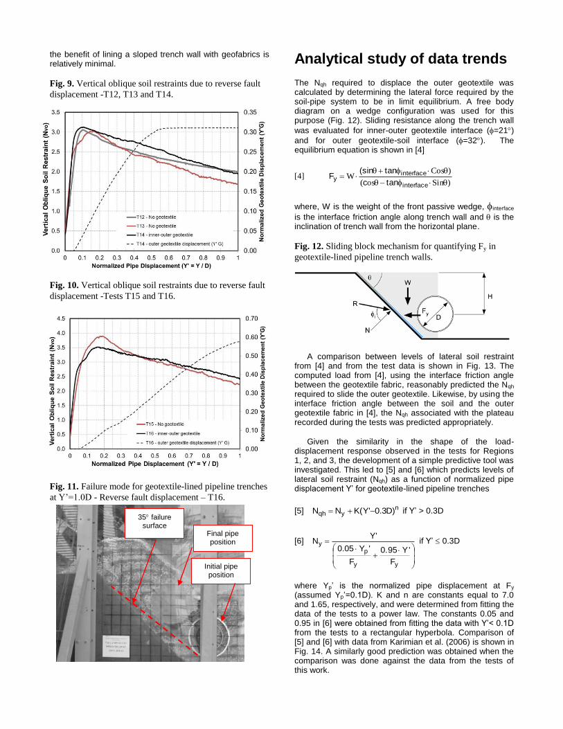
The Nqh required to displace the outer geotextile was calculated by determining the lateral force required by the soil-pipe system to be in limit equilibrium. A free body diagram on a wedge configuration was used for this purpose (Fig. 12). Sliding resistance along the trench wall
was evaluated for inner-outer geotextile interface (=21)
and for outer geotextile-soil interface (=32). The equilibrium equation is shown in [4]
[4] )Sinos(
)CosW
interface
interfacey
tanc
tan(sin F
where, W is the weight of the front passive wedge, interface
is the interface friction angle along trench wall and is the inclination of trench wall from the horizontal plane.
Fig. 12. Sliding block mechanism for quantifying Fy in
geotextile-lined pipeline trench walls.
A comparison between levels of lateral soil restraint
from [4] and from the test data is shown in Fig. 13. The computed load from [4], using the interface friction angle between the geotextile fabric, reasonably predicted the Nqh required to slide the outer geotextile. Likewise, by using the interface friction angle between the soil and the outer geotextile fabric in [4], the Nqh associated with the plateau recorded during the tests was predicted appropriately.
Given the similarity in the shape of the load-
displacement response observed in the tests for Regions 1, 2, and 3, the development of a simple predictive tool was investigated. This led to [5] and [6] which predicts levels of lateral soil restraint (Nqh) as a function of normalized pipe displacement Y’ for geotextile-lined pipeline trenches
[5] nyqh )D3.0'Y(KN N if Y’ > 0.3D
[6]
yy
py
F
Y'.950
F
'Y05.0
'Y N if Y’ 0.3D
where Yp’ is the normalized pipe displacement at Fy (assumed Yp’=0.1D). K and n are constants equal to 7.0 and 1.65, respectively, and were determined from fitting the data of the tests to a power law. The constants 0.05 and 0.95 in [6] were obtained from fitting the data with Y’< 0.1D from the tests to a rectangular hyperbola. Comparison of [5] and [6] with data from Karimian et al. (2006) is shown in Fig. 14. A similarly good prediction was obtained when the comparison was done against the data from the tests of this work.
35 failure surface
Initial pipe position
Final pipe position

Fig. 13. Comparison between lateral soil restraints from the
tests and from [4].
Fig. 14. Lateral soil restraint relationship from [5] and [6]
vs. data from Karimian et al. (2006)
Conclusions
A series of tests were carried out to evaluate the effectiveness in reducing the levels of soil restraint of geotextile-lined pipeline trenches crossing seismic faults. For geotextile-lined pipeline trenches under strike-slip fault displacements, the dual geotextile plays a role in the levels and development of lateral soil restraint only if the pipe-
trench wall distance (S) is less than 0.5D. If S 1D, the lateral soil restraint is controlled by the shear resistance of the backfill.
Three regions can be distinguished from the lateral soil
restraint versus pipe displacement relationship if S 0.5D. Patterns of soil deformation suggest that Regions 1 and 2 are associated with a soil wedge configuration. The Nqh value required to slide the outer geotextile was predicted by a limit equilibrium analysis when the friction angle between geotextiles was used. Likewise, the Nqh at the plateau was appropriately predicted when the friction angle between soil and outer geotextile was used. This suggests that deformations within the backfill soil mobilized the soil-
geotextile friction angle during the tests and poses questions to the effectiveness of dual geotextiles as a mitigation measurement. Furthermore, test results for the soil-pipe system under lateral displacement showed that, for Y’ larger than 0.3D (Region 3), the level of soil restraint could be higher than those from configurations with no trenches.
For pipeline trenches under reverse fault displacement,
no appreciable difference was found between the vertical oblique soil restraint in cases with geotextile and without geotextile. This behaviour suggests that the shear resistance is through the backfill material even though geotextile displacement was observed.
The use of two layers of geotextile fabric as a means of
mitigation measurement for pipes crossing strike-slip or reverse seismic faults should be discouraged or its use limited to conditions governed by small relative soil-pipe displacements.
Acknowledgement
The funding for this study was provided by Pipeline Research Council International and is gratefully acknowledged. Thanks are also due to Messrs. S. Jackson, D. Smith, H. Shrempp, D. Lee and A. Critchley.
References
Audibert, J.M.E. and Nyman, K.J. 1977. Soil Restraint Against Horzontal Motion of Pipes. Journal of the Geotechnical Engineering Division. ASCE, 103, No. GT10, 1119-1142.
Hansen, J.B. 1961. The ultimate resistance of rigid piles against transversal forces. Danish Geotechnical Institute, Denmark. Bulletin 12.
Karimian H., Wijewickreme D., Honneger D. 2006. Full-scale laboratory testing to assess methods for reduction of soil loads on buried pipes subject to transverse ground movement. 6
th International
Pipeline Conference. Proceeding of IPC 2006 - 10047. Monroy, O. M. 2013. Soil Restraint on Steel Buried
Pipelines Crossing Active Seismic Faults. Ph.D. Thesis. University of British Columbia, Canada.
O’Rourke T.D., Jezerski J. M., Olson N. A., Bonneau A.L., Palmer M.C., Stewart H.E., O’Rourke M. J. 2008. Geotechnics of pipeline system response to earthquakes. Geotechnical Soil Engineering and Soil Dynamics. Proceedings of the Geotechnical Earthquake Engineering and Soil Dynamics IV (181).
Pipeline Research Council International (PRCI). 2004. Guidelines for Natural Gas and Liquid Hydrocarbon Pipelines in Areas Prone to Landslide and Subsidence Hazards. Catalog No. L52292.
Trautmann, C. H., and O’Rourke, T. D. 1983. Behaviour of pipe in dry sand under lateral and uplift loading. Geotechnical Engineering Report 83-7, School Civil and Environmental Engineering, Cornell University.