Embed Size (px)
Citation preview

EFFECTIVE AREA FOR MASONRY
M.A. HatzinikolasH. Morstead

EFFECTIVE AREA FOR MASONRY
Introduction
The purpose of this technical note is to call attention to the variations in the
load resisting areas of masonry. External loads applied to masonry result in two basic
types of stresses, namely:
a) normal stresses
b) shearing stresses
Normal stresses basically result from vertical loads and/or bending moments. Shearing
stresses are commonly the result of lateral loads.
The level of stress, either normal or shearing, is a function of the applied
loads and the effective area. The effective area, in turn, is influenced by the type of
construction and the type of masonry units used.
As a result of the testing procedures used in evaluating strength of masonry,
the allowable stresses for plain masonry as given in Table 5 of the C.S.A. Standard
S-304-1977 "Masonry Design and Construction for Buildings"

2.
are based on the net cross-sectional area for compressive stresses resulting from
axial loads, and on the net section for all other types of stresses.
The allowable stresses (fm) for reinforced masonry
are given on Tables 6 and 7 of the above-mentioned document,
and they are based on the net cross-sectional area.
The compressive strength (fm') as given in the C.S.A.
Standard S-304 "Masonry Design and Construction for Buildings", is based on the net
cross-sectional area. The shear strength is based on the net section for plain
masonry and the net cross-sectional area for reinforced masonry.
The two very important parameters in masonry
design, - Net Cross-Sectional Area and Net Section, -
are defined as follows:
- Net cross-sectional area -- Average net crosssectional area of the
masonry unit plus the grouted area.
- Net section -- Minimum cross-section of the member under consideration.
Usually, the mortar bedded area plus the grouted area.
Effective Area for Axial Compressive Stress Calculations
This area considers the net cross-sectional area.
Figure a shows a partially grouted concrete masonry wall. The effective
area (shaded) consists of the net section of the masonry units plus the grouted
cores.

The Canadian Masonry Code 1 allows the use of the same net cross-
sectional area for running bond and stack bond types of construction. (In running
bond vertical joints are in alignment in every second course, whereas
in stack bond the vertical joints are alignment in
every course.) As a result the two walls shown schematically in Figure 1 have
the same effective area for resisting axial compressive stresses, although the net
section for the two walls is not the same. (This aspect is examined
in the following section.)
The effective area for walls consisting of two
core concrete block units is given in Table 1. This area is to be used for
evaluation of the allowable vertical
load only. Note that this table is valid for running bond, stack bond, fully bedded
or face shell bedding types of construction.
The values listed in Table 1 have been arrived at
as follows:
Consider the wall shown in Figure la and in particular the two full blocks
shown on top of the wall. The wall is an 8 in. block grouted at 16 in. on centre.
The net cross-sectional area of this wall portion is:
2(16.Q X 2 X 1.25) + 2(5.125 X 1.25 X 3)
+ 2(5.125 X 6.125) � 185.6 in. 2

4.
TABLE 1 Effective Area for Resisting Axial Compressive Stresses
Nominal Wall Thickness 6 in. 8 in. 10 in. 12 in.
Net Cross-Sectional Area in 2 /in
Solid Grouted 5.6 7.6 9.6 11.6
16 in. o.c. 4.5 5.8 7.2 8.5
24 in. o.c. 4.1 5.2 6.3 7.5
32 in. o.c. 3.9 4.9 5.9 7.0
40 in. o.c. 3.8 4.7 5.7 6.7
48 in. o.c. 3.7 4.6 5.6 6.5
No Grout in Wall 3.4 4.0 4.8 5.5

(a) Effective area for compressive stress calculations
in running bond type of construction.
(b) Effective area for compressive stress calculations
in stack bond type of construction
FIGURE 1 Effective Area for Compressive
Stress Calculations
5.

6.
The net cross-sectional area per inch of this wall is:
185.6 in. 2
32 =
.. 5. 8 in. 2
in.
In the above calculations the face shell and the web thicknesses of the masonry
units were taken to be 1.25 in.
Effective Area for Flexural Stress Calculation
a) Plain Masonry
Flexural stresses are resisted by the net section, that is, by the mortar
and the grouted cores (where applicable) .
In the case of two core blocks this area is the face shell only if
running bond type of construction is used. For stack bond the flexural stresses
are resisted by the net cross-sectional area. This discrepancy arises because of
the misalignment of the webs in running bond, whereas in stack bond the webs
line up, thus increasing the area resisting bending stresses (stack bond fully
bedded type of construction.) Plate 1 illustrates the concept of web
misalignment.
b) Reinforced Walls
The flexural stresses in reinforced load bearing masonry are resisted by
the net cross-sectional area.

7.
PLATE 1 Web Misalignment in Running Bond Construction

8.
A designer who is conscious about "necking" in a, load path will
instinctively regard this as a discrepancy and inconsistent to the design approach.
In this case, however, the effect of .the "weak link" has, in the opinion of the
writers, already been included in the conservative allowable stress values in C. S. A. -
S-304.
For flexurai calculation, the following limitations are set by the Canadian
Code.
Where a masonry shear wall intercepts a loadbearing masonry wall to
form T or I sections the effective flange shall not exceed one-sixth of the total
wall height above any cross-section of the wall, and its overhanging width, on
either side of the shear wall shall not exceed six times the thickness of the
intercepted wall. C.C.I.7.5 S-3041, the ACI Standard "Building Code Requirements
for Concrete Masonry Structures"2 recommends that the total thickness of the
flange in T or I sections, is to be taken as 1/6 times the wall height of the
intersected wall.
Figure 2 illustrates the ACI recommendation for intercepting shear wails for a
number of conditions.
For flexural calculation it should be noted that the tensile forces in
reinforced masonry are resisted only by the tensile reinforcement, and that tensile
stresses parallel to bed joints are not permitted in stack pattern masonry unless
adequate reinforcement is provided.
(Articles 4.8.1.c and 4.s.1.2, C.S.A. S-304).

I-:c (!)
jjj :c
_J . _J
c(
:=:
EFFECTIVE FLANGE WIDTH � WALL HEIGHT x t
EFFECTIVE FLANGE
WID;H < WALL- HEIGHT X * .
1-:c (!)
jjj :c
_J _J
:
EFFECTIVE FLANGE WIDTH <. 12 x t1 + t2
I-:c Q LI.I
:c
_J _J
c(
:=:
1-:c (!)
jjj :c
_J _J c(
:=:
FLANGE
FIGURE 2 Intersecting Shear Walls
9.

10.
In computing flexural stresses in walls where reinforcement occurs,
the effective width shall be not greater than four times the wall thickness
(4.8.2.4 c.s.A. S-304-1977).
The Canadian Masonry Code does not differentiate between running
bond and stack bond patterns in establishing the effective width.
The ACI Code recommends the use of effective width equal to 6
times the wall thickness for running bond, and 3 times the wall thickness for
stack bond. The value recommended by C.S.A. Standard S-304 - 1977 is
within
the two values suggested by ACI. Figure 3 illustrates the ACI recommendations.
Effective Area for Shear Stress Calculations
a) Plain Masonry
Shearing stresses in plain masonry are resisted by the net section,
that is, by the mortar bedded area and the area of grouted cores. As a
result the effective area is influenced by the type of construction. The effective
area for shear calculation is given in Tables
2 and 3 for 6 in., 8 in., 10 in. and 12 in. two core
concrete blocks.
Table 2 is applicable to running bond type of construction and
Table 3 is applicable to stack bond construction and fully mortar bed types
of construction.

(a) Effective area for flexural stress calculations ingrouted core running bond masonry construction.
(b) Effective area for flexural stress calculations ingrouted core stack bond masonry construction.
FIGURE 3 Effective Area for Flexural
Stresses in Grouted Core Construction
11.

12.
TABLE 2 Net Section for Shear Calculations in Running Bond Type of Construction
(2 Core Concrete Block Units)
Nominal Wall Thickness 6 in. 8 in. 10 in. 12 in.
Net Section . 2; · in. in.
Solid Grouted 5.60 7.60 9.6 11.60
16 in. o.c. 3.20 5.00 5.2 6.40
24 in. o.c. 2.80 3.80 4.5 5.30
32 in. o.c. 3.60 3.45 4.1 4.70
40 in. o.c. 2.45 3.25 3.9 4.40
48 in. o.c. 2.40 3.15 3.7 4.15
No Grout in Wall 2.0 2.5 3.0 3.0
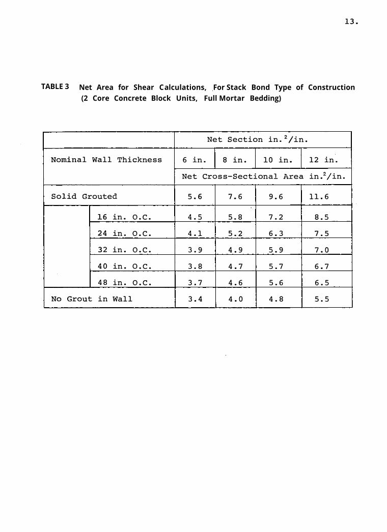
TABLE 3 Net Area for Shear Calculations, For Stack Bond Type of Construction (2 Core Concrete Block Units, Full Mortar Bedding)
Net Section . 2 /' in. in.
Nominal Wall Thickness 6 in. 8 in. 10 in.
Net Cross-Sectional Area
Solid Grouted 5.6 7.6 9.6
16 in. o.c. 4.5 5.8 7.2
24 in. o.c. 4.1 5.2 6.3
32 in. o.c. 3.9 4.9 5.9
40 in. o.c. 3.8 4.7 5.7
48 in. o.c. 3.7 4.6 5.6
No Grout in Wall 3.4 4.0 4.8
12 in.
. 2; • in. in.
11.6
8.5
7.5
7.0
6.7
6.5
5.5
13.

14.
It should be noted that for stack bond type of construction the effective
area for shear calculations is the same as the effective area for axial stress
calculations, that is, the net cross-sectional area. Note that there is no difference in
effective areas for running and stack bond and face shell mortar bedding.
b) Reinforced Masonry
In calculating the shearing stresses for reinforced masonry structural
elements, the resisting area according
to C.S.A. S-304 "Masonry Design and Construction for Buildings" is the net cross-
sectional area.
However, the maximum shearing stress is limited
to 50 psi, (for shear walls of reinforced concrete block construction). If this value
is exceeded the total shear shall be taken by the reinforcement and shall not exceed
150 psi for flexural member and 75 for shear walls.
For shear calculations in reinforced shear walls the effective areas are the
same as those given in Table 1.
It should be noted that only walls in the direction of the lateral force are
effective in resisting the resulting shearing stresses.
In grouted core construction shear is resisted by the grouted core plus the
surrounding mortared area and the cross webs. Figure 4 shows the effective area
for shear stress in grouted core construction.

(a) Effective area for shear along the wall in grouted masonry. (ACI recommendation)
(b) Effective area for shear perpendicular tothe wall in grouted masonry. (ACI recommendation)
FIGURE 4 Effective Area for Shear Calculations in Grouted Masonry
15.

16.
REFERENCES
1. C.S.A. Standard S-304-1977, "Masonry Design andConstruction for Buildings", Canadian Standards Association, 178 Rexdale Boulevard, Rexdale, Ontario, Canada, May 1977.
2. Building Code Requirements for Concrete MasonryStructures, Title No. 75-42 reported by ACI Committee S31, ACI Journal, August 1978.