Embed Size (px)
Citation preview
ECE 442 Power Electronics 1
DC-DC Converter Drives
• Principle of Power Control
• Principle of Regenerative Brake Control
• Principle of Rheostatic Brake Control
• Combined Regenerative and Rheostatic Brake Control
• Two and Four Quadrant DC – DC Converter Drives

ECE 442 Power Electronics 2
Converter-fed DC Drive for a Separately-Excited Motor
ECE 442 Power Electronics 3
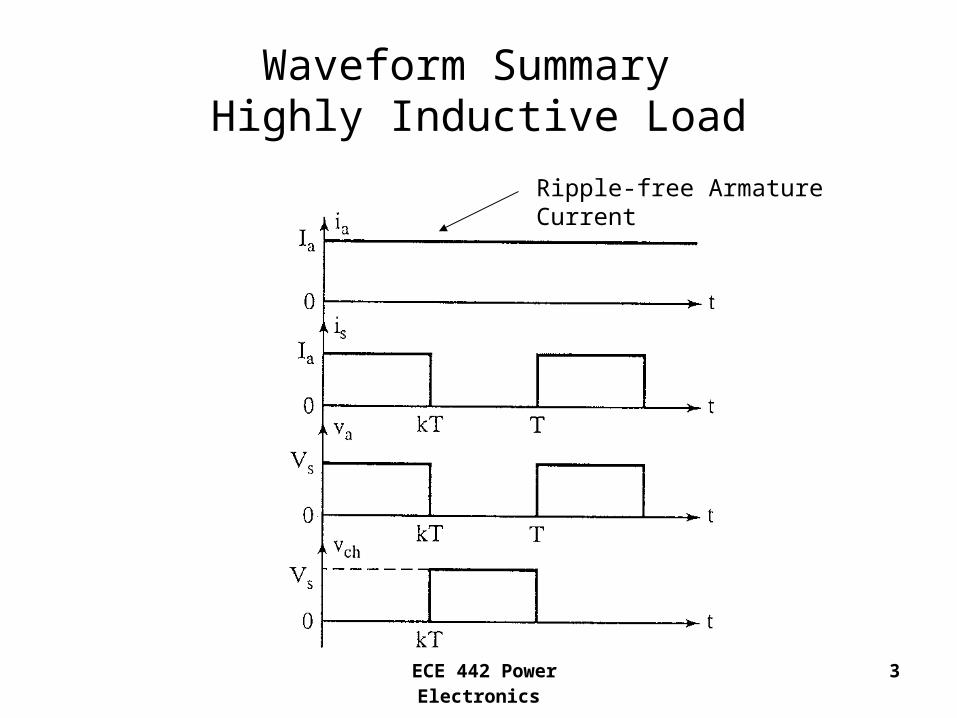
Waveform Summary Highly Inductive Load
Ripple-free Armature Current

ECE 442 Power Electronics 4
Principle of Power Control
• The average armature voltage is
• The power supplied to the motor is
sa kVV
asaao IkVIVP
ECE 442 Power Electronics 5
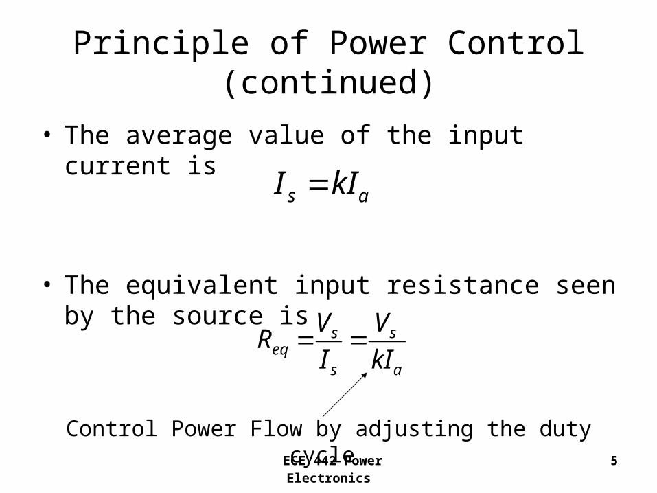
Principle of Power Control (continued)
• The average value of the input current is
• The equivalent input resistance seen by the source is
as kII
a
s
s
seq kI
V
I
VR
Control Power Flow by adjusting the duty cycle

ECE 442 Power Electronics 6
Principle of Power Control (continued)
• To find the maximum peak-to-peak ripple current
m
m
m
s
fL
R
R
VI
4tanhmax

ECE 442 Power Electronics 7
Example 15.7 A dc separately excited motor is powered by a dc-dc converter, as shown, from a 600V dc source. The armature resistance is Ra = 0.05Ω. The back emf constant is Kv = 1.527V/A rad/s. The average armature current is Ia = 250A. The field current is If = 2.5A. The armature current is continuous and has negligible ripple. If the duty cycle of the dc-dc converter is 60%, determine:
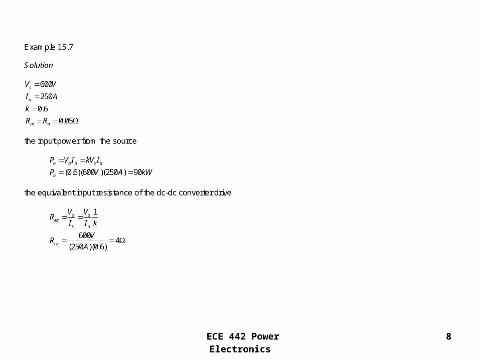
ECE 442 Power Electronics 8
Example 15.7 Solution
600
250
0.6
0.05
s
a
m a
V V
I A
k
R R
the input power from the source
(0.6)(600 )(250 ) 90o a a s a
o
P V I kV I
P V A kW
the equivalent input resistance of the dc-dc converter drive
1
6004
(250 )(0.6)
s seq
s a
eq
V VR
I I k
VR
A

ECE 442 Power Electronics 9
the motor speed
(0.6)(600 ) 360
360 (0.05 )(250 ) 347.5
347.591.03 /
(1.527 / / )(2.5 )
3091.03 869.3
g v f
g a m m
a s
g
g
v f
E K I
E V R I
V kV V V
E V A V
E Vrad s
K I V Arad s A
rpm
the developed torque
(1.527 / / )(250 )(2.5 ) 954.38
d t f a v f a
d
T K I I K I I
T V Arad s A A N m

ECE 442 Power Electronics 10
Application of a DC – DC Converter in Regenerative Braking

ECE 442 Power Electronics 11
Waveform SummaryArmature Current Continuous
and Ripple-Free

ECE 442 Power Electronics 12
Regenerative Braking
• Begin with the motor turning by kinetic energy of the vehicle
• Armature current flows as shown
• Turn the transistor on• Armature current rises• Turn the transistor off• Diode turns on, current
flows into the supply

ECE 442 Power Electronics 13
Principle of Regenerative Braking
• The average voltage across the transistor is
• The regenerated power can be found from
sch VkV )1(
)1( kVIP sag
ECE 442 Power Electronics 14
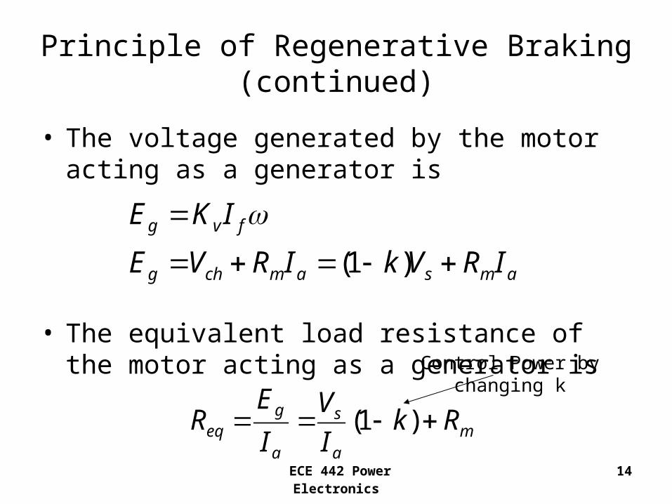
Principle of Regenerative Braking (continued)
• The voltage generated by the motor acting as a generator is
• The equivalent load resistance of the motor acting as a generator is
amsamchg
fvg
IRVkIRVE
IKE
)1(
ma
s
a
geq Rk
I
V
I
ER )1(
Control Power by changing k

ECE 442 Power Electronics 15max
max
max
min
min
min
)(0
fv
am
fv
s
samfv
fv
am
amfvg
samg
IK
IR
IK
V
VIRIK
IK
IR
IRIKE
VIRE
Minimum Braking Speed
Maximum Braking Speed

ECE 442 Power Electronics 16
Example 15.8 A dc-dc converter is used in regenerative braking of a dc series motor similar to the arrangement shown below. The dc supply voltage is 600V. The armature resistance is Ra = 0.02Ω and the field resistance is Rf = 0.03Ω. The back emf constant is Kv = 15.27mV/A rad/s. The average armature current is maintained constant at Ia = 250A. The armature current is continuous and has negligible ripple. If the duty cycle of the dc-dc converter is 60%, determine the following:
For this example, the field and armature need to be in series

ECE 442 Power Electronics 17
Example 15.8 Solution
600
250
0.01527 / /
0.6
s
a
v
m a f
V V
I A
K V Arad s
k
R R R
Determine the average voltage across the converter.
(1 )
(1 0.6)(600 ) 240ch s
ch
V k V
V V V
Determine the power regenerated to the dc supply
(1 )
(250 )(600 )(1 0.6) 60
g a s
g
P I V k
P A V kW
Determine the equivalent resistance of the motor acting as a generator
(1 )
0.02 0.03 0.05
600(1 0.6) 0.05 1.01
250
g seq m
a a
m a f
eq
E VR k R
I I
R R R
VR
A

ECE 442 Power Electronics 18
Determine the minimum permissible braking speed ωmin
min
min
0.05 2503.274 /
0.01527 / / 250
1 603.274 / 31.26
2 1min
m a
v f
R I Arad s
K I V Arad s A
rev srad s rpm
rad
Determine the maximum permissible braking speed ωmax
max
max
max
max
600 0.05
(0.01527 / / )(250 ) 0.01527 / /
160.445 /
30160.445 1532.14
s m a
v f v f
V R I
K I K I
V
V Arad s A V Arad s
rad s
rpm
Determine the motor speed
(1 ) 240 (0.05 )(250 ) 252.5
252.566.14 /
(0.01527 / / )(250 )
3066.14 631.6
gg v f
v f
g s m a
EE K I
K I
E k V R I V A V
Vrad s
V Arad s A
rpm

ECE 442 Power Electronics 19
Rheostatic Brake ControlDynamic Braking

ECE 442 Power Electronics 20
Waveform Summary

ECE 442 Power Electronics 21
Principle of Rheostatic Brake Control
• The average current in the braking resistor is
• The average voltage across the braking resistor is
)1( kII ab
)1( kIRV abb

ECE 442 Power Electronics 22
Principle of Rheostatic Brake Control (continued)
• The equivalent load resistance of the generator
• The power dissipated in the resistor Rb is
mba
beq RkR
I
VR )1(
)1(2 kRIP bab

ECE 442 Power Electronics 23
Example 15.9 A dc-dc converter is used in rheostatic braking of a dc separately excited motor as shown below. The armature resistance is Ra = 0.05Ω. The braking resistor is Rb = 5Ω. The back emf constant is Kv = 1.527V/A rad/s. The average armature current is maintained constant at Ia = 150A. The armature current is continuous and has negligible ripple. The field current is If = 1.5A. If the duty cycle of the dc-dc converter is 40%, determine:

ECE 442 Power Electronics 24
Example 15.9 Solution
150
1.527 / /
0.4
0.05
a
v
m a
I A
K V Arad s
k
R R
the average voltage across the dc-dc converter.
(1 )
(5 )(150 )(1 0.4) 450ch b b a
ch
V V R I k
V A V
the power dissipated in the braking resistor
2
2
(1 )
(150 ) (5 )(1 0.4) 67.5
b a b
b
P I R k
P A kW
the equivalent resistance of the motor acting as a generator
(1 )
(5 )(1 0.4) 0.05 3.05
beq b m
a
eq
VR R k R
I
R
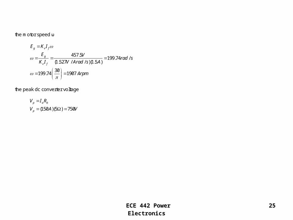
ECE 442 Power Electronics 25
the motor speed ω
457.5199.74 /
(1.527 / / )(1.5 )
30199.74 1907.4
g v f
g
v f
E K I
E Vrad s
K I V Arad s A
rpm
the peak dc converter voltage
(150 )(5 ) 750
p a b
p
V I R
V A V

ECE 442 Power Electronics 26
Combined Regenerative and Rheostatic Brake Control

ECE 442 Power Electronics 27
Combined Regenerative and Rheostatic Brake Control (continued)
• Used when the supply is partly “receptive”
• Remove regenerative braking if line voltage is too high– Turn thyristor TR on
– Divert current to RB
– Apply rheostatic braking
– TR is “self-commutated”

ECE 442 Power Electronics 28
Two-Quadrant DC–DC Converter Drive

ECE 442 Power Electronics 29
Quadrant Operation Summary
Regenerative Braking Control Power Control

ECE 442 Power Electronics 30
Power Control
• Q1 and D2 operate
• Q1 ON, Vs applied to the motor
• Q1 turned OFF, D2 “free-wheels”
• Armature current decays

ECE 442 Power Electronics 31
Regenerative Control
• Q2 and D1 operate
• Q2 turned ON, motor acts as a generator, and the armature current rises
• Q2 turned OFF, motor returns energy to the supply via D1 “free-wheeling”

ECE 442 Power Electronics 32
Four Quadrant DC-DC Converter Drive

ECE 442 Power Electronics 33
Quadrant Operation Summary
Forward Regeneration Forward Power Control
Reverse Power Control Reverse Regeneration

ECE 442 Power Electronics 34
Forward Power Control
• Q1 and Q2 turned ON
• Supply voltage appears across the motor
• Armature current rises
• Q1 and Q2 turned OFF
• Armature current decays via D3 and D4

ECE 442 Power Electronics 35
Forward Regeneration
• Q1, Q2, and Q3 turned OFF
• Turn Q4 ON
• Armature current rises and flows through Q4, D2
• Q4 turned OFF, motor acts as a generator, returns energy back to the supply via D1, D2
ia reverses

ECE 442 Power Electronics 36
Reverse Power Control
• Q3 and Q4 turned ON• Supply voltage appears
in the reverse direction across the motor
• Armature current rises and flows in the reverse direction
• Q3 and Q4 turned OFF• Armature current
decays via D1 and D2
ia
ECE 442 Power Electronics 37
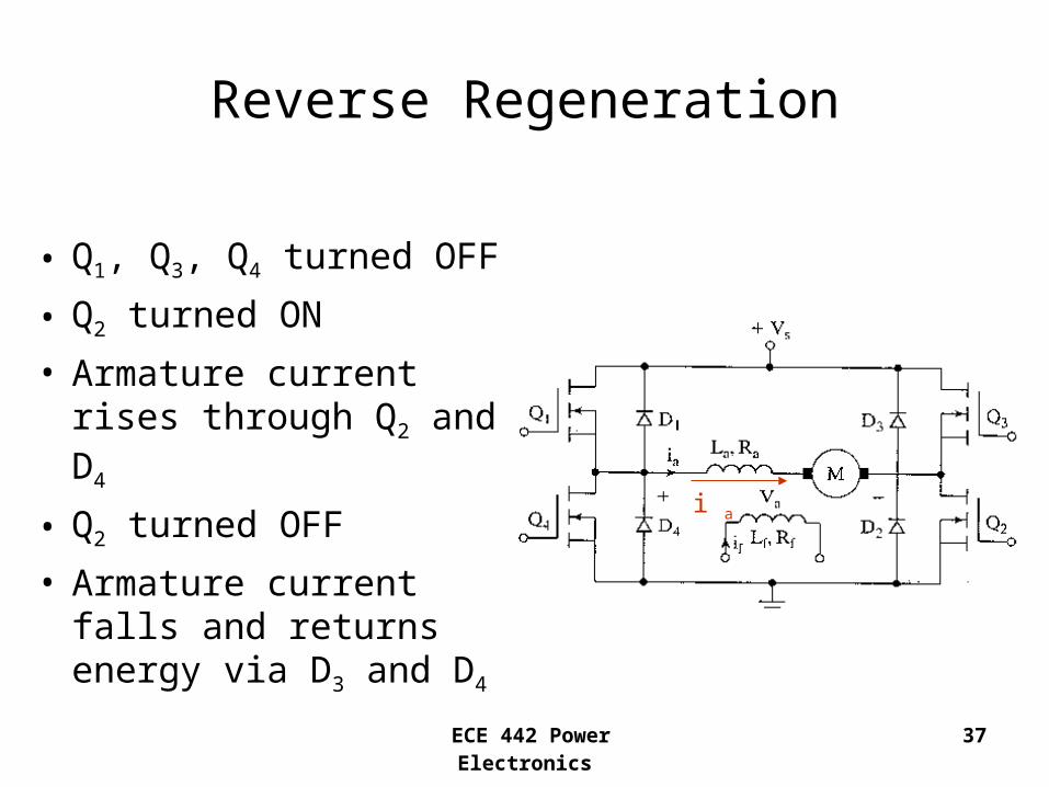
Reverse Regeneration
• Q1, Q3, Q4 turned OFF
• Q2 turned ON
• Armature current rises through Q2 and D4
• Q2 turned OFF
• Armature current falls and returns energy via D3 and D4
i a