Embed Size (px)
Citation preview

1
Sensotronic Brake Control(R230 SBC)
218 HO SBC (WJB) 09-30-02
2
These technical training materials are current as of the date noted on the materials, and may be revised or updated without notice.Always check for revised or updated information.
To help avoid personal injury to you or others, and to avoid damage to the vehicle on which you are working, you must always referto the latest Mercedes-Benz Technical Publication and follow all pertinent instructions when testing, diagnosing or making repair.Illustrations and descriptions in this training reference are based on preliminary information and may not correspond to the final USversion vehicles. Refer to the official introduction manual and WIS when available.Copyright Mercedes-Benz USA, LLC, 2002
WIS document numbers shown apply to WIS Version G.04.06 11/01 USA/CDN
Reproduction by any means or by any information storage and retrieval system or translation in whole or part is not permittedwithout written authorization from Mercedes-Benz USA, LLC or its successors.Published by Mercedes-Benz USA, LLCPrinted in U. S.A.

3
IndexIntroduction 4Advantages 5Components 8
Warning Display 10Brake Operating Unit (BOU) 12Pedal Value Sensor 14Hydraulic Unit (A/3) 18
Emergency Operation 19Pressure Supply 20ABS Control 21ASR, EBR, ESP Functions 22Temperature Compensation 23
Wake-up 24Predrive Check (PDC) 25Delayed Off 26Deactivation 27Activation 29Warning Buzzer 30Bleeding the system 31Acronyms 32

4
Evolution! ABS (Anti lock Brakes 1984)
+ ASR (Automatic Slip Regulation 1991)
+ ETS (Electronic Traction System 1994)
+ ESP (Electronic Stability Program 1996)
+ BAS (Brake Assist System 1998)
= SBC (Sensotronic Brake Control 2002)
SBC = Sensotronic Brake Control, the next level ofbrake control !
GF42.45-P-0001SL

5
Advantages of SBC• Improves metering of required brake pressure
– each wheel can be precisely controlled
• Improved BAS function
– monitors release of accelerator pedal & application of
brake
– maximum pressure available immediately
– Pre-filling of system (overcoming play)
– when the BAS function is anticipated (identified by the
rapid release of the gas pedal), slight pressure is
applied
GF42.46-P-0001SLGF42.46-P-2000SL
6
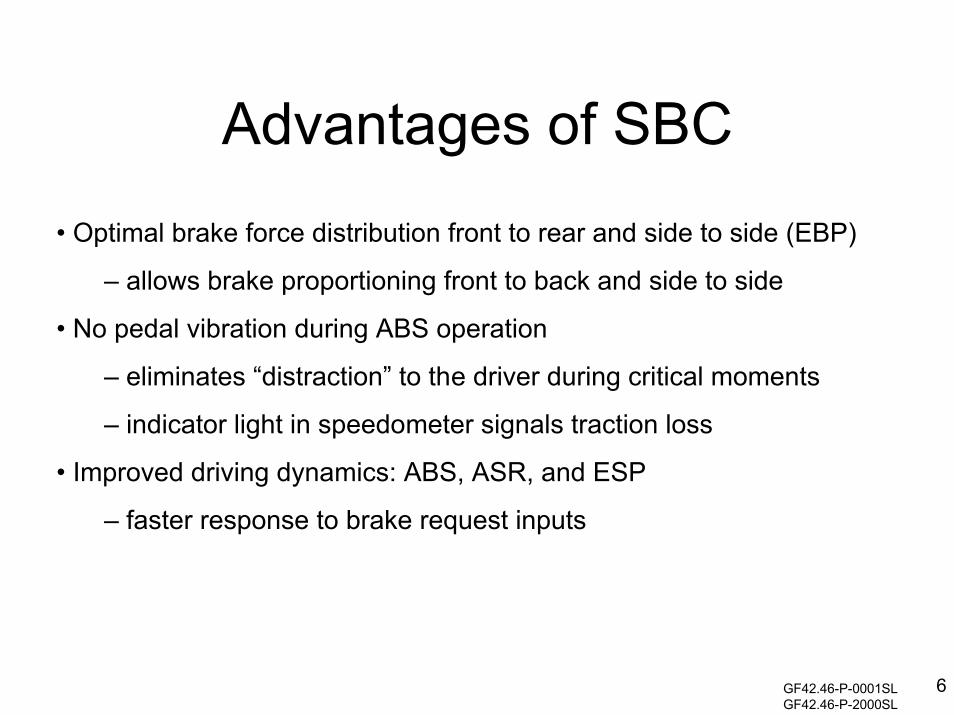
Advantages of SBC• Optimal brake force distribution front to rear and side to side (EBP)
– allows brake proportioning front to back and side to side
• No pedal vibration during ABS operation
– eliminates “distraction” to the driver during critical moments
– indicator light in speedometer signals traction loss
• Improved driving dynamics: ABS, ASR, and ESP
– faster response to brake request inputs
GF42.46-P-0001SLGF42.46-P-2000SL

7
Advantages of SBC• Softstop function
– comfort feature
– reduces brake pressure when coming to a stop (<.6
mph)
• Pressure reduction at standstill
– reduces stress on components
• Dry braking function
– wiper input via CAN
– ~every 7 to 14 minutes
– brake actuation changes
time intervalGF42.46-P-0001SLGF42.46-P-2000SL

8
SBC Components
• Brake Operating Unit (BOU) • Wheel speed sensors
• Traction System Hydraulic Unit A7/3

9
Wear SensorsThree brake pad wearsensors connected toclosest SAM
• Left front (S10/1)• Right front (S10/2)• Right rear (S10/4)

10
Warning Display
ESP control module failure
GF42.45-P-0001-04SL
If the ESP control module has a complete failure the dash will cycle through it’s displays(ABS, BAS, ESP). The SBC system is still functional but without any pressure modificationincluding brake proportioning.
Depending on the failure, all other systems that require a vehicle speed signal with also be in-operative. (Transmission in second gear, no SPS steering , etc.)

11
Warning Display
SBC control module failure
GF42.45-P-0001-04SL
If the SBC system shuts down, you default to the emergency braking mode, allvehicle speed related functions may also stop depending on the failure.Certain faults will trigger an audible signal.

12
Brake Operating Unit - (BOU)
GF42.46-P-4210SL

13
Brake Operating UnitThe Brake Operating Unit (BOU)consists of the following:
• Brake fluid reservoir (Do not overfill!)
• SBC pedal value sensor (B37/1)
• Tandem master cylinder
• Brake pressure simulator
GF42.46-P-4210SL

14
Pedal Value Sensor - B37/1• Contains two hall effect sensors
• Converts pedal travel to electrical signal
• Provides input to SBC control module A7/3
GF42.46-P-4210SL

15
BOU Tandem Master CylinderFluid reservoir
Floating piston
Primary piston
Brake pressure simulator
Fill valveFill valve
The fill valves open against the smallspring pressure, allowing the fluid fromthe reservoir into the body of themaster cylinder.When the pedal is depressed, the fillvalves seat and prevents the fluid fromreturning to the master cylinderreservoir.
The floating piston and the primarypistons perform the same functions asin a normal master cylinder, that is tocreate pressure at the outlet ports.
The brake pressure simulator is usedto provide feedback to the driver.
GF42.46-P-4200-03SL

16
BOU Tandem Master Cylinder
A7/3
y1 y2
The outlets ports are connected to A7/3(SBC hydraulic unit), which containsseparation valves y1 and y2.
When the travel sensor moves ~2mm, abrake request signal is sent to A7/3.
A7/3 y1 and y2 are activated andseparate the master cylinder from therest of the brake system during normaloperation.
When y1 and y2 are energized, the fluidcannot move from the master cylinder,therefore the floating pistoncompresses the fluid in the simulatorchamber causing a counter pressurethat the driver interprets to be normalbrake pressure feel.
GF42.46-P-4200-03SL

17
Emergency Operation
A7/3
y1 y2Left front Right front
GF42.46-P-4200-03SLGF42.46-P-3000SL
In the event of a SBC system failurethe front brakes are brakedhydraulically by the brake pedalwithout power assist.
In this case both separation valvesare de-energized, allowing the brakepressure to go to the calipers of thefront wheels.
This system meets the legallymandatory minimum deceleration of0.3 g with a foot pressure of 500 N.(112lb/ft)

18
Traction System HydraulicUnitA7/3
Consists of:
• SBC control module (A7/2n1)
• High pressure charge pump (A7/3m1)
• Pressure reservoir
GF42.50-P-4000SGF42.50_P-4000-03S

19
Emergency Operation CircuitA7/3b1, b3, and b4 are pressure sensorsthat provide information to the SBC controlmodule.
The left front dividing piston (7) and rightfront dividing piston (8) are used toisolate the emergency circuit from theelectronically controlled circuit.
The pistons are double sealed with thedotted line representing that the brakefluid would return to the reservoir in theevent of a seal failure.
During the emergency operation, thepistons have reached their maximumtravel so that the caliper pistons willapply the pressure to the rotors.
GF42.46-P3000SL

20
Brake Pressure Supply
During normal operation pressure sensor b2monitors the available stored pressure and turnsthe charge pump on and off as needed tomaintain the reservoir pressure at ~160 bar.The intake control valves (y6, y8, y10, y12)prevent the pressure from reaching the calipers.
GF 42.50-P-4000-04S GF42.46-P-0001SL

21
ABS Control
ABS - prevents the wheels from locking up duringbraking, maintaining steerability and directionalcontrol during deceleration
GF42.45-P-0001SL

22
ASR, EBR and ESP Functions
ASR (braking moment) - prevents drive wheel from spinning while driving.
EBR - reduces brake slip at the drive wheels during deceleration to ensure directional control.
ESP - prevents the vehicle from breaking away when oversteering or understeering.
GF42.45-P-0001SL
The major difference between any of these modes and the normal braking or ABS mode is the fact that thedriver has not operated the brake pedal, the ESP control module (N47/5) has initiated the pressure request.
EBR is actually a function of E-Gas. (It is mentioned here as a review of the system function even thoughA7/3 is not hydraulically involved.) When engine braking causes the rear wheels to reduce speed quicker thenthe front wheels (causing the rear of the vehicle to slide), the throttle is opened slightly to reduce the enginebraking affect.

23
Temperature Compensation
During continuous brake applications, the brakefluid in the calipers may heat up and expand.(Front wheels only.) As the volume of the brakefluid at the wheel side of the media separators (7& 8) are locked in by the separation valves, it isnot possible for any volume compensation totake place in the direction of the reservoir duringbrake application. If the media separator is nowin the basic position of the specified pressure,the pressure must be dissipated differently inorder to set the specified pressure.Temperature compensation is achieved bypulsed opening of the separation valves at thefront wheels.
Note: The driver may notice the brake pedalpulsating during this operation.

24
Waken-up
SBC is functional as soon as it is “wakened” by:
• opening a door (from N10/8)
• operating the central locking system (from N10/8
• depressing the brake pedal
• turning the key to position 1
• releasing the parking brake
The wake up signal comes from the left front SAM
GF42.46-P-0001SL

25
Predrive Check (PDC)
SBC may perform a PDC after waking, the following are checked:• reservoir pressure (and corrected if necessary)• pressure sensors (~ 60 bar of pressure applied to each wheel)• control valves• leak tests• operational checks
The PDC is cancelled if the driver operates the accelerator.
Self-test of the separation and balance valves are constantlyconducted during driving. (About every 16 brake applications.)
GF42.46-P-0001SL

26
Delayed Off Function
Time that SBC remains operational after use:
• with vehicle stationary and was locked = 20 seconds
• with vehicle stationary and ignition in “0”,
brake pedal not operated = 2 minutes
• with vehicle stationary, ignition in “0”,
brake pedal operated in delayed off phase
and released again = 4 minutes

27
Deactivation
Deactivating the system will:• empty the pressure reservoir (a lower pressure with no volume may be retained)• prevent the charge pump from operating
Before working on the system it must be deactivated to preventpossible injury.
Note: the warning buzzer is deactivated when accessing SBC with the SDS.

28
DeactivationSBC must be deactivated PRIOR to:
• working on the hydraulic system
• removing or installing brake pads
• replacing rotors
• replacing the pressure reservoir
• replacing the BOU
• replacing the SBC hydraulic unit (A7/3)

29
System ActivationActivation must be performed anytime the system has beendeactivated, BEFORE the car is started!
Failure to activate will prevent proper operation and create faultcodes!
Activating SBC will:• charge the accumulator• move the pads towards the rotors with ~60 bar pressure• erase the fault memory• perform a Predrive Check
(Note: may have to activate several times to position the brake pads)

30
Bleeding the Brake System
Proper system bleeding is critical!Follow directions in SDS
• Bleeding must be performed using the SDS
• Pressure at bleeder valves will exceed 100 bar (Hold the bleeder hose securely)
• Bleeding may require ~1.5 hours
• Bleeding may use ~ 1.5 liters of brake fluid
AR42.10-P-0012R

31
Acronym List(Used in This Handout.)
ABS - Anti-lock Brake SystemASR - Anti Slip RegulationBAS - Brake Assist SystemBOU - Brake Operating UnitCAN - Controller Area NetworkEBP - Electronic Brake ProportioningEBR - Electronic Brake RegulationE-Gas - Electronic AcceleratorESP - Electronic Stability ProgramETS - Electronic Traction SystemPDC - Predrive CheckSAM - Signal Acquisition ModuleSBC - Sensotronic Brake Control
32
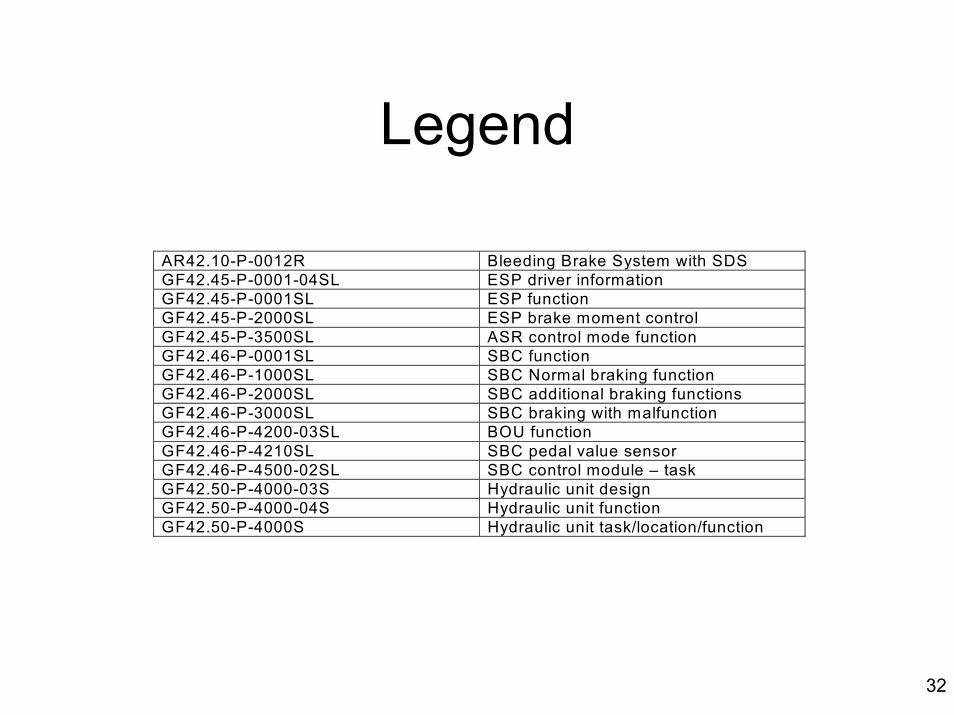
Legend
AR42.10-P-0012R Bleeding Brake System with SDSGF42.45-P-0001-04SL ESP driver informationGF42.45-P-0001SL ESP functionGF42.45-P-2000SL ESP brake moment controlGF42.45-P-3500SL ASR control mode functionGF42.46-P-0001SL SBC functionGF42.46-P-1000SL SBC Normal braking functionGF42.46-P-2000SL SBC additional braking functionsGF42.46-P-3000SL SBC braking with malfunctionGF42.46-P-4200-03SL BOU functionGF42.46-P-4210SL SBC pedal value sensorGF42.46-P-4500-02SL SBC control module – taskGF42.50-P-4000-03S Hydraulic unit designGF42.50-P-4000-04S Hydraulic unit functionGF42.50-P-4000S Hydraulic unit task/location/function


![GGIORNAMENTO 2013/1 CONTENUTO - Marola Attrezzature · 2017. 10. 12. · SBC (Sensotronic Brake Control) 3 . 6 [E 64] Cabrio . Exhaust gas treatment . Particulate filter 1.0 . 6 [E](https://img.dokumen.tips/doc/110x75/611d7dbb72bf0604af65bc00/ggiornamento-20131-contenuto-marola-2017-10-12-sbc-sensotronic-brake-control.jpg)