Embed Size (px)
Citation preview

Module 16
Earthquake Resistant Design of Structures
Version 2 CE IIT, Kharagpur

Lesson 39
Seismic Effects, Material Behaviour and
General Principles of Earthquake Resistant Design of Structures
Version 2 CE IIT, Kharagpur

Instructional Objectives:
At the end of this lesson, the student should be able to:
• state the direct and indirect seismic effects,
• explain the behaviour of plain concrete, steel and reinforced concrete with
high intensity repeated axial cyclic loads,
• define common terminologies needed for earthquake engineering,
• name different standards of BIS regarding the earthquake resistant design
of structures,
• state the assumptions of earthquake resistant design of structures,
• determine the horizontal seismic coefficient, design seismic base shear and
distribution of design force,
• state the steps of static elastic design of such structures,
• mention the objectives of earthquake resistant design of structures,
• explain the need for ductility and ductile detailing of reinforcement in the
earthquake resistant design of structures.
16.39.1 Introduction
Earthquakes, Tsunamis, Seiches, Landslides, Floods and Fires are natural calamities causing severe damage and sufferings to persons by collapsing the structures, cutting off transport systems, killing or trapping persons, animals etc. Such natural disasters are challenges to the progress of development. However, civil engineers as designers have a major role to play in minimising the damages by proper designing the structures or taking other useful decisions. Because of the vastness of the topic, “Disaster management and mitigation”, this module includes understanding the earthquakes, behaviour of the materials of construction and structures and the extent to which structural engineers make use of the knowledge in taking proper decisions in designing the structures made of reinforced concrete.
Version 2 CE IIT, Kharagpur

Earthquakes have many other effects besides vibrating the structures in response to ground shaking at its foundation. These other effects may even exceed that due to vibration. Unfortunately, the procedure of their estimation and the required steps for the design are considered outside the scope of structural engineering. Different seismic resistant design codes have provisions to take into account the vibration of structures. But, these codes do not have any provision to take care of other effects. However, structural engineers should be aware of the intensity of the hazards with a view to taking precautionary measures either in the design of structures, advising clients in selecting proper sites in such zones or making them aware of the importance of proper maintenance of the structures and other considerations the clients should follow up while using the designed structures. The different direct and indirect effects of earthquakes are mentioned in the following section. 16.39.2 Direct and Indirect Seismic Effects A. Direct effects. The following are the direct seismic effects: 1. Damage due to surface faulting
The damage due to surface faulting varies widely. It may totally demolish houses, rupture the foundations, tilt the foundation slabs and walls or may cause minor damage to the houses.
2. Damage due to liquefaction Liquefaction of soil may cause instability due to internal seismic waves
and thereby may significantly damage in form of settlement, tilting and rupture of the structures. The extent of damage depends on properties of soils of different layers, depth of the water table and the intensity, magnitude and duration of the earthquake. Accordingly, there may be either large settlement or differential settlement of the ground surface. Please refer to sec. 16.39.4(h) of this lesson for the definition of liquefaction as per IS Code.
It is always desirable to avoid construction in such areas than to design
the structures following codal provisions, which may be insufficient, though ensure effective design against vibration of structures due to shaking at the foundation level.
3. Damage due to ground shaking As the state of the art of this subject is still developing, integrated field
inspection of structures damaged by earthquakes and their analyses are useful in further adding/improving the expert knowledge in the seismic
Version 2 CE IIT, Kharagpur

resistant design and construction. Earlier inspections and analyses established the types of foundation, configurations of structures, materials of construction and design and detailing of construction. Such data are being continuously updated.
4. Damage due to sliding of superstructure on its foundation It is essential that the whole structure and the foundation should work as a
unit especially for the seismic resistant design and construction of structures. For this the superstructures should be anchored properly to the foundation.
5. Damage due to structural vibration The extent of the damage due to structural vibration depends on the
materials of construction. Wood, reinforced concrete and steel are widely used in civil engineering structures. It is well-known that inertia forces are developed as vibration response of a structure due to earthquake ground shaking. The intensity of such inertia forces is directly proportional to the product of mass and acceleration. Hence, reduction of mass is very effective to minimise the inertia forces. In this respect, timber has the maximum advantage as a potential construction material due to its low mass. Concrete, though a heavy material when reinforced with steel bars, has good strengths both in compression and in tension. Accordingly, reinforced concrete can be used effectively by providing proper amount of reinforcement and correct detailing of them as they play significant roles in the seismic resistant design of reinforced concrete structures. Steel has the additional advantages of ductility, strength and toughness per unit weight than concrete. The major problem of steel is the buckling. Behaviour of plain and reinforced concrete and steel with high intensity repeated axial cyclic loads is taken up in the next section.
B. Indirect effects Tsunamis, seiches, landslides, floods and fires are the indirect effects of
earthquakes. These may occur either alone or in combinations to add to the damages during an earthquake.
16.39.3 Behaviour of Concrete and Steel with High Intensity
Repeated Axial Cyclic Loads. Earthquakes cause ground motions in a random fashion in all directions having significant horizontal and vertical ground accelerations as function of time. Structures subjected to ground motions respond in a vibratory fashion. The maximum response acceleration during the elastic stage depends on the natural frequency of vibration of the structure and the magnitude of the damping. The
Version 2 CE IIT, Kharagpur

maximum inertia loads acting on a structure during an earthquake is determined by multiplying the mass by the acceleration. In order to understand the behaviour of reinforced concrete structure under such repeated cyclic loads, we first discuss the behaviour of plain concrete and reinforcing steel below. (a) Plain concrete Plain concrete has tensile strength less than twenty per cent of its compressive strength. The tensile strength of plain concrete is normally not obtained from the direct tension test because of difficulties in holding the specimens and the uncertainties of developing secondary stresses due to holding devices. Hence, this is measured indirectly either by split cylinder test or by bending test conducted on plain concrete prisms. Prism tests give the tensile strength of concrete in flexure, known as the modulus of rupture. Plain concrete specimens are not tested under repeated axial cyclic tensile loads.
However, earlier experiments on plain concrete cylinders with high intensity repeated axial compressive loads at slow rate of straining give the stress-strain curve as shown in Fig. 16.39.1. The stress-strain curve shows pronounced hysteresis effect and the envelope curve is almost identical to that of a single continuous load. Furthermore, such a curve obtained from the static test is also the same as that of the first cycle. Figure 16.39.1 shows that the slope of the stress-strain curve and the maximum attainable stress decrease with the number of cycles indicating the reduction of strength and stiffness of concrete due to the formation of cracks. With the increase of rate of loading, the compressive strength of concrete increases while the strain at the maximum stress decreases.
Version 2 CE IIT, Kharagpur

(b) Reinforcing steel
Figure 16.39.2 represents a typical stress-strain curve based on experiments with steel rods with repeated axial loads in tension and compression. Initially, the curve is similar to that obtained in static test in tension. On reversing the load after reaching the yield strain in tension, the unloading curve is seen to be curvilinear forming loops instead of the straight line as shown in Fig. 16.39.2, showing Bauschinger effect. The loop formed by one complete cycle is known as hysteresis loop, the area of which is the energy absorbed by the specimen in that cycle. Practically the same path is repeated in subsequent cycles. Thus, we find that the stress-strain curve for steel is cycle independent. The loop, therefore, continues for number of cycles till the specimen buckles or fails due to fatigue. It is also worth mentioning that the same hysteresis loops are obtained for specimens loaded first in compression, unloaded and reloaded in tension. However, the yield strength of steel is dependent on the rate of loading.
Version 2 CE IIT, Kharagpur

(c) Reinforced Concrete
Similar tests of loading and unloading in tension and compression on doubly-reinforced cantilever beam loaded with a point load P at the free end reveal the following:
(i) Formation of large cracks when the load P acting downward
causes post-elastic range of stress in tension steel (Fig. 16.39.3a).
Version 2 CE IIT, Kharagpur

(ii) Due to residual plastic strains in the steel, these cracks do not completely close on unloading but they remain open (Fig. 16.39.3b).
(iii) On loading the beam in a reverse direction (upward), as shown
in Fig. 16.39.3c, the resistance to rotation is decreased with respect to that during the first loading. This reduction is due to the presence of open cracks in the compression zone. As a result, the whole of compression is carried by compression steel. Thus, the flexural rigidity of the section is only that of steel.
(iv) At higher load (upward) when Bauschinger effect starts and
behaves inelastically, the flexural rigidity further reduces (Fig. 16.39.3d). The cracks in the compression zone may close depending on the magnitude of the load and the relative amounts of tension and compression steel. As a result, the stiffness of the member increases since concrete now can carry some compression load due to the closing of the cracks. However, if the cracks do not close and the member is unloaded, the cracks may be throughout the whole depth at critical sections. The width of these full-depth cracks depends on the amount of yielding and the effectiveness of the bond.
(v) If the member is again loaded downward, the member behaves
as a steel beam initially as the concrete is not in contact with the steel at the face of the crack.
Version 2 CE IIT, Kharagpur

Due to such reversal of loading, opening and closing of cracks in
the alternate tension and compression zones will gradually reduce the compressive strength of concrete either due to less or no contact because of slight relative lateral movement or presence of debris in the crack. This along with Bauchinger effect of steel gives the moment-curvature relation for the doubly-reinforced section as shown in Fig. 16.39.4. This diagram is far different from the idealised moment-curvature relation as shown in Fig. 16.39.5. The rounding and pinching of the loops of Fig. 16.39.4 clearly show smaller area than that of Fig. 16.39.5. Therefore, less energy will be dissipated per cycle in the actual case than the assumed idealised one. Accordingly, the response of frames to severe earthquake motions will be influenced by such effects.
Furthermore, the presence of high shear causing large shear
displacement will split the concrete longitudinally along the flexural steel bars leading to further loss of bond and stiffness.
Thus, the influential factors of load-displacement relationship of
reinforced concrete members during severe earthquake subjected to reversed inelastic deformations are summarised as:
Version 2 CE IIT, Kharagpur

1. Inelastic behaviour of steel reinforcement, 2. The extent of cracking of concrete,
3. Effectiveness of bond and anchorage, and
4. Presence of high shear.
Accordingly, realistic dynamic analyses shall be based on more accurate moment-curvature loops. The moment-curvature relationships, shown in Figs. 16.39.4 and 16.39.5, reveal that the deformation changes from cycle to cycle after the yielding starts.
16.39.4 Terminology for Earthquake Engineering (a) Design Basis Earthquake (DBE) It is an earthquake which can reasonably be expected to occur at least
once during the design life of the structure, as defined in cl.3.6 of IS 1893 (Part 1): 2002.
(b) Epicentre Epicentre is the geographical point on the surface of earth vertically above
the focus of the earthquake (cl.3.10 of IS 1893 (Part 1): 2002). (c) Focus Focus is the source of the elastic waves of the originating earthquake
inside the earth which cause shaking of ground (cl. 3.13 of IS 1893 (Part 1): 2002).
(d) Intensity of earthquake The intensity of an earthquake indicates the strength of shaking during the
earthquake and is expressed by a number according to the modified Mercalli Scale or M.S.K Scale of seismic intensities (cl. 3.15 of IS 1893 (Part 1): 2002).
(e) Magnitude of earthquake (Richter’s Magnitude) The magnitude of an earthquake is expressed by a number, which is a
measure of the energy released in an earthquake. The magnitude of an earthquake is defined as logarithm to the base 10 of the maximum trace amplitude, expressed in micron, which the standard short-period torsion
Version 2 CE IIT, Kharagpur

seismometer (with a period of 0.8 second, magnification of 2800 and damping nearly critical) would register due to the earthquake at an epicentral distance of 100 km (cl. 3.18 of IS 1893 (Part 1): 2002).
(f) Critical damping Critical damping is the damping beyond which the free vibration motion
will not be oscillatory (cl. 3.3 of IS 1893 (Part 1): 2002). (g) Maximum Considered Earthquake (MCE) Maximum Considered Earthquake is the most severe earthquake whose
effects are considered by IS 1893 (Part 1): 2002, as given in cl. 3.19 of this standard.
(h) Liquefaction Liquefaction is a state in saturated cohesionless soil wherein the effective
shear strength is reduced to negligible value for all engineering purposes due to pore pressure caused by vibrations during an earthquake when they approach the total confining pressure. In this condition the soil tends to behave like a fluid mass (cl. 3.16 of IS 1893 (Part 1): 2002).
16.39.5 Bureau of Indian Standards for Earthquake Design In our country, several major earthquakes have occurred in the Himalayan-Nagalushai region, Indo-Gangetic Plain, Western India, Kutch and Kathiawar regions. Taking into account seismic data from studies of these Indian earthquakes, Bureau of Indian Standard first published IS 1893 “Recommendations for earthquake resistant design of structures” in 1962 and revised in 1966. Considering the local seismology, accepted level of seismic risk, building topologies and materials and methods used in construction, presently the Bureau of Indian Standards has the following seismic codes:
1. IS 1893 (Part 1), 2002; Indian Standard Criteria for Earthquake Resistant Design of Structures (5th Revision),
2. IS 1893 has other four parts: (a) Part 2 for liquid retaining tanks–
elevated and ground supported, (b) Part 3 for bridges and retaining walls, (c) Part 4 for industrial structures including stack like structures and (d) Part 5 for dams and embankments. However, they are yet to be finalised. Hence, provisions of Part 1 will be read along with relevant clauses of IS 1893: 1984 for structures other than buildings.
Version 2 CE IIT, Kharagpur

3. IS 4326: 1993, Indian Standard Code of Practice for Earthquake Resistant Design and Construction of Buildings, (2nd Revision),
4. IS 13827: 1993, Indian Standard Guidelines for Improving Earthquake
Resistance of Earthen Buildings,
5. IS 13828: 1993, Indian Standard Guidelines for Improving Earthquake Resistance of Low Strength Masonary Buildings,
6. IS 13920: 1993, Indian Standard Code of Practice for Ductile Detailing
of Reinforced Concrete Structures Subjected to Seismic Forces, and
7. IS 13935: 1993, Indian Standard Guidelines for Repair and Seismic Strengthening of Buildings.
The regulations of these standards will not result in structures having no damage during earthquake of all magnitudes. However, the regulations shall ensure that, as far as possible, structures will be able to respond without structural damage to shocks of moderate intensities and without total collapse to shocks of heavy intensities.
16.39.6 General Principles of Earthquake Resistant
Design of Structures
a) Ground motion
The characteristic parameters like intensity, duration etc. of seismic ground vibrations depend upon the magnitude of the earthquake, its depth of focus, distance from the epicentre, properties of soil or medium through which the seismic waves travel and the soil strata where the structure stands. The random earthquake motions can be resolved in any three mutually perpendicular directions. The horizontal direction is normally the prominent direction. Vertical acceleration is considered in large-span structures.
The response of a structure to ground vibrations depends on the nature of
foundation soil, form, material, size and mode of construction of structures and the duration and characteristics of ground motion.
(b) Assumptions
The following are the assumptions in the earthquake resistant design of structures:
Version 2 CE IIT, Kharagpur
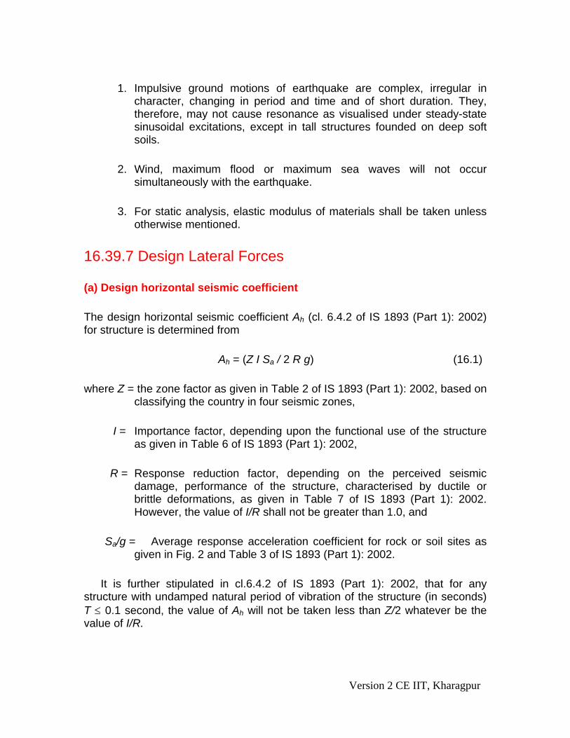
1. Impulsive ground motions of earthquake are complex, irregular in
character, changing in period and time and of short duration. They, therefore, may not cause resonance as visualised under steady-state sinusoidal excitations, except in tall structures founded on deep soft soils.
2. Wind, maximum flood or maximum sea waves will not occur
simultaneously with the earthquake.
3. For static analysis, elastic modulus of materials shall be taken unless otherwise mentioned.
16.39.7 Design Lateral Forces (a) Design horizontal seismic coefficient The design horizontal seismic coefficient Ah (cl. 6.4.2 of IS 1893 (Part 1): 2002) for structure is determined from Ah = (Z I Sa / 2 R g) (16.1) where Z = the zone factor as given in Table 2 of IS 1893 (Part 1): 2002, based on
classifying the country in four seismic zones, I = Importance factor, depending upon the functional use of the structure
as given in Table 6 of IS 1893 (Part 1): 2002, R = Response reduction factor, depending on the perceived seismic
damage, performance of the structure, characterised by ductile or brittle deformations, as given in Table 7 of IS 1893 (Part 1): 2002. However, the value of I/R shall not be greater than 1.0, and
Sa/g = Average response acceleration coefficient for rock or soil sites as
given in Fig. 2 and Table 3 of IS 1893 (Part 1): 2002. It is further stipulated in cl.6.4.2 of IS 1893 (Part 1): 2002, that for any structure with undamped natural period of vibration of the structure (in seconds) T ≤ 0.1 second, the value of Ah will not be taken less than Z/2 whatever be the value of I/R.
Version 2 CE IIT, Kharagpur

(b) Design seismic base shear The total design lateral force or design seismic base shear VB along any
principal direction (cl.7.5.3 of IS 1893 (Part 1): 2002) shall be determined from the following equation:
VB = Ah W (16.2) where Ah is as given in Eq. 16.1, and W is the seismic weight of the building
as given in cl. 7.4.2 of IS 1893 (Part 1): 2002. (c) Distribution of design force The design base shear VB of Eq. 16.2 shall be distributed along the height of
the building as per the following equation (cl.7.7 of IS 1893 (Part 1): 2002): B
2j
(16.3) 2
1
n
i B i i ij
Q V (W h ) / W h=
= ∑where Qi = Design lateral force at floor i, Wi = Seismic weight of floor i, hi = Height of floor i measured from base, and n = Number of storeys in the building at which the masses are located 16.39.8 Static Elastic Design The various steps, based on the elastic design are:
1. Dead load and imposed loads are considered as per cl.6.3 of IS 1893 (Part 1): 2002.
2. The horizontal loads are determined as explained in sec. 16.39.7.
3. Bending moments and shear forces are determined on columns and floor
beams in a manner similar to that of frames subjected to wind loads.
4. All parts must be efficiently bonded together so that the structure acts as a unit.
Version 2 CE IIT, Kharagpur

5. Panel walls, finishes and ornaments should be permanently attached to the frame to ensure that they do not collapse independently in the event of a shock.
6. Separate footings of columns shall be connected by ties to resist the
compressive thrust or tensile pull of magnitude 1/10th of the load on the footing.
Structures designed on this simple elastic principle may even survive when subjected to severe earthquake due to the following:
a) Yielding at critical sections increases the period of vibration and helps to
absorb greater amounts of input energy. b) Assistance of non-structural partitions and the dissipated energy are
helpful as they crack.
c) Yielding of foundations helps to reduce the predicted response. 16.39.9 Dynamic Analysis Though static elastic analysis is considered sufficient for smaller building, dynamic analyses shall be performed to determine the seismic force and its distribution to different levels for regular and irregular buildings, as defined in cl. 7.1 of IS 1893 (Part 1): 2002, following the recommendations of cl. 7.8 of the same IS Code.
(a) Regular buildings – Those greater than 40 m in height in Zones IV and V and those greater than 90 m in height in Zones II and III,
(b) Irregular buildings – All framed buildings higher than 12 m in Zones IV and
V and those higher than 40 m in Zones II and III.
Though not mandatory, the code also recommends dynamic analysis for buildings lesser than 40 m for irregular building in Zones II and III (see Note below cl.7.8.1 of IS 1893 (Part 1): 2002).
The dynamic analysis may be carried out either by Time History Method or by Response Spectrum Method. More about the dynamic analysis is beyond the scope of this module.
Version 2 CE IIT, Kharagpur
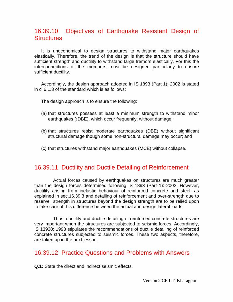
16.39.10 Objectives of Earthquake Resistant Design of Structures It is uneconomical to design structures to withstand major earthquakes elastically. Therefore, the trend of the design is that the structure should have sufficient strength and ductility to withstand large tremors elastically. For this the interconnections of the members must be designed particularly to ensure sufficient ductility. Accordingly, the design approach adopted in IS 1893 (Part 1): 2002 is stated in cl 6.1.3 of the standard which is as follows: The design approach is to ensure the following:
(a) that structures possess at least a minimum strength to withstand minor earthquakes (⟨DBE), which occur frequently, without damage;
(b) that structures resist moderate earthquakes (DBE) without significant
structural damage though some non-structural damage may occur; and
(c) that structures withstand major earthquakes (MCE) without collapse.
16.39.11 Ductility and Ductile Detailing of Reinforcement Actual forces caused by earthquakes on structures are much greater than the design forces determined following IS 1893 (Part 1): 2002. However, ductility arising from inelastic behaviour of reinforced concrete and steel, as explained in sec.16.39.3 and detailing of reinforcement and over-strength due to reserve strength in structures beyond the design strength are to be relied upon to take care of this difference between the actual and design lateral loads. Thus, ductility and ductile detailing of reinforced concrete structures are very important when the structures are subjected to seismic forces. Accordingly, IS 13920: 1993 stipulates the recommendations of ductile detailing of reinforced concrete structures subjected to seismic forces. These two aspects, therefore, are taken up in the next lesson. 16.39.12 Practice Questions and Problems with Answers Q.1: State the direct and indirect seismic effects.
Version 2 CE IIT, Kharagpur

A.1: Section 16.39.2 is the complete answer Q.2: Explain the behaviour of plain concrete with high intensify repeated axial
cyclic loads. A.2: Part (a) of sec. 16.39.3 Q.3: Explain the behaviour of steel with high intensity repeated axial cyclic loads. A.3: Part (b) of sec. 16.39.3 Q.4: Explain the behaviour of reinforced concrete with high intensity repeated
axial cyclic loads. A.4: Part (c) of sec. 16.39.3 Q.5: Define the following terminologies as per IS 1893 (Part 1): 2002: (a) Design
Basis Earthquake (DBE), (b) Epicentre, (c) Focus, (d) Intensify of earthquake, (e) Magnitude of earthquake, (f) critical damping, (g) Maximum Considered Earthquake and (h) Liquefaction.
A.5: Section 16.39.4 is the complete answer. Q.6: Name the different BIS Standards for earthquake design. A.6: Section 16.39.5 is the complete answer. Q.7: Write the expression for determining (a) Horizontal seismic coefficient, (b)
Design seismic base shear and (c) Distribution of design force. A.7: Section 16.39.7 is the complete answer. Q.8: Write the steps of performing static elastic design of earthquake resistant
structures. A.8: Section 16.39.8 is the complete answer.
Version 2 CE IIT, Kharagpur

Q.9: When should we have to perform dynamic analysis? A.9: Section 16.39.9 is the complete answer. Q.10: State the objectives of earthquake resistant design of structures. A.10: Section 16.39.10 is the complete answer. Q.11: Explain the need of ductility and ductile detailing of reinforced concrete
structures subjected to seismic forces. A.11: Section 16.39.11 is the complete answer.
16.39.13 References
1. Reinforced Concrete Limit State Design, 6th Edition, by Ashok K. Jain, Nem Chand & Bros, Roorkee, 2002.
2. Limit State Design of Reinforced Concrete, 2nd Edition, by P.C. Varghese, Prentice-Hall of India Pvt. Ltd., New Delhi, 2002.
3. Advanced Reinforced Concrete Design, by P.C. Varghese, Prentice-Hall of India Pvt. Ltd., New Delhi, 2001.
4. Reinforced Concrete Design, 2nd Edition, by S. Unnikrishna Pillai and Devdas Menon, Tata McGraw-Hill Publishing Company Limited, New Delhi, 2003.
5. Limit State Design of Reinforced Concrete Structures, by P. Dayaratnam, Oxford & I.B.H. Publishing Company Pvt. Ltd., New Delhi, 2004.
6. Reinforced Concrete Design, 1st Revised Edition, by S.N. Sinha, Tata McGraw-Hill Publishing Company. New Delhi, 1990.
7. Reinforced Concrete, 6th Edition, by S.K. Mallick and A.P. Gupta, Oxford & IBH Publishing Co. Pvt. Ltd. New Delhi, 1996.
8. Behaviour, Analysis & Design of Reinforced Concrete Structural Elements, by I.C.Syal and R.K.Ummat, A.H.Wheeler & Co. Ltd., Allahabad, 1989.
9. Reinforced Concrete Structures, 3rd Edition, by I.C.Syal and A.K.Goel, A.H.Wheeler & Co. Ltd., Allahabad, 1992.
10. Textbook of R.C.C, by G.S.Birdie and J.S.Birdie, Wiley Eastern Limited, New Delhi, 1993.
11. Design of Concrete Structures, 13th Edition, by Arthur H. Nilson, David Darwin and Charles W. Dolan, Tata McGraw-Hill Publishing Company Limited, New Delhi, 2004.
12. Concrete Technology, by A.M.Neville and J.J.Brooks, ELBS with Longman, 1994.
Version 2 CE IIT, Kharagpur

13. Properties of Concrete, 4th Edition, 1st Indian reprint, by A.M.Neville, Longman, 2000.
14. Reinforced Concrete Designer’s Handbook, 10th Edition, by C.E.Reynolds and J.C. Steedman, E & FN SPON, London, 1997.
15. Indian Standard Plain and Reinforced Concrete – Code of Practice (4th Revision), IS 456: 2000, BIS, New Delhi.
16. Design Aids for Reinforced Concrete to IS: 456 – 1978, BIS, New Delhi. 17. Structural Engineering Slide Library, W.G.Godden, Editor; Set J:
Earthquake Engineering V.V.Bertero, National Information Service for Earthquake Engineering, University of California, Berkeley, USA. ( http://nisee.berkeley.edu/bertero/html/damage_due_to_ground_failure.html )
16.39.14 Test 39 with Solutions Maximum Marks = 50 Maximum Time = 30
minutes Answer all questions. TQ.1: State the direct and indirect seismic effects.
(10 Marks) A.TQ.1: Section 16.39.2 is the complete answer TQ.2: Explain the behaviour of reinforced concrete with high intensity repeated
axial cyclic loads. (10 Marks)
A.TQ.2: Part (c) of sec. 16.39.3 TQ.3: Name the different BIS Standards for earthquake design.
(15 Marks) A.TQ.3: Section 16.39.5 is the complete answer. TQ.4: Write the steps of performing static elastic design of earthquake resistant
structures. (10 Marks)
A.TQ.4: Section 16.39.8 is the complete answer. TQ.5: State the objectives of earthquake resistant design of structures.
(5 Marks)
Version 2 CE IIT, Kharagpur

A.TQ.5: Section 16.39.10 is the complete answer. 16.39.15 Summary of this Lesson This lesson explains the direct and indirect effects of earthquakes. Behaviour of plain concrete, steel bars and reinforced concrete are discussed when subjected to high intensity repeated axial loads. Some common terminologies are defined as given in IS 1893 (Part 1): 2002. Different BIS standards pertaining to earthquake design are given. General principles and assumptions are given in this lesson. Determinations of horizontal seismic coefficient, design seismic base shear and distribution of design force are explained. Steps of the static elastic design are given mentioning the particular situations when dynamics analysis should be done. The objectives of earthquake resistant design of structures are explained. The need for ductility and ductile detailing of reinforcement is explained in this lesson.
Version 2 CE IIT, Kharagpur