Embed Size (px)
Citation preview

100 IEEE TRANSACTIONS ON NETWORKING, VOL. XX, NO. Y, MONTH 2004
Dynamic Core Provisioning for QuantitativeDifferentiated Services
Raymond R.-F. Liao,Member, IEEE,and Andrew T. Campbell,Member, IEEE
Abstract— Efficient network provisioning mechanisms thatsupport service differentiation and automatic capacity dimen-sioning are essential to the realization of the DifferentiatedServices (DiffServ) Internet. Building on our prior work onedge provisioning, we propose a set of efficient dynamic nodeand core provisioning algorithms for interior nodes and corenetworks, respectively. The node provisioning algorithm preventstransient violations of service level agreements by predicting theonset of service level violations based on a multi-class virtualqueue measurement technique, and by automatically adjustingthe service weights of weighted fair queueing schedulers at corerouters. Persistent service level violations are reported to thecore provisioning algorithm, which dimensions traffic aggregatesat the network ingress edge. The core provisioning algorithm isdesigned to address the difficult problem of provisioning DiffServtraffic aggregates (i.e., rate-control can only be exerted at theroot of any traffic distribution tree) by taking into accountfairness issues not only across different traffic aggregates butalso within the same aggregate whose packets take differentroutes through a core IP network. We demonstrate throughanalysis and simulation that the proposed dynamic provisioningmodel is superior to static provisioning for DiffServ in providingquantitative delay bounds with differentiated loss across per-aggregate service classes under persistent congestion and devicefailure conditions when observed in core networks.
Index Terms— Virtual Queue, Point-to-Multipoint Congestion,Service Differentiation, Capacity Dimension.
I. I NTRODUCTION
EFFICIENT capacity provisioning for the DifferentiatedServices (DiffServ) Internet [1] appears more challenging
than in circuit-based networks such as the AsynchronousTransfer Mode (ATM) networks for two reasons. First, thereis a lack of detailed control information (e.g., per-flow states)and support mechanisms (e.g., per-flow queueing) in thenetwork. Second, there is a need to provide increased levelsof service differentiation over a single global IP infrastruc-ture. In traditional telecommunication networks, where trafficcharacteristics are well understood and well controlled, long-term capacity planning can be effectively applied. We argue,however, that in a DiffServ Internet more dynamic forms ofcontrol will be required to compensate for coarser-grainedstate information and the lack of network controllability, ifservice differentiation is to be realistically delivered.
There exists a trade-off intrinsic to the DiffServ servicemodel (i.e., qualitative vs. quantitative control). DiffServ aims
Raymond Liao is with Siemens TTB, 1995 University Ave., Suite 375,Berkeley, CA 94704, USA. This research was conducted while he was withthe Dept. of Electrical Engineering, Columbia University. Andrew T. Campbellis with the Dept. of Electrical Engineering, Columbia University, New York,NY10027, USA. E-mail:{liao, campbell}@comet.columbia.edu
to simplify the resource management problem thereby gainingarchitectural scalability through provisioning the network ona per-aggregate basis, which results in some level of servicedifferentiation between service classes that isqualitative innature. Although under normal conditions, the combination ofDiffServ router mechanisms and edge regulation of servicelevel agreements (SLA) could plausibly be sufficient for ser-vice differentiation in an over-provisioned Internet backbone,network practitioners need to usequantitative provisioningrules to automatically re-dimension a network that experiencespersistent congestion or device failure while attempting tomaintain service differentiation [2], [3]. Therefore, a keychallenge for the emerging DiffServ Internet is to developsolutions that can deliver suitable network control granularitywith scalable and efficient network state management.
In this paper, we propose an approach to provisioningquantitative differential services within a service provider’snetwork (i.e., the intra-domain aspect of the provisioningproblem). Our SLA provides quantitative per-class delay guar-antees with differentiated loss bounds across core IP networks.We introduce a distributednode provisioning algorithmthatworks with class-based weighted fair (WFQ) schedulers andqueue management schemes. This algorithm prevents transientservice level violations by adjusting the service weights fordifferent classes after detecting the onset of SLA violations.The algorithm uses a simple but effective approach (i.e.,the virtual queue method proposed in [4], [5]) to predictpersistent SLA violations from measurement data and sendsalarm signals to our networkcore provisioning algorithm. Ourstress test results for both bursty On-Off and TCP applicationtraffic show that the node provisioning algorithm alone canguarantee the delay and loss bounds when there is a lowfrequency (below 10%) of alarms raised. When there is aSLA violation, the algorithm will first meet the delay boundsacrificing the loss bound. For adaptive applications suchas TCP which respond to packet losses, this approach hasshown to be effective even without the involvement of coreprovisioning algorithms.
One challenge facing DiffServ network provisioning is therate control of traffic aggregates that comprise flows exiting thecore network at different network egress points. A rate controlfunction includes traffic policing (i.e., packet dropping) and/ortraffic shaping. This problem occurs when rate control can onlybe exerted on a per traffic aggregate basis, (i.e., at the rootof a traffic aggregate’s point-to-multipoint distribution tree).Under such conditions, any rate reduction of an aggregatewould penalizes traffic flowing along branches of the point-to-multipoint distribution tree that are not congested. We

LIAO AND CAMPBELL: DYNAMIC CORE PROVISIONING FOR QUANTITATIVE DIFFERENTIATED SERVICES 101
call such a penaltybranch-penalty. Branch-penalty exists inDiffServ networks because rate control is performed at theingress edge of the network instead of in the core of thenetwork. Existing flow control algorithms have focused onfairness across different traffic aggregates while overlookingthe effect of branch-penalty, which can lead to severe band-width reduction on traffic aggregates whose portion of trafficflowing through a congested link is small, and resulting inunnecessary under-utilization of network links that are notcongested. Our approach, in contrast, comprises a suite ofpolicies that minimize branch-penalty, deliver fairness withequal reduction across traffic aggregates, or extend the max-min fairness for point-to-multipoint traffic aggregates.
In summary, this paper makes two contributions. First,our node provisioning algorithm prevents transient servicelevel violations by dynamically adjusting the service weightsof a weighted fair queueing scheduler. The algorithm ismeasurement-based and effectively uses the multi-class virtualqueue technique to predict the onset of SLA violations. Sec-ond, our core provisioning algorithm is designed to address theunique difficulty of provisioning DiffServ traffic aggregates.We proposed an algorithm that balances the trade-off betweenfairness and minimizing the branch-penalty. Collectively, thesealgorithms contribute toward a more quantitative differentiatedservice Internet, supporting per-class delay guarantees withdifferentiated loss bounds across core IP networks.
This paper is structured as follows. In Section II, wediscuss related work. In Section III, we introduce a dynamicprovisioning architecture and service model. Following this,in Section IV, we present our dynamic node provisioningmechanism, which monitors buffer occupancy, self-adjustsscheduler service weights and packet dropping thresholdsat core routers. In Section V, we describe our core provi-sioning algorithm, which dimensions bandwidth at ingresstraffic conditioners located at edge routers taking into accountthe fairness issue of point-to-multipoint traffic aggregatesand SLAs. In Section VI, we discuss our simulation resultsdemonstrating that the proposed algorithms are capable ofsupporting the dynamic provisioning of SLAs with guaranteeddelay, differential loss and bandwidth prioritization across per-aggregate service classes. We also verify the effect of rateallocation policies on traffic aggregates. Finally, in Section VII,we present some concluding remarks.
II. RELATED WORK
Dynamic network provisioning algorithms are complemen-tary to scheduling and admission control algorithms. Theprovisioning algorithms introduced in this paper operate ona medium time scale, as illustrated in Fig. 1. In contrast,packet scheduling and flow control operate on fast timescales (i.e., sub-second time scales); admission control anddynamic provisioning operate on medium time scales in therange of seconds to minutes; and traffic engineering, includingrerouting and capacity planning, operate on slower time scaleson the order of hours to months. Significant progress hasbeen made in the area of scheduling and flow control, (e.g.,dynamic packet state and its derivatives [6], [7]). In the area of
traffic engineering, solutions for circuit-based networks havebeen widely investigated in literature (e.g., [8], [9]). There hasbeen recent progress on developing measurement techniquesfor IP networks [10]–[12]. In contrast, for the medium timescale mechanisms, most research effort has been focused onadmission control issues including edge [13] and end hostbased admission control [14]. However, these algorithms donot provide fast mechanisms that are capable of reacting tosudden traffic pattern changes. Our dynamic provisioning algo-rithms are capable of quickly restoring service differentiationunder severely congested and device failure conditions.
Delivering quantitative service differentiation for the Diff-Serv service model in a scalable manner has attracted a lot ofattentions recently. A number of researchers have proposedeffective scheduling algorithms. Stoica et. al. propose theDynamic Packet State [6] to maintain per-flow rate informationin packet headers leading to fine-grained per-flow packet-dropping that is locally fair (i.e., at a local switch). However,this scheme is not max-min fair due to the fact that anypacket drops inside the core network wastes upstream linkbandwidth that otherwise could be utilized. In [7], Stoica andZhang extend the solution of [6] to support per-flow delayguarantees in a DiffServ network. Our work operates on topof per-class schedulers with emphasis on bandwidth allocationand the maintenance of service differentiation and network-wide fairness properties. The proportional delay differentiationscheme [15] defines a new qualitative “relative differentiationservice” as oppose to quantifying “absolute differentiatedservices”. The node provisioning algorithm presented in thispaper also adopts a self-adaptive mechanism to adjust ser-vice weights at core routers. However, our service modeldiffers from [15] by providing delay guarantees across a corenetwork while maintaining relative loss differentiation. Thework discussed in [16] has similar objectives to our nodeprovisioning algorithm. However, it is motivated by a morecomprehensive set of objectives in comparison to our workbecause it attempts to support optimization objectives thatinclude multiple constraints for both relative and absolute lossand delay differentiation.
The idea of using virtual queues in scheduler design is a wellaccepted technique. For example, in [17] a duplicate queue isconstructed to support two “Alternative Best-Effort” services(viz. low delay vs. high throughput). In our work, we usevirtual queues to predict the onset of SLA violations. The ideawas originally proposed in [4], [5] as a good traffic predictiontechnique for traffic with complex characteristics, such as, selfsimilarity, because its stochastic properties share the samedominant time scale with the original queue. Our algorithmextends this work by dynamically adjusting the virtual queuescaling parameter with respect to queueing conditions.
Our approach to dynamic provisioning is complementaryto the work on edge/end-host based admission control [13],[14], with admission control at the edge of core networksand provisioning algorithms operating inside core networks.An alternative approach that solely uses admission control fora DiffServ network can support stricter QoS guarantee butalso lead to more complexity in the QoS control plane. Forexample, in [18] a complex bandwidth broker algorithm is

102 IEEE TRANSACTIONS ON NETWORKING, VOL. XX, NO. Y, MONTH 2004
admission controldynamic provisioning
seconds to hours
rerouting−basedtraffic engineering
hours to days
capacity planningpeering negotiation
weeks to months
flowcontrol
100 of msec
schedulingpacket
sub−msec
Fig. 1. Network Provisioning Time Scale
presented to maintain the control states of core routers andperform admission control for the whole network. In contrast,our provisioning algorithm uses a distributed node algorithmto detect and signal the need for bandwidth re-allocation. Thecentralized core algorithm only maintains the network loadmatrix and coordinates the allocation algorithm for fairnesspurposes.
One could argue that this problem could be resolved bybreaking down a customer’s traffic aggregates into per ingress-egress pairs and provisioning these pairs in a similar mannerto circuit-based Multi-Protocol Label Switching (MPLS) [19]tunnels. However, such an approach would only work ifthe tunnel topology of virtual private networks (VPN) isa mesh. It would not work if a more scaleable hub-and-spoke topology is used for deploying VPNs because hub-and-spoke topologies lead to point-to-multipoint distributiontrees. In addition, this approach would not work when thenumber of tunnels exceeds the number of shaper queuessupported in edge routers. Our approach does not excludesupport for MPLS tunnels, but benefits from any availabilityof MPLS tunnels because MPLS per-tunnel traffic accountingstatistics will improve the measurement accuracy of our trafficmatrix, as discussed in Section V-A. As a result, our approachimproves the scalability of per-MPLS-tunnel traffic shaping bysupporting traffic regulation for MPLS aggregates.
Currently network service providers use rerouting basedtraffic engineering approaches to cope with network trafficdynamics on slow time-scales. In the inter-domain case whereone provider has no direct control of its peering networks, ab-sence of direct control leads to the use of intra-domain routingpolicy as the only viable technique, with potential solutionsranging from optimal planning of routes for circuits/virtualpaths [20], to traffic measurement based adjustment on OSPFweights and BGP route policies [10]. In the intra-domain casewhere direct control is possible, dynamic provisioning canoffer faster response to service degradation.
Our provisioning method bears similarity to the work onedge-to-edge flow control [21] but differs in that we providea solution for point-to-multipoint traffic aggregates unique toa DiffServ network rather than the point-to-point approachdiscussed in [21]. In addition, our emphasis is on the deliveryof multiple levels of service differentiation.
III. D YNAMIC NETWORK PROVISIONING MODEL
A. Architecture
We assume a DiffServ framework where edge traffic condi-tioners perform traffic policing/shaping. Nodes within the corenetwork use a class-based weighted fair (WFQ) scheduler and
various queue management schemes for dropping packets thatoverflow queue thresholds.
The dynamic capacity provisioning architecture illustratedin Fig. 2 comprises dynamic core and node provisioningmodules for bandwidth brokers and core routers, respectively,as well as the edge provisioning modules that are located ataccess and peering routers. The edge provisioning module [22]performs ingress link sharing at access routers, and egresscapacity dimensioning at peering routers.
B. Control Messaging
Dynamic core provisioning sets appropriate ingress trafficconditioners located at access routers by utilizing acore trafficload matrix to apply rate-reduction (via aRegulateIngressDown signal) at ingress conditioners, as shown in Fig. 2.Ingress conditioners are periodically invoked (via theReg-ulate Ingress Upsignal) over longer restoration time scalesto increase bandwidth allocation restoring the max-min band-width allocation when resources become available. The coretraffic load matrix maintains network state information. Thematrix is periodically updated (viaLinkStateUpdate signal)with the measured per-class link load. In addition, when thereis a significant change in the rate allocation at egress accessrouters, a core bandwidth broker uses aSinkTreeUpdatesignalto notify egress dimensioning modules at peering routers whenrenegotiating bandwidth with peering networks, as shown inFig. 2. We use the term “sink-tree” to refer to the topologicalrelationship between a single egress link (representing the rootof a sink-tree) and two or more ingress links (representing theleaves of a sink-tree) that contribute traffic to the egress point.
Dynamic core provisioning is triggered bydynamic nodeprovisioning (via a CongestionAlarm signal as illustrated inFig. 2) when a node persistently experiences congestion for aparticular service class. This is typically the result of somelocal threshold being violated. Dynamic node provisioningadjusts service weights of per-class weighted schedulers andqueue dropping thresholds at local core routers with the goal ofmaintaining delay bounds and differential loss, and bandwidthpriority assurances.
C. Service Model
The proportional delay differentiation service proposed in[15] defines the relative service differentiation of a single nodeand not a path through a core network. In contrast, our workproduces service assurances that are quantitative in terms ofdelay bound and loss differentiation, and support bandwidthallocation priorities across service classes within a DiffServcore network.

LIAO AND CAMPBELL: DYNAMIC CORE PROVISIONING FOR QUANTITATIVE DIFFERENTIATED SERVICES 103
RouterAccess
RouterAccess
RouterPeering
Provisioning
Dynamic Node
Provisioning
Dynamic Node
PeeringRouter
Bandwidth
Provisioning
Brokers
Dynamic Core Core TrafficLoad Matrix
SinkTree_UpdateRegulate_Ingress
Up/Down
Congestion_Alarm LinkState_Update
Core Routers
Ingress LogicalSource Tree Physical Link
Egress LogicalSink Tree
Fig. 2. Dynamic Capacity Provisioning Model
Our SLA comprises:
• a delay guarantee: where any packet delivered throughthe core network (not including the shaping delay of edgetraffic conditioners) has a delay bound ofDi for networkservice classi;
• a differentiated loss assurance: where network serviceclasses are loss differentiated, that is, for traffic routedthrough the same path in a core network, the long-termaverage loss rate experienced by classi is no larger thanP ∗loss,i. The thresholds{P ∗loss,i} are differentiated, i.e.,P ∗loss,(i−1) < P ∗loss,i;
• a delay bound precedence over loss bound: when boththe delay and loss bounds can not be maintained for classi, the loss bound will be revoked first before the delaybound;
• a bandwidth allocation priority: where the traffic of classj never affects the bandwidth/buffer allocation of classi, i < j, that is, the delay and loss bounds of classi willbe revoked only after there is no bandwidth available(excluding the minimum bandwidth for each class) inclassesj, j > i ; and
• a bandwidth utility function: which provides an applica-tion programming interface (API) for edge service differ-entiation. The utility function serves as a user-approvedper-class QoS degradation trajectory used by networkprovisioning algorithms under network congestion orfailure conditions.
We design the service model such that maintaining aquantitative delay bound takes precedence over maintainingthe packet loss bound. This precedence helps to simplify thecomplexity of jointly maintaining both loss and delay boundsat the same time. In addition, such a service is suitable forTCP applications that need packet loss as an indicator for flowcontrol while guaranteed delay performance can support real-time applications. The precedence to delay bound does notmean that the loss bound will be ignored. For a service classwith higher bandwidth allocation priority, its loss bound willbe maintained at the cost of violating lower priority classes’
loss and delay bounds.In addition, the CongestionAlarm signal from the node
provisioning algorithm will give an early warning to the coreprovisioning algorithm, which can work with the admissioncontrol algorithm and edge-based traffic regulation algorithmto remove congestion inside the core network. One benefit ofour dynamic provisioning algorithm is its ability to maintainservice differentiation under unavoidable prediction errorsmade by the admission control algorithm.
The granularity of per-node delay boundsDi is limitedby the nature of slow time scale aggregate provisioning. Thechoice ofDi has to take into consideration the sum of a singlepacket transmission time at the link rate and a single packetservice time through various fair queue schedulers [23]. Thisis in addition to the queueing delays due to traffic aggregatesinside the core network.
The choice of the loss thresholdP ∗loss,i in an SLA also needsto consider the application behavior. For example, a serviceclass intended for data applications should not specify a lossthreshold that can impact steady-state TCP behavior. Studies[24] indicate that the packet drop thresholdP ∗loss,i shouldnot exceed0.01 for data applications to avoid the penalty ofretransmission timeouts.
We define a service model for the core network that in-cludes a number of algorithms. A node provisioning algorithmenforces delay guarantees by dropping packets and adjustingservice weights accordingly. A core provisioning algorithmmaintains the dropping-rate differentiation by dimensioningthe network ingress bandwidth. Edge provisioning modulesperform rate regulation based on utility functions. Even thoughthese algorithms are not the only solution to supporting theproposed SLA, their design is tailored toward delivering quan-titative differentiation in the SLA with minimum complexity.
Note that utility function based edge dimensioning has beeninvestigated in our prior work [22]. In the remaining part ofthis paper we focus on core network provisioning algorithmsthat are complementary components to the edge algorithms ofour dynamic provisioning architecture shown in Fig. 2.

104 IEEE TRANSACTIONS ON NETWORKING, VOL. XX, NO. Y, MONTH 2004
IV. DYNAMIC NODE PROVISIONING
The design of the node provisioning algorithm follows thetypical logic of measurement based closed-loop control. Thealgorithm is responsible for two tasks: (i) to predict SLAviolations from traffic measurements; and (ii) to respond topotential violations with local reconfiguration. If violations aresevere and persistent, then reports are sent to the core provi-sioning modules to regulate ingress conditioners, as shown inFig. 2.
The detection of SLA violation is triggered by the virtualqueue method proposed in [4], [5]. A virtual queue has exactlythe same incoming traffic as its corresponding real queue butwith both the service rate and buffer size scaled down bya factor ofκ ∈ (0, 1). The virtual queue technique offers ageneric and robust traffic control mechanism without assumingany traffic model (e.g., the Poisson arrivals, etc.). It performswell under complex traffic arrival processes including selfsimilarity [5]. In our node provisioning algorithm, we extendthis technique to queues with multiple classes served by aweighted fair queueing scheduler by dynamically adjusting thescaling parameterκi for each class.
The algorithm is invoked either by the event of detect-ing the onset of an SLA violation, or periodically over anupdate interval interval. The value of theupdate intervaldoes not effect the detection of SLA violations because thevirtual queue mechanism can trigger the algorithm executionimmediately without the constraint of theupdate interval.However, theupdate interval will effect the speed to detectthe system under-load, and the measurement of traffic statis-tics. In Section VI-B.2, we investigate the appropriate choiceof the update interval value.
The SLA service model introduced in Section III-C isintended to be simple for ease of implementation. However,it still requires non-trivial joint control of both service weightallocation and buffer dimensioning to maintain the delay andloss boundsDi andP ∗loss,i, respectively.
A. Loss Measurement
When P ∗loss,i is small, solely counting rare packet lossevents can introduce a large bias. Instead, the algorithm workswith the inverse of the loss rate which essentially tracks thenumber of consecutively accepted packets. For each class, atarget loss control variablelossfree cnti is measured uponeach update epochtn. Denote cntaccepted the number ofaccepted packets during the interval(tn−1, tn], andcntdropped
the number of dropped packets in the same interval, then wehave
lossfree cnti(tn) = (cntdropped + 1)/P ∗loss,i − cntaccepted.(1)
In other words,lossfree cnti represents the number of pack-ets that have to be accepted consecutively under theP ∗loss,i
bound before the next packet drop.lossfree cnti ≤ 0 signi-fies that thePloss,i bound is not violated;lossfree cnti >1/P ∗loss,i indicates the opposite; whilelossfree cnti ∈(0 1/P ∗loss,i] indicates that there have not been sufficientpacket arrivals yet.
The measurement ofcntaccepted and cntdropped uses ameasurement windowτl, which is one order of magnitudelarger than the product of1/P ∗loss,i and the mean packettransmission time in order to have a statistically accuratecalculation of the packet loss rate. In the simulation section,we useτl ≥ 10 s. However, a largeτl means that a currentlypartial measurement sample has to be considered for theinstantaneous packet loss. To improve statistical reliability, wealso use the complete sample in the preceding window forcalculation, that is:
cntaccepted = accept count(prev)+accept count partial(now)
cntdropped = drop count(prev)+drop count partial(now).
(2)
B. Delay Constraint
Our algorithm controls delay by buffer dimensioning andservice weight adjustment. Exact calculation of the maximumdelay of all enqueued packets is expensive since it requirestracking the queueing delay incurred by every enqueuedpacket. Instead, we calculate the current maximum queueingdelay with its upper bound:
di ≤ d̄i4= di(HOL) + Nq/µi, (3)
wheredi(HOL) is the queue delay of the head-of-line (HOL)packet,Nq is the queue size, andµi is the lower bound of thepacket service rate calculated from the proportion of serviceweights in a WFQ scheduler.µi is a lower bound because theactual service rate will be higher when some of the other classqueues are idle. The benefit of Eq. 3 is that we only need tocalculate the delay of the HOL packet. The downside of thisis that d̄i becomes an approximation of the current maximumqueueing delay. In fact, it represents an upper bound of thecurrent maximum queueing delay because the first portion ofEq. 3 represents the maximum queueing delay incurred byany of the enqueued packets handled so far. The bound canbe reached when all the enqueued packets arrived at the sametime. Note that the same technique is used in [16] to measurethe maximum queueing delay.
Now with d̄i ≤ Di, and Ineq. 3, we obtain a lower boundfor the service rateµi:
µi(new) ≥ Nq/(Di − di(HOL)). (4)
This means thatµi(new) needs to be above the lower boundin order to meet the delay bound of the enqueued packets.Subsequently, the dimensioning of buffer sizeQi for the ithclass queue can be derived as:
Qi(new) = D̃i, where
D̃i ={
Di − di(HOL) if Di > di(HOL),Di otherwise, delay bound violated
(5)

LIAO AND CAMPBELL: DYNAMIC CORE PROVISIONING FOR QUANTITATIVE DIFFERENTIATED SERVICES 105
C. Virtual Queue Scaling
The virtual queue technique proposed in [4], [5] needs to beextended for a WFQ scheduler with multiple queues. Denotewi the service weight of classi, then the minimum servicerate is:
µi =wi∑i wi
linerate. (6)
Denoteκi the scaling parameter for theith queue, then thebuffer size of each class queue is scaled down byκi. For thetotal service rate of the WFQ scheduler, we have:
linerateV Q =∑
i
κi µi =∑
i κi wi∑i wi
linerate. (7)
The scaling parameter for the total service rate is∑i κi wi/
∑i wi, which is the weighted average of the
individual scaling parameters.The setting ofκi takes into consideration the speed mis-
match between the instantaneous arrival rate and service rate,and the response time of the queueing system to the adjustmentof service weights. The purpose is to chooseκi such thatthe early warning generated from the virtual queue will giveenough time for the WFQ scheduler to react.
Since the node provisioning algorithm targets operating atthe buffer half-full point to counter both queue under-loadand overload, we can assume that the available buffer spaceat the beginning of anupdate interval is Qi/2. In addition,
we focus on the case where the traffic loadρi4= λi/µi >
1, which represents the extend of the rate mismatch betweenqueue arrival and departure. Therefore, the time that it takesto fill the real queue buffer is:
tRQ =Qi/2
(ρi − 1)µi. (8)
For the virtual queue, withκi scaling downQi and µi, wehave the time that takes to fill the virtual queue buffer as:
tV Q =κi Qi/2
(ρi − κi)µi. (9)
For a WFQ style (e.g., Weight Round Robin) scheduler, weestimate the system response time to the change in serviceweights asi/λi; that is, the response time is proportionalto the number of queueing classes that have higher or equalallocation priority thani, and inversely proportional to the linerate. Here we useλi to approximate the line-rate. Therefore,we have the following inequality in order to achieve the earlywarning of buffer overflow:
tRQ − tV Q =Qi
2µi
ρi(1− κi)(ρi − 1)(ρi − κi)
≥ i
ρi µi. (10)
Solving this inequality, we have the upper bound for settingκ as:
κi =Qi
2i ρ2i − ρi(ρi − 1)
Qi
2i ρ2i − (ρi − 1)
. (11)
Fig. 3 shows some typical values ofκ as a function ofρi,Qi and i. The value ofκi is sensitive to the buffer sizeQi
and the number of higher or equal priority queueing classesi.However, the value ofκ does not vary much for large values of
0.8
0.82
0.84
0.86
0.88
0.9
0.92
0.94
0.96
0.98
1
10 20 30 40 50 60 70 80 90 100
kapp
a
Offered Load rho
Q = 20, i = 1Q = 20, i = 2
Q = 100, i = 2Q = 100, i = 3Q = 600, i = 3Q = 600, i = 4
Fig. 3. Example ofκ Values
ρi, which represents extremely bursty traffic conditions. Thisindicates that the dynamic adjustment of the virtual queuescaling parameter is applicable to a wide range of trafficconditions. Indeed, taking the limit ofρi in Eq. 11, we have:
limρi→∞
κi = 1− 2i
Qi. (12)
This limit is also the lower bound ofκi. It is desirable tokeep the scaling parameter of a virtual queue not too smallotherwise the virtual queue will generate a lot of false positivealarms. That is, 2i
Qishould remain close to zero. Because
2iQi
increases asQi decreases, a smallQi ≈ µi Di alsomeans smaller delay requirements usually for higher allocationpriority classes, thereforei is necessarily small as well. As aresult,κi will stay away from values close to zero.
D. Control Action
The control action is to adjust the service rate (weight)as well as buffer size based on the short-term measurementof the traffic arrival rateλ̄i and the queue length̄Nq,i.The measurement method is the same as the dual-windowaveraging method used for loss measurement in Section IV-A,except that the window size is much smaller, set to be thesame as theupdate interval (i.e., the samples are averagedover an interval between 1 to 2 times theupdate interval).We find that this dual-window measurement is better than thewidely used exponentially-weighted moving-average methodfor closely tracking the short-term variations in the sampledstatistics.
The baseline assignment of the service rate uses themeasured arrival rateµi(new) = λ̄i. In addition to this,we decrease/increase the service rate based on the under-load/overload conditions, respectively.
We determine that a queue is overloaded when thelossfree cnti > −burst loss/p∗loss,i. Here the meaning ofa negative target loss-free count−loss burst/P ∗loss,i providesan early response when the loss rate is within an additionalburst loss packet drops away fromP ∗loss,i. In this work, weset burst loss = 5 to account for simultaneous packet drops

106 IEEE TRANSACTIONS ON NETWORKING, VOL. XX, NO. Y, MONTH 2004
resulting from simultaneous arrivals at a full queue. In the caseof queue overload,µi(new) has an additional increment from
queue-length adjustment:(
N̄q,i−Qi/2update interval
)+
. The purpose ofthis is to use an additional workload to bring the queue lengthdown to the half-point of the buffer size when̄Nq,i > Qi/2.After replacingQi with µi(new) D̃i based on Eq. 5, we have:
µi(new) = λ̄i +
(N̄q,i − µi(new) D̃i/2
update interval
)+
(13)
The solution is:
µi(new) =
{λ̄i+N̄q,i/update interval
1+D̃i/(2 update interval)if N̄q,i ≥ λ̄iD̃i/2
λ̄i otherwise(14)
Similarly, we determine a queue is under-loaded whenlossfree cnti ≤ −burst loss/p∗loss,i. In this case, we set
µi(new) = max{µi(perv) , λ̄i}, (15)
The calculatedµi(new) is then checked against the con-straint of Eq. 4 and we have:
µi(new) = max{µi(new) , N̄q/D̃i, µmin}, (16)
whereµmin is the minimum service rate reserved for each classto avoid starving a traffic class particularly when it transitionsfrom idle to active.
The service rateµi(new) is then converted to serviceweight wi(new) for a WFQ scheduler. Note thatµi(new)is the minimum service rate in a WFQ style scheduler be-cause the unused service rate (weight) for some temporallyidle classes will be proportionally allocated to busy classes.When there is congestion, i.e., not enough bandwidth tosatisfy everyµi(new), we use a strict priority in the serviceweight allocation procedure; that is, higher priority classes can“steal” service weights from lower priority classes until theservice weight of a lower priority class reaches its minimum(µi(min)). We always change local service weights first beforesending a CongestionAlarm signal to the core provisioningmodule (discussed in Section V) to reduce the arrival ratewhich would require a network-wide adjustment of ingresstraffic conditioners at edge nodes.
Similarly, when there is a persistent under-load in thequeues, an increasing arrival rate is signaled (via theLinkStateUpdate signal) to the core provisioning module. Anincrease in the arrival rate is deferred to a periodic network-wide rate re-alignment algorithm which operates over longertime scales. In other words, the control system’s responseto rate reduction is immediate, while, on the other hand, itsresponse to rate increase to improve utilization is delayedto limit any oscillation in rate allocation. In general, thetimescale of changing ingress router bandwidth should beone order of magnitude greater than the maximum round tripdelay across the core network in order to smooth out thetraffic variations due to the transport protocol’s flow controlalgorithm. Therefore, we introduce two control hystereses tothe dynamic adjustment algorithm (Fig. 4 line (18)), in theform of a 10% bandwidth threshold and a 5 s delay.
The pseudo code for the node algorithm is detailed in Fig. 4.
dynamic adjustment algorithm(1) upon the expiration of the update interval
timer or the arrival of early warningevents from the virtual queues:
(2) IF early warning event(3) reset update interval timer(4) ENDIF(5) FOR all classes 1, · · · , n(6) retrieve measurement: λ̄i and lossfree cnti(7) IF lossfree cnti > −burst loss/p∗loss,i //overload(8) use Eq. 14 to calculate service weight(9) ELSE //under-load(10) use Eq. 15 to calculate service weight(11) ENDIF(12) use Eq. 16 to enforce lower bound on µ(new)(13) IF remaining service bandwidth < µi(new)(14) adjust µi(new) and set all µj(new), j > i
to µmin
(15) send Congestion Alarm signal(16) RETURN(17) ENDIF(18) adjust buffer size based on Eq. 5(19) calculate κi for virtual queue with Eq. 11(20) scale virtual queue service rate to
κiµi(new), and buffer size to κiQi(new)(21) END FOR(22) IF remaining service bandwidth > 10% linerate
for a duration > 5 s(23) send LinkState Update signal to increase λi
(24) ENDIF(25) RETURN
virtual queue prediction algorithm(1) upon the arrival of class i packets:(2) IF lossfree cnti(now) > 1/P ∗loss,i
AND lossfree cnti(now) > lossfree cnti(prev)AND Congestion Alarm signal not present
for classes j ≤ i(3) invoke the dynamic adjustment algorithm(4) lossfree cnti(prev) = lossfree cnti(now)(5) ENDIF(6) RETURN
Fig. 4. Node Provisioning Algorithm Pseudo-Code
V. DYNAMIC CORE PROVISIONING
Our core provisioning algorithm has two functions: toreduce edge bandwidth immediately after receiving aCon-gestionAlarm signal from a node provisioning module, andto provide periodic bandwidth re-alignment to establish amodified max-min bandwidth allocation for traffic aggregates.We will focus on the first function and discuss the latterfunction in Section V-C.
A. Core Traffic Load Matrix
We consider a core network with a setL 4= {1, 2, · · · , L}
of link identifiers of unidirectional links. Letcl be the finitecapacity of linkl, l ∈ L.
A core network traffic load distribution consists of a matrixA = {al,i} that models per-DiffServ-aggregate traffic dis-tribution on links l ∈ L, where the value ofal,i indicatesthe portion of theith traffic aggregate that passes linkl. Letthe link load vector bec and ingress traffic vector beu,whose coefficientui denotes a traffic aggregate of one serviceclass at one ingress point. Note that a network customer maycontribute traffic to multipleui for multiple service classes

LIAO AND CAMPBELL: DYNAMIC CORE PROVISIONING FOR QUANTITATIVE DIFFERENTIATED SERVICES 107
and at multiple network access points. This matrix formulationalso supports multiple service classes. LetJ be the totalnumber of service classes. Without loss of generality, we canrearrange the columns ofA into J sub-matrices, one for
each class, which is:A = [A(1)...A(2)
... · · · ...A(J)]. Similarly,
u = [u(1)...u(2)
... · · · ...u(J)].The constraint of link capacity leads to:AuT ≤ c. Fig. 5
illustrates an example network topology and its correspondingtraffic matrix. In this figure, node 1, 2, 3, and 4 are edgenodes, while node 5 and 6 are core nodes. All the links areunidirectional. To better explain the construct of the traffic loadmatrix, we use the construct of the third column of the matrixA: a·,3 as an example.a·,3 represents the traffic distributiontree rooted at node 3, which is highlighted in the figure.Each entryal,3 represents the portion of node 3’s incomingtraffic that passes linkl. For example, since 100% of node 3’sincoming traffic passes through link 8,a8,3 = 1. Then at node6, node 3’s traffic is split between link 6 and 9 with a ratio of7 : 3, thereforea6,3 = 0.7, anda9,3 = 0.3. The 70% of trafficon link 6 is further split between link 2 and 3 with a ratio of6 : 1, as a result, we havea2,3 = 0.6, and a3,3 = 0.1. Allthe other entries ina·,3 are zero since they model the reservelinks.
The construction of matrixA is based on the measure-ment of its column vectorsa·,i, each represents the trafficdistribution of an ingress aggregateui over the set of linksL. The measurement ofui gives the trend of external trafficdemands. In a DiffServ network, ingress traffic conditionersneed to perform per-profile (usually per customer) policing orshaping. Therefore, traffic conditioners can also provide per-profile packet counting measurements without any additionaloperational cost. This alleviates the need to place measurementmechanisms at customer premises. We adopt this simpleapproach to measurement, which is advocated in [11] andmeasure bothui and a·,i at the ingress points of a corenetwork rather than measuring at the egress points which ismore challenging. The external traffic demandsui is simplymeasured by packet counting at profile meters using ingresstraffic conditioners. The traffic vectora·,i is inferred from theflow-level packet statistics collected at a profile meter. Someadditional packet probing (e.g., traceroute) or sampling (e.g.,see [25]) methods can be used to improve the measurementaccuracy of intra-domain traffic matrix. Last, with the additionof MPLS tunnels, fine granularity traffic measurement data isavailable for each tunnel. In this case, the calculation of thetraffic matrix can be made more accurate. For example, inFig. 5, if there is an MPLS tunnel from node 3 to node 1to accurate report the traffic volume,a2,3 can be calculatedexactly, and the inference ofa9,3, a6,3, anda3,3 can also bemore accurately determined after knowing the value ofa2,3.
B. Edge Rate Reduction Policy
Given the measured traffic load matrixA and the requiredbandwidth reduction{−cδ
l (i)} at link l for classi, the alloca-tion procedureRegulateIngressDown()needs to find the edge
bandwidth reduction vector−uδ = −[uδ(1)...uδ(2)
... · · · ...uδ(J)]
such that:al,·(j) ∗ uδ(j)T cδl (j), where0 ≤ uδ
i ≤ ui.Whenal,· has more than one nonzero coefficient, there is an
infinite number of solutions satisfying the above equation. Inwhat follows, we investigate two distinctly different optimiza-tion policies for edge rate reduction: fairness and minimizingthe impact on other traffic. For clarity, we drop the class(j)notation since the operations are the same for all classes.
1) Equal Reduction:Equal reduction minimizes the vari-ance of rate reduction among various traffic aggregates, i.e.,
mini
{n∑
i=1
(uδ
i −∑n
i=1 uδi
n
)2}
(17)
with constraints0 ≤ uδi ≤ ui and
∑ni=1 al,iu
δi = cδ
l . UsingKuhn-Tucker condition [26], we have:
Proposition 1: The solution to the problem of minimizingthe variance of rate reductions comprises three parts:
∀i with al,i = 0, we haveuδi = 0; (18)
then for notation simplicity, we re-number the remainingindices with positiveal,i as1, 2, · · · , n; and
uδσ(1) = uσ(1), · · · , uδ
σ(k−1) = uσ(k−1); and (19)
uδσ(k) = · · · = uδ
σ(n)
cδl −
∑k−1i=1 al,σ(i)uσ(i)∑ni=k al,σ(i)
, (20)
where {σ(1), σ(2), · · · , σ(n)} is a permutation of{1, 2, · · · , n} such thatuσ(i) is sorted in increasing order, andk is chosen such that:
ceq(k − 1) < cδl ≤ ceq(k), (21)
whereceq(k) =∑k
i=1 al,σ(i)uσ(i) + uσ(k)
∑ni=k+1 al,σ(i).
Equal reduction gives each traffic aggregate the same amountof rate reduction until the rate of a traffic aggregate reacheszero.Remark: A variation of the equal reduction policy is propor-tional reduction: to reduce each of the aggregates contributingtraffic to bottleneck linkl by an amount proportional to its totalbandwidth. In particular, withα = cδ
l /(∑
∀i,al,i>0 al,iui
), we
have:
uδi =
{0 ∀i with al,i = 0αui else.
(22)
2) Minimal Branch-Penalty Reduction:A concern that isunique to DiffServ provisioning is to minimize the penalty ontraffic belonging to the same regulated traffic aggregate thatpasses through non-congested branches of the routing tree.We call this effect the “branch-penalty”, which is caused bypolicing/shaping traffic aggregates at an ingress router. Forexample, in Fig. 5, if link 7 is congested, the traffic aggregate#1 is reduced before entering link 1. Hence penalizing aportion of traffic aggregate #1 that passes through link 3 and9.
The total amount of branch-penalty is∑n
i=1(1 − al,i)uδi
since (1 − al,i) is the proportion of traffic not passingthrough the congested link. Because of the constraint that∑n
i=1 al,iuδi = cδ
l , we have∑n
i=1(1−al,i)uδi =
∑ni=1 uδ
i −cδl .

108 IEEE TRANSACTIONS ON NETWORKING, VOL. XX, NO. Y, MONTH 2004
c1c2c3c4c5c6c7c8c9c10
u2
u4
u1
u3
1
0.2
0.8
0.5
0.30
0
0
0
0a.,1
a.,3
1
5
2
6
3
4
1
2
3 4
5
6
78
910
0
0.1
0
0.8
01
0
0.2
0
0.10
0.1
0
0
0.31
0.7
0
0.6
0
C u
tree
0
0
0.5
0.1
0.40
0
0
1
0.5
AFig. 5. An Example of a Network Topology and its Traffic Matrix
Therefore, minimizing the branch-penalty is equivalent tominimizing the total bandwidth reduction, that is:
minn∑
i=1
(1− al,i)uδi ⇐⇒ min
n∑
i=1
uδi (23)
with constraints0 ≤ uδi ≤ ui and
∑ni=1 al,iu
δi c
δl .
Proposition 2: The solution to the minimizing branch-penalty problem comprises three parts:
uδσ(1) = uσ(1), · · · , uδ
σ(k−1) = uσ(k−1); (24)
uδσ(k) =
cδl −
∑k−1i=1 al,σ(i)uσ(i)
al,σ(k); and (25)
uδσ(k) = · · · = uδ
σ(n) = 0, (26)
where {σ(1), σ(2), · · · , σ(n)} is a permutation of{1, 2, · · · , n} such that al,σ(i) is sorted in decreasingorder, andk is chosen such that:
cbr(k − 1) < cδl ≤ cbr(k), (27)
wherecbr(k) =∑k
i=1 al,σ(i)uσ(i).Proof: A straightforward proof by contradiction can be
constructed as follows:Let’s assume that there is another rate reduction vector
vδ 6= uδ such thatvδ minimizes the objective function (23),that is
∑ni=1 vδ
i <∑n
i=1 uδi . This inequality, together with
the fact thatuδσ(i) (∀i < k) reaches the maximum possible
value, lead to the existence of at least one pair of indicesjandm, wherej < k andm ≥ k, such thatal,j > al,m > 0;vδ
σ(j) < uδσ(j) and vδ
σ(m) > uδσ(m). Now we can construct
a third vector wδ as follows: wδσ(i) = vδ
σ(i), i 6= j,m,wδ
σ(j) = vδσ(j) + ε/al,σ(j), and wδ
σ(m) = vδσ(m) − ε/al,σ(m).
Here 0 < ε < min{
al,σ(j)
(vσ(j) − vδ
σ(j)
), al,σ(m)v
δσ(m)
}
so that bothwδσ(j) and wδ
σ(m) are positive. It is clear that∑ni=1 al,iw
δi
∑ni=1 al,iv
δi = cδ
l . However, becauseal,σ(j) >al,σ(m), we have
∑ni=1 wδ
i =∑n
i=1 vδi − ε(1/al,σ(m) −
1/al,σ(j)) <∑n
i=1 vδi . This contradicts the assumption that
vδ minimizes the objective function (23).The solution is to sequentially reduce theui with the largest
al,i to zero, and then move on to theui with the second largestal,i until the sum of reductions amounts tocδ
l .
Remark: A variation of the minimal branch-penalty solutionis to sort based onal,σ(i)uσ(i) rather thanal,σ(i). This ap-proach first penalizes the aggregates with the largest volumeacross the link (i.e., the “elephants”). This solution minimizesthe number of traffic aggregates affected by the rate reductionprocedure.
3) Penrose-Moore Inverse Reduction:It is clear that equalreduction and minimizing the branch-penalty have conflictingobjectives. Equal reduction attempts to provide the sameamount of reduction to all traffic aggregates. In contrast, min-imal branch-penalty reduction always depletes the bandwidthassociated with the traffic aggregate with the largest portionof traffic passing through the congested link. To balancethese two competing optimization objectives, we propose anew policy that minimizes the Euclidean distance of the ratereduction vectoruδ:
min
{n∑
i=1
(uδi )
2
}, (28)
with constraints0 ≤ uδi ≤ ui and
∑ni=1 al,iu
δi c
δl .
Similar to the solution of the minimizing variance problemin the equal reduction case, we have:
Proposition 3: The solution to the problem of minimizingthe Euclidean distance of the rate reduction vector comprisesthree parts:
∀i with al,i = 0, we haveuδi = 0; (29)
then for notation simplicity, we re-number the remainingindices with positiveal,i as1, 2, · · · , n; and
uδσ(1) = uσ(1), · · · , uδ
σ(k−1) = uσ(k−1); and (30)
uδσ(k)
al,σ(k)= · · · =
uδσ(n)
al,σ(n)=
cδl −
∑k−1i=1 al,σ(i)uσ(i)∑ni=k a2
l,σ(i)
, (31)
where {σ(1), σ(2), · · · , σ(n)} is a permutation of{1, 2, · · · , n} such thatuσ(i)/al,σ(i) is sorted in increasingorder, andk is chosen such that:
cpm(k − 1) < cδl ≤ cpm(k), (32)
where cpm(k) =∑k
i=1 al,σ(i)uσ(i) +(uσ(k)/al,σ(k))
∑ni=k+1 a2
l,σ(i).

LIAO AND CAMPBELL: DYNAMIC CORE PROVISIONING FOR QUANTITATIVE DIFFERENTIATED SERVICES 109
(1) sort the indices i of traffic aggregatesbased on :
the increasing order of ui for ER,the decreasing order of al,i for BR,the increasing order of ui/al,i for PM;
(2) locate the index k in the sorted index listbased on :
Ineq. 21 for ER,Ineq. 27 for BR,Ineq. 32 for PM;
(3) calculate reduction based on:Eq. 18 - Eq. 20 for ER,Eq. 24 - Eq. 26 for BR,Eq. 29 - Eq. 31 for PM.
Fig. 6. Edge Rate Reduction Algorithm Pseudo-Code
Eq. 31 is equivalent to the Penrose-Moore (P-M) matrixinverse [27], in the form of
[uδσ(k) uδ
σ(k+1) · · ·uδσ(n)]
T
[al,σ(k) al,σ(k+1) · · · al,σ(n)]+ ∗ (cδl −
k−1∑
i=1
al,σ(i)uσ(i)), (33)
where [· · ·]+ is the P-M matrix inverse. In particular, for ann× 1 vectoral,·, the P-M inverse is a1×n vectora+
l,· wherea+
l,i = al,i/(∑n
i=1 a2l,i).
We name this policy as the “P-M inverse reduction” becauseof the property of P-M matrix inverse. The P-M matrix inversealways exists and is unique, and gives the least Euclidean dis-tance among all possible solution satisfying the optimizationconstraint.
Proposition 4: The performance of the P-M inverse reduc-tion lies between the equal reduction and minimal branch-penalty reduction. In terms of fairness, it is better than theminimal branch-penalty reduction and in terms of minimizingbranch-penalty, it is better than the equal reduction.
Proof: By simple manipulation, the minimization objec-tive of P-M inverse is equivalent to the following:
min
n∑
i=1
(uδ
i − (n∑
i=1
uδi )/n
)2
+
(n∑
i=1
uδi
)2
/n
. (34)
The first part of this formula is the optimization objective ofthe equal reduction policy. The second part of formula (34)is scaled from the optimization objective of the minimizingbranch penalty policy by squaring and division to be compara-ble to the objective function of equal reduction; that is, the P-Minverse method minimizes the sum of the objective functionsminimized by the equal reduction and minimal branch penaltymethods, respectively. Therefore, the P-M inverse policy hasa smaller value in the first part of formula (34) than what theminimal branch penalty policy has; and a smaller value in thesecond part of formula (34) than the corresponding value theequal reduction policy has. Hence, the P-M inverse methodbalances the trade-off between equal reduction and minimalbranch penalty.
It is noted that the P-M inverse reduction policy is notthe only method that balances the optimization objectives of
(1) identify the most loaded link l in the setof non-saturated links:
l = arg minj∈Lu
{xj =
cj−allocated capacity∑i∈P aj,i
};
(2) increase allocation to all ingressaggregates in P by xl, and update theallocated capacity for links in Lu;
(3) remove ingress aggregates passing l from P ,and remove link l from Lu;
(4) if P is empty, then stop; else go to (1).
Fig. 7. Edge Rate Alignment Algorithm Pseudo-Code
fairness and minimizing branch penalty. However, we chooseit because of its clear geometric meaning (i.e., minimizing theEuclidean distance) and its simple closed-form formula.
4) Algorithm Implementation:The implementation com-plexity of the preceding three reduction algorithms lies in theboundary conditions where the rates of some traffic aggregatesare reduced to zero. Because all three algorithms have similarstructure, we can show the procedure of these algorithms in acoherent manner, as shown in Fig. 6.
C. Edge Rate Alignment
Unlike edge rate reduction, which is triggered locally by alink scheduler that needs to limit the impact on ingress trafficaggregates, the design goal for the periodic rate alignmentalgorithm is to re-align the bandwidth distribution across thenetwork for various classes of traffic aggregates and to re-establish the ideal max-min fairness property.
However, we need to extend the max-min fair allocationalgorithm given in [28] to reflect the point-to-multipoint topol-ogy of a DiffServ traffic aggregate. LetLu denote the setof links that are not saturated andP be the set of ingressaggregates that arenot bottlenecked, (i.e., have no branch oftraffic passing a saturated link). Then the procedure is givenas in Fig. 7.
Our modification of step (1) changes the calculation ofremaining capacity from(cl − allocated capacity)/||P|| to(cl − allocated capacity)/
∑i∈P al,i.
Remark: The convergence speed of the max-min allocationfor point-to-multipoint traffic aggregates is faster than forpoint-to-point aggregate because it is more likely that twotraffic aggregates send traffic over the same congested link. Inthe extreme case, when all the traffic aggregates have portionsof traffic over all the congested links, these aggregates areonly constrained by the most congested bottleneck link. Inthis case, the algorithm takes one round to finish, and theallocation effect is equivalent to the equal reduction (in thiscase, “equal allocation”) method with respect to the capacityof the most congested bottleneck link.
The edge rate alignment algorithm involves increasing edgebandwidth, which makes the operation fundamentally moredifficult than the reduction operation. The problem is essen-tially the same as that found in multi-class admission controlbecause we need to calculate the amount of offered bandwidthcl(i) at each link for every service class. Rather than calculate

110 IEEE TRANSACTIONS ON NETWORKING, VOL. XX, NO. Y, MONTH 2004
cl(i) simultaneously for all the classes, we take a sequentialallocation approach. In this case, the algorithm waits for aninterval after bandwidth allocation for a higher priority. Thisallows the lower priority queues to take measurements on theimpact of the changes, and to invoke RegulateDown() if ratereduction is needed. The procedure is on a per class basis andfollows the decreasing order of allocation priority.
VI. SIMULATION RESULTS
A. Simulation Setup
We evaluate our algorithms by simulation using the ns-2simulator [29]. Unless otherwise stated, we use the defaultvalues in the standard ns-2 release for the simulation param-eters.
We use the Weighted-Round-Robin scheduler which is avariant of the WFQ algorithm. In our simulation, we considerthe performance of four service classes that loosely correspondto the DiffServ Expedited Forwarding (EF), Assured Forward(AF1, and AF2), and best-effort (BE) classes. The order aboverepresents the priority for bandwidth allocation. The initialservice weights for the four class queues are 30, 30, 30 and 10,respectively, with a fixed total of 100. The minimum serviceweight wi(min) for each class is 1. The initial buffer size is30 packets for the EF class queue, 100 packets each of theAF1 and AF2 class queues, respectively, and 200 packets forthe BE class queue.
The simulation network comprises eight nodes with trafficconditioners at the edge, as shown in Fig. 8. The backbonelinks are configured with 6 Mb/s capacity with a propagationdelay of 1 ms. The three backbone links (C1, C2 and C3)highlighted in the figure are overloaded in various test casesto represent the focus of our traffic overload study. The accesslinks leading to the congested link have 5 Mb/s with a 0.1 mspropagation delay. The ingress traffic conditioners serve thepurpose of ingress edge routers. Each conditioner is configuredwith one profile for each traffic source. The EF profile has adefault peak rate of 500 Kb/s and a bucket size of 10 Kb. TheAF profile has a default peak rate of 1 Mb/s and a token bucketof 80 Kb. For simplicity, we program the conditioners to droppackets that are not conforming to the leaky-bucket profile.The core provisioning algorithm will regulate the ingresstraffic rates by changing the profiles in the traffic conditioners.
A combination of Constant-Bit-Rate (CBR), Pareto On-Off and Exponential On-Off traffic sources are used in thesimulation, as well as applications including a large numberof greedy FTP sessions and HTTP transactions. The startingtime of all sources is a random variable uniformly distributedin [0 5 s]. During the simulations, we vary the peak rate or thenumber of sources to simulate different traffic load conditions.Except where specifically noted, we use the default values forall ns simulation parameters.
Throughout the simulations, we use the same set of DiffServSLAs:
• for the EF class, the delay boundD1 = 0.1 s, the lossboundP ∗1 = 5 ∗ 10−5;
• for the AF1 class, the delay boundD2 = 0.5 s, the lossboundP ∗2 = 5 ∗ 10−4;
.
.
.
.
.
.
.
.
...
.
.
.
.
C3
sinks
1
2 4
3
7
8
C1
C2
5
6
sources
u1
u4
u3
u2
conditionerstraffic
Fig. 8. Simulated Network Topology
• for the AF2 class, the delay boundD3 = 1 s, the lossboundP ∗3 = 5 ∗ 10−3.
For the BE class, there is no SLA that needs to be supported.
B. Dynamic Node Provisioning
The dynamic node provisioning algorithm interacts withthe core provisioning algorithm via the CongestionAlarmand LinkStateUpdate signals. To better stress test the nodeprovisioning algorithm, we disable the alarm and updatesignals to the core provisioning algorithms in the simulationsdescribed in this section. In addition, we simplify the networkshown in Fig. 8 into a dumb-bell topology (by combiningnodes 1 to 4 into one node, and nodes 5 to 8 into anothernode). The 5 Mb/s link between these two “super” nodes willbe the focus of simulations in this sub-section.
1) Service Differentiation Effect:We first use traces tohighlight the impact of enabling and disabling the nodeprovisioning algorithm on our service model. We compare theresults where the algorithm is enabled and disabled.
We use 100 traffic sources: 20 CBR sources for the EFclass; 30 Pareto On-Off sources for the AF1 class; and 40 and10 Exponential On-Off sources for the AF2 and BE classes,respectively. Each source has the same average rate of 55 Kb/s,which translates into an average of a 110% load on the 5 Mb/starget link when all the sources are active. The simulation tracelasts 100 s. To simulate the dynamics of traffic overload, weactivate and stop the EF and AF1 class sources in a slow-startmanner, i.e., the activation time for the EF and AF1 trafficsources is uniformly distributed over the first 30 s. The stoptime for the EF and AF1 sources is uniformly distributed overthe last 40 s. With respect to the AF2 and BE sources, theirslow-start activation time lies within the first 5 s, and theirstop time is at the end of the simulation period. As a result,congestion occurs between 30 and 60 s in the trace. The nodeprovisioning algorithmupdate interval is set to a value of200 ms.
Accurately setting the service weights is very important tothe operation of the scheduler in the case where the nodeprovisioning algorithm is disabled because its service weightsare not adjusted during the simulation. We use the exactinformation of the traffic load mixture to set the service

LIAO AND CAMPBELL: DYNAMIC CORE PROVISIONING FOR QUANTITATIVE DIFFERENTIATED SERVICES 111
0
0.5
1
1.5
2
2.5
3
0 10 20 30 40 50 60 70 80 90 100
Mea
n T
hrou
ghpu
t (M
b/s)
Simulation Time (sec)
EFAF1AF2
(a) Throughput (Without Node Provisioning)
0
0.5
1
1.5
2
2.5
3
0 10 20 30 40 50 60 70 80 90 100
Mea
n T
hrou
ghpu
t (M
b/s)
Simulation Time (sec)
EFAF1AF2
(b) Throughput (With Node Provisioning)
00.20.40.60.8
11.21.41.61.8
0 10 20 30 40 50 60 70 80 90 100
Mea
n D
elay
(se
c)
Simulation Time (sec)
EFAF1AF2
(c) Delay (Without Node Provisioning)
00.20.40.60.8
11.21.41.61.8
0 10 20 30 40 50 60 70 80 90 100
Mea
n D
elay
(se
c)
Simulation Time (sec)
EFAF1AF2
(d) Delay (With Node Provisioning)
1e-05
0.0001
0.001
0.01
0.1
1
0 10 20 30 40 50 60 70 80 90 100
Loss
Rat
e
Simulation Time (sec)
EFAF1AF2
(e) Loss (Without Node Provisioning)
1e-05
0.0001
0.001
0.01
0.1
1
0 10 20 30 40 50 60 70 80 90 100
Loss
Rat
e
Simulation Time (sec)
EFAF1AF2
(f) Loss (With Node Provisioning)
Fig. 9. Node Provisioning Service Differentiation Effect
weights to 23, 33, 43 and 1 for the EF, AF1, AF2, and BEclasses, respectively. These settings yield a traffic intensity of96%, 100% and 102% for the EF, AF1 and AF2 queues,respectively, while leavingwmin = 1 for the BE trafficduring the congestion interval. These setting represent thebest-case scenario for the scheduler (in the case where thenode provisioning algorithm is disabled) to maintain servicedifferentiation for services classes that have SLA concerns. Wenote that in practice, however, there is no prior knowledge oftraffic load during congestion. Therefore, the setting of serviceweights in practice would be less ideal when comparing theperformance of the scheduler in a system where the nodeprovisioning algorithm is disabled. As we will show later,even with such a best-case advantage, the scheduler still under-performs the node provisioning algorithm in both delay andloss performance because a fixed set of service weights cannot deal with the varying mixture of traffic loads from differentclasses.
The statistical traces collected in this simulation are end-to-end throughput, packet loss rate, and mean delay for all theclasses except BE. Each sample is averaged over a window of0.5 s from the per-packet samples.
Fig. 9(a) and (b) show the throughput trace. When thesystem is not overloaded, both plots exhibit the same shape ofcurve. During congestion between 30 and 60 s into the trace,however, the plot with node provisioning disabled (Fig. 9(a))shows almost flat throughput curves for the EF, AF1 and AF2classes, with a ratio of 2:3:4 matching the service weightsettings, respectively. In contrast, significant variations occur
for the results with the node provisioning algorithm enabled,as shown in Fig. 9(b).
The effect of the node provisioning algorithm can be clearlyobserved in the delay plots of Fig. 9(c) and (d). UnlikeFig. 9(c) where both AF1 and AF2 delays exceed their boundof 0.5 s and 1 s, respectively, Fig. 9(d) shows that only the AF2class exceeds its delay bound. In addition, the delay values forall three classes are smaller than the results shown in Fig. 9(c).
In the packet loss comparison, the lack of loss differentiationis clearly evident in Fig. 9(e), where both EF and AF2 classeshave the same magnitude of loss rate of approximately 10%.In contrast, in Fig. 9(f) with node provisioning enabled, onlyAF2 has packet loss and the loss rate is comparable to theresult shown in Fig. 9(f).
2) Update Interval:In this set of simulation, we investigatethe appropriate value for theupdate interval when invokingthe node provisioning algorithm. Anupdate interval thatis too small, increases the variations in the measured trafficarrival rate and leads to frequent oscillations in bandwidthallocation. In contrast, anupdate interval that is too large,delays the detection of under-load in some traffic classes andhurts service differentiation.
We experiment with five different values ofupdate interval: 50 ms, 100 ms, 200 ms, 500 ms, 1 sand 2 s. There are a total 70 traffic sources, with 20% for theEF class, 30% for the AF1 class, 40% for the AF2 class and10% for the BE class. The EF source is CBR with a peak rateof 100 Kb/s. The AF1 and AF2 sources are Pareto On-Offsources with default ns values: an average 0.5 s for the on

112 IEEE TRANSACTIONS ON NETWORKING, VOL. XX, NO. Y, MONTH 2004
0.0001
0.001
0.01
0.1
1
0.1 0.2 0.3 0.4 0.5 0.6 0.7 0.8 0.9 1 1.1 1.2
Tot
al L
oss
Rat
e
Offered Load
50ms update_interval100ms update_interval200ms update_interval500ms update_interval
1s update_interval2s update_interval
(a) Loss Rate
0
0.1
0.2
0.3
0.4
0.5
0.1 0.2 0.3 0.4 0.5 0.6 0.7 0.8 0.9 1 1.1 1.2
Max
imum
Del
ay (
sec)
Offered Load
50ms update_interval100ms update_interval200ms update_interval500ms update_interval
1s update_interval2s update_interval
(b) Maximum Delay
Fig. 10. Node Provisioning Sensitivity toupdate interval, AF1 Class with Pareto On-Off Traffic
and off intervals, and a shape parameter with the value of1.5. The AF2 sources have a peak rate of 200 Kb/s. The BEclass sources are CBR with 100 Kb/s rate. We vary the peakrate for the AF1 class to change the offered load. The offeredload is calculated as the ratio between the total arrival rateof the AF1 class and the available bandwidth to AF1 (whichis the link capacity subtracted by the total EF traffic arrivalrate).
Extensive statistics (e.g., delay, loss, service rate, arrivalrate, etc.) are collected for each queueing classes at eachnetwork node, and for each flow from end-to-end. Mostsamples are collected when the node provisioning algorithmis invoked. Therefore, the maximum sampling interval is theupdate interval. The collected samples are then consolidatedby the time-weighted average for the statistics requiring av-eraging (e.g., traffic load, mean delay, and loss rate, etc.).Statistics like maximum delay are calculated from the maxi-mum of all the collected samples. The loss rate samples areaccumulated using the dual-window approach described inSection IV, with the measurement windowτl set to 30 s forthe EF class and 10 s for all the other classes. The collectedsamples are then consolidated by time-weighted average forstatistics including loss rate, mean delay, and arrival rate.
Fig. 10 shows both the packet loss and maximum delayperformance. For the purpose of clarity, we only show theresults for the AF1 class. Each sample point on the plot is asimulation run of 100 s. In general, the algorithm performanceis not very sensitive to the value of theupdate interval. Thisis expected because the node provisioning algorithm can alsobe invoked by the virtual queues detecting an onset of SLAviolation. Among the small differences, we observe that theupdate interval ≥ 1 s is not good because it has packet lossesand large variation of the maximum delay under low offeredload. In addition, we observe that anupdate interval valueof 200 ms achieves low maximum delay relative to the othercurves. This is consistently observed across the whole rangeof offered loads below 80%. When the offered load increasesbeyond 80% the system becomes over-loaded and the impactof a different update interval becomes negligible. In what
follows, we will use anupdate interval = 200 ms for all thesimulations.
It is also interesting to observe one feature of the nodeprovisioning algorithm: namely the algorithm always tries toguarantee the delay bound first. We observe that beyond 80%load the loss rate starts to exceed the5∗10−4 bound, while thedelay bound of 0.5 s is always maintained even for an offeredload exceeding 1.
3) Stress Test Under Bursty Traffic:We continue the pre-ceding simulation runs with different traffic sources for theAF1 classes, including Pareto On-Off, Exponential On-Off andCBR traffic sources. Each sample point represents a simulationrun of 1000 s. We use the CBR traffic source to provide abaseline reference for the two bursty On-Off traffic types.
Fig. 11 presents four sets of consolidated statistics forcomparison. Fig. 11(a) plots the percentage of time that theCongestionAlarm is raised for the AF1 class. Since we disablethe dynamic core provisioning algorithm to stress test the nodealgorithm, the alarm frequency becomes a good indicator ofthe node algorithm’s capability of handling bursty traffic. Itis also a convenient indicator of the performance boundarybelow which the delay boundD2 = 0.5 s and loss boundP ∗loss,2 = 5 ∗ 10−4 should hold and above which the lossrate and maximum delay will grow to exceed these bounds.We observe that the algorithm performs equally well forboth Pareto and Exponential On-Off sources, even thoughthe Pareto source is heavy-tailed and more bursty. It is clearthat the algorithm can handle up to 70% load for both thePareto and Exponential On-Off traffic under theD2 andP ∗loss,2
bounds. For the CBR traffic, the sustainable load reaches85% as observed from the loss and delay measurements inFig. 11(c) and 11(d), respectively. This falls short of 100%because the CBR traffic is also bursty being an aggregate of21 individual CBR sources.
Fig. 11(b) shows the measured traffic intensity in the AF1queue. Even though measuring the arrival rate is trivial,measuring the per-class service time is not easy for a multi-class queueing system. In the simulations, we use the sumof the per-packet transmission time and the Head-of-the-Line

LIAO AND CAMPBELL: DYNAMIC CORE PROVISIONING FOR QUANTITATIVE DIFFERENTIATED SERVICES 113
1e-05
0.0001
0.001
0.01
0.1
1
0.4 0.5 0.6 0.7 0.8 0.9 1 1.1 1.2 1.3
Per
cent
age
of T
ime
with
Ala
rm R
aise
d
Offered Load
Exponential On-OffPareto On-OffConstant Rate
(a) Alarm Frequency
0.8
0.9
1
1.1
1.2
1.3
1.4
1.5
0.4 0.5 0.6 0.7 0.8 0.9 1 1.1 1.2 1.3
AF
1 C
lass
Loa
d
Offered Load
Exponential On-OffPareto On-OffConstant Rate
(b) Per-Class Traffic Intensity
1e-06
1e-05
0.0001
0.001
0.01
0.1
1
0.4 0.5 0.6 0.7 0.8 0.9 1 1.1 1.2 1.3
Tot
al L
oss
Rat
e
Offered Load
Exponential On-OffPareto On-OffConstant Rate
(c) Loss Rate
0
0.1
0.2
0.3
0.4
0.5
0.6
0.7
0.4 0.5 0.6 0.7 0.8 0.9 1 1.1 1.2 1.3
Del
ay (
sec)
Offered Load
Max, Exponential On-OffMax, Pareto On-OffMax, Constant Rate
Mean, Exponential On-OffMean, Pareto On-OffMean, Constant Rate
(d) Max and Mean Delay
Fig. 11. Node Provisioning Algorithm Performance, AF1 Class with Bursty Traffic Load
(HOL) waiting time as the total service time. The HOL waitingtime is the time after a packet enters the HOL position ofthe queue, waiting for scheduler to finish serving the HOLpackets of other queues. From this plot we can observe thealgorithm’s efficiency in allocating bandwidth. For the CBRtraffic, the service bandwidth utilization remains at 100% untilthe incoming traffic exceeds the maximum service capability.For the Pareto and Exponential On-Off traffic, the utilizationstays at 100% until the offered load reaches 50%. After thatthe utilization dips by about 10%. This is the amount of overallocation necessary to maintain the SLA.
Fig. 11(c) and 11(d) plot the loss rate and maximumdelay measured at this AF1 class queue, respectively. Theresults verify that when the alarm signal is not raised, thesystem performance will remain below the SLA bounds. Onceagain we observe that the algorithm gives precedence inguaranteeing the delay bound first. Except two spikes forthe Pareto source, all the maximum delay curves are belowthe 0.5 s bound. In addition, one can also discover the factthat only when the alarm frequencies exceed 10%, the lossrate will exceed the loss bound of5 ∗ 10−4. This is true forboth the Pareto and Exponential On-Off sources, where the10% alarm frequency corresponds well to the 70% maximumsustainable load, and for the CBR source, where the 10% alarmfrequency matches the 85% maximum sustainable load. Thisinformation is important for the core provisioning algorithm
as it allows the core algorithm to gauge the overload severityfrom the frequency of CongestionAlarm signals sent by thenode provisioning algorithms.
4) Scalability with Adaptive Applications:We further testour scheme with TCP applications including greedy FTPand transactional HTTP applications. Because TCP congestioncontrol reacts to packet loss, the packet dropping action aloneis also effective in reducing congestion for TCP. However,the adaptive flow control of TCP also will push the trafficload to 100% even with a small number of sources. To testour algorithm’s performance in supporting a large number ofTCP sources, we repeat the above test but instead of varyingthe peak rate of each source, we vary the number of TCPapplications that are connected to the target node.
The results are shown in Fig. 12 in the same setting asFig. 11. The traffic load for the EF, AF2 and BE classes remainthe same as in the previous tests. We vary the number of theAF1 sessions: from 2 to 40 for greedy FTP traffic, and from20 to 400 for web traffic. To better understand these results,we plot the FTP and HTTP results with a corresponding 1:10ratio in the number of sessions on the x axis.
The web traffic is simulated using the ns-2 “Page-PoolWebTraf” module. The parameters for the web traffic areset to increase the traffic volume of each web session so thaton the target link of 5 Mb/s, queueing overload can occur. Theinter-session time is exponentially distributed with a mean of

114 IEEE TRANSACTIONS ON NETWORKING, VOL. XX, NO. Y, MONTH 2004
0.0001
0.001
0.01
0.1
1
0 5 10 15 20 25 30 35 40
Per
cent
age
of T
ime
with
Ala
rm R
aise
d
Number of Sessions (x1 for FTP, x10 for HTTP)
Greedy FTPTransactional HTTP
(a) Alarm Frequency
0.1
0.2
0.3
0.4
0.5
0.6
0.7
0.8
0.9
1
1.1
0 5 10 15 20 25 30 35 40
AF
1 C
lass
Loa
d
Number of Sessions (x1 for FTP, x10 for HTTP)
Greedy FTPTransactional HTTP
(b) Per-Class Traffic Intensity
0.001
0.01
0.1
0 5 10 15 20 25 30 35 40
Tot
al L
oss
Rat
e
Number of Sessions (x1 for FTP, x10 for HTTP)
Greedy FTPTransactional HTTP
(c) Loss Rate
0
0.1
0.2
0.3
0.4
0.5
0.6
0 5 10 15 20 25 30 35 40
Del
ay (
sec)
Number of Sessions (x1 for FTP, x10 for HTTP)
Max, Greedy FTPMean, Greedy FTP
Max, Web HTTPMean, Web HTTP
(d) Max and Mean Delay
Fig. 12. Node Provisioning Algorithm Performance, AF1 Class with TCP Applications
0.1 s. Each session size is a constant of 100 pages. The inter-page time is also exponentially distributed but with a meanof 5 s. Each page size is a constant of 5 objects, while theinter-object time is exponentially distributed with a mean of0.05 s. Last, the object size has a distribution of Pareto of theSecond Kind (also know as the Lomax distribution) with ashape value of 1.2 and average size of 12 packets (which is12 KB).
In Fig. 12(a), for both traffic sources, the alarm frequencyrises above 10% for a small number of sessions, i.e., 5 sessionsfor FTP and 20 sessions for HTTP, respectively. The averagetraffic intensity (Fig. 12(b)), however, shows a difference. TheFTP traffic intensity increases quickly to 100% and then staysat 100% after 5 sessions, while the HTTP traffic intensityincreases gradually and reaches 100% much later at 220sessions. These two plots indicate that the HTTP traffic is morebursty than the FTP traffic because for the HTTP traffic, itsalarm frequency rises quicker while its average traffic intensityrises much slower than the FTP traffic. The FTP traffic, on theother hand, is less bursty only because its average load reaches100% for most of the cases. However, even with a large valueof alarm frequency, the system perform well for a wide rangeof number of sessions. The loss rate exceeds5 ∗ 10−4 at 25FTP sessions or 300 HTTP sessions. The delay bound of 0.5 sis always met for the HTTP traffic. For the FTP traffic, becauseof the heavy traffic load, the delay bound is first violated at
25 FTP sessions, but is not exceeded much after that point(Fig. 12(d)).
In summary, the stress test results from both bursty On-Off and TCP application traffic have shown that the nodeprovisioning algorithm will guarantee the delay and lossbounds when there is no alarm raised, and also with a alarmfrequency below 10%. When there is a SLA violation, thealgorithm will first meet the delay bound sacrificing the lossbound. For adaptive applications like TCP which respond topacket loss, this approach has shown to be effective evenwithout the involvement of core provisioning algorithms.
C. Dynamic Core Provisioning
1) Effect of Rate Control Policy:In this section, we use testscenarios to verify the effect of different rate control policiesin our core provisioning algorithm. We only use CBR trafficsources in the following tests to focus on the effect of thesepolicies.
Table I gives the initial traffic distribution of the fourEF aggregates comprising only CBR flows in the simulationnetwork, as shown in Fig. 8. For clarity, we only show thedistribution over the three highlighted links (C1, C2 and C3).The first three data-rows form the traffic load matrixA, andthe last data-row is the input vectoru.
In Fig. 13, we compare the metrics for equal reduction,minimal branch-penalty and the P-M inverse reduction under

LIAO AND CAMPBELL: DYNAMIC CORE PROVISIONING FOR QUANTITATIVE DIFFERENTIATED SERVICES 115
0
0.5
1
1.5
2
2.5
3
3.5
4
0 1 2 3 4 5 6 7 8 9
Var
ianc
e
Test Cases
Equal ReductionMinimizing Branch Penalty
P-M Inverse
(a) Variance of Reductions
0
0.5
1
1.5
2
2.5
3
0 1 2 3 4 5 6 7 8 9
Bra
nch
Pen
alty
Test Cases
Equal ReductionMinimzing Branch Penalty
P-M Inverse
(b) Branch Penalty of Reductions
0
1
2
3
4
5
6
0 1 2 3 4 5 6 7 8 9
Euc
lidea
n D
ista
nce
Test Cases
Equal ReductionMinimizing Branch Penalty
P-M Inverse
(c) Euclidean Distance of Reductions
Fig. 13. Reduction Policy Comparison (Ten Independent Tests)
ten randomly generated test cases. Each test case starts withthe same initial load condition, as given in Table I. The changeis introduced by reducing the capacity of one backbone link tocause congestion which subsequently triggers rate reduction.
Fig. 13(a) shows the fairness metric: the variance of ratereduction vectoruδ. The equal reduction policy always gener-ates the smallest variance, in most of the cases the variancesare zero, and the non-zero variance cases are caused by theboundary conditions where some of the traffic aggregates havetheir rates reduced to zero. Here we observe that the P-Minverse method always gives a variance value between those ofequal reduction and minimizing the branch penalty. Similarly,Fig. 13(b) illustrates the branch penalty metric:
∑i(1−al,i)uδ
i .In this case, the minimizing branch penalty method consis-tently has the lowest branch penalty values, followed by theP-M inverse method. The last figure, Fig. 13(c), shows theEuclidean distance ofuδ, i.e.,
∑i(u
δi )
2. In this case, the P-Minverse method always has the lowest values, while there isno clear winner between the equal reduction and minimizingbranch penalty methods.
The results support our assertion that the P-M Inversemethod balances the trade-off between equal reduction andminimal branch penalty.
In Fig. 14, we plot the time sequence of rate-regulatingresults using the default policies of our core provisioningalgorithm, i.e., the P-M inverse method for rate reduction andthe modified max-min fair rate alignment method for rate re-alignment. The traffic dynamics are introduced by sequentiallychanging link capacity ofC1, C2 andC3 as follows:
1) at 100 s into the trace,C2 capacity is reduced to 3 Mb/sand requires a bandwidth reduction of 0.8 Mb/s fromingress traffic conditioners
2) at 200 s into the trace,C3 capacity is reduced to 2 Mb/s,and requires a bandwidth reduction of 0.1 Mb/s,
3) at 300 s into the trace,C1 capacity is reduced
TABLE I
TRAFFIC DISTRIBUTION MATRIX
Bottleneck User Traffic AggregatesLink U1 U2 U3 U4
C1 0.20 0.25 0.57 0.10C2 0.80 0.75 0.43 0.90C3 0.40 0.50 0.15 0.80
Load (Mb/s) 1.0 0.8 1.4 2.0
00.20.40.60.8
11.21.41.61.8
22.2
0 50 100 150 200 250 300 350 400 450 500B
andw
idth
Mbp
s
Time (s)
EF Agg #1EF Agg #2EF Agg #3EF Agg #4
Fig. 14. Core Provisioning Allocation Result, Default Policies
to 0.5 Mb/s, and requires a bandwidth reduction of0.6 Mb/s, and
4) at 400 s into the trace,C1 notices a capacity increase to6 Mb/s, which leavesC3 the only bottleneck.
The first three cases of reduction are also the first three testcases used in Fig. 131. The last case invokes a bandwidthincrement rather than a reduction. In this case, we use themodified max-min fair allocation algorithm to re-align thebandwidth allocation of all ingress aggregates. The allocationeffect is the same as “equal allocation” because all the trafficaggregates share all the congested links.
2) Responsiveness to Network Dynamics:We use a com-bination of CBR and FTP sources to study the joint effectof our dynamic core provisioning algorithm (i.e., the P-MInverse method for rate reduction and max-min fair for ratealignment) and our node provisioning algorithm. Periodic edgerate alignment is invoked every 60 s. We use CBR and FTPsources for EF and AF1 traffic aggregates, respectively. Eachtraffic class comprises four traffic aggregates entering thenetwork in the same manner, as shown in Fig. 8. A largenumber (50) of FTP sessions are used in each AF1 aggregate tosimulate a continuously bursty traffic demand. The distributionof the AF1 traffic across the network is the same as shown inTable I.
The number of CBR flows in each aggregate varies to
1We note that it does not make sense to plot the performance metrics shownin Fig. 13 in the same time sequence style as that of Fig. 14. The reason isthat in a time-sequenced test, after the first test case, the load conditions priorto each rate reduction could be different for different allocation methods, andthe results from the comparison metrics would not be comparable.
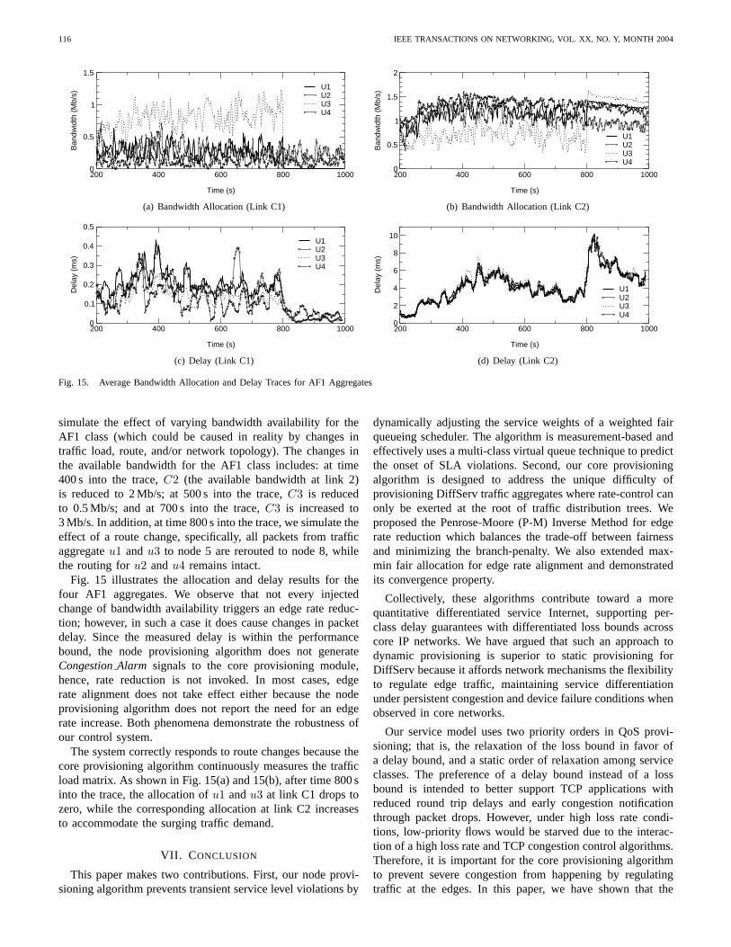
116 IEEE TRANSACTIONS ON NETWORKING, VOL. XX, NO. Y, MONTH 2004
200 400 600 800 1000
Time (s)
0
0.5
1
1.5B
andw
idth
(M
b/s)
U1U2U3U4
(a) Bandwidth Allocation (Link C1)
200 400 600 800 1000
Time (s)
0
0.5
1
1.5
2
Ban
dwid
th (
Mb/
s)
U1U2U3U4
(b) Bandwidth Allocation (Link C2)
200 400 600 800 1000
Time (s)
0
0.1
0.2
0.3
0.4
0.5
Del
ay (
ms)
U1U2U3U4
(c) Delay (Link C1)
200 400 600 800 1000
Time (s)
0
2
4
6
8
10
Del
ay (
ms)
U1U2U3U4
(d) Delay (Link C2)
Fig. 15. Average Bandwidth Allocation and Delay Traces for AF1 Aggregates
simulate the effect of varying bandwidth availability for theAF1 class (which could be caused in reality by changes intraffic load, route, and/or network topology). The changes inthe available bandwidth for the AF1 class includes: at time400 s into the trace,C2 (the available bandwidth at link 2)is reduced to 2 Mb/s; at 500 s into the trace,C3 is reducedto 0.5 Mb/s; and at 700 s into the trace,C3 is increased to3 Mb/s. In addition, at time 800 s into the trace, we simulate theeffect of a route change, specifically, all packets from trafficaggregateu1 andu3 to node 5 are rerouted to node 8, whilethe routing foru2 andu4 remains intact.
Fig. 15 illustrates the allocation and delay results for thefour AF1 aggregates. We observe that not every injectedchange of bandwidth availability triggers an edge rate reduc-tion; however, in such a case it does cause changes in packetdelay. Since the measured delay is within the performancebound, the node provisioning algorithm does not generateCongestionAlarm signals to the core provisioning module,hence, rate reduction is not invoked. In most cases, edgerate alignment does not take effect either because the nodeprovisioning algorithm does not report the need for an edgerate increase. Both phenomena demonstrate the robustness ofour control system.
The system correctly responds to route changes because thecore provisioning algorithm continuously measures the trafficload matrix. As shown in Fig. 15(a) and 15(b), after time 800 sinto the trace, the allocation ofu1 andu3 at link C1 drops tozero, while the corresponding allocation at link C2 increasesto accommodate the surging traffic demand.
VII. C ONCLUSION
This paper makes two contributions. First, our node provi-sioning algorithm prevents transient service level violations by
dynamically adjusting the service weights of a weighted fairqueueing scheduler. The algorithm is measurement-based andeffectively uses a multi-class virtual queue technique to predictthe onset of SLA violations. Second, our core provisioningalgorithm is designed to address the unique difficulty ofprovisioning DiffServ traffic aggregates where rate-control canonly be exerted at the root of traffic distribution trees. Weproposed the Penrose-Moore (P-M) Inverse Method for edgerate reduction which balances the trade-off between fairnessand minimizing the branch-penalty. We also extended max-min fair allocation for edge rate alignment and demonstratedits convergence property.
Collectively, these algorithms contribute toward a morequantitative differentiated service Internet, supporting per-class delay guarantees with differentiated loss bounds acrosscore IP networks. We have argued that such an approach todynamic provisioning is superior to static provisioning forDiffServ because it affords network mechanisms the flexibilityto regulate edge traffic, maintaining service differentiationunder persistent congestion and device failure conditions whenobserved in core networks.
Our service model uses two priority orders in QoS provi-sioning; that is, the relaxation of the loss bound in favor ofa delay bound, and a static order of relaxation among serviceclasses. The preference of a delay bound instead of a lossbound is intended to better support TCP applications withreduced round trip delays and early congestion notificationthrough packet drops. However, under high loss rate condi-tions, low-priority flows would be starved due to the interac-tion of a high loss rate and TCP congestion control algorithms.Therefore, it is important for the core provisioning algorithmto prevent severe congestion from happening by regulatingtraffic at the edges. In this paper, we have shown that the

LIAO AND CAMPBELL: DYNAMIC CORE PROVISIONING FOR QUANTITATIVE DIFFERENTIATED SERVICES 117
node provisioning algorithm can provide reliable early warningsignals using a virtual queue technique, which does not requireprior knowledge of traffic characteristics. We are currentlystudying how to extend the core provisioning algorithm to alsoprovide loss guarantees across traffic classes. This problembears similarity to the measurement based admission controlalgorithms discussed in the related work section (Section II).
The complexity of the proposed algorithms mainly residesin the node provisioning algorithm, which is distributed acrosscore routers and is scalable to large network configurations.The challenge of implementing the centralized core provi-sioning algorithm lies in the continuous monitoring of thetraffic matrix across the core network. To improve scalability,we a studying approaches that can enlarge the monitoringgranularity and time scale; for example, focusing on a fewpotential bottleneck links instead of every internal link in thenetwork, or, increasing theupdate interval provisioning timescale. Recent work on network measurement [11], [12], [25]of the AT&T backbone network provides valuable insights anddirections on how we could scale the monitoring process up tohandle large networks. The centralized approach to the currentdesign of the core provisioning algorithm provides a betterresponse time to sudden changes in network traffic overloads.To improve survivability against network failures (e.g., out-ages, DDoS), fault tolerant practices in network managementcan be used to deploy redundant core provisioning algorithms.We are currently studying a fully distributed core provisioningalgorithm that removes the single point of failure presentedby the existing centralized scheme. A key challenge is todesign and analyze the convergence and stability propertiesof a distributed solution in order to recover in a timelyfashion after network failure. We plan to develop some form ofanalytical proof or argument guaranteeing the stability of sucha scheme subject to the perturbations unbounded in magnitude,but bounded in time.
ACKNOWLEDGMENTS
This work is funded in part by a grant from the IntelCorporation for “Signaling Engine for Programmable IXANetworks”. We would also like to thank the anonymousreviewers and the editor for their constructive comments toimprove the quality of this paper.
REFERENCES
[1] S. B. et. al., “An Architecture for Differentiated Services,” IETF RFC2475, December 1998, http://www.ietf.org/rfc/rfc2475.txt.
[2] B. Teitelbaum, S. Hares, L. Dunn, R. Neilson, V. Narayan, andF. Reichmeyer, “Internet2 QBone: Building a Testbed for DifferentiatedServices,”IEEE Network Mag., pp. 8–16, September/October 1999.
[3] R. Rajan, D. Verma, S. Kamat, E. Felstaine, and S. Herzog, “A PolicyFramework for Integrated and Differentiated Services in the Internet,”IEEE Network Mag., pp. 36–41, September/October 1999.
[4] R. J. Gibbens and F. P. Kelly, “Distributed Connection AcceptanceControl for a Connectionless Network,” inProc. IEE Int’l TeletrafficCongress (ITC). Edinburgh, UK: Elsevier Science Publishers B.V.,June 1999.
[5] F. P. Kelly, P. B. Key, and S. Zachary, “Distributed Admission Control,”IEEE J. Select. Areas Commun., vol. 18, no. 12, pp. 2617–2628,December 2000, special Issue on QOS in the Internet.
[6] I. Stoica, S. Shenker, and H. Zhang, “Core-Stateless Fair Queueing:A Scalable Architecture to Approximate Fair Bandwidth Allocations inHigh Speed Networks,” inProc. Annual Conference of the ACM SpecialInterest Group on Data Commun. (SIGCOMM), September 1998.
[7] I. Stoica and H. Zhang, “Providing Guaranteed Services Without PerFlow Management,” inProc. Annual Conference of the ACM SpecialInterest Group on Data Commun. (SIGCOMM), September 1999.
[8] D. Mitra, J. Morrison, and K. G. Ramakrishnan, “Virtual PrivateNetworks: Joint Resource Allocation and Routing Design,” inProc.IEEE Annual Conference on Computer Commun. (INFOCOM), NewYork City, March 1999.
[9] F. P. Kelly, “Routing in Circuit-switched Networks: Optimization,Shadow Price and Decentralization,”Adv. Appl. Prob., vol. 20, pp. 112–144, 1988.
[10] A. Feldmann, A. Greenberg, C. Lund, N. Reingold, J. Rexford, andF. True, “NetScope: Traffic Engineering for IP Networks,”IEEE NetworkMag., March/April 2000.
[11] ——, “Deriving Traffic Demands for Operational IP Networks: Method-ology and Expeience,” inProc. Annual Conference of the ACM SpecialInterest Group on Data Commun. (SIGCOMM), September 2000.
[12] N. Duffield, P. Goyal, A. Greenberg, P. Mishra, K. K. Ramakrishnan,and J. E. van der Merwe, “A Flexible Model for Resource Managementin Virtual Private Networks,” inProc. Annual Conference of the ACMSpecial Interest Group on Data Commun. (SIGCOMM), September1999.
[13] C. Cetinkaya and E. Knightly, “Egress Admission Control,” inProc.IEEE Annual Conference on Computer Commun. (INFOCOM), Tel Aviv,Israel, March 2000.
[14] L. Breslau, E. Knightly, S. Shenker, I. Stoica, and H. Zhang, “EndpointAdmission Control: Architectural Issues and Perormance,” inProc. An-nual Conference of the ACM Special Interest Group on Data Commun.(SIGCOMM), Stockholm, Sweden, September 2000.
[15] C. Dovrolis, D. Stiliadis, and P. Ramanathan, “Proportional Differ-entiated Services: Delay Differentiation and Packet Scheduling,” inProc. Annual Conference of the ACM Special Interest Group on DataCommun. (SIGCOMM), September 1999.
[16] J. Liebeherr and N. Christin, “JoBS: Joint Buffer Management andScheduling for Differentiated Services,” inProc. IEEE/IFIP Int’l Work-shop on Quality of Service (IWQOS), Karlsruhe, Germany, June 2001.
[17] P. Hurley, M. Kara, J.-Y. L. Boudec, and P. Thiran, “A Novel Schedulerfor a Low Delay Service within Best-Effort,” inProc. IEEE/IFIP Int’lWorkshop on Quality of Service (IWQOS), Karlsruhe, Germany, June2001.
[18] Z. Zhang, Z. Duan, L. Gao, and Y. Hou, “Decoupling QOS Controlfrom Core Routers: A Novel Bandwidth Broker Architecture for ScalableSupport of Guaranteed Services,” inProc. Annual Conference of theACM Special Interest Group on Data Commun. (SIGCOMM), September2000.
[19] E. Rosen, A. Viswanathan, and R. Callon, “Multiprotocol Label Switch-ing (MPLS) Architecture,” IETF RFC 3031, January 2001.
[20] E. Bouillet, D. Mitra, and K. G. Ramakrishnan, “Design-Assisted,Real Time, Measurement-Based Network Controls for Management ofService Level Agreements,” inProceedings of EURANDOM Workshopon Stochastics of Integrated-Services Comm. Networks, Eindhoven, TheNetherlands, November 15-19 1999.
[21] C. Albuquerque, B. J. Vickers, and T. Suda, “Network Border Patrol,”in Proc. IEEE Annual Conference on Computer Commun. (INFOCOM),Tel Aviv, Israel, March 2000.
[22] R. R.-F. Liao and A. T. Campbell, “Dynamic Edge Provisioning for CoreNetworks,” in Proc. IEEE/IFIP Int’l Workshop on Quality of Service(IWQOS), Pittsburgh, USA, June 2000.
[23] S. Keshav,An Engineering Approach to Computer Networking: ATMNetworks, the Internet, and the Telephone Network. Reading, Mass.:Addison-Wesley, 1997.
[24] M. Mathis, J. Semke, J. Mahdavi, and T. Ott, “The MacroscopicBehavior of the TCP Congestion Avoidance Algorithm,”ACM Comput.Commun. Review, vol. 27, 1997.
[25] N. G. Duffield and M. Grossglauser, “Trajectory Sampling for DirectTraffic Observation,” inProc. Annual Conference of the ACM SpecialInterest Group on Data Commun. (SIGCOMM), September 2000.
[26] H. W. Kuhn and A. W. Tucker, “Non-linear Programming,” inProc.2nd Berkeley Symp. on Mathematical Statistics and Probability. Univ.Calif. Press, 1951, pp. 481–492.
[27] S. Campbell and C. M. Jr,Generalized Inverses of Linear Transforma-tions. London, UK: Pitman, 1979.
[28] D. Bertsekas and R. Gallager,Data Networks. Englewood Cliffs, NJ:Prentice-Hall, 1992.

118 IEEE TRANSACTIONS ON NETWORKING, VOL. XX, NO. Y, MONTH 2004
[29] UCB/LBNL/VINT, “Network Simulator - ns, DiffServ Module,”www.isi.edu/nsnam/ns/ns-contributed.html.
Raymond R.-F. Liao is currently working on tech-nology transfer of part of his Ph.D. research atSiemens TTB in Berkeley, CA. Raymond receivedhis Ph.D. from Columbia University in Dec. 2002.His thesis won the Eliah I. Jury award from theElectrical Engineering Department. He received theM.A.Sc. degree in 1993 and the B.E. degree in1990. Between 1993 and 1996, Raymond worked atNewbridge Networks Corp. on ATM network trafficmanagement. Raymond’s research interests includeperformance analysis, network adaptive services and
incentive engineering. He has (co)authored two dozen publications and severalpatents in these areas.
Andrew T. Campbell is an Associate Professor ofElectrical Engineering at Columbia University anda member of the COMET Group. He is workingon emerging architectures and programmability forwireless networks. Andrew received his Ph.D. inComputer Science in 1996 and the NSF CAREERAward for his research in programmable mobilenetworking in 1999.