Embed Size (px)
Citation preview

PUBLIC R
EVIEW DRAFT
DRAFT UGANDA STANDARD
DUS EAS 426-1
First Edition 2016-mm-dd
Reference number DUS EAS 426-1: 2006
© UNBS 2016
Concrete pipes and ancillary concrete products — Part 1: Specification for unreinforced and reinforced concrete pipes (including jacking pipes) and fittings with flexible joints

PUBLIC R
EVIEW DRAFT
DUS EAS 426-1:2006
ii © UNBS 2016 - All rights reserved
Compliance with this standard does not, of itself confer immunity from legal obligations
A Uganda Standard does not purport to include all necessary provisions of a contract. Users are responsible for its correct application
© UNBS 2016
All rights reserved. Unless otherwise specified, no part of this publication may be reproduced or utilised in any form or by any means, electronic or mechanical, including photocopying and microfilm, without prior written permission from UNBS.
Requests for permission to reproduce this document should be addressed to
The Executive Director Uganda National Bureau of Standards P.O. Box 6329 Kampala Uganda Tel: 256 417 333 250/1/2/3 Fax: 256 414 286 123 E-mail: [email protected] Web: www.unbs.go.ug

PUBLIC R
EVIEW DRAFT
DUS EAS 426-1:2006
© UNBS 2016 - All rights reserved iii
National foreword
Uganda National Bureau of Standards (UNBS) is a parastatal under the Ministry of Trade, Industry and Cooperatives established under Cap 327, of the Laws of Uganda, as amended. UNBS is mandated to co-ordinate the elaboration of standards and is
(a) a member of International Organisation for Standardisation (ISO) and
(b) a contact point for the WHO/FAO Codex Alimentarius Commission on Food Standards, and
(c) the National Enquiry Point on TBT Agreement of the World Trade Organisation (WTO).
The work of preparing Uganda Standards is carried out through Technical Committees. A Technical Committee is established to deliberate on standards in a given field or area and consists of representatives of consumers, traders, academicians, manufacturers, government and other stakeholders.
Draft Uganda Standards adopted by the Technical Committee are widely circulated to stakeholders and the general public for comments. The committee reviews the comments before recommending the draft standards for approval and declaration as Uganda Standards by the National Standards Council.
This Draft Uganda Standard, DUS EAS 426-1: 2006, Concrete pipes and ancillary concrete products — Part 1: Specification for unreinforced and reinforced concrete pipes (including jacking pipes) and fittings with flexible joints, is identical with and has been reproduced from an East African Standard, EAS 426-1: 2006, Concrete pipes and ancillary concrete products — Part 1: Specification for unreinforced and reinforced concrete pipes (including jacking pipes) and fittings with flexible joints, and is being proposed for adoption as a Uganda Standard.
This standard was developed by the Building and civil engineering Standards Technical Committee (UNBS/TC 3).
Wherever the words, “East African Standard" appear, they should be replaced by "Uganda Standard."

PUBLIC R
EVIEW DRAFT
EAS 426-1:2006 ICS 91.140.80 HS 6810.20.00 HS 6810.91.00
© EAC 2006 First Edition 2006
EAST AFRICAN STANDARD Concrete pipes and ancillary concrete products — Part 1: Specification for unreinforced and reinforced concrete pipes (including jacking pipes) and fittings with flexible joints
EAST AFRICAN COMMUNITY

PUBLIC R
EVIEW DRAFT
EAS 426-1:2006
ii © EAC 2006 — All rights reserved
Table of contents 1 Scope ..........................................................................................................................................1 3 Terms and definitions...................................................................................................................2 4 Symbols.......................................................................................................................................3 5 General requirements ..................................................................................................................3
5.1 Application...........................................................................................................................3 5.2 Concrete (4.2) .....................................................................................................................3 5.3 Finish (4.3.2) .......................................................................................................................5 5.4 Geometrical characteristics (4.3.3) ......................................................................................6 5.5 Durability of joints (4.3.4.2)..................................................................................................8 5.6 Crushing strength (4.3.5).....................................................................................................8 5.7 Lifting anchorages ............................................................................................................. 10 5.8 Bends (4.3.3.3).................................................................................................................. 10
6 Special requirements ................................................................................................................. 11 6.1 Reinforced concrete units..................................................................................................11
7 Conformity evaluation ................................................................................................................ 11 7.1 Application......................................................................................................................... 11 7.2 Finish ................................................................................................................................ 11 7.3 Geometrical characteristics ............................................................................................... 11 7.4 Lifting anchorages ............................................................................................................. 11
8 Marking...................................................................................................................................... 11 Annex A (informative) Information to be supplied in an enquiry or order ............................................ 12 Annex B (normative) British Standards relevant to EAS 419 .............................................................. 13 Annex C (normative) Surface finish tests............................................................................................ 14 Annex D (normative) Dimensional tests ............................................................................................. 16 Annex E (normative) Lifting anchorage pull-out test ........................................................................... 20 Bibliography ....................................................................................................................................... 21
PUBLIC R
EVIEW DRAFT
EAS 426-1:2006
© EAC 2006 — All rights reserved iii
Foreword Development of the East African Standards has been necessitated by the need for harmonizing requirements governing quality of products and services in East Africa. It is envisaged that through harmonized standardization, trade barriers which are encountered when goods and services are exchanged within the Community will be removed. In order to achieve this objective, the Partner States in the Community through their National Bureaux of Standards, have established an East African Standards Committee.
The Committee is composed of representatives of the National Standards Bodies in Partner States, together with the representatives from the private sectors and consumer organizations. Draft East African Standards are circulated to stakeholders through the National Standards Bodies in the Partner States. The comments received are discussed and incorporated before finalization of standards, in accordance with the procedures of the Community.
East African Standards are subject to review, to keep pace with technological advances. Users of the East African Standards are therefore expected to ensure that they always have the latest versions of the standards they are implementing.
© East African Community 2006 — All rights reserved*
East African Community
P O Box 1096
Arusha
Tanzania
Tel: 255 27 2504253/8
Fax: 255-27-2504481/2504255
E-Mail: [email protected]
Web: www.each.org
[Based on BS 5911-1:2002]
*
© 2005 EAC — All rights of exploitation in any form and by any means reserved worldwide for EAC Partner States’ NSBs.

PUBLIC R
EVIEW DRAFT

PUBLIC R
EVIEW DRAFT
EAS 426-1:2006
© EAC 2006 — All rights reserved 1
Concrete pipes and ancillary concrete products — Part 1: Specification for unreinforced and reinforced concrete pipes (including jacking pipes) and fittings with flexible joints
1 Scope EAS 419 specifies requirements and describes test methods for precast concrete pipes and fittings, unreinforced, steel fibre and reinforced, with flexible joints and nominal sizes not exceeding DN 1750 or WN/HN 1200/1800, for which the main intended use is the conveyance of sewage, rainwater and surface water under gravity or occasionally at low head of pressure in pipelines that are generally buried. The scope includes pipes (collectively referred to as “jacking pipes”) intended to be installed by pipe jacking, microtunnelling or other trenchless technology. This part of EAS 426 specifies complementary requirements to those in EAS 419 for unreinforced and reinforced concrete pipes and fittings, as provided for in that European Standard, with nominal sizes not exceeding DN 1500 for circular pipes with base and WN/HN 800/1200 for egg-shaped pipes. Full requirements for reinforced concrete circular trench and jacking pipes with nominal sizes greater than DN 1750, but not exceeding DN 3000, are also specified. In addition to pipes and fittings having a circular cross-section, EAS 419 also covers circular pipes with base and egg-shaped pipes. 2 Normative references The following referenced documents are indispensable for the application of this document. For dated references, only the edition cited applies. For undated references, the latest edition of the referenced document (including any amendments) applies. BS 146, Specification for blastfurnace cements with strength properties outside the scope of EAS 18-1 BS 3123, Specification for spring calipers and spring dividers BS 3892-1, Pulverized-fuel ash — Part 1: Specification for pulverized-fuel ash for use with Portland cement BS 4027, Specification for sulfate-resisting Portland cement BS 4035, Specification for linear measuring instruments for use on building and civil engineering constructional works — Steel measuring tapes, steel bands and retractable steel pocket rules BS 4449, Specification for carbon steel bars for the reinforcement of concrete BS 4482, Specification for cold reduced steel wire for the reinforcement of concrete BS 4483, Steel fabric for the reinforcement of concrete BS 4484-1, Specification for measuring instruments for constructional works — Part 1: Metric graduation and figuring of instruments for linear measurement BS 4921:1998, Specification for sherardized coatings on iron or steel BS 4994, Specification for design and construction of vessels and tanks in reinforced plastics
EAST AFRICAN STANDARD

PUBLIC R
EVIEW DRAFT
EAS 426-1:2006
2 © EAC 2006 — All rights reserved
BS 5204-1, Specification for straightedges — Part 1: Cast iron straightedges (bow shaped and I-section) BS 5204-2, Specification for straightedges — Part 2: Steel or granite straightedges of rectangular section BS 5480, Specification for glass reinforced plastics (GRP) pipes, joints and fittings for use for water supply or sewerage BS 6699, Specification for ground granulated blastfurnace slag for use with Portland cement EAS 18-1, Cement — Part 1: Composition, specifications and conformity criteria for common cements BS EN 681-1, Elastomeric seals — Material requirements for pipe joint seals used in water and drainage applications — Part 1: Vulcanized rubber BS EN 934-2, Admixtures for concrete, mortar and grout — Part 2: Concrete admixtures — Definitions, requirements, conformity, marking and labelling BS EN 1008, Mixing water for concrete — Specification for sampling, testing and assessing the suitability of water, including water recovered from processes in the concrete industry, as mixing water for concrete. BS EN 1011-2, Welding — Recommendations for welding of metallic materials — Part 2: Arc welding of ferritic steels BS EN 1011-3, Welding — Recommendations for welding of metallic materials — Part 3: Arc welding of stainless steels EAS 419, Concrete pipes and fittings, unreinforced, steel fibre and reinforced
BS EN 10025:1993, Hot rolled products of non-alloy structural steels — Technical delivery conditions.
BS EN 10088-2:1995, Stainless steels — Part 2: Technical delivery conditions for sheet/plate and strip for general purposes EAS 180, Aggregates for concrete ISO 1461, Hot dip galvanized coatings on fabricated iron and steel articles — Specifications and test methods 3 Terms and definitions For the purposes of this part of EAS 426, the terms and definitions given in EAS 419 and the following apply. 3.1 cementitious content amount of cement plus any pozzolanic or latent hydraulic addition in the concrete mix
3.2 circular unit circular pipe (including a jacking pipe) or fitting for use with such a pipe 3.3 circular pipe with base circular pipe strengthened on the outside at the base 3.4 egg-shaped geometric form as typically shown in Figure 1

PUBLIC R
EVIEW DRAFT
EAS 426-1:2006
© EAC 2006 — All rights reserved 3
Figure 1 — Typical geometric form for an egg-shaped bore
3.5 lifting anchorage device cast within the wall of a unit to facilitate lifting 3.6 manufacturing diameter diameter of a circular unit that a manufacturer seeks to achieve 4 Symbols
The meanings of symbols used in this part of EAS 426 shall be as given in Table 1 below, together with those in Table 2 of EAS 419.
Table 1 — Symbols
Symbol Meaning Unit Reference
spp Deviation of spigot end mm D.5.1.3
sop Deviation of spigot end mm D.5.1.3
sh Height of studs on straightness gauge mm D.4.2
'l Internal barrel length minus 0.1 m m D.4.2
yx ll , Opposite measured internal barrel lengths mm D.5.1.3
yx cc , Opposite measured internal diagonals mm D.5.1.3
5 General requirements NOTE The numbers in brackets after subclause headings are the corresponding subclause numbers in EAS 419. 5.1 Application
For pipes and fittings with nominal sizes not exceeding DN 1750 or WN/HN 800/1200 the requirements of this part of EAS 426 shall be in addition to those specified in EAS 419 and for the purposes of the latter the reference specifications shall be those listed in Annex B of this Standard. For reinforced concrete circular trench and jacking pipes with nominal sizes greater than DN 1750 the requirements of EAS 419 shall also apply, except as otherwise required by, or stated in, this part of EAS 426. 5.2 Concrete (4.2) 5.2.1 Composition 5.2.1.1 Types of cement

PUBLIC R
EVIEW DRAFT
EAS 426-1:2006
4 © EAC 2006 — All rights reserved
The cement (see EAS 419, 4.1) shall either:
a) be factory-produced by the cement manufacturer and conform to one of the following Standards as appropriate:
Type of cement Standard CEM I EAS 18-1 CEM II/B-V EAS 18-1 BIII/B BS 146 sulfate-resisting Portland BS 4027; or
b) consist of a combination of cement conforming to CEM I as specified in EAS 18-1 and an addition in the form of ground granulated blastfurnace slag (ggbs) or pulverized-fuel ash (pfa) in the proportions specified in 5.2.1.2, to be included as part of the concrete mix by simultaneously combining them with the other concrete materials at the concrete mixer.
In all cases where combinations of cement conforming to CEM I as specified in EAS 18-1 and ggbs or pfa are used, the relevant proportion of ggbs or pfa shall be fully documented in the production records. 5.2.1.2 Cementitious content
The fully compacted concrete shall have a minimum cementitious content of not less than the relevant amount shown in Table 2. The composition/specification of cement groups shall be as shown in Table 3.
Table 2 — Cementitious contenta
Classb Aggregate carbonate rangec
Cement or combination group
Minimum cement or combination content kg/m3
Maximum w/c ratio
DC-2 A, B, C 1, 2, 3 340 0.45 A 2a 400 0.40 A 2b, 3 380 0.45
DC-3
B, C 2, 3 340 0.45 DC-3* B 2, 3 380 0.45 DC-3* * C 2, 3 380 0.45
A 2a 400 0.35 A 2b, 3 400 0.40 A 2, 3 380 0.33 B, C 2, 3 380 0.45
DC-4
B, C 2, 3 360 0.40 B 2, 3 380 0.33 DC-4* B 2, 3 400 0.40 C 2, 3 380 0.33 DC-4* * C 2, 3 400 0.40 A 2b, 3 380 0.33 A 2b, 3 400 0.40 B 3 400 0.40 B, C 3 360 0.40
DC-4m
B, C 3 380 0.45 DC-4m* B 3 380 0.33
C 3 380 0.33 DC-4m* * C 3 400 0.40
a The table is consistent with the provisions of BS 8500-1:2002 and BRE Special Digest 1 [1] insofar as they relate to precast concrete pipeline systems, except that the maximum water/cement (w/c) ratio is limited to 0.45 in accordance with EAS 419, 4.2.3.2. b The class designations are those for design chemical class (DC-class) in EAS 417-1, Table A.15. Where there is more than one option in a class the choice is at the manufacturer’s discretion. c See BRE Special Digest 1 - Part 4, Table 4.
Table 3 — Cement or combination groupsa
Type (see 5.2.1.1) Designation Standard Grouping with respect to sulfate resistance
PUBLIC R
EVIEW DRAFT
EAS 426-1:2006
© EAC 2006 — All rights reserved 5
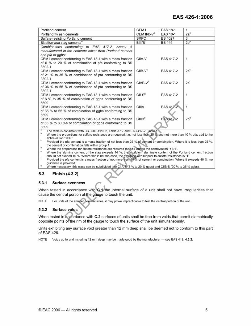
Portland cement CEM I EAS 18-1 1 Portland fly ash cements CEM II/B-Vb EAS 18-1 2ac Sulfate-resisting Portland cement SRPC BS 4027 3 Blastfurnace slag cementse BIII/Bd BS 146 2be Combinations conforming to EAS 417-2, Annex A manufactured in the concrete mixer from Portland cement and pfa or ggbs:
CEM I cement conforming to EAS 18-1 with a mass fraction of 6 % to 20 % of combination of pfa conforming to BS 3892-1
CIIA-V EAS 417-2 1
CEM I cement conforming to EAS 18-1 with a mass fraction of 21 % to 35 % of combination of pfa conforming to BS 3892-1
CIIB-Vb EAS 417-2 2ac
CEM I cement conforming to EAS 18-1 with a mass fraction of 36 % to 55 % of combination of pfa conforming to BS 3892-1
CIVB-Vb EAS 417-2 2af
CEM I cement conforming to EAS 18-1 with a mass fraction of 6 % to 35 % of combination of ggbs conforming to BS 6699
CII-Sg EAS 417-2 1
CEM I cement conforming to EAS 18-1 with a mass fraction of 36 % to 65 % of combination of ggbs conforming to BS 6699
CIIIA EAS 417-2 1
CEM I cement conforming to EAS 18-1 with a mass fraction of 66 % to 80 %e of combination of ggbs conforming to BS 6699
CIIIBd EAS 417-2 2be
a The table is consistent with BS 8500-1:2002, Table A.17 and EAS 417-2, Table 1. b Where the proportions for sulfate resistance are required, i.e. not less than 25 % and not more than 40 % pfa, add to the abbreviation “+SR”. c Provided the pfa content is a mass fraction of not less than 25 % of cement or combination. Where it is less than 25 %, the cement of combination falls within group 1. d Where the proportions for sulfate resistance are required (see e), add to the abbreviation “+SR”. e Where the alumina content of the slag exceeds 14 %, the tricalcium aluminate content of the Portland cement fraction should not exceed 10 %. Where this is not the case, the grouping with respect to sulfate resistance is “1”. f Provided the pfa content is a mass fraction of not more than 40 % of cement or combination. Where it exceeds 40 %, no guidance is provided. g Where necessary, this class can be subdivided into CIIA-S (6 % to 20 % ggbs) and CIIB-S (20 % to 35 % ggbs).
5.3 Finish (4.3.2) 5.3.1 Surface evenness
When tested in accordance with C.1 the internal surface of a unit shall not have irregularities that cause the central portion of the gauge to touch the unit. NOTE For units of the smaller nominal sizes, it may prove impracticable to test the central portion of the unit. 5.3.2 Surface voids
When tested in accordance with C.2 surfaces of units shall be free from voids that permit diametrically opposite points of the rim of the gauge to touch the surface of the unit simultaneously.
Units exhibiting any surface void greater than 12 mm deep shall be deemed not to conform to this part of EAS 426. NOTE Voids up to and including 12 mm deep may be made good by the manufacturer — see EAS 419, 4.3.2.

PUBLIC R
EVIEW DRAFT
EAS 426-1:2006
6 © EAC 2006 — All rights reserved
5.4 Geometrical characteristics (4.3.3)
5.4.1 General
Subject to the requirements of this clause, the internal and external dimensions and wall thickness of units, and the configuration of bends, shall conform to those stated in the factory documents.
5.4.2 Nominal sizes NOTE Nominal size is defined in EAS 419, 3.1.16 as a numerical designation of the size of a unit, which is a convenient integer approximately equal to the manufacturing dimension in millimetres; for a circular unit it is the internal diameter (DN), and for a unit with an egg-shaped bore it is the internal width/height (WN/HN).
The nominal sizes of circular units and circular units with base, for use in trench construction, shall be those given in Table 4.
The nominal sizes of egg-shaped units shall be those given in Table 5.
The nominal sizes of jacking pipes shall be either:
a) those given in Table 6; or
b) other nominal sizes halfway between the sizes given in Table 6 with the proviso that the limits on internal manufacturing diameter shall be those for the next higher nominal size given in Table 6.
5.4.3 Internal dimensions of egg-shaped units
The internal width/height of egg-shaped units shall be as given in Table 5.
5.4.4 Manufacturing diameters of jacking pipes
The manufacturer shall make available, at the enquiry stage, information on the internal and external manufacturing diameters of jacking pipes that can be supplied (see Annex A).
The internal manufacturing diameters of jacking pipes shall be not outside the limits given in Table 6.
The external manufacturing diameters of jacking pipes shall be stated in the factory documents.
Table 4 — Nominal sizes and tolerances of units with a circular bore, for use in a trench
Nominal size [DN] Tolerance on actual diameter from nominal size [mm]
225 ±5 300 ±5 375* ±5 400 ±5 450* ±5 500 ±6 525* ±6 600 ±6 675* ±6 700 ±7 750* ±7 800 ±7 825* ±7 900* ±8 1000 ±8 1050* ±8 1200 ±9 1350* ±10 1400 ±10 1500* ±11 1600 ±11 1800 ±12 2000 ±13 2100* ±14 2200 ±14 2400* ±15 2500 ±15 2800 ±15 3000 ±15 NOTE Classic sizes, denoted by an asterisk, will be phased out if called for by further European harmonization.

PUBLIC R
EVIEW DRAFT
EAS 426-1:2006
© EAC 2006 — All rights reserved 7
Table 5 — Nominal sizes and tolerances of egg-shaped units
Nominal size [WH/HN] Tolerance on actual width/height from nominal size [mm] 250/375 ±5 300/450 ±5 400/600 ±5 500/750 ±6 600/900 ±6 700/1050 ±7 800/1200 ±7
Table 6 — Nominal sizes, internal manufacturing diameter and tolerances of jacking pipes
Limits of internal manufacturing
diameter mm
Tolerance on actual diameter from manufacturer’s stated diameter a
mm
Nominal size
DN Minimum Maximum Internal External
450 440 460 ±5 ±4 500 490 525 ±6 ±4 600 580 610 ±6 ±4 700 675 720 ±7 ±4 800 770 825 ±7 ±4 900 875 950 ±8 ±4 1000 980 1 070 ±8 ±5 1200 1 180 1 220 ±9 ±5 1400 1 350 1 420 ±10 ±5 1500 1 470 1 530 ±11 ±5 1600 1 580 1 675 ±11 ±6 1800 1 780 1 830 ±12 ±6 2000 1 950 2 135 ±13 ±6 2200 2 170 2 250 ±14 ±7 2500 2 375 2 550 ±15 ±7 2800 2 680 2 850 ±15 ±7 3000 2 965 3 050 ±15 ±7 NOTE The values of certain limits of internal manufacturing diameter have been chosen to allow for utilization of existing manufacturing equipment during transition to a rationalized metric range of nominal sizes and also to suit the installation equipment, which controls the external diameter of jacking pipes. a See 3.6.
5.4.5 Dimensional tolerances 5.4.5.1 Tolerances on the internal diameter of units with a circular bore, for use in a trench The tolerances on the internal manufactured diameter of units with a circular bore, for use in a trench, shall be ±5 mm for nominal sizes up to and including DN 300 and ±(3 + 0.005DN) mm for larger nominal sizes (rounded to the nearest millimetre), limited to ±15 mm (see Table 4). No individual measurement, measured in accordance with D.2, shall be outside the specified limits. 5.4.5.2 Tolerances on the internal width/height of egg-shaped units The tolerances on the internal width/height of egg-shaped units shall be ±5 mm for nominal widths up to and including WN 300 and ±(3 + 0.005WN) mm for larger nominal widths (rounded to the nearest millimetre) (see Table 5). No individual measurement, measured in accordance with D.2, shall be outside the specified limits. 5.4.5.3 Tolerances on the internal diameter of jacking pipes The tolerances on the internal manufactured diameter of jacking pipes shall be ±(3 + 0.005DN) mm (rounded to the nearest millimetre), limited to ±15 mm (see Table 6). No individual measurement, measured in accordance with D.2, shall be outside the specified limits.

PUBLIC R
EVIEW DRAFT
EAS 426-1:2006
8 © EAC 2006 — All rights reserved
5.4.5.4 Tolerances on the external diameter of jacking pipes The tolerances on the external manufactured diameter of the barrel of a jacking pipe shall be as given in Table 6. No individual measurement, measured in accordance with D.3, shall be outside the specified limits. 5.4.5.5 Tolerance on the wall thickness Any value of wall thickness measured in accordance with D.4 shall be not less than the value stated in the factory documents. 5.4.5.6 Deviation from straightness When measured in accordance with D.5, for the internal straightness of a straight unit (and for jacking pipes, the external straightness) both ends of the gauge shall not make contact with the surface of the unit when using Edge X and the two studs shall be in contact simultaneously when using Edge Y. NOTE See Figure D.1. 5.4.5.7 Tolerance on the internal barrel length of jacking pipes When evaluated in accordance with D.5.1 the tolerance on the mean internal barrel length of jacking pipes up to a nominal size of DN 800 shall be ±10 mm. For pipes with a larger nominal size the tolerances on the internal barrel length shall be mm. Where pipes are designed for use with a method of installation that requires tighter manufacturing tolerances, these shall be stated in the factory documents and inspection procedures shall provide for the selection and marking of groups of pipes for delivery to a specific contract. 5.4.5.8 Squareness of ends Units shall be capable of being jointed with their axes coincident within the deflection limit specified in EAS 419, E.5.2; for circular units this requirement shall apply in any orientation. NOTE Squareness of ends of trench units is significant only to the extent that it relates to the performance of the joint assembly. When evaluated in accordance with D.5.1 and D.5.2 the ends of a jacking pipe shall conform to the requirements of Table 7 for squareness across a diameter and wall thickness.
Table 7 — Tolerances on the squareness of ends of jacking pipes
Nominal size DN
Maximum deviation across a diameter mm
Maximum deviation across wall thickness mm
DN ≤ 900 3 2 900 < DN ≤ 1500 3.5 3 1500 < DN ≤ 2100 5 4 2100 < DN ≤ 3000 6 5
5.5 Durability of joints (4.3.4.2) The durability of joints shall be demonstrated in accordance with EAS 419, 4.3.4.2 Method 1. 5.6 Crushing strength (4.3.5) 5.6.1 Strength classes and minimum crushing loads of units for trench use NOTE Strength class is defined in EAS 419, 3.1.19 as the minimum crushing load in kilonewtons per metre, divided by one thousandth of either a unit’s nominal size (DN) or nominal width (WN).

PUBLIC R
EVIEW DRAFT
EAS 426-1:2006
© EAC 2006 — All rights reserved 9
Units with a circular bore for trench use shall be strength class 120 with corresponding minimum crushing loads in accordance with Table 8. Egg-shaped units shall be strength class 150 with corresponding minimum crushing loads in accordance with Table 9. Units of other crushing strength shall be permitted only if their special strength class is separated by at least 20 % of the next lower value and that they conform to EAS 419 and this part of EAS 426 in all other respects. Minimum crushing loads corresponding to special strength classes shall be rounded up to the nearest kilonewton per metre (kN/m). 5.6.2 Strength classes and minimum crushing loads of jacking pipes Jacking pipes shall be strength class 120 with corresponding minimum crushing loads in accordance with Table 10. Pipes of other crushing strength shall be permitted only if their special strength class is separated by at least 20 % of the next lower value and that they conform to EAS 419 and this part of EAS 426 in all other respects. Minimum crushing loads corresponding to special strength classes shall be rounded up to the nearest kilonewton per metre (kN/m). Table 8 — Minimum crushing loads for strength class 120 units with a circular bore for use in a trench
Nominal size DN
Minimum crushing load, Fn kN/m
225 27 300 36 375* 45 400 48 450* 54 500 60 525* 63 600 72 675* 81 700 84 750* 90 800 96 825* 99 900* 108 1000 120 1050* 126 1200 144 1350* 162 1400 168 1500* 180 1600 192 1800 216 2000 240 2100* 252 2200 264 2400* 288 2500 300 2800 336 3000 360 NOTE 1 Classic sizes, denoted by an asterisk, will be phased out if called for by further European harmonization. NOTE 2 Sizes DN 225 to DN 600 inclusive are normally only manufactured unreinforced in the United Kingdom. NOTE 3 Sizes DN 1000 and above are normally only manufactured reinforced in the United Kingdom. NOTE 4 Table NA.5 of BS EN 1295-1:1998 recommends that the minimum value of safety factor for the structural design of reinforced pipelines should be increased from the normal 1.25 to 1.5 if, as is the case of EAS 419, the proof load is 67 % of the minimum crushing load.

PUBLIC R
EVIEW DRAFT
EAS 426-1:2006
10 © EAC 2006 — All rights reserved
Table 9 — Minimum crushing loads for strength class 150 egg-shaped units
Nominal size WN/LN
Minimum crushing load, Fn (rounded up to nearest kN/m)
250/375 38 300/450 45 400/600 60 500/750 75 600/900 90 700/1050 105 800/1200 120 NOTE Table NA.5 of BS EN 1295-1:1998 recommends that the minimum value of safety factor for the structural design of reinforced pipelines should be increased from the normal 1.25 to 1.5 if, as is the case of EAS 419, the proof load is 67 % of the minimum crushing load.
Table 10 — Minimum crushing loads for strength class 120 jacking pipes
Nominal size
DN Minimum crushing load, Fn
kN/m 450 54 500 60 600 72 700 84 800 96 900 108 1000 120 1200 144 1400 168 1500 180 1600 192 1800 216 2000 240 2200 264 2500 300 2800 336 3000 360 NOTE Table NA.5 of BS EN 1295-1:1998 recommends that the minimum value of safety factor for the structural design of reinforced pipelines should be increased from the normal 1.25 to 1.5 if, as is the case of EAS 419, the proof load is 67 % of the minimum crushing load.
5.7 Lifting anchorages A lifting anchorage shall be safe and fit for purpose as demonstrated in accordance with Annex E by the application of a test load equal to 2.5 times the maximum weight of the unit for which that lifting anchorage was designed to be used. Lifting anchorages shall be manufactured from steel conforming to BS EN 10025:1993, Grade 52.3 and have either a sherardized or galvanized coating in accordance with BS 4921:1988, Class 1 or ISO 1461 respectively. 5.8 Bends (4.3.3.3) For bends having subtended angles greater than 70°, the radius r as shown in Figure 3 of EAS 419 shall be a minimum of 0.7DN mm. NOTE Typical angles are 11° 15½, 22° 30½ and 45°.
PUBLIC R
EVIEW DRAFT
EAS 426-1:2006
© EAC 2006 — All rights reserved 11
6 Special requirements 6.1 Reinforced concrete units 6.1.1 Concrete cover (5.2.2) The minimum concrete cover shall be 15 mm, or the relevant nominal maximum size of aggregate stated in the factory documents, whichever is the larger. NOTE 1 The number in brackets after this subclause heading is the corresponding subclause number in EAS 419. NOTE 2 Given the inspection procedures specified in this part of EAS 426 and the maximum permitted stabilized surface crack width specified in EAS 419, 5.2.3 the value of minimum concrete cover is consistent with the serviceability conditions specified in EAS 419, 4.3.8. Taken together, these factors are also consistent with the crack control provisions given in BS 8110-1 and BS 8110-2. NOTE 3 Units conveying sea water, industrial waste, etc. and those to be installed in more aggressive serviceability conditions than those specified in EAS 419, 4.3.8 may need additional concrete cover. The advice of the pipe manufacturer should be sought in such a situation. NOTE 4 See EAS 419, 5.3.3 regarding the increased minimum concrete cover on external surfaces of jacking pipes to be in permanent contact with the ground. 7 Conformity evaluation 7.1 Application The conformity evaluation requirements of EAS 419 shall apply to this part of EAS 426, supplemented by the following sampling procedures. 7.2 Finish If subjected to either or both of the tests in Annex C the finish of any unit shall conform to 5.3.1 and 5.3.2 for surface evenness and surface voids respectively. 7.3 Geometrical characteristics Sampling procedures to evaluate the conformity of internal diameter, internal width/height, internal and external diameter of jacking pipes, wall thickness, straightness, internal barrel length of jacking pipes and squareness of ends to 5.4.4.1 to 5.4.4.8 respectively shall be in accordance with those for Geometrical characteristics — Units in Table H.1 of EAS 419. 7.4 Lifting anchorages Sampling procedures to evaluate the conformity of lifting anchorages to 5.7 shall comprise an initial type test for each nominal size and type of unit. 8 Marking In addition to the requirements in EAS 419, Clause 8 each unit shall be marked EAS 426-1 immediately following EAS 419 and with the letter “R” if it is a reinforced concrete unit. Special strength class units (see 5.6) shall also be marked with the relevant class.

PUBLIC R
EVIEW DRAFT
EAS 426-1:2006
12 © EAC 2006 — All rights reserved
Annex A (informative) Information to be supplied in an enquiry or order The following particulars cover essential details required by the manufacturer so that an enquiry or order may be fully understood: Reference in: EAS 419 EAS 426-1 a) type, quantity, cross-sectional shape(s) and nominal size(s) of units
3.1.15 5.4.1
b) any special strength class of units 4.3.5 5.2 c) if units are required to be reinforced 5.2.3 6.1 d) design chemical class (DC-class) of concrete in units 4.3.9 5.2.1 e) if additional concrete cover is required 4.3.9 and 5.2.2 6.1.1 f) type of joint and material of any collar for jacking pipes 5.3.1 ― g) dimensions and materials of inlets or branch pipes for junctions
5.4 ―
h) if lifting anchorages are required ― 5.7 i) if the products are to be fully covered by a third party certification scheme
7.1 Foreword

PUBLIC R
EVIEW DRAFT
EAS 426-1:2006
© EAC 2006 — All rights reserved 13
Annex B (normative) British Standards relevant to EAS 419 The reference specifications prescribed in 5.1 are listed in Table B.1. Table B.1 — British Standards relevant to EAS 419
Reference in EAS 419 Relevant British Standard Subclause number Material/Characteristic
EAS 18-1 BS 146
4.1 Cements
BS 4027 4.1 Aggregates EAS 180 4.1 Mixing water BS EN 1008a 4.1 Admixtures BS EN 934-2
BS 3892-1 4.1 Additions BS 6699 BS 4449 BS 4482
4.1 Reinforcing steel
BS 4483 4.1.2 and 4.3.3.2 Joint seals BS EN 681-1
Collars: — weldable structural steel plate BS EN 10025:1993 (Grade S275 or S275JR) — stainless steel plate BS EN 10088-2:1995 (Designation
X5CrNiMo17-12-2 [1.4401]) BS EN 1011-2 (ferritic steel) — welding BS EN 1011-3 (stainless steel) BS 4994 (hand laid-up)
5.3.1.2
— reinforced plastics BS 5480 (machine made)
a) BS EN 1008:2002, 3.1 specifies that potable water does not need testing.

PUBLIC R
EVIEW DRAFT
EAS 426-1:2006
14 © EAC 2006 — All rights reserved
Annex C (normative) Surface finish tests C.1 Surface evenness test C.1.1 Principle The purpose of this test is to evaluate whether the internal surface of a unit conforms to the limiting requirement in 5.3.1 for evenness. C.1.2 Apparatus C.1.2.1 Gauge, as described in Figure C.1.
Figure C.1 — Gauge for assessing surface evenness C.1.3 Procedure C.1.3.1 Place the gauge in the unit so that its axis is in the same plane as the unit’s longitudinal axis. C.1.3.2 Roll the gauge around the inside of the unit, taking care to ensure that its axis remains in the same plane as the unit’s longitudinal axis at all times. C.1.4 Expression of result Record whether the gauge rolled over any part of the internal surface without the central portion of the gauge contacting the unit. C.2 Surface void test C.2.1 Principle The purpose of this test is to evaluate whether any void in the surface of a unit conforms to the limiting requirements in 5.3.2. C.2.2 Apparatus C.2.2.1 Gauge, as described in Figure C.2.

PUBLIC R
EVIEW DRAFT
EAS 426-1:2006
© EAC 2006 — All rights reserved 15
Dimensions in mm
Figure C.2 ― Gauge for assessing surface voids C.2.3 Procedure Apply the ball of the gauge to the void. C.2.4 Expression of result Record whether diametrically opposite points in the rim of the gauge simultaneously touched the surface of the unit.
PUBLIC R
EVIEW DRAFT
EAS 426-1:2006
16 © EAC 2006 — All rights reserved
Annex D (normative) Dimensional tests NOTE At the manufacturer’s discretion it is permissible to use purpose-made “go/no-go” gauges for dimensional measurements in lieu of the apparatus specified for the tests in this Annex. D.1 Internal dimensions test D.1.1 Principle The purpose of this test is to evaluate whether the internal diameter of circular units and circular units with base for trench use, the width/height of egg-shaped units and the internal diameter of jacking pipes conform to 5.4.5.1, 5.4.5.2 and 5.4.5.3 respectively. D.1.2 Apparatus D.1.2.1 Steel measuring tape or retractable pocket rule, conforming to BS 4035, with metric graduation and figuring conforming to BS 4484-1. D.1.3 Procedure For units with a circular bore, make three measurements of the internal diameter at each end at approximately 60° to each other. For egg-shaped units, make a measurement of the horizontal and vertical axes at each end. For all units take the measurements at approximately 50 mm from the ends of the internal barrel and record the measurement. D.1.4 Expression of results Record whether each measured value of the internal diameter or width/height conforms to 5.4.5.1, 5.4.5.2 and 5.4.5.3 as appropriate. D.2 External diameter test for jacking pipes D.2.1 Principle The purpose of this test is to evaluate whether the external barrel of a jacking pipe conforms to 5.4.5.4. D.2.2 Apparatus D.2.2.1 Steel measuring tape, steel band or retractable pocket rule, conforming to BS 4035, with metric graduation and figuring conforming to BS 4484-1. D.2.3 Procedure Measure the external circumference of the pipe at approximately 50 mm from the ends of the barrel and record this measurement. Calculate the external diameter of the barrel from the measured circumference. D.2.4 Expression of results Record whether each measured value of the external diameter conforms to 5.4.5.4. D.3 Wall thickness test D.3.1 Principle The purpose of this test is to evaluate whether the wall thickness of a unit conforms to 5.4.5.5.

PUBLIC R
EVIEW DRAFT
EAS 426-1:2006
© EAC 2006 — All rights reserved 17
D.3.2 Apparatus D.3.2.1 Outside spring caliper, conforming to BS 3123. D.3.2.2 Steel measuring tape or retractable pocket rule, conforming to BS 4035, with metric graduation and figuring conforming to BS 4484-1. D.3.3 Procedure For circular units, measure the wall thickness at approximately 50 mm from the end of the external barrel at the spigot end, at three positions equidistant around the circumference of the unit. For circular units with base and egg-shaped units, measure the wall thickness at approximately 50 mm from the end of the external barrel at the crown, springing points and invert. D.3.4 Expression of results Record whether each measured value of the wall thickness conforms to 5.4.5.5. D.4 Straightness test D.4.1 Principle The purpose of this test is to evaluate whether the internal straightness, and for jacking pipes the external straightness, of a unit conforms to 5.4.5.6. D.4.2 Apparatus D.4.2.1 Rigid straightedge, made into a gauge of the form and dimensions shown in Figure D.1.
Dimensions in mm
hs = (3.5 l’ ± 5 %) in mm NOTE The studs should be detachable from the basic straightedge to facilitate checking and replacement.
Figure D.1 — Gauge for measuring deviation from straightness
D.4.3 Procedure D.4.3.1 Place the straightedge in the bore of the unit with Edge X (see Figure D.1) in contact with the unit and on a line parallel to its longitudinal axis. Hold the plane of the gauge in a radial plane and record whether both ends of the gauge, wherever so placed, were in contact with the internal surface of the unit. D.4.3.2 If both ends of the gauge were not in contact with the internal surface of the unit at both ends, reverse the gauge so that Edge Y, placed as above (see Figure D.1), is adjacent to the internal surface of the unit.
PUBLIC R
EVIEW DRAFT
EAS 426-1:2006
18 © EAC 2006 — All rights reserved
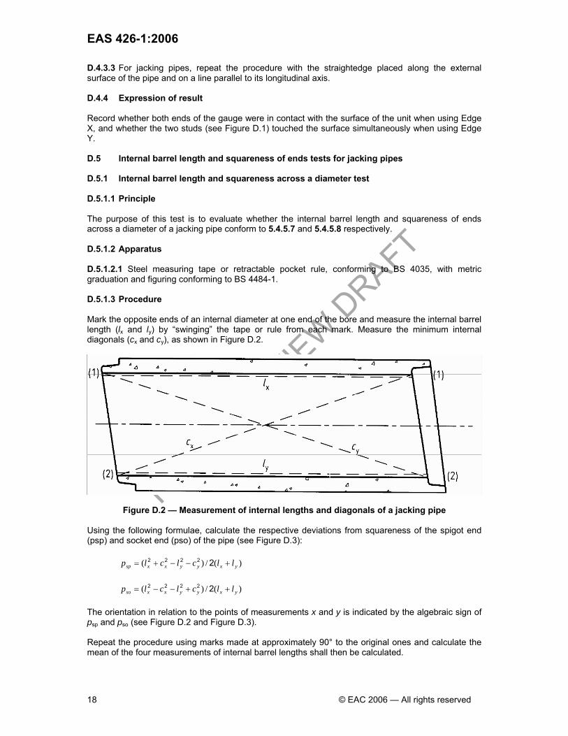
D.4.3.3 For jacking pipes, repeat the procedure with the straightedge placed along the external surface of the pipe and on a line parallel to its longitudinal axis. D.4.4 Expression of result Record whether both ends of the gauge were in contact with the surface of the unit when using Edge X, and whether the two studs (see Figure D.1) touched the surface simultaneously when using Edge Y. D.5 Internal barrel length and squareness of ends tests for jacking pipes D.5.1 Internal barrel length and squareness across a diameter test D.5.1.1 Principle The purpose of this test is to evaluate whether the internal barrel length and squareness of ends across a diameter of a jacking pipe conform to 5.4.5.7 and 5.4.5.8 respectively. D.5.1.2 Apparatus D.5.1.2.1 Steel measuring tape or retractable pocket rule, conforming to BS 4035, with metric graduation and figuring conforming to BS 4484-1. D.5.1.3 Procedure Mark the opposite ends of an internal diameter at one end of the bore and measure the internal barrel length (lx and ly) by “swinging” the tape or rule from each mark. Measure the minimum internal diagonals (cx and cy), as shown in Figure D.2.
Figure D.2 — Measurement of internal lengths and diagonals of a jacking pipe Using the following formulae, calculate the respective deviations from squareness of the spigot end (psp) and socket end (pso) of the pipe (see Figure D.3):
)(/)( yxyyxxsp llclclp +−−+= 22222
)(/)( yxyyxxso llclclp ++−−= 22222 The orientation in relation to the points of measurements x and y is indicated by the algebraic sign of psp and pso (see Figure D.2 and Figure D.3). Repeat the procedure using marks made at approximately 90° to the original ones and calculate the mean of the four measurements of internal barrel lengths shall then be calculated.

PUBLIC R
EVIEW DRAFT
EAS 426-1:2006
© EAC 2006 — All rights reserved 19
D.5.1.4 Expression of result Record whether the mean value of the four measurements of internal barrel length and each of the deviations from squareness across the diameter of the jacking pipe conformed to 5.4.5.7. D.5.2 Squareness across the wall thickness test D.5.2.1 Principle The purpose of this test is to evaluate whether the squareness across the wall thickness at the end of a jacking pipe conforms to 5.4.5.8. D.5.2.2 Apparatus D.5.2.2.1 Cast iron or steel straightedge, conforming to BS 5204-1 or BS 5204-2. D.5.2.2.2 Steel measuring tape or retractable pocket rule, conforming to BS 4035, with metric graduation and figuring conforming to BS 4484-1. D.5.2.3 Procedure Place the straightedge diametrically across the end of the jacking pipe in three positions, approximately equidistant around its circumference. Measure and record any out-of-squareness across the wall thickness at each end of the three diameters. D.5.2.4 Expression of result Record whether the squareness across the wall thickness of the jacking pipe conforms to 5.4.5.8.
Figure D.3 — Squareness of ends across a diameter of a jacking pipe
PUBLIC R
EVIEW DRAFT
EAS 426-1:2006
20 © EAC 2006 — All rights reserved
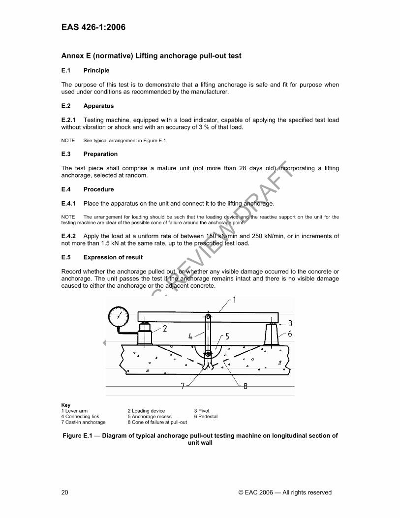
Annex E (normative) Lifting anchorage pull-out test E.1 Principle The purpose of this test is to demonstrate that a lifting anchorage is safe and fit for purpose when used under conditions as recommended by the manufacturer. E.2 Apparatus E.2.1 Testing machine, equipped with a load indicator, capable of applying the specified test load without vibration or shock and with an accuracy of 3 % of that load. NOTE See typical arrangement in Figure E.1. E.3 Preparation The test piece shall comprise a mature unit (not more than 28 days old) incorporating a lifting anchorage, selected at random. E.4 Procedure E.4.1 Place the apparatus on the unit and connect it to the lifting anchorage. NOTE The arrangement for loading should be such that the loading device and the reactive support on the unit for the testing machine are clear of the possible cone of failure around the anchorage point. E.4.2 Apply the load at a uniform rate of between 150 kN/min and 250 kN/min, or in increments of not more than 1.5 kN at the same rate, up to the prescribed test load. E.5 Expression of result Record whether the anchorage pulled out, or whether any visible damage occurred to the concrete or anchorage. The unit passes the test if the anchorage remains intact and there is no visible damage caused to either the anchorage or the adjacent concrete.
Key 1 Lever arm 2 Loading device 3 Pivot 4 Connecting link 5 Anchorage recess 6 Pedestal 7 Cast-in anchorage 8 Cone of failure at pull-out
Figure E.1 — Diagram of typical anchorage pull-out testing machine on longitudinal section of
unit wall

PUBLIC R
EVIEW DRAFT
EAS 426-1:2006
© EAC 2006 — All rights reserved 21
Bibliography CD/K/61-4/2004, Precast concrete pipes, fittings and ancillary products — Part 4: Specification for unreinforced and reinforced pipes and fittings with flexible joints EAS 426-120:1989, Precast concrete pipes, fittings and ancillary products — Part 120: Specification for reinforced jacking pipes with flexible joints BS 8110-1:1997, Structural use of concrete — Part 1: Code of practice for design and construction BS 8110-2:1985, Structural use of concrete — Part 2: Code of practice for special circumstances EAS 417-1, Concrete — Part 1: Method of specifying and guidance for the specifier EAS 417-2, Concrete — Part 2: Specification for constituent materials and concrete EN 752-2:1997, Drain and sewer systems outside buildings — Part 2: Performance requirements EN 752-3:1997, Drain and sewer systems outside buildings — Part 3: Planning EN 752-4:1998, Drain and sewer systems outside buildings — Part 4: Hydraulic design and environmental considerations EN 1295-1:1998, Structural design of buried pipelines under various conditions of loading — Part 1: General requirements BS EN 1610:1998, Construction and testing of drains and sewers

PUBLIC R
EVIEW DRAFT

PUBLIC R
EVIEW DRAFT
EAS 426-1:2006
© EAC 2006 — All rights reserved