Embed Size (px)
Citation preview
PUBLIC R
EVIEW DRAFT
DRAFT UGANDA STANDARD
DUS EAS 426-4
First Edition 2016-mm-dd
Reference number DUS EAS 426-4: 2006
© UNBS 2016
Concrete pipes and ancillary concrete products — Part 4: Specification for pre-stressed non-pressure pipes and fittings with flexible joints

PUBLIC R
EVIEW DRAFT
DUS EAS 426-4:2006
ii © UNBS 2016 - All rights reserved
Compliance with this standard does not, of itself confer immunity from legal obligations
A Uganda Standard does not purport to include all necessary provisions of a contract. Users are responsible for its correct application
© UNBS 2016
All rights reserved. Unless otherwise specified, no part of this publication may be reproduced or utilised in any form or by any means, electronic or mechanical, including photocopying and microfilm, without prior written permission from UNBS.
Requests for permission to reproduce this document should be addressed to
The Executive Director Uganda National Bureau of Standards P.O. Box 6329 Kampala Uganda Tel: 256 417 333 250/1/2/3 Fax: 256 414 286 123 E-mail: [email protected] Web: www.unbs.go.ug

PUBLIC R
EVIEW DRAFT
DUS EAS 426-4:2006
© UNBS 2016 - All rights reserved iii
National foreword
Uganda National Bureau of Standards (UNBS) is a parastatal under the Ministry of Trade, Industry and Cooperatives established under Cap 327, of the Laws of Uganda, as amended. UNBS is mandated to co-ordinate the elaboration of standards and is
(a) a member of International Organisation for Standardisation (ISO) and
(b) a contact point for the WHO/FAO Codex Alimentarius Commission on Food Standards, and
(c) the National Enquiry Point on TBT Agreement of the World Trade Organisation (WTO).
The work of preparing Uganda Standards is carried out through Technical Committees. A Technical Committee is established to deliberate on standards in a given field or area and consists of representatives of consumers, traders, academicians, manufacturers, government and other stakeholders.
Draft Uganda Standards adopted by the Technical Committee are widely circulated to stakeholders and the general public for comments. The committee reviews the comments before recommending the draft standards for approval and declaration as Uganda Standards by the National Standards Council.
This Draft Uganda Standard, DUS EAS 426-4: 2006, Concrete pipes and ancillary concrete products — Part 4: Specification for pre-stressed non-pressure pipes and fittings with flexible joints, is identical with and has been reproduced from an East African Standard, EAS 426-4: 2006, Concrete pipes and ancillary concrete products — Part 4: Specification for pre-stressed non-pressure pipes and fittings with flexible joints, and is being proposed for adoption as a Uganda Standard.
This standard was developed by the Building and civil engineering Standards Technical Committee (UNBS/TC 3).
Wherever the words, “East African Standard" appear, they should be replaced by "Uganda Standard."

PUBLIC R
EVIEW DRAFT
EAS 426-4:2006
ICS 91.140.80
HS 6810.20.00 HS 6810.91.00
© EAC 2006 First Edition 2006
EAST AFRICAN STANDARD
Concrete pipes and ancillary concrete products — Part 4: Specification for prestressed non-pressure pipes and fittings with flexible joints
EAST AFRICAN COMMUNITY

PUBLIC R
EVIEW DRAFT
EAS 426-4:2006
ii © EAC 2006 — All rights reserved
Table of contents 1 Scope ..........................................................................................................................................1 2 Normative references...................................................................................................................1 3 Terms and definitions...................................................................................................................2 4 Symbols.......................................................................................................................................4 5 General requirements ..................................................................................................................5
5.1 Application...........................................................................................................................5 5.2 Prestressing wire.................................................................................................................5 5.4 Finish (4.3.2) .......................................................................................................................7 5.5 Geometrical characteristics (4.3.3) ......................................................................................7 5.6 Durability of joints (4.3.4.2)..................................................................................................8 5.7 Crushing strength (4.3.5).....................................................................................................8 5.8 Bends (4.3.3.3)....................................................................................................................8
6 Special requirements ...................................................................................................................9 6.1 Core pipe.............................................................................................................................9 6.2 Circumferential prestressing.............................................................................................. 10 6.3 Cover coat......................................................................................................................... 10
7 Conformity evaluation ................................................................................................................ 11 7.1 Application......................................................................................................................... 11 7.2 Prestressing wire............................................................................................................... 11 7.3 Water absorption (6.7)....................................................................................................... 12 7.4 Geometrical characteristics ............................................................................................... 12 7.5 Crushing strength (Annex C) ............................................................................................. 12 7.6 Prestressing and reinforcement (6.3) ................................................................................ 12 7.7 Process control cubes or cylinders (7.2.3 and G.9) ........................................................... 12 7.8 Cover coat thickness ......................................................................................................... 13 7.9 Cover coat bond................................................................................................................ 13
8 Marking...................................................................................................................................... 13 Annex A (informative) Information to be supplied in an enquiry or order ............................................ 14 Annex B (informative) Standards relevant to CD/K/60/2004............................................................... 15 Annex C (normative) Supplementary provisions for prestressing wire................................................ 16 Annex D (normative) Surface finish tests............................................................................................ 23 Annex E (normative) Dimensional tests.............................................................................................. 25

PUBLIC R
EVIEW DRAFT
EAS 426-4:2006
© EAC 2006 — All rights reserved iii
Foreword Development of the East African Standards has been necessitated by the need for harmonizing requirements governing quality of products and services in East Africa. It is envisaged that through harmonized standardization, trade barriers which are encountered when goods and services are exchanged within the Community will be removed. In order to achieve this objective, the Partner States in the Community through their National Bureaux of Standards, have established an East African Standards Committee.
The Committee is composed of representatives of the National Standards Bodies in Partner States, together with the representatives from the private sectors and consumer organizations. Draft East African Standards are circulated to stakeholders through the National Standards Bodies in the Partner States. The comments received are discussed and incorporated before finalization of standards, in accordance with the procedures of the Community.
East African Standards are subject to review, to keep pace with technological advances. Users of the East African Standards are therefore expected to ensure that they always have the latest versions of the standards they are implementing.
© East African Community 2006 — All rights reserved*
East African Community
P O Box 1096
Arusha
Tanzania
Tel: 255 27 2504253/8
Fax: 255-27-2504481/2504255
E-Mail: [email protected]
Web: www.each.org
[Based on BS 5911-5:2004]
*
© 2005 EAC — All rights of exploitation in any form and by any means reserved worldwide for EAC Partner States’ NSBs.

PUBLIC R
EVIEW DRAFT

PUBLIC R
EVIEW DRAFT
EAS 426-4:2006
© EAC 2006 — All rights reserved 1
Concrete pipes and ancillary concrete products — Part 5: Specification for prestressed non-pressure pipes and fittings with flexible joints
1 Scope This part of BS 5911 specifies requirements and describes test methods for prestressed concrete non-pressure circular pipes and fittings with flexible joints (with seals either integrated in the units or supplied separately) and nominal sizes not exceeding DN 3200, for which the main intended use is the conveyance of sewage, rainwater and surface water under gravity or occasionally at low head of pressure, in pipelines that are generally buried. BS EN 752-2, BS EN 752-3 and BS EN 752-4, BS EN 1295-1 and BS EN 1610 deal with the planning, design, installation and testing of drains and sewers.
2 Normative references The following referenced documents are indispensable for the application of this document. For dated references, only the edition cited applies. For undated references, the latest edition of the referenced document (including any amendments) applies. BS 146, Specification for blastfurnace cements with strength properties outside the scope of EAS 18-1. BS 3123, Specification for spring calipers and spring dividers. BS 3892-1, Pulverized-fuel ash — Part 1: Specification for pulverized-fuel ash for use with Portland cement. BS 4027, Specification for sulfate-resisting Portland cement. BS 4035, Specification for linear measuring instruments for use on building and civil engineering constructional works — Steel measuring tapes, steel bands and retractable steel pocket rules. BS 4449, Specification for carbon steel bars for the reinforcement of concrete. BS 4482, Specification for cold reduced steel wire for the reinforcement of concrete. BS 4483, Specification for steel fabric for the reinforcement of concrete. BS 4484-1, Specification for measuring instruments for constructional works — Part 1: Metric graduation and figuring of instruments for linear measurement. BS 5204-1, Specification for straightedges — Part 1: Cast iron straightedges (bow-shaped and I-section). BS 5204-2, Specification for straightedges — Part 2: Steel or granite straightedges of rectangular section. BS 5896:1980, Specification for high tensile steel wire and strand for the prestressing of concrete. BS 6699, Specification for ground granulated blastfurnace slag for use with Portland cement.
EAST AFRICAN STANDARD
PUBLIC R
EVIEW DRAFT
EAS 426-4:2006
2 © EAC 2006 — All rights reserved
EAS 18-1, Cement — Part 1: Composition, specifications and conformity criteria for common cements. BS EN 206-1:2000, Concrete — Part 1: Specification, performance, production and conformity. BS EN 681-1, Elastomeric seals — Material requirements for pipe joint seals used in water and drainage applications — Part 1: Vulcanized rubber. BS EN 934-2, Admixtures for concrete, mortar and grout — Part 2: Concrete admixtures — Definitions, requirements, conformity, marking and labelling. BS EN 1008, Mixing water for concrete — Specification for sampling, testing and assessing the suitability of water, including water recovered from processes in the concrete industry, as mixing water for concrete. BS EN 1916, Concrete pipes and fittings, unreinforced, steel fibre and reinforced. BS EN 12620:2002, Aggregates for concrete. BS EN 12390-2, Testing hardened concrete — Part 2: Making and curing specimens for strength tests. BS EN 12390-3, Testing hardened concrete — Part 3: Testing hardened concrete. Compressive strength of test specimens. 3 Terms and definitions For the purposes of this part of BS 5911, the terms and definitions given in BS EN 1916 and the following apply. 3.1 cementitious content amount of cement plus any pozzolanic or latent hydraulic addition in the concrete mix 3.2 core pipe pipe that is structurally reinforced with non-tensioned steel, or longitudinally prestressed with pretensioned high tensile steel wire, or a combination of both, embedded in the concrete (see Figure 1) 3.3 cover coat layer of cement/fine aggregate mortar applied to the outside of a circumferentially prestressed core pipe (see Figure 1) 3.4 manufacturing diameter diameter of a unit that a manufacturer seeks to achieve

PUBLIC R
EVIEW DRAFT
EAS 426-4:2006
© EAC 2006 — All rights reserved 3
Key 1 High tensile steel wires for longitudinal prestressing, or mild steel reinforcement cage 4 Longitudinal wire anchor 2 Cover coat 5 Elastomeric seal 3 High tensile steel wires for circumferential prestressing 6 Concrete core
Figure 1 — Typical section of a prestressed concrete pipe with a spigot and socket joint
3.5 prestressed concrete pipe core pipe that is circumferentially prestressed to withstand design loads for the installed condition and is protected by a cover coat NOTE A typical section through a prestressed concrete pipe with spigot and socket joint is shown in Figure 1. 3.6 slurry coat coat of cement and water sprayed over a core pipe and circumferential prestressing wire before application of the cover coat 3.7 splay pipe prestressed concrete pipe formed with either the socket or the spigot off-set at an angle to its longitudinal axis (see Figure 2)

PUBLIC R
EVIEW DRAFT
EAS 426-4:2006
4 © EAC 2006 — All rights reserved
b) Typical splay pipe (spigot) Key 1 Effective length of splay pipe 2 Nominal angle
Figure 2 — Typical splay pipes
4 Symbols The meanings of symbols used in this part of BS 5911 shall be as given in Table 1, together with those in CD/K/60/2004, Table 2.
Table 1 — Symbols
Symbol Meaning Unit Reference
wD Nominal diameter of prestressing wire mm C.3.2 and C.3.3
sh Height of studs on straightness gauge mm E.3.2.1
'l Internal barrel length minus 0.1 m m E.3.2.1

PUBLIC R
EVIEW DRAFT
EAS 426-4:2006
© EAC 2006 — All rights reserved 5
5 General requirements NOTE The numbers in parentheses after subclause headings are the corresponding subclause numbers in CD/K/60/2004.
5.1 Application
Except where otherwise prescribed, the requirements of this part of BS 5911 shall be in addition to those specified in BS EN 1916 for reinforced concrete pipes and, for the purposes of the latter, the reference specifications shall be those listed in Annex B of this standard. 5.2 Prestressing wire
Wire for prestressing a core pipe shall be cold-drawn high tensile steel wire, straightened and stress relieved, conforming to BS 5896:1980, Section Two and Annex C of this standard. 5.3 Concrete (4.2) 5.3.1 Types of cement
The cement (see CD/K/60/2004, 4.1) shall either:
a) be factory-produced by the cement manufacturer and conform to one of the following standards as appropriate:
Type of cement Standard CEM I EAS 18-1 CEM II/B-V EAS 18-1 BIII/B BS 146 sulfate-resisting Portland BS 4027; or
b) consist of a combination of cement conforming to CEM I as specified in EAS 18-1 and an addition in the form of ground granulated blastfurnace slag (ggbs) or pulverized-fuel ash (pfa) in the proportions specified in 5.3.2.1, to be included as part of the concrete mix by simultaneously combining them with the other concrete materials at the concrete mixer.
In all cases where combinations of cement conforming to CEM I as specified in EAS 18-1 and ggbs or pfa are used, the relevant proportion of ggbs or pfa shall be fully documented in the production records. 5.3.2 Cementitious content (4.2.4) 5.3.2.1 Core pipe
The fully compacted concrete shall have a minimum cementitious content of not less than the relevant amount shown in Table 2. The composition/specification of cement groups shall be as shown in Table 3. 5.3.2.2 Slurry coat
The slurry coat shall consist of one part by mass of water mixed with 1.5 to 1.6 parts by mass of Portland cement. 5.3.2.3 Cover coat
The cover coat mortar shall consist of one part by mass of Portland cement mixed with not more than three parts by mass of fine aggregate conforming to BS EN 12620 designation 0/4 (CP), category GF85 and have a water/cement ratio not greater than 0.35. 5.3.2.4 Cement compatibility
Cement conforming to BS 4027 shall not be used with any other cement within the same unit.
5.3.3 Chloride content (4.2.5)
The calculated chloride ion content of the concrete, mortar or slurry mixes shall not exceed 0.1 % by mass of their respective cementitious contents.
PUBLIC R
EVIEW DRAFT
EAS 426-4:2006
6 © EAC 2006 — All rights reserved
Table 2 — Cementitious content
a
Classb Aggregate carbonate rangec
Cement or combination group
Minimum cement or combination content kg/m3
Maximum w/c ratio
DC-2 A, B, C 1, 2, 3 340 0.45 A 2a 400 0.40 A 2b, 3 380 0.45
DC-3
B, C 2, 3 340 0.45 DC-3* B 2, 3 380 0.45 DC-3* * C 2, 3 380 0.45
A 2a 400 0.35 A 2b, 3 400 0.40 A 2, 3 380 0.33 B, C 2, 3 380 0.45
DC-4
B, C 2, 3 360 0.40 B 2, 3 380 0.33 DC-4* B 2, 3 400 0.40 C 2, 3 380 0.33 DC-4* * C 2, 3 400 0.40 A 2b, 3 380 0.33 A 2b, 3 400 0.40 B 3 400 0.40 B, C 3 360 0.40
DC-4m
B, C 3 380 0.45 DC-4m* B 3 380 0.33
C 3 380 0.33 DC-4m* * C 3 400 0.40
a The table is consistent with the provisions of BS 8500-1:2002 and BRE Special Digest 1 [1] insofar as they relate to precast concrete pipeline systems, except that the maximum water/cement (w/c) ratio is limited to 0.45 in accordance with CD/K/60/2004, 4.2.3.2. b The class designations are those for design chemical class (DC-class) in cd/k/58-1/2004, Table A.15. Where there is more than one option in a class the choice is at the manufacturer’s discretion. c See BRE Special Digest 1 - Part 4, Table 4.
Table 3 — Cement or combination groupsa
Type (see 5.2.1.1) Designation Standard Grouping with
respect to sulfate resistance
Portland cement CEM I EAS 18-1 1 Portland fly ash cements CEM II/B-Vb EAS 18-1 2ac Sulfate-resisting Portland cement SRPC BS 4027 3 Blastfurnace slag cementse BIII/Bd BS 146 2be Combinations conforming to CD/K/58-2/2004, Annex A manufactured in the concrete mixer from Portland cement and pfa or ggbs:
CEM I cement conforming to EAS 18-1 with a mass fraction of 6 % to 20 % of combination of pfa conforming to BS 3892-1
CIIA-V CD/K/58-2/2004
1
CEM I cement conforming to EAS 18-1 with a mass fraction of 21 % to 35 % of combination of pfa conforming to BS 3892-1
CIIB-Vb CD/K/58-2/2004
2ac
CEM I cement conforming to EAS 18-1 with a mass fraction of 36 % to 55 % of combination of pfa conforming to BS 3892-1
CIVB-Vb CD/K/58-2/2004
2af
CEM I cement conforming to EAS 18-1 with a mass fraction of 6 % to 35 % of combination of ggbs conforming to BS 6699
CII-Sg CD/K/58-2/2004
1
CEM I cement conforming to EAS 18-1 with a mass fraction of 36 % to 65 % of combination of ggbs conforming to BS 6699
CIIIA CD/K/58-2/2004
1
CEM I cement conforming to EAS 18-1 with a mass fraction of 66 % to 80 %e of combination of ggbs conforming to BS 6699
CIIIBd CD/K/58-2/2004
2be
a The table is consistent with BS 8500-1:2002, Table A.17 and CD/K/58-2/2004, Table 1. b Where the proportions for sulfate resistance are required, i.e. not less than 25 % and not more than 40 % pfa, add to the abbreviation “+SR”. c Provided the pfa content is a mass fraction of not less than 25 % of cement or combination. Where it is less than 25 %, the cement of combination falls within group 1. d Where the proportions for sulfate resistance are required (see e), add to the abbreviation “+SR”. e Where the alumina content of the slag exceeds 14 %, the tricalcium aluminate content of the Portland cement fraction should not exceed 10 %. Where this is not the case, the grouping with respect to sulfate resistance is “1”. f Provided the pfa content is a mass fraction of not more than 40 % of cement or combination. Where it exceeds 40 %, no guidance is provided. g Where necessary, this class can be subdivided into CIIA-S (6 % to 20 % ggbs) and CIIB-S (20 % to 35 % ggbs).

PUBLIC R
EVIEW DRAFT
EAS 426-4:2006
© EAC 2006 — All rights reserved 7
5.4 Finish (4.3.2) 5.4.1 Surface evenness When tested in accordance with D.1, the internal surface of a unit shall not have irregularities that cause the central portion of the gauge to touch the unit. 5.4.2 Surface voids When tested in accordance with D.2 surfaces of units shall be free from voids that permit diametrically opposite points of the rim of the gauge to touch the surface of the unit simultaneously. Units exhibiting any surface void greater than 12 mm deep shall be deemed not to conform to this part of BS 5911. NOTE Voids up to and including 12 mm deep may be made good by the manufacturer — see CD/K/60/2004, 4.3.2. 5.4.3 Surface cracking In addition to the requirements of CD/K/60/2004, 4.3.2 and 6.3.4 of this part of BS 5911, the surface width of any circumferential crack in a core pipe due to discontinuity of prestress at the spigot end shall not exceed 0.1 mm.
5.5 Geometrical characteristics (4.3.3) 5.5.1 General Subject to the requirements of this clause, the internal diameter and core pipe wall thickness of units, and the configuration of splay pipes and bends, shall conform to those stated in the factory documents. 5.5.2 Nominal sizes NOTE Nominal size is defined in CD/K/60/2004, 3.1.16 as a numerical designation of the size of a unit, which is a convenient integer approximately equal to the manufacturing dimension in millimetres; for a circular unit it is the internal diameter (DN). The nominal sizes of units shall be those given in Table 4. 5.5.3 Internal manufacturing diameters The manufacturer shall make available, at the enquiry stage, information on the internal manufacturing diameters of units that can be supplied (see Annex A). The internal manufacturing diameters of units shall be not outside the limits given in Table 4. 5.5.4 Dimensional tolerances 5.5.4.1 Tolerances on internal diameter The tolerance on the internal manufactured diameter of a unit shall be ±(3 + 0.005DN) mm, limited to ±15 mm (see Table 4). No individual measurement, measured in accordance with E.1 shall be outside the specified limits. 5.5.4.2 Tolerances on core pipe wall thickness Any value of core pipe wall thickness measured in accordance with E.2 shall be not less than the value stated in the factory documents.

PUBLIC R
EVIEW DRAFT
EAS 426-4:2006
8 © EAC 2006 — All rights reserved
5.5.4.3 Deviation from internal straightness When measured in accordance with E.3, both ends of the gauge shall not make contact with the internal surface of a straight unit when using Edge X and the two studs shall be in contact simultaneously with that surface when using Edge Y. Table 4 — Nominal sizes, internal manufacturing diameters and tolerances of units
Limits of internal manufacturing diameter
mm
Tolerance on internal manufactured diameter
mm
Nominal size
DN Minimum Maximum Internal
450 440 460 ±5 500 490 525 ±6 600 580 610 ±6 700 675 720 ±7 800 770 825 ±7 900 875 950 ±8 1000 980 1 070 ±8 1200 1 180 1 220 ±9 1400 1 350 1 420 ±10 1500 1 470 1 530 ±11 1600 1 580 1 675 ±11 1800 1 780 1 830 ±12 2000 1 950 2 135 ±13 2200 2 170 2 250 ±14 2500 2 375 2 550 ±15 2800 2 680 2 850 ±15 3000 2 965 3 050 ±15 3200 3165 3250 ±15 NOTE Classic sizes, denoted by an asterisk, will be phased out if called for by further harmonization.
5.5.4.4 Squareness of ends Units other than splay pipes shall be capable of being jointed in any orientation with their axes coincident within the deflection limit specified in CD/K/60/2004, E.5.2. NOTE 1 Squareness of ends of units is significant only to the extent that it relates to the performance of the joint assembly. NOTE 2 Information on the splay angles that can be supplied for splay pipes should be given to the purchaser on request (see Annex A).
5.6 Durability of joints (4.3.4.2) The durability of joints shall be demonstrated in accordance with CD/K/60/2004, 4.3.4.2 Method 1.
5.7 Crushing strength (4.3.5) NOTE Strength class is defined in CD/K/60/2004, 3.1.19 as the minimum crushing load in kilonewtons per metre, divided by one thousandth of a unit's nominal size (DN). Units shall be strength class 120 with corresponding minimum crushing loads in accordance with Table 5. Units of other crushing strength shall be permitted only if their special strength class is separated by at least 20 % of the next lower value and that they conform to BS EN 1916 and this part of BS 5911 in all other respects. Minimum crushing loads corresponding to special strength classes shall be rounded up to the nearest kilonewton per metre (kN/m).
5.8 Bends (4.3.3.3) Bends shall be fabricated from cut lengths of pipe conforming to this part of BS 5911.

PUBLIC R
EVIEW DRAFT
EAS 426-4:2006
© EAC 2006 — All rights reserved 9
For bends having subtended angles ! greater than 70°, the radius r as shown in CD/K/60/2004, Figure 3 shall be a minimum of 0.7DN mm. NOTE Typical angles ! are 11° 15´, 22° 30´ and 45°. Table 5 — Minimum crushing loads for strength class 120 units
Nominal size DN
Minimum crushing load, Fn kN/m
450* 54 500 60 600 72 700 84 800 96 900* 108 1000 120 1200 144 1400 168 1500* 180 1600 192 1800 216 2000 240 2200 264 2500 300 2800 336 3000 360 3200 384 NOTE 1 Classic sizes, denoted by an asterisk will be phased out if called for by further European harmonization. NOTE 2 BS EN 1295-1:1998, Table NA.5 recommends that the minimum value of safety factor for the structural design of reinforced pipelines should be increased from the normal 1.25 to 1.5 if, as is the case of CD/K/60/2004, the proof load is 67 % of the minimum crushing load. The recommendation is equally valid for prestressed non-pressure concrete pipelines.
6 Special requirements NOTE The numbers or letters in brackets after subclause headings are the corresponding subclause numbers or Annex designations in CD/K/60/2004.
6.1 Core pipe 6.1.1 Prestressing or reinforcement 6.1.1.1 General At the manufacturer's discretion a core pipe shall either be longitudinally prestressed in accordance with 6.1.1.2, or reinforced with non-tensioned steel in accordance with 6.1.1.3. 6.1.1.2 Longitudinal prestressing The core pipe shall be longitudinally prestressed throughout its length (including the socket) by means of high tensile steel wires, which shall be provided with permanent anchorages embedded in the concrete within the joint portion at each end. The longitudinal prestress shall be sufficient to prevent tensile cracks developing in the core pipe due to the combined effects of circumferential prestressing and bending due to beam loading. The longitudinal wires shall be stressed to the design tension, taking into account the yield or slip of the temporary anchorages on the pipe moulds, and the tension shall be maintained whilst curing the concrete. The tensioned wires shall not be released until the concrete in the core pipe has attained a characteristic compressive strength of 27 MPa, as demonstrated by process control cubes or cylinders (see 7.7), the choice being at the manufacturer's discretion.

PUBLIC R
EVIEW DRAFT
EAS 426-4:2006
10 © EAC 2006 — All rights reserved
6.1.1.3 Reinforcement As an alternative to longitudinal prestressing in accordance with 6.1.1.2 (see 6.1.1.1), it is permissible for the core pipe to be reinforced with non-tensioned steel in accordance with CD/K/60/2004, 5.2.1, in order to prevent tensile cracks developing due to the combined effects of the circumferential prestressing and bending due to beam loading. 6.1.2 Concrete cover (5.2.2) The minimum concrete cover at the end faces of a core pipe shall be 12 mm; for all other surfaces of the core pipe it shall be 15 mm or the relevant nominal maximum size of aggregate stated in the factory documents, whichever is the larger. The holes at the longitudinal wire anchors in the spigot and socket faces shall be plugged with mortar conforming to 5.3.2.3, to ensure a watertight seal to the steel anchors. NOTE 1 Given the inspection procedures specified in this part of BS 5911 and the maximum permitted stabilized surface crack width specified in CD/K/60/2004, 5.2.3 the value of minimum concrete cover is consistent with the serviceability conditions specified in CD/K/60/2004,4.3.8. Taken together, these factors are also consistent with the crack control provisions given in BS 8110-1 and BS 8110-2. NOTE 2 Units conveying sea water, industrial waste, etc. and those to be installed in more aggressive serviceability conditions than those specified in CD/K/60/2004, 4.3.8 might need additional concrete cover. The advice of the pipe manufacturer should be sought in such a situation. 6.2 Circumferential prestressing 6.2.1 General Circumferential prestressing shall not take place until the concrete in a core pipe has reached sufficient compressive strength to resist without damage the forces acting upon it, which shall be not less than a minimum characteristic value of 35 MPa as demonstrated by process control cubes or cylinders (see 7.7), the choice being at the manufacturer's discretion. The compressive stress induced in a core pipe during prestressing shall not exceed 55 % of the characteristic compressive strength of the concrete in the core pipe at that time. The mean tension in the circumferential prestressing wire shall be at least the design tension. Normal fluctuations in tension shall not deviate by more than 10 %, nor shall more than 5 % of the windings have instantaneous fluctuations exceeding the 10 % deviation. 6.2.2 Winding
Methods and equipment for applying the circumferential prestressing wire shall be:
a) such that the wire is wound around the core pipe in a helical form at the design spacing stated in the factory documents; and
b) capable of controlling and indicating the tension. 6.2.3 Spacing
The clear distance between circumferential prestressing wire shall be not less than 5 mm. 6.2.4 Splicing
The design of any splice to be made in prestressing wire shall be recorded in the factory documents and the tensile strength of all splices shall be not less than that of the wire itself.
6.3 Cover coat 6.3.1 Preparation of external surface To obtain a satisfactory bond, care shall be taken to ensure that the external surface of a core pipe is damp immediately before application of the slurry and cover coats.

PUBLIC R
EVIEW DRAFT
EAS 426-4:2006
© EAC 2006 — All rights reserved 11
6.3.2 Application of slurry and cover coats The slurry coat shall be sprayed over a core pipe and circumferential prestressing wires immediately before application of the cover coat which, premixed with water, shall then be mechanically driven at high velocity against the external surface of the core pipe and wires, producing a dense coating having a thickness of not less than 20 mm over all wires. For multiple layers of windings and cover coating, the final cover coat shall provide the 20 mm minimum cover. Pneumatic processes in which the mixing of ingredients is carried out at the nozzle or gun shall not be used. 6.3.3 Cover coat bond There shall be no debonding of the cover coat from a core pipe or circumferential prestressing wires in a finished product. If, on inspection, debonding is found to have taken place (see 7.9), the cover coat shall be removed from the defective area at least 25 mm around the area of debonding. A slurry coat as specified in 5.3.2.2 shall then be applied to the exposed core pipe and circumferential wire immediately before the cover coat repair is applied. The cover coat shall be replaced in accordance with 6.3.2. 6.3.4 Crushing strength The requirement in CD/K/60/2004, 5.2.3 for a maximum stabilized surface crack width of 0.30 mm when tested in accordance with CD/K/60/2004, 6.4 shall be amended to 0.20 mm for the purposes of this part of BS 5911. There shall be no cracks in the cover coat other than those permitted by 5.4.3 of this part of BS 5911. The requirement in CD/K/60/2004, C.4.4 for the load to be increased to the ultimate (collapse) load Fu shall be deemed to be met if the applied load has reached 1.10 times the minimum crushing load Fn without causing the pipe to collapse. NOTE For prestressed concrete non-pressure pipes, especially in the larger sizes, it is often impracticable for the apparatus to test the pipe to collapse. 6.3.5 Conformity of proof (crack) load tested pipes Pipes tested only to proof (crack) load in accordance with CD/K/60/2004, 6.4 and meeting the requirements of 6.3.4 of this part of BS 5911 shall be deemed to conform to this standard.
7 Conformity evaluation
7.1 Application The conformity evaluation requirements of BS EN 1916 shall apply to this part of BS 5911, supplemented or qualified by the following sampling procedures.
7.2 Prestressing wire 7.2.1 Sampling procedures After an initial type test in each case, routine inspection of elongation, reverse torsion and resistance to hydrogen embrittlement shall be carried out on the basis of batches comprising each consignment of prestressing wire or, if the consignment embraces more than one casting of constituent metal, each part of the consignment relevant to a separate casting. For the elongation and reverse torsion tests, three samples shall be taken in each case from three different spools or coils of wire. For the resistance to hydrogen embrittlement test the six test cylinders shall be wound using wire from at least three different spools or coils.

PUBLIC R
EVIEW DRAFT
EAS 426-4:2006
12 © EAC 2006 — All rights reserved
7.2.2 Acceptance criteria for resistance to hydrogen embrittlement The acceptance criteria for the resistance of the prestressing wire to hydrogen embrittlement shall be as follows: a) if the breaking time (see C.5) for each of the six test cylinders is greater than 90 min, the batch
shall be accepted; b) if the breaking time for one or more cylinders is less than 90 min, the test shall be repeated using
six other cylinders; c) if the mean of the breaking times for the three worst results in each of the two series in b) is
greater than 90 min, the batch shall be accepted; nevertheless, if in each of the two series the breaking time for one or more cylinders is less than 60 min, the batch shall be rejected;
d) if the mean of the breaking times for the three worst results in each of the two series in b) is less
than 90 min, the batch shall be rejected. 7.3 Water absorption (6.7) Samples for the purposes of CD/K/60/2004, 6.7 shall be cut from a hardened core pipe.
7.4 Geometrical characteristics Sampling procedures to evaluate the conformity of internal diameter, core pipe wall thickness and internal straightness to 5.5.4.1, 5.5.4.2 and 5.5.4.3 respectively shall be in accordance with those for “Geometrical characteristics — units” in CD/K/60/2004, Table H.1.
7.5 Crushing strength (Annex C) For the purposes of this part of BS 5911, references in CD/K/60/2004, Annex I to the ultimate (collapse) load Fu in connection with reinforced concrete pipes shall be taken as references to 1.10 times the minimum crushing load Fn where such a load has not caused a pipe to collapse; “basic” level inspection of crushing strength in accordance with CD/K/60/2004, I.1.1 is not permitted.
7.6 Prestressing and reinforcement (6.3) The conformity of the core pipe longitudinal prestressing or reinforcement and the circumferential prestressing to 6.1 and 6.2 respectively shall be evaluated as for reinforcement in accordance with CD/K/60/2004, 6.1 and 6.3.
7.7 Process control cubes or cylinders (7.2.3 and G.9) NOTE The testing of cubes or cylinders is intended as a control check at critical stages of manufacture (see 6.1.1) and not as an indication of the proof load crushing strength of matured units. Process control cubes or cylinders shall be made and cured either: a) in a manner that reflects the pipe manufacturing process; or b) in accordance with BS EN 12390-2. The cubes or cylinders shall be tested in accordance with the relevant part of BS EN 12390-3, sufficient being made and tested to ensure that a core pipe has reached the required minimum characteristic compressive strength at the stages described in 6.1.1.2 and 6.2.1. If the method given in b) is adopted by the manufacturer, a conversion factor shall be applied to the results of the tests to take into account differences between the pipe manufacturing process and that used to produce the test specimens in accordance with the relevant part of BS EN 12390-2 and BS EN 12390-3.

PUBLIC R
EVIEW DRAFT
EAS 426-4:2006
© EAC 2006 — All rights reserved 13
This conversion factor shall be determined by the manufacturer by correlation tests, the results of which shall be made available for inspection. Correlation tests shall be repeated at least annually and whenever a change is made in the materials or process used to manufacture the pipes. The minimum frequency of sampling shall be in accordance with BS EN 206-1:2000, 8.2.1.
7.8 Cover coat thickness The conformity of the cover coat thickness to 6.3.2 shall be evaluated as for concrete cover in accordance with CD/K/60/2004, 6.1 and 6.3.
7.9 Cover coat bond The cover coat bond shall be evaluated for conformity to 6.3.3 by virtue of appearance and random hammer ringing checks on a sample unit. The frequency of sampling shall be not less than once every five working days. 8 Marking In addition to the requirements in CD/K/60/2004, Clause 8 (but excluding the requirement to mark EN 1916) each unit shall be marked BS 5911-5. Special strength class units (see 5.7) shall also be marked with the relevant class.

PUBLIC R
EVIEW DRAFT
EAS 426-4:2006
14 © EAC 2006 — All rights reserved
Annex A (informative) Information to be supplied in an enquiry or order The following particulars cover essential details required by the manufacturer so that an enquiry or order may be fully understood: Reference in: CD/K/60/2004 CD/K/61-4/2004 a) quantity and nominal size(s) of units ― 5.5.1 b) any special strength class of units 4.3.5 5.7 c) design chemical class (DC-class) of concrete in units 4.3.8 5.3.2.1 d) if additional concrete cover is required 4.3.8 and 5.2.2 6.1.2 e) splay angles and whether at the spigot or socket end of splay pipes
5.3.1 ―
f) dimensions and materials of inlets or branch pipes for junctions
5.4 ―
g) if the products are to be fully covered by a third party certification scheme
7.1 Foreword

PUBLIC R
EVIEW DRAFT
EAS 426-4:2006
© EAC 2006 — All rights reserved 15
Annex B (informative) Standards relevant to CD/K/60/2004 The reference specifications prescribed in 5.1 for materials are listed in Table B.1. Table B.1 — British Standards relevant to CD/K/60/2004
Reference in CD/K/60/2004 Relevant Standard
Subclause number Material/Characteristic
EAS 18-1 BS 146
4.1 Cements
BS 4027 4.1 Aggregates BS EN 12620 4.1 Mixing water BS EN 1008a) 4.1 Admixtures BS EN 934-2
BS 3892-1 4.1 Additions BS 6699 BS 4449 BS 4482
4.1 Reinforcing steel b)
BS 4483 4.1.2 and 4.3.3.2 Joint seals BS EN 681-1 a) BS EN 1008:2002, 3.1 specifies that potable water does not need testing prestressing wire, see 5.2 b) For prestressing wire, see 5.2.

PUBLIC R
EVIEW DRAFT
EAS 426-4:2006
16 © EAC 2006 — All rights reserved
Annex C (normative) Supplementary provisions for prestressing wire NOTE This Annex is consistent with BS EN 642:1995, Annex A. C.1 Mechanical properties C.1.1 Elongation The minimum elongation of prestressing wire under the maximum load (i.e. immediately before the occurrence of necking) shall be 3 % of its original length when tested in accordance with the procedure in C.2.4.1, or 2 % excluding any necking if tested to breaking in accordance with C.2.4.2, the choice of procedure being at the manufacturer's discretion. C.1.2 Reverse torsion When tested in accordance with C.3 the prestressing wire shall not exhibit a visible crack until at least three “1 – 2 – 1” cycles (see C.3.4) of reverse torsion have been completed. C.1.3 Resistance to hydrogen embrittlement When tested in accordance with C.4 and evaluated in accordance with 7.2.2 the elapsed time before the prestressing wire breaks as a result of hydrogen embrittlement shall exceed 90 min. C.2 Elongation tests C.2.1 Principle The purpose of this test is to evaluate whether the prestressing wire conforms to either or both of the requirements in C.1.1 for minimum elongation. C.2.2 Apparatus C.2.2.1 Mechanical equipment, capable of exerting a tensile force in excess of the specified characteristic breaking load of the prestressing wire and with a means of measuring that force to an accuracy of ±3 %. C.2.3 Preparation C.2.3.1 Elongation at maximum load The test piece comprises a length of prestressing wire such that the free section to be elongated under the maximum load is greater than 200 mm. C.2.3.2 Permanent elongation The test piece comprises not less than 500 mm of prestressing wire. C.2.4 Procedure C.2.4.1 Elongation at maximum load Mark a reference length of 200 mm on the test piece then clamp it in the apparatus. Apply a tensile force to the wire and, for increasing values of load, measure the corresponding plastic elongations of the reference length. Plot the results on a load/extension graph until it shows that the maximum load has been reached. After reducing the tensile force on the wire to zero, record the plastic elongation of the reference length corresponding to the maximum load.

PUBLIC R
EVIEW DRAFT
EAS 426-4:2006
© EAC 2006 — All rights reserved 17
The elongation of the reference length is the sum of the plastic elongation at the maximum load as determined above and the elastic elongation, which is a statistical value based on certified tests by the wire supplier. Record the sum of these two elongations. C.2.4.2 Permanent elongation Make a series of reference marks 50 mm apart on the test piece then clamp it in the apparatus. Apply a tensile force to the wire and gradually increase it until the test piece breaks, then measure and record the permanent elongation of an original 100 mm reference length, chosen as being farthest from any necking of the wire. C.2.5 Expression of results C.2.5.1 Elongation at maximum load Express the summated elongation determined in accordance with C.2.4.1 as a percentage of the 200 mm reference length and record it. C.2.5.2 Permanent elongation Express the permanent elongation determined in accordance with C.2.4.2 as a percentage of the 100 mm reference length and record it. C.3 Reverse torsion test C.3.1 Principle The purpose of this test is to evaluate whether the prestressing wire conforms to the requirement in C.1.2 for reverse torsion. C.3.2 Apparatus C.3.2.1 Mechanical equipment, able to grip a test piece of prestressing wire stretched between two jaws, one of which can be rotated in either direction about the longitudinal axis of the installed test piece at a speed not exceeding one turn per 10 seconds. The distance between the jaws is equal to 50 times the nominal diameter Dw of the prestressing wire. C.3.3 Preparation The test piece comprises a length of prestressing wire not less than 70 times its nominal diameter Dw. C.3.4 Procedure Grip the test piece in the apparatus, stretched between the two jaws, and twist it one complete turn to the right about its longitudinal axis, then two turns to the left and another turn to the right, returning to the initial position. These four turns constitute a full cycle of torsion, described as “1 – 2 – 1”. Repeat the “1 – 2 – 1” procedure until the first visible crack occurs in the test piece and record the number of cycles completed. C.4 Resistance to hydrogen embrittlement test C.4.1 Principle The purpose of this test is to evaluate whether the resistance of prestressing wire to hydrogen embrittlement conforms to the requirement in C.1.3. The wire is wound at a constant tension close to the design value for working conditions onto small diameter test cylinders, which are then immersed in an acid solution whilst under cathodic polarization. This causes hydrogen to be generated and available for absorption by the wire.

PUBLIC R
EVIEW DRAFT
EAS 426-4:2006
18 © EAC 2006 — All rights reserved
C.4.2 Apparatus C.4.2.1 Six test cylinders, each consisting of a cold drawn mild steel tube placed within a suitable close-fitting and isolating hard plastic sleeve and equipped with: ⎯ a catch plate for applying a rotational movement whilst wrapping the prestressing wire around the
cylinder; ⎯ a clamping plate with bolts to secure the end of the wire after wrapping. Figure C.1 prescribes the test cylinder dimensions and details the accessories. One end of the wire to be tested is equipped with an anchoring device to hook it onto the cylinder. C.4.2.2 Electricity supply panel, equipped with regulating potentiometers and capable of supplying a direct rectified cathodic polarization current equal to 1 mA per cm2 area of immersed wire to an accuracy of ±10 %. C.4.2.3 Non-conducting acid-resistant circular tank, as described in Figure C.2 and with a platinum anode attached around its internal circumference at a height equal to half the height of test cylinder.

PUBLIC R
EVIEW DRAFT
EAS 426-4:2006
© EAC 2006 — All rights reserved 19
Dimensions in millimetres
Key 1 Anchoring device 4 Steel cylinder 2 Catch plate 5 Steel plate embedded into plastic sleeve 54 × 20 × 11 3 Suitable, hard isolating plastic sleeve 6 2 dia 10.5 holes
Figure C.1 — A test cylinder and its accessories

PUBLIC R
EVIEW DRAFT
EAS 426-4:2006
20 © EAC 2006 — All rights reserved
Dimensions in millimetres
Key 1 Self-tightening cone situated outside the solution 5 Ring hook 2 Steel wire connected to cathode 6 Circular electrode platinum 0.6 × 0.05 mm 3 Electrical wires connected to the circular electrode 7 Electrode positioning ring 4 Cylinder centring device 8 Rubber secting
Figure C.2 — Test tank and arrangement of a test cylinder in acid solution

PUBLIC R
EVIEW DRAFT
EAS 426-4:2006
© EAC 2006 — All rights reserved 21
C.4.2.4 Test solution, of hydrochloric acid (containing ½ mole of acid per litre) and “pure for analysis” characterized by the following maximum contents of impurities: — non-volatile residue < 0.0010 % — heavy metals (as lead, Pb) < 0.0002 % — iron, Fe < 0.0005 % — arsenic, As < 0.0001 % — bromine, Br < 0.0010 % — sulfate, SO4 < 0.0002 % — oxidizing agents (as chloride, Cl) < 0.0002 % — reducing agents (as sulfide, SO2) < 0.0010 % The solution, which is replaced for each test, is made from 20 litres of distilled water having a resistivity between 500 7m and 800 7m and the quantity of hydrochloric acid needed to achieve and maintain a normality between 0.48 and 0.52. C.4.3 Preparation After anchoring the end of the prestressing wire onto the first test cylinder make one helical wind, without tension so as to protect the anchoring device, then subject the wire to a winding tension equal to 75 % of its ultimate tensile strength as guaranteed by the supplier. If the guaranteed ultimate tensile strength of the wire is not known, use a winding tension equal to 70 % of its actual ultimate tensile strength. The tolerance on the winding tension shall be ±10 % of the ultimate tensile strength. Wind the wire around the cylinder at a linear speed of (40 ± 5) mm per second until seven helixes at a constant pitch are completed, then secure it with the clamping plate bolts so as to maintain the applied tension. The applied wire shall have an overall twist of at least 0.75 turns and not more than 1.5 turns. After relaxing the applied tension, cut off the loose part of the wire and make marks on both the applied wire and the cylinder so as to reveal any subsequent slipping. Fix an electrical connection (the cathode) to the anchoring device located at one end of the applied wire.
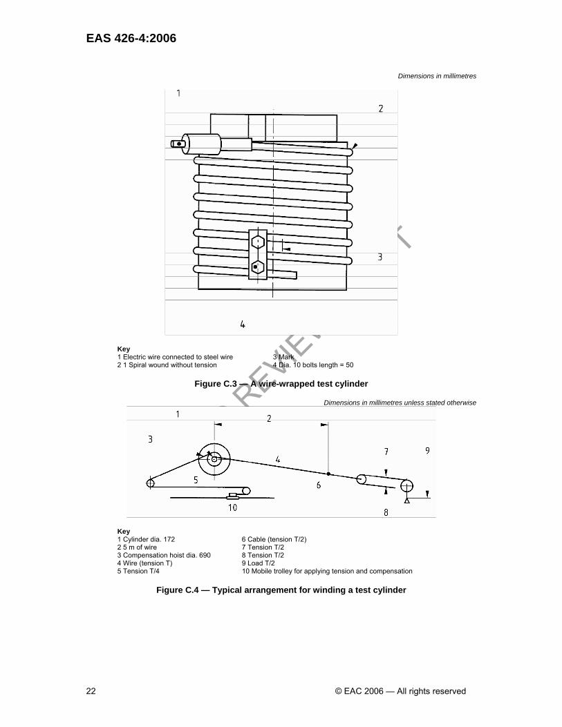
Figure C.3 describes a wire-wrapped test cylinder and Figure C.4 illustrates a typical arrangement for the winding system. On completion of the wire winding, protect the clamping plate bolts with a mastic compound to isolate the steel part from the acid solution.
Prepare the remaining five test cylinders in the same way. C.5 Procedure
Within 24 hours of winding the first test cylinder, place the acid solution in the test tank and maintain the former's temperature at (18 ± 2) °C. Partially immerse the cylinder in the solution, resting it on a rubber seating as shown in Figure C.2 and adjusting its position as necessary by means of an appropriate device.
Connect the platinum anode attached around the inside of the tank and the cathode of the wire under test to the electricity supply panel, the anode being connected at three equidistant points so that the potential is the same anywhere on its circumference. Switch on the current immediately after immersing the cylinder and thereby induce polarization as a result of the current passing between the two anodes, through the acid solution.
Record the elapsed time in minutes between switching on the current and the tensioned wire around the cylinder breaking as a result of hydrogen embrittlement (the “breaking time”). If the wire has not broken after three hours, discontinue the test and record that fact.
Repeat the procedure for the remaining five test cylinders. C.6 Expression of results The test results are expressed and recorded as the breaking time (or 180 min in the case of failure to break within 3 h) for the prestressing wire around each of the six test cylinders.
PUBLIC R
EVIEW DRAFT
EAS 426-4:2006
22 © EAC 2006 — All rights reserved
Dimensions in millimetres
Key 1 Electric wire connected to steel wire 3 Mark 2 1 Spiral wound without tension 4 Dia. 10 bolts length = 50
Figure C.3 — A wire-wrapped test cylinder
Dimensions in millimetres unless stated otherwise
Key 1 Cylinder dia. 172 6 Cable (tension T/2) 2 5 m of wire 7 Tension T/2 3 Compensation hoist dia. 690 8 Tension T/2 4 Wire (tension T) 9 Load T/2 5 Tension T/4 10 Mobile trolley for applying tension and compensation
Figure C.4 — Typical arrangement for winding a test cylinder

PUBLIC R
EVIEW DRAFT
EAS 426-4:2006
© EAC 2006 — All rights reserved 23
Annex D (normative) Surface finish tests D.1 Surface evenness test D.1.1 Principle The purpose of this test is to evaluate whether the internal surface of a unit conforms to the limiting requirement in 5.4.1 for evenness. D.1.2 Apparatus D.1.2.1 Gauge, as described in Figure D.1.
Dimensions in millimetres
Figure D.1 — Gauge for assessing surface eveness D.1.3 Procedure D.1.3.1 Place the gauge in the unit so that its axis is in the same plane as the unit's longitudinal axis. D.1.3.2 Roll the gauge around the inside of the unit, taking care to ensure that its axis remains in the same plane as the unit's longitudinal axis at all times. D.1.4 Expression of result Record whether the gauge rolled over any part of the internal surface without the central portion of the gauge contacting the unit. D.2 Surface void test D.2.1 Principle The purpose of this test is to evaluate whether any void in the surface of a unit conforms to the limiting requirement in 5.4.2. D.2.2 Apparatus D.2.2.1 Gauge, as described in Figure D.2. D.2.3 Procedure Apply the ball of the gauge to the void and record whether diametrically opposite points in the rim of the gauge simultaneously touched the surface of the unit.

PUBLIC R
EVIEW DRAFT
EAS 426-4:2006
24 © EAC 2006 — All rights reserved
Dimensions in millimetres
Key 1 Cylinder 2 Hemisphere dia. 10 ± 0.5
Figure D.2 — Gauge for assessing surface voids
PUBLIC R
EVIEW DRAFT
EAS 426-4:2006
© EAC 2006 — All rights reserved 25
Annex E (normative) Dimensional tests NOTE At the manufacturer's discretion it is permissible to use purpose-made“go/no-go” steel gauges for dimensional measurements in lieu of the apparatus specified for the tests in this Annex. E.1 Internal diameter test E.1.1 Principle The purpose of this test is to evaluate whether the internal diameter of a unit conforms to 5.5.4.1. E.1.2 Apparatus E.1.2.1 Steel measuring tape or retractable pocket rule, conforming to BS 4035 with metric graduation and figuring conforming to BS 4484-1. E.1.3 Procedure Approximately 50 mm from each end of the bore, make three measurements of the internal diameter at approximately 60° to each other. E.1.4 Expression of results Record whether each measured value of the internal diameter conforms to 5.5.4.1. E.2 Core pipe wall thickness test E.2.1 Principle The purpose of this test is to evaluate whether the wall thickness of a core pipe conforms to 5.5.4.2. E.2.2 Apparatus E.2.2.1 Outside spring caliper, conforming to BS 3123. E.2.2.2 Steel measuring tape or retractable pocket rule, conforming to BS 4035 with metric graduation and figuring conforming to BS 4484-1. E.2.3 Procedure Measure the core pipe wall thickness at approximately 50 mm from the end of the external barrel at the spigot end, at three positions equidistant around the circumference of the unit. E.2.4 Expression of results Record whether each measured value of the wall thickness conforms to 5.5.4.2. E.3 Straightness test E.3.1 Principle The purpose of this test is to evaluate whether the internal straightness of a straight unit conforms to 5.5.4.3. E.3.2 Apparatus E.3.2.1 Rigid straightedge, made into a gauge of the form and dimensions shown in Figure E.1.

PUBLIC R
EVIEW DRAFT
EAS 426-4:2006
26 © EAC 2006 — All rights reserved
E.3.3 Procedure E.3.3.1 Place the straightedge in the bore with Edge X (see Figure E.1) in contact with the unit and on a line parallel to its longitudinal axis. Hold the plane of the gauge in a radial plane and record whether both ends of the gauge, wherever so placed, were in contact with the internal surface of the unit. E.3.3.2 If both ends of the gauge were not in contact with the internal surface of the unit at both ends, reverse the gauge so that Edge Y, placed as above (see Figure E.1), is adjacent to the internal surface of the unit. E.3.4 Expression of result Record whether both ends of the gauge were in contact with the internal surface of the unit when using Edge X, and whether the two studs (see Figure E.1) touched the surface simultaneously when using Edge Y.
Dimensions in millimetres
Key 1 Edge Y 2 Edge X hs = (3.5l' ± 5 %) in mm
NOTE The studs should be detachable from the basic straightedge to facilitate checking and replacement.
Figure E.1 — Gauge for measuring deviation from internal straightness

PUBLIC R
EVIEW DRAFT
EAS 426-4:2006
© EAC 2006 — All rights reserved 27
Bibliography BS 5911-1:2002, Concrete pipes and ancillary concrete products — Part 1: Specification for unreinforced and reinforced concrete pipes (including jacking pipes) and fittings with flexible joints (complementary to CD/K/60/2004). BS 5911-100:1988, Concrete pipes and ancillary concrete products — Part 100: Specification for unreinforced and reinforced pipes and fittings with flexible joints.1) BS 8110-1:1997, Structural use of concrete — Part 1: Code of practice for design and construction. BS 8110-2:1985, Structural use of concrete — Part 1: Code of practice for special circumstances. BS 8500-1:2002, Concrete — Complementary British Standard to BS EN 206-1 — Part 1: Method of specifying and guidance for the specifier. BS 8500-2:2002, Concrete — Complementary British Standard to BS EN 206-1 — Part 2: Specification for constituent materials and concrete. BS EN 642:1995, Prestressed concrete pressure pipes, cylinder and non-cylinder, including joints, fittings and specific requirement for prestressing steel for pipes. BS EN 752-2:1997, Drain and sewer systems outside buildings — Part 2: Performance requirements. BS EN 752-3:1997, Drain and sewer systems outside buildings — Part 3: Planning. BS EN 752-4:1998, Drain and sewer systems outside buildings — Part 4: Hydraulic design and environmental considerations. BS EN 1295-1:1998, Structural design of buried pipelines under various conditions of loading — Part 1: General requirements. BS EN 1610:1998, Construction and testing of drains and sewers.

PUBLIC R
EVIEW DRAFT

PUBLIC R
EVIEW DRAFT
EAS 426-4:2006
© EAC 2006 — All rights reserved