Embed Size (px)
Citation preview

7/28/2019 DSAM-2500 Manual2 En
http://slidepdf.com/reader/full/dsam-2500-manual2-en 1/56
Acterna DSAM Product FamilyDigital Service Activation Meters
Quick-Start Guide

7/28/2019 DSAM-2500 Manual2 En
http://slidepdf.com/reader/full/dsam-2500-manual2-en 2/56

7/28/2019 DSAM-2500 Manual2 En
http://slidepdf.com/reader/full/dsam-2500-manual2-en 3/56
Acterna DSAM Product FamilyDigital Service Activation Meters
Quick-Start Guide

7/28/2019 DSAM-2500 Manual2 En
http://slidepdf.com/reader/full/dsam-2500-manual2-en 4/56

7/28/2019 DSAM-2500 Manual2 En
http://slidepdf.com/reader/full/dsam-2500-manual2-en 5/56
DSAM Product Family Quick-Start Guide Rev. E i
Notice Every effort was made to ensure that the information in
this document was accurate at the time of printing.
However, information is subject to change withoutnotice, and Acterna reserves the right to provide an
addendum to this document with information not avail-
able at the time that this document was created.
Copyright © Copyright 2004 Acterna, LLC. All rights reserved.
Acterna, The Keepers of Communications, and its logo
are trademarks of Acterna, LLC.
No part of this guide may be reproduced or transmittedelectronically or otherwise without written permission of
the publisher.
Trademarks Acterna and DSAM are trademarks or registered trade-
marks of Acterna in the United States and/or other coun-
tries.
Specifications, terms, and conditions are subject to
change without notice.
Ordering
information
This guide is a product of Acterna's Technical Informa-
tion Development Department. To order additional
copies, request document 6510-30-0384 Rev E.
EMC Directive
Compliance
This product was tested and conforms to the EMC
Directive, 89/336/EEC as amended by 92/31/EEC and
93/68/EEC for electromagnetic compatibility.

7/28/2019 DSAM-2500 Manual2 En
http://slidepdf.com/reader/full/dsam-2500-manual2-en 6/56
Important Safety Instructions
ii DSAM Product Family Quick-Start Guide Rev. E
Important Safety Instructions
Follow these safety precautions to reduce the risk of fire,shock, or personal injury and to avoid damage to the
DSAM meter and its power components.
1 Read all instructions in this section regarding the
meter, battery, charger module, and universal
power supply.
2 Keep these instructions for future reference.
3 Heed all warnings and safety precautions.
Meter Safety Follow these safety precautions to reduce the risk of fire,
shock, or personal injury and to avoid damage to the
DSAM meter:
1 Use the meter and its power components only as
directed by the instructions in this guide or as
directed by other resources provided by Acterna.
2 When powering the meter, maintain the secure
connection of each power component.
3 Use only Acterna-specified components to power
and conduct measurements with this meter.
4 Keep the meter cavity that holds the battery and its
battery contacts clean.
5 Use only a dry cloth to clean the meter.
6 Avoid using the meter or its power components
during an electrical storm.
WARNING:
Do not disassemble the meter.
Do not attempt to service this product yourself. There are
no user-serviceable parts inside. Contact the appropriate Acterna representative for meter repair or calibration.

7/28/2019 DSAM-2500 Manual2 En
http://slidepdf.com/reader/full/dsam-2500-manual2-en 7/56
Important Safety Instructions
DSAM Product Family Quick-Start Guide Rev. E iii
Battery Safety Follow these safety precautions to reduce the risk of fire,
shock, or personal injury and to avoid damage to the
DSAM battery:
These safety precautions apply to the use of either the
NiMH battery or the Li-Ion battery supporting the DSAM
meter.
1 Power the meter only with battery types approved
for use by Acterna.
2 Do not disassemble or attempt to service the
battery.
3 Do not place the battery on a conductive surface.
4 Do not allow metal objects to touch the battery
contacts.
5 Charge the battery only with the specified charger.
6 Keep the battery away from heat sources near or
above 60° C (140° F).
7 Operate and store the battery only within thefollowing ranges:
– NiMH
– Charging 0 to +40° C(+32° to +104° F)
– Discharge -20° C to +50° C(-4° to +122° F)
– Short term storage -20° C to +55° C(-4° to +131° F)(90 days or less)
– Long term storage +10° C to +30° C(+50° to +86° F)(1 year +)
7/28/2019 DSAM-2500 Manual2 En
http://slidepdf.com/reader/full/dsam-2500-manual2-en 8/56
Important Safety Instructions
iv DSAM Product Family Quick-Start Guide Rev. E
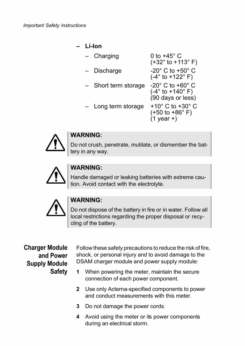
– Li-Ion
– Charging 0 to +45° C(+32° to +113° F)
– Discharge -20° C to +50° C(-4° to +122° F)
– Short term storage -20° C to +60° C(-4° to +140° F)(90 days or less)
– Long term storage +10° C to +30° C(+50 to +86° F)
(1 year +)
Charger Module
and Power Supply Module
Safety
Follow these safety precautions to reduce the risk of fire,
shock, or personal injury and to avoid damage to the
DSAM charger module and power supply module:
1 When powering the meter, maintain the secure
connection of each power component.
2 Use only Acterna-specified components to power
and conduct measurements with this meter.
3 Do not damage the power cords.
4 Avoid using the meter or its power components
during an electrical storm.
WARNING:
Do not crush, penetrate, mutilate, or dismember the bat-
tery in any way.
WARNING:
Handle damaged or leaking batteries with extreme cau-
tion. Avoid contact with the electrolyte.
WARNING:
Do not dispose of the battery in fire or in water. Follow all
local restrictions regarding the proper disposal or recy-
cling of the battery.

7/28/2019 DSAM-2500 Manual2 En
http://slidepdf.com/reader/full/dsam-2500-manual2-en 9/56
Important Safety Instructions
DSAM Product Family Quick-Start Guide Rev. E v
5 Follow all basic safety practices associated with the
use of electrical equipment.
WARNING:
Do not use this product in the vicinity of a gas leak or in
any other explosive environment.

7/28/2019 DSAM-2500 Manual2 En
http://slidepdf.com/reader/full/dsam-2500-manual2-en 10/56
Important Safety Instructions
vi DSAM Product Family Quick-Start Guide Rev. E

7/28/2019 DSAM-2500 Manual2 En
http://slidepdf.com/reader/full/dsam-2500-manual2-en 11/56
DSAM Product Family Quick-Start Guide Rev. E 1
Table of Contents
Product Overview ...............................................................................2
Initial Set-Up.......................................................................................3
Powering the Meter ............................................................................5
Using the Keypad ...............................................................................7
Using the Help System.....................................................................10
Configuring the Meter .......................................................................13
Using Measure Mode .......................................................................17
Using AutoTest Mode .......................................................................26
Using Access Mode..........................................................................30
Cloning DSAM Meters ......................................................................32
Replacing the Protective Lens..........................................................33
Contrast Adjustment (Extreme Temperature Change) .....................33
Technical Assistance ........................................................................34
Warranty Information ........................................................................35
Equipment Return Instructions .........................................................39
DSAM Specifications ........................................................................40
Power Component Specifications.....................................................44
7/28/2019 DSAM-2500 Manual2 En
http://slidepdf.com/reader/full/dsam-2500-manual2-en 12/56
Product Overview
2 DSAM Product Family Quick-Start Guide Rev. E
Product Overview
The DSAM Digital Service Activation meter family
provides a combination of DOCSIS/EuroDOCSIS cable
modem installation meters for the on-site installation
and service of high-speed data and video services.
Using exclusive digital signal processing and integrated
DOCSIS/EuroDOCSIS chipset technology, the meter
communicates with the network CMTS to verify suitable
conditions for cable modem installation from the
subscriber’s location. The DSAM is also equipped with
signal level meter capabilities, including spectrum scan-ning for ingress assessment and mini-scan analysis of
up to twelve analog and/or digital channels. The meter’s
AutoTest capability makes installations easier and more
reliable than ever before.
Acterna has incorporated exclusive DSP, DOCSIS, and
analog technology to enhance your DSAM’s usability
and provide significant flexibility as additional features
become available. Upgrading the meter can be as
simple as downloading a file from the Internet and
installing it onto the device using optional FDM utility
software.
Using this
Quick-StartGuide
We know you want to get the most out of your DSAM as
soon as possible, so we’ve designed this Quick-Start
Guide to provide the essential facts you need to know to
use your DSAM effectively.
We encourage you to read this guide completely and to
take advantage of the extensive Help system on your
DSAM (see “Using the Help System” on page 10).
This guide provides safety information, initial set-up
instructions, and important facts about powering, config-
uring, and executing the functions of the meter. The
guide also provides information about cloning DSAM
meters, sources for additional technical assistance, the
product warranty, equipment return instructions, andspecifications for the meter and its power components.

7/28/2019 DSAM-2500 Manual2 En
http://slidepdf.com/reader/full/dsam-2500-manual2-en 13/56
Initial Set-Up
DSAM Product Family Quick-Start Guide Rev. E 3
Initial Set-Up
Typically your DSAM Digital Service Activation Meter is
shipped with the following accessories:
– One (1) NiMH rechargeable battery
– One (1) charger module
– One (1) universal power supply module
– One (1) power cord
– One (1) DC connector
– One (1) shoulder strap
– Two (2) hand-straps (installed on meter)
– Five (5) replacement lenses
– One (1) quick-start guide.
Many optional accessories are available to extend your
DSAM’s functionality, versatility, and ease of use. Learn
more about optional DSAM accessories at this Internet
address: www.acterna.com/products/cable/index.html.
Installing the
battery
To install the battery:
1 Hold the meter securely with the display screen
facing away from you and the keypad in the palm of
your hand.
2 Holding the battery in your other hand with its label
facing away from you, rest the lower (contact) edge
of the battery against the raised edge at the bottom
of the meter.
3 Gently lower the battery into the cavity of the meter
until the top edge of the battery latches into place.
To remove the battery, hold the meter in the manner
described above and press the release button located
directly above the battery in the center of the back of the
meter. When released, gently pull the battery out of the
cavity in the back of the meter.
Connecting the
power components
In addition to the battery, three power components have
been shipped with your DSAM -- a charger module, a
universal power supply module, and a power cord.
7/28/2019 DSAM-2500 Manual2 En
http://slidepdf.com/reader/full/dsam-2500-manual2-en 14/56
Initial Set-Up
4 DSAM Product Family Quick-Start Guide Rev. E
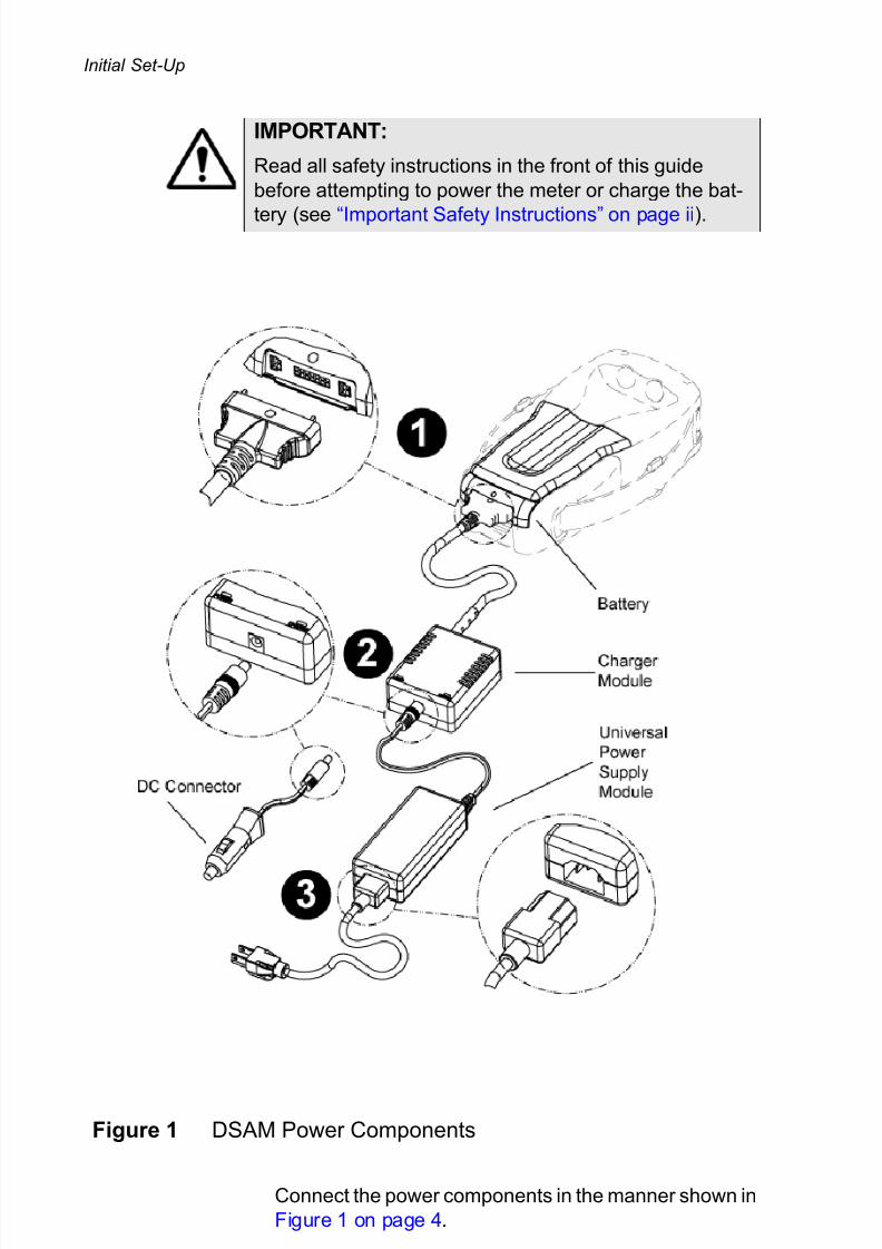
Connect the power components in the manner shown in
Figure 1 on page 4.
IMPORTANT:
Read all safety instructions in the front of this guide
before attempting to power the meter or charge the bat-
tery (see “Important Safety Instructions” on page ii).
Figure 1 DSAM Power Components
7/28/2019 DSAM-2500 Manual2 En
http://slidepdf.com/reader/full/dsam-2500-manual2-en 15/56
Powering the Meter
DSAM Product Family Quick-Start Guide Rev. E 5
Follow these three steps to connect the power compo-
nents to the DSAM battery (the battery can be in or out
of the meter):
1 Align the tabs of the charger module connector tothe slots in the battery and gently insert the
connector tabs into the battery slots.
2 Align the universal power supply module connector
(or DC connector) with the DC connection port in
the charger module and gently insert the connector
into the connection port.
3 Align the power cord connector with the universal
power supply connection port and gently insert theconnector into the connection port. Connect the
power cord plug to an AC power source when you
are ready to power the meter or charge the battery.
(If you are using the DC connector, connect it to an
appropriate 12-volt DC power source.)
Connecting the
RF cable
To conduct measurements with your DSAM, connect the
RF cable of the system you are servicing to the RF
connection port on the back panel of the meter.
Making
additionalconnections
Use the Ethernet port located on the top of the meter to
clone settings with other DSAM meters (see “Cloning
DSAM Meters” on page 32) or to synchronize your data
with optional FDM utility software (see “Using Access
Mode” on page 30).
(The headphone jack and USB ports located on the topof the meter will be used in future DSAM applications.)
Powering the Meter
IMPORTANT:
Read all safety instructions in the front of this guide
before attempting to power the meter or charge the bat-tery (see “Important Safety Instructions” on page ii).

7/28/2019 DSAM-2500 Manual2 En
http://slidepdf.com/reader/full/dsam-2500-manual2-en 16/56
Powering the Meter
6 DSAM Product Family Quick-Start Guide Rev. E
Selecting apower option
There are three ways to provide power to your DSAM.
Choose the method that best suits your working condi-
tions:
– DC power from the charger module connected to an AC power source,
– DC power from the battery alone, or
– DC power using the DC connector cord connected
to a charger module.
Charging the
batteryWith the power components properly connected (see
“DSAM Power Components” on page 4), the DSAM
battery can be charged when outside of the meter or when installed in the meter.
When you power the meter directly with an AC or a DC
power source, this source automatically charges the
battery as well on a separate path with no degradation
to the meter’s direct power. When the battery is fully
charged, the charger module provides a maintenance
charge from the power source (see “Charge LED indica-
tions” on page 7).
The charger module automatically identifies the type of
battery being charged; no battery selection configura-
tion is required.
Fast charge
temperature
range
Your DSAM charger module will not allow fast charge
mode to begin if the battery temperature is not within a
safe range for charging. To begin and maintain fast
charge mode, the battery temperature should beapproximately between 32 °F (0 °C) and 122 °F (50 °C).
Fast charge mode automatically resumes when the
battery temperature returns within this range.
Interpreting the“Charge” LED
There are two LED indicator lights on your DSAM
charger module -- the “Power” LED and the “Charge”
LED.
The green “Power” LED illuminates to indicate that thecharger module is receiving power.

7/28/2019 DSAM-2500 Manual2 En
http://slidepdf.com/reader/full/dsam-2500-manual2-en 17/56
Using the Keypad
DSAM Product Family Quick-Start Guide Rev. E 7
The “Charge” LED illuminates in red, green, or orange
to indicate the present battery and charge condition. It
may remain on constantly, or it may begin to flash. To
interpret the “Charge” LED indications, review Table 1.
For information about the charger module’s specifica-
tions, see Table 4 on page 44.
Using the Keypad
Below the display screen on the front panel of your
DSAM (Figure 2) is a keypad used to perform all func-
tions of the meter.
Table 1 Charge LED indications
LED
color
LED
activity
Battery and charge
condition
Red On
(constant)
Charger module is in fast
charge mode; maximum
charge is delivered to bat-
tery
Green On
(constant)
Fast charge cycle is com-
plete; battery is ready for
use and in maintenance
charge mode while
attached to the charger
module
Red Flashing Battery-related error or
defect detected; min/
max cell voltage or bat-tery temperature is out of
range)
Orange Flashing DC input voltage is out of
range.

7/28/2019 DSAM-2500 Manual2 En
http://slidepdf.com/reader/full/dsam-2500-manual2-en 18/56
Using the Keypad
8 DSAM Product Family Quick-Start Guide Rev. E
The keypad is comprised of:
– four Display Softkeys (directly below the display
screen) used to select screen-specific options or toselect pop-up menus associated with each key
– four directional Arrow Keys (located directly below
the two center softkeys) used to navigate up, down,
right, and left among the displayed menus and
measurement features
– an Enter Key used to select highlighted menu
items and input alphanumeric data
– an Exit Key used to depart from the currentlyviewed screen to a previously viewed option
– four Mode Keys (Figure 3) used to access the
meter’s four primary functional modes
Figure 2 DSAM Front Panel
7/28/2019 DSAM-2500 Manual2 En
http://slidepdf.com/reader/full/dsam-2500-manual2-en 19/56
Using the Keypad
DSAM Product Family Quick-Start Guide Rev. E 9
– twelve Alphanumeric Keys used for data entry and
for shortcut access to specific features (as a shift
key function)
– a Shift Key used in conjunction with the alpha-
numeric keys or the display softkeys for shortcut
access to specific features
– a Power Key used to turn the meter on and off.
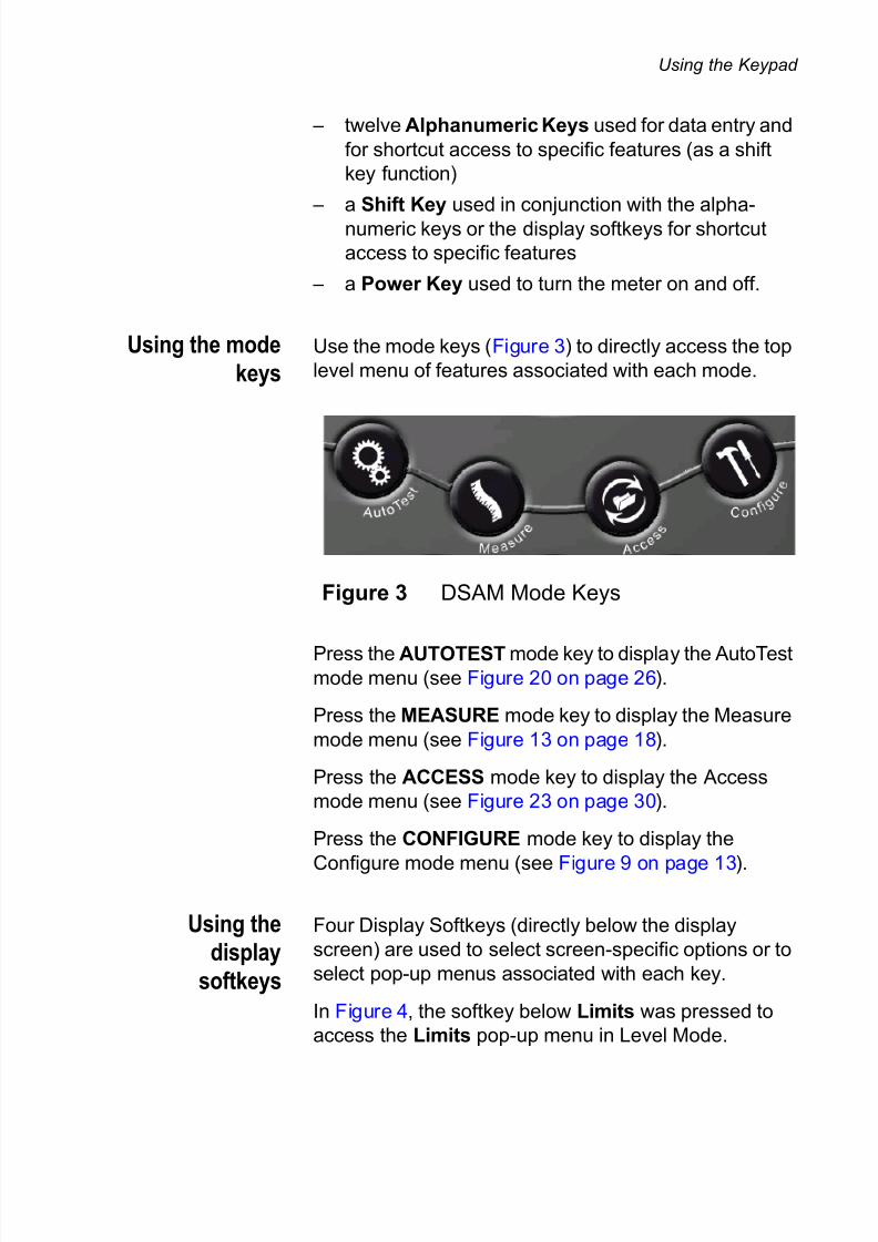
Using the mode
keysUse the mode keys (Figure 3) to directly access the top
level menu of features associated with each mode.
Press the AUTOTEST mode key to display the AutoTestmode menu (see Figure 20 on page 26).
Press the MEASURE mode key to display the Measure
mode menu (see Figure 13 on page 18).
Press the ACCESS mode key to display the Access
mode menu (see Figure 23 on page 30).
Press the CONFIGURE mode key to display the
Configure mode menu (see Figure 9 on page 13).
Using thedisplay
softkeys
Four Display Softkeys (directly below the display
screen) are used to select screen-specific options or to
select pop-up menus associated with each key.
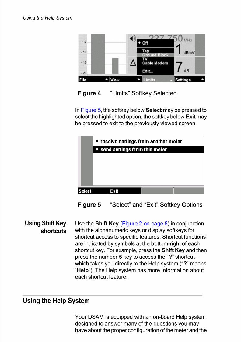
In Figure 4, the softkey below Limits was pressed to
access the Limits pop-up menu in Level Mode.
Figure 3 DSAM Mode Keys
7/28/2019 DSAM-2500 Manual2 En
http://slidepdf.com/reader/full/dsam-2500-manual2-en 20/56
Using the Help System
10 DSAM Product Family Quick-Start Guide Rev. E
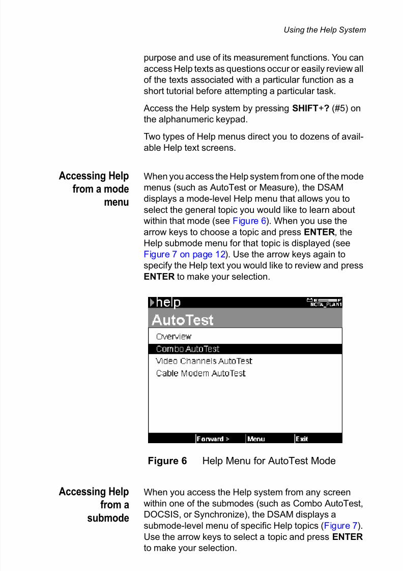
In Figure 5, the softkey below Select may be pressed to
select the highlighted option; the softkey below Exit may
be pressed to exit to the previously viewed screen.
Using Shift Key
shortcutsUse the Shift Key (Figure 2 on page 8) in conjunction
with the alphanumeric keys or display softkeys for
shortcut access to specific features. Shortcut functionsare indicated by symbols at the bottom-right of each
shortcut key. For example, press the Shift Key and then
press the number 5 key to access the “?” shortcut --
which takes you directly to the Help system (“?” means
“Help”). The Help system has more information about
each shortcut feature.
Using the Help System
Your DSAM is equipped with an on-board Help system
designed to answer many of the questions you may
have about the proper configuration of the meter and the
Figure 4 “Limits” Softkey Selected
Figure 5 “Select” and “Exit” Softkey Options
7/28/2019 DSAM-2500 Manual2 En
http://slidepdf.com/reader/full/dsam-2500-manual2-en 21/56
Using the Help System
DSAM Product Family Quick-Start Guide Rev. E 11
purpose and use of its measurement functions. You can
access Help texts as questions occur or easily review all
of the texts associated with a particular function as a
short tutorial before attempting a particular task.
Access the Help system by pressing SHIFT+? (#5) on
the alphanumeric keypad.
Two types of Help menus direct you to dozens of avail-
able Help text screens.
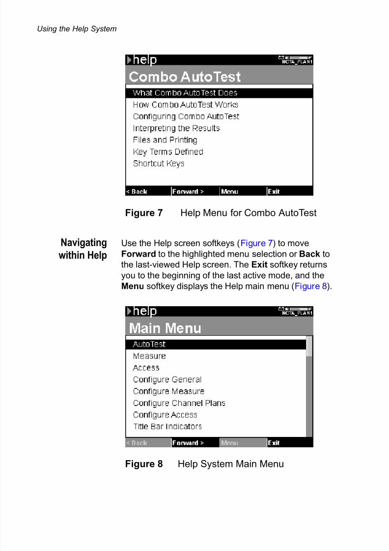
Accessing Help
from a mode
menu
When you access the Help system from one of the mode
menus (such as AutoTest or Measure), the DSAM
displays a mode-level Help menu that allows you toselect the general topic you would like to learn about
within that mode (see Figure 6). When you use the
arrow keys to choose a topic and press ENTER, the
Help submode menu for that topic is displayed (see
Figure 7 on page 12). Use the arrow keys again to
specify the Help text you would like to review and press
ENTER to make your selection.
Accessing Help
from a
submode
When you access the Help system from any screen
within one of the submodes (such as Combo AutoTest,DOCSIS, or Synchronize), the DSAM displays a
submode-level menu of specific Help topics (Figure 7).
Use the arrow keys to select a topic and press ENTER
to make your selection.
Figure 6 Help Menu for AutoTest Mode
7/28/2019 DSAM-2500 Manual2 En
http://slidepdf.com/reader/full/dsam-2500-manual2-en 22/56
Using the Help System
12 DSAM Product Family Quick-Start Guide Rev. E
Navigating
within HelpUse the Help screen softkeys (Figure 7) to move
Forward to the highlighted menu selection or Back to
the last-viewed Help screen. The Exit softkey returns
you to the beginning of the last active mode, and the
Menu softkey displays the Help main menu (Figure 8).
Figure 7 Help Menu for Combo AutoTest
Figure 8 Help System Main Menu

7/28/2019 DSAM-2500 Manual2 En
http://slidepdf.com/reader/full/dsam-2500-manual2-en 23/56
Configuring the Meter
DSAM Product Family Quick-Start Guide Rev. E 13
Configuring the Meter
Accurate and complete configuration of your DSAM
assures reliable measurement performance and
enhanced ease of use. To take full advantage of the
many features your DSAM offers, be sure to properly
configure the meter to respond effectively to your
working conditions and to meet your data management
needs.
Using Help
whenconfiguring the
meter
The Help system on your DSAM contains Help texts
addressing each configuration topic.
Press SHIFT+? (#5) to access the Help system.
In addition to the Help texts linked to each topic in the
four configuration modes, you may want to review the
Help texts addressing configuration in the AutoTest and
Measure modes for more complete information (Help
texts such as, “Configuring Video Channels AutoTest”
and Configuring DOCSIS”).
Selecting a
configurationmode
To view the CONFIGURE GENERAL menu (see
Figure 9), press the CONFIGURE mode key (Figure 3
on page 9), then press the General softkey.
Figure 9 Configure Mode General Menu

7/28/2019 DSAM-2500 Manual2 En
http://slidepdf.com/reader/full/dsam-2500-manual2-en 24/56
Configuring the Meter
14 DSAM Product Family Quick-Start Guide Rev. E
Four configure modes are indicated by softkey tabs at
the bottom of the display screen -- General, Measure,
Channel Plan, and Access. Each configuration mode
has a menu of configurable items specific to that mode.
To access a Configure Mode menu, press the softkey
directly below the mode you wish to view. The
CONFIGURE GENERAL menu is displayed when you
press the CONFIGURE mode key for the first time. After
that, the meter will display the most recently displayed
Configure Mode each time you return to the configura-
tion menus by pressing the CONFIGURE mode key.
When you have displayed the mode menu you prefer,
use the arrow keys to highlight the item you intend to
configure and press ENTER.
GeneralConfiguration
To view the CONFIGURE GENERAL menu, press the
General softkey when in Configure mode.
Use general configuration to:
– adjust contrast
– adjust sounds
– optimize battery life
– enter your personal information
– set date and time
– configure printer
– configure network
– configure ports
– set local preferences
– administer security
– choose a utility
– clone settings with other DSAM meters
– choose a diagnostic
Language
selection andlocal preferences
Select Regional Preferences on the CONFIGURE
GENERAL menu to specify the type of language, dateformat, signal level units, temperature units, and digital
performance units you prefer.

7/28/2019 DSAM-2500 Manual2 En
http://slidepdf.com/reader/full/dsam-2500-manual2-en 25/56
Configuring the Meter
DSAM Product Family Quick-Start Guide Rev. E 15
Press ENTER to open the LANGUAGE edit box and use
the arrow keys to highlight the selection you prefer.
Then press ENTER to complete the edit.
Each edit box may be edited individually. To save time,you can edit fewer boxes by first editing the PRESET TO
edit box (which automatically selects default settings for
date format, signal level units, temperature units, and
digital performance units based upon the locale you
choose).
MeasurementConfiguration
To view the CONFIGURE MEASURE menu (Figure 10),
press the CONFIGURE mode key (Figure 3 on page 9),
then press the Measure softkey.
Use measure configuration to specify:
– limit sets,
– DOCSIS throughput, and
– other (measurement) settings, such as the roving
MAC address for cable modem tests.
Use the Help system on your DSAM to learn more about
each configuration mode. Press SHIFT+? to find outwhat each option does, how it works, how to configure
it, how to interpret the results, and more.
Figure 10 Configure Mode Measure Menu
7/28/2019 DSAM-2500 Manual2 En
http://slidepdf.com/reader/full/dsam-2500-manual2-en 26/56
Configuring the Meter
16 DSAM Product Family Quick-Start Guide Rev. E
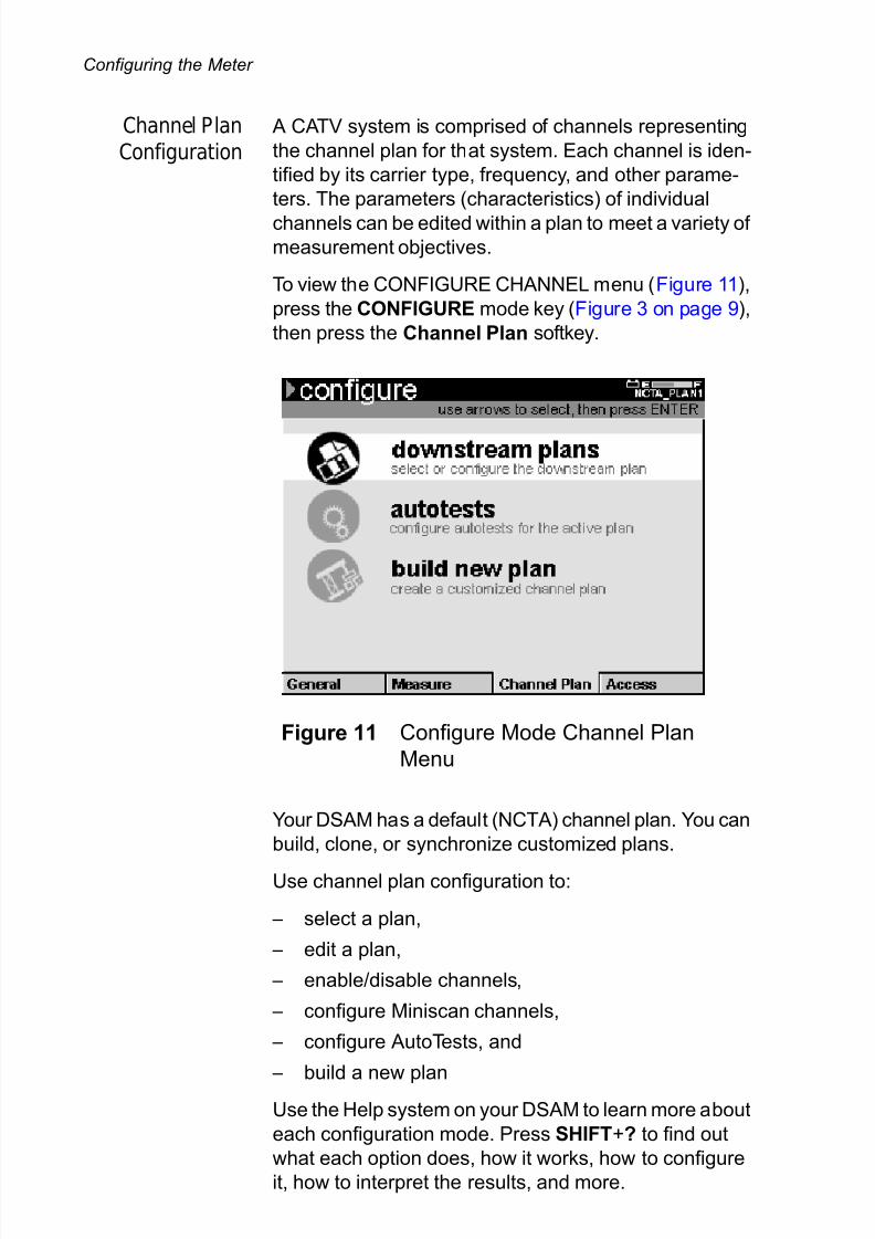
Channel PlanConfiguration
A CATV system is comprised of channels representing
the channel plan for that system. Each channel is iden-
tified by its carrier type, frequency, and other parame-
ters. The parameters (characteristics) of individual
channels can be edited within a plan to meet a variety of measurement objectives.
To view the CONFIGURE CHANNEL menu (Figure 11),
press the CONFIGURE mode key (Figure 3 on page 9),
then press the Channel Plan softkey.
Your DSAM has a default (NCTA) channel plan. You can
build, clone, or synchronize customized plans.
Use channel plan configuration to:
– select a plan,
– edit a plan,
– enable/disable channels,
– configure Miniscan channels,
– configure AutoTests, and
– build a new plan
Use the Help system on your DSAM to learn more about
each configuration mode. Press SHIFT+? to find out
what each option does, how it works, how to configure
it, how to interpret the results, and more.
Figure 11 Configure Mode Channel Plan
Menu

7/28/2019 DSAM-2500 Manual2 En
http://slidepdf.com/reader/full/dsam-2500-manual2-en 27/56
Using Measure Mode
DSAM Product Family Quick-Start Guide Rev. E 17
AccessConfiguration
To view the CONFIGURE ACCESS menu (Figure 12),
press the CONFIGURE mode key (Figure 3 on page 9),
then press the Access softkey.
Use pc connection to select your preferred PC connec-
tion (Ethernet or RF) and to define its IP address.
Use the WFA browser settings to enter the preferred
ethernet or RF connection, home URL, proxy server
parameters (optional) and CM diagnostic web page
information.
Use the Help system on your DSAM to learn more about
each configuration mode. Press SHIFT+? to find out
what each option does, how it works, how to configure
it, how to interpret the results, and more.
Using Measure Mode
Three measurement modes are indicated by softkey
tabs at the bottom of the display screen -- Basic,
Service, and Spectrum. Each measurement mode has
a menu of measurement items specific to that mode.
To access a Basic Mode menu, press the softkey
directly below the mode you wish to view. The
MEASURE BASIC menu is displayed when you press
the MEASURE mode key for the first time. After that, the
Figure 12 Configure Mode Access Menu
7/28/2019 DSAM-2500 Manual2 En
http://slidepdf.com/reader/full/dsam-2500-manual2-en 28/56
Using Measure Mode
18 DSAM Product Family Quick-Start Guide Rev. E
meter will display the most recently displayed Measure
mode each time you return to the Measure menus by
pressing the MEASURE mode key.
When you have displayed the mode menu you prefer,use the arrow keys to highlight the item you intend to
configure and press ENTER.
You are ready to perform tests in Measure mode only
when
– the meter is receiving power,
– the RF cable is connected to the meter (on the back
panel), and
– your DSAM has been configured to conduct
measurements (see “Configuring the Meter” on
page 13).
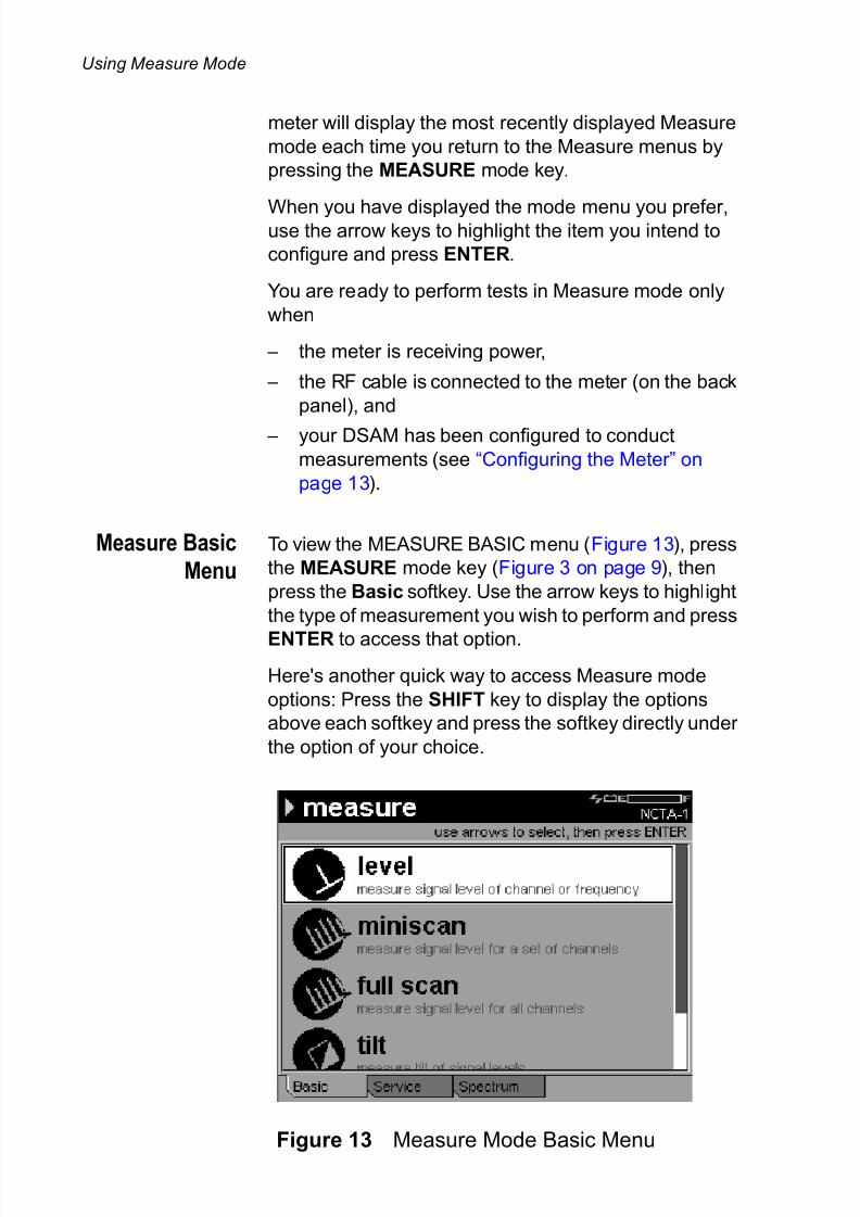
Measure Basic
MenuTo view the MEASURE BASIC menu (Figure 13), press
the MEASURE mode key (Figure 3 on page 9), then
press the Basic softkey. Use the arrow keys to highlight
the type of measurement you wish to perform and press
ENTER to access that option.
Here's another quick way to access Measure mode
options: Press the SHIFT key to display the options
above each softkey and press the softkey directly under
the option of your choice.
Figure 13 Measure Mode Basic Menu

7/28/2019 DSAM-2500 Manual2 En
http://slidepdf.com/reader/full/dsam-2500-manual2-en 29/56
Using Measure Mode
DSAM Product Family Quick-Start Guide Rev. E 19
Use Measure Basic Menu to select:
– level - views and analyzes the signal level of each
carrier within a channel (as defined by the active
channel plan), – miniscan - views and analyzes the carrier levels of
up to twelve channels and displays the results on a
single screen,
– full scan - views and analyzes the carrier levels of
up to 999 channels at a time and displays the video
and audio levels of a carrier on a single screen,
– tilt - analyzes and displays the signal level and tilt
calculation of up to twelve channels and displaysthe results on a single screen, and
– constellation - (only on specific DSAM models or
options) displays a constellation diagram of the
demodulated digital Quadrature Amplitude Modula-
tion (QAM) type (64 QAM or 256 QAM) signal prior
to error correction
Use the Help system on your DSAM to learn more about
each measurement mode. Press SHIFT+? to find out
what each option does, how it works, how to configure
it, how to interpret the results, and more.
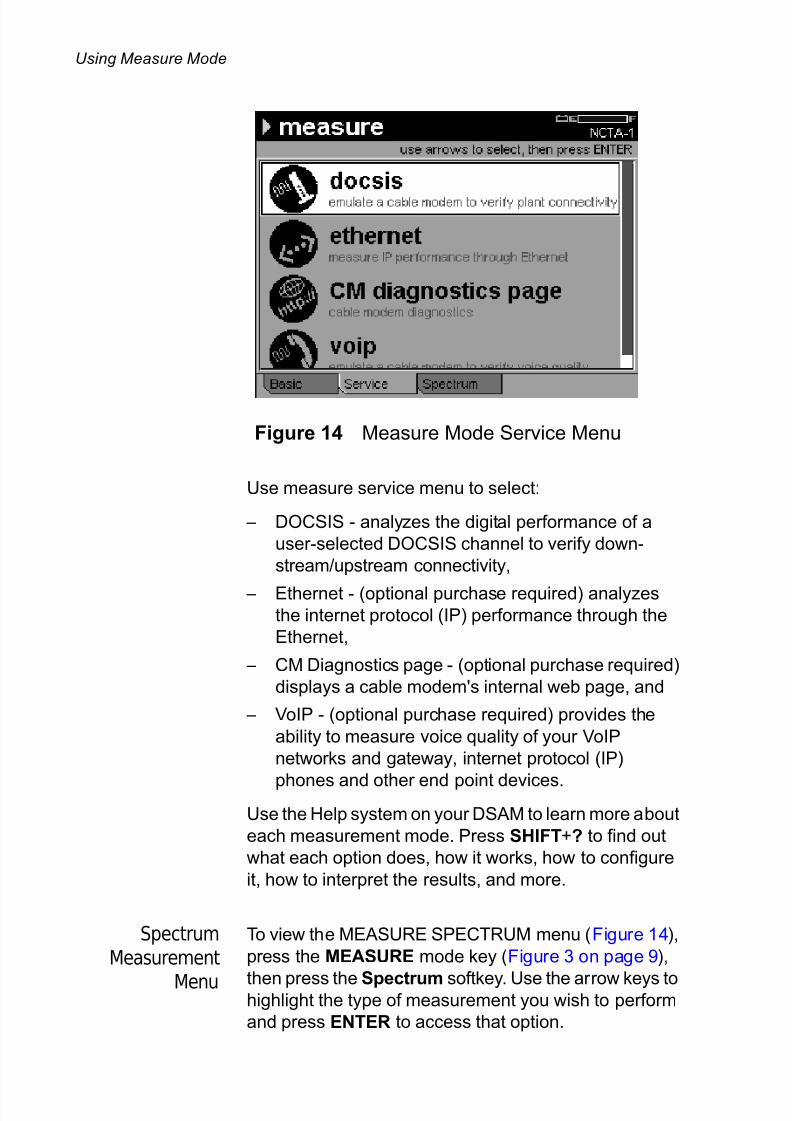
ServiceMeasurement
Menu
To view the MEASURE SERVICE menu (Figure 14),
press the MEASURE mode key (Figure 3 on page 9),
then press the Service softkey. Use the arrow keys to
highlight the type of measurement you wish to perform
and press ENTER to access that option.
Here's another quick way to access Measure mode
options: Press the SHIFT key to display the options
above each softkey and press the softkey directly under
the option of your choice.
7/28/2019 DSAM-2500 Manual2 En
http://slidepdf.com/reader/full/dsam-2500-manual2-en 30/56
Using Measure Mode
20 DSAM Product Family Quick-Start Guide Rev. E
Use measure service menu to select:
– DOCSIS - analyzes the digital performance of a
user-selected DOCSIS channel to verify down-
stream/upstream connectivity,
– Ethernet - (optional purchase required) analyzesthe internet protocol (IP) performance through the
Ethernet,
– CM Diagnostics page - (optional purchase required)
displays a cable modem's internal web page, and
– VoIP - (optional purchase required) provides the
ability to measure voice quality of your VoIP
networks and gateway, internet protocol (IP)
phones and other end point devices.Use the Help system on your DSAM to learn more about
each measurement mode. Press SHIFT+? to find out
what each option does, how it works, how to configure
it, how to interpret the results, and more.
Spectrum
Measurement
Menu
To view the MEASURE SPECTRUM menu (Figure 14),
press the MEASURE mode key (Figure 3 on page 9),
then press the Spectrum softkey. Use the arrow keys tohighlight the type of measurement you wish to perform
and press ENTER to access that option.
Figure 14 Measure Mode Service Menu

7/28/2019 DSAM-2500 Manual2 En
http://slidepdf.com/reader/full/dsam-2500-manual2-en 31/56
Using Measure Mode
DSAM Product Family Quick-Start Guide Rev. E 21
Here's another quick way to access Measure mode
options: Press the SHIFT key to display the options
above each softkey and press the softkey directly under
the option of your choice.
Use measure spectrum menu to select:
– upstream spectrum - views and analyzes noise on
the upstream path (return path),
– downstream spectrum - (optional purchase
required) view the entire CATV downstream spec-
trum frequency range (40 MHz to 1 GHz) in 50 Mhz
(default) frequency spans with a dynamic range of
60 dB, and
– field view - (optional purchase required) analyzes
and displays ingress and distortion on the upstream
path (return path) as viewed by PathTrak or Phasor
system at the node and the headend. It identifies
the frequency at which ingress occurs and displays
the level value.
Use the Help system on your DSAM to learn more about
each measurement mode. Press SHIFT+? to find out
what each option does, how it works, how to configureit, how to interpret the results, and more.
Figure 15 Measure Mode Spectrum Menu
7/28/2019 DSAM-2500 Manual2 En
http://slidepdf.com/reader/full/dsam-2500-manual2-en 32/56
Using Measure Mode
22 DSAM Product Family Quick-Start Guide Rev. E
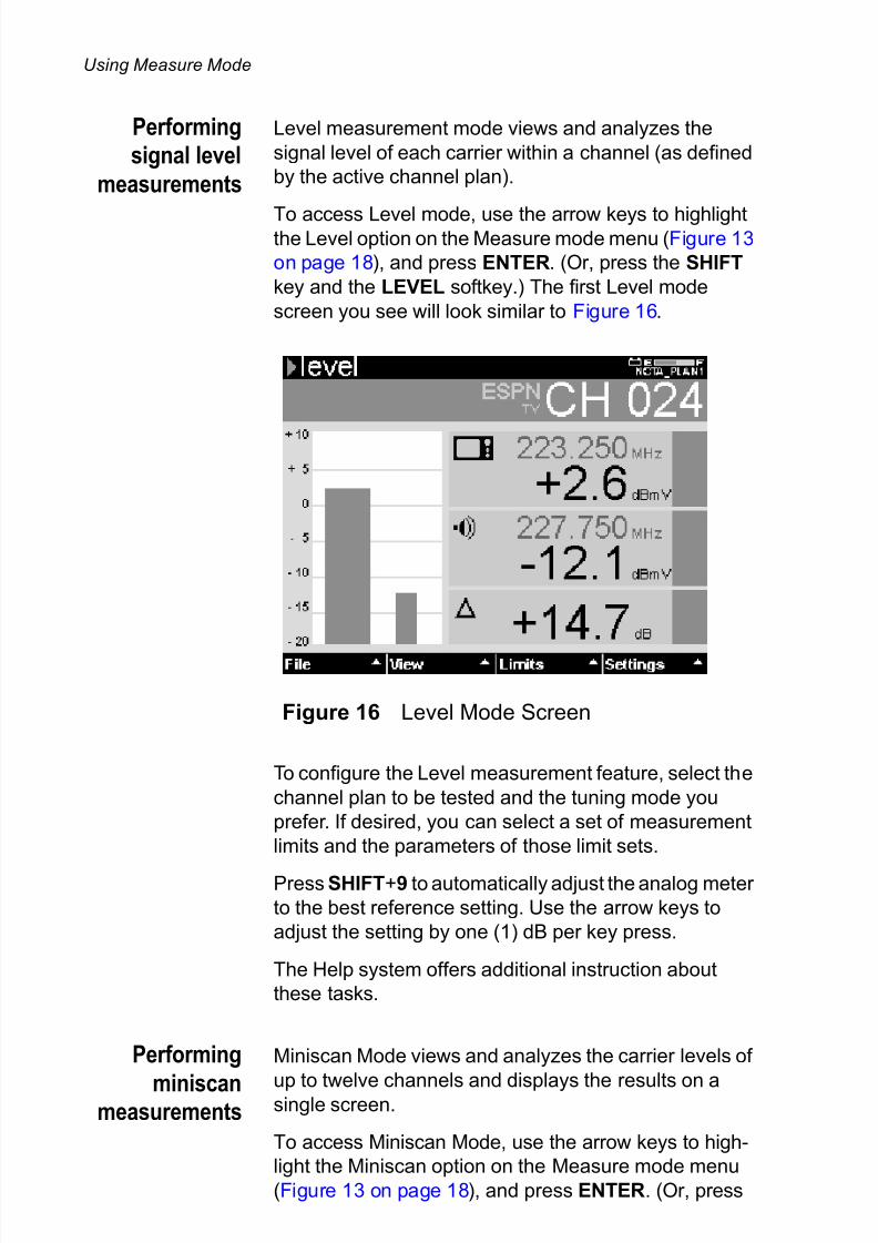
Performingsignal level
measurements
Level measurement mode views and analyzes the
signal level of each carrier within a channel (as defined
by the active channel plan).
To access Level mode, use the arrow keys to highlightthe Level option on the Measure mode menu (Figure 13
on page 18), and press ENTER. (Or, press the SHIFT
key and the LEVEL softkey.) The first Level mode
screen you see will look similar to Figure 16.
To configure the Level measurement feature, select the
channel plan to be tested and the tuning mode you
prefer. If desired, you can select a set of measurement
limits and the parameters of those limit sets.
Press SHIFT+9 to automatically adjust the analog meter
to the best reference setting. Use the arrow keys to
adjust the setting by one (1) dB per key press.
The Help system offers additional instruction about
these tasks.
Performing
miniscanmeasurements
Miniscan Mode views and analyzes the carrier levels of
up to twelve channels and displays the results on asingle screen.
To access Miniscan Mode, use the arrow keys to high-
light the Miniscan option on the Measure mode menu
(Figure 13 on page 18), and press ENTER. (Or, press
Figure 16 Level Mode Screen

7/28/2019 DSAM-2500 Manual2 En
http://slidepdf.com/reader/full/dsam-2500-manual2-en 33/56
Using Measure Mode
DSAM Product Family Quick-Start Guide Rev. E 23
the SHIFT key and the MINISCAN softkey.) The first
Miniscan Mode screen you see will look similar to
Figure 17.
To configure the Miniscan measurement feature, select:
the channel plan to be tested, up to twelve channels for Miniscan measurement, a set of measurement limits
(based on test location), the parameters of those limit
sets, and the resolution of the Miniscan graph for the
best viewing.
Use the up and down arrow keys to adjust the reference
setting of the graph by one (1) dB per key press. Use the
right and left arrow keys to move the vertical marker to
the next or previous channel.
The Help system offers additional instruction about
these tasks.
Performing
spectrum
measurements
Upstream Spectrum Mode views and analyzes ingress
and distortion on the upstream (return) path. Initial
measurements typically occur at the ground block with
the home disconnected from the network.
To access Upstream Spectrum Mode, use the arrow
keys to highlight the Upstream Spectrum option on the
Measure mode menu (Figure 15 on page 21), and press
Figure 17 Miniscan Mode Screen

7/28/2019 DSAM-2500 Manual2 En
http://slidepdf.com/reader/full/dsam-2500-manual2-en 34/56
Using Measure Mode
24 DSAM Product Family Quick-Start Guide Rev. E
ENTER. (Or, press the SHIFT key and the SPECTRUM
softkey.) The first Upstream Spectrum mode screen you
see will look similar to Figure 18.
To configure Upstream Spectrum Mode, select the
measurement limit option (or turn it off), and (if it is on)set an appropriate pass/fail limit value for your installa-
tion. Position the marker at each frequency to display
the level value.
Use the up and down arrow keys to adjust the reference
setting of the graph by one (1) dB per key press. Use the
right and left arrow keys to move the vertical marker to
the next or previous measurement data point.
The Help system offers additional instruction about
these tasks.
Prior to an installation, use upstream spectrum
measurements to verify that the system does not
exceed the maximum acceptable level for ingress. After
an installation, check the level again to compare the
previous reading and confirm that install procedures or
components did not create new sources of ingress.
Figure 18 Upstream Spectrum Mode Screen
7/28/2019 DSAM-2500 Manual2 En
http://slidepdf.com/reader/full/dsam-2500-manual2-en 35/56
Using Measure Mode
DSAM Product Family Quick-Start Guide Rev. E 25
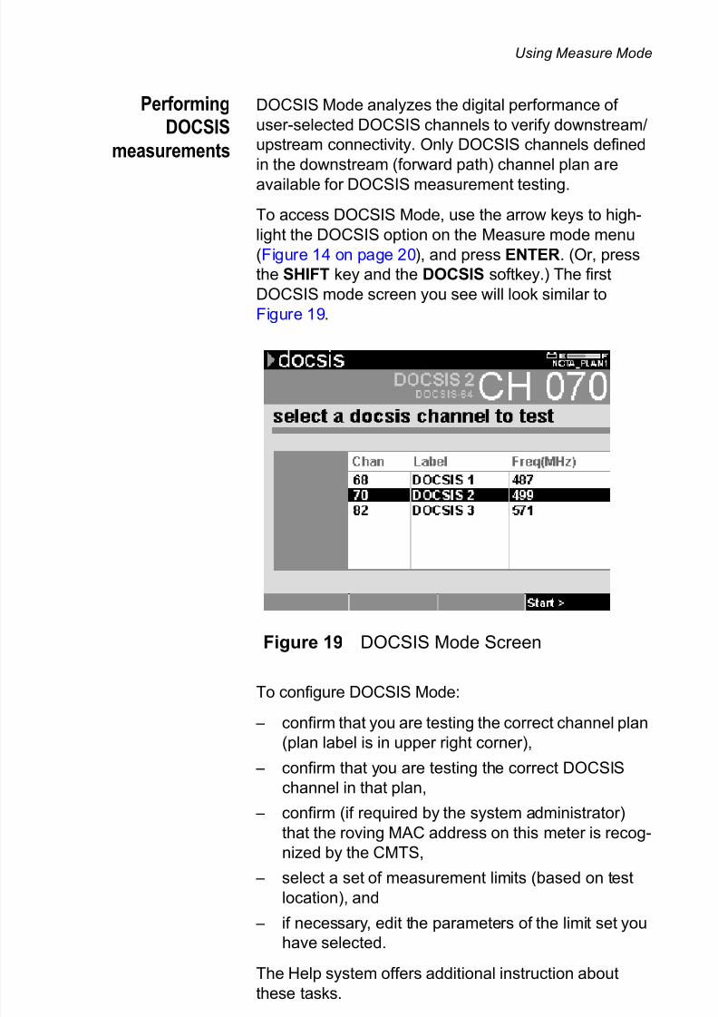
PerformingDOCSIS
measurements
DOCSIS Mode analyzes the digital performance of
user-selected DOCSIS channels to verify downstream/
upstream connectivity. Only DOCSIS channels defined
in the downstream (forward path) channel plan are
available for DOCSIS measurement testing.
To access DOCSIS Mode, use the arrow keys to high-
light the DOCSIS option on the Measure mode menu
(Figure 14 on page 20), and press ENTER. (Or, press
the SHIFT key and the DOCSIS softkey.) The first
DOCSIS mode screen you see will look similar to
Figure 19.
To configure DOCSIS Mode:
– confirm that you are testing the correct channel plan
(plan label is in upper right corner),
– confirm that you are testing the correct DOCSIS
channel in that plan,
– confirm (if required by the system administrator)
that the roving MAC address on this meter is recog-
nized by the CMTS,
– select a set of measurement limits (based on test
location), and
– if necessary, edit the parameters of the limit set you
have selected.
The Help system offers additional instruction about
these tasks.
Figure 19 DOCSIS Mode Screen

7/28/2019 DSAM-2500 Manual2 En
http://slidepdf.com/reader/full/dsam-2500-manual2-en 36/56
Using AutoTest Mode
26 DSAM Product Family Quick-Start Guide Rev. E
Using AutoTest Mode
AutoTests are automated test sequences. Four types of
user-configurable AutoTests are available on this meter:
– Combo AutoTest - a user-configured sequential
combination of Video Channels AutoTest and Cable
Modem AutoTest,
– Video Channels AutoTest - user-configured level
measurements of a series of analog and/or digital
video channels,
– Cable Modem AutoTest - user-configured verifica-
tion of upstream/downstream connectivity, ranging
emulation, and quality parameter measurements of
one or more DOCSIS channels, and
– TechComplete Closeout Test - (optional purchase
required) user-configured combination of tests. The
tests can be any combination of testing on video
channels and DOCSIS tests such as ranging, regis-
tration, throughput or packet loss.
To view the AUTOTEST INStALL menu (Figure 20),
press the Install softkey when in Autotest mode. Use
the arrow keys to highlight the type of AutoTest
measurement you wish to perform and press ENTER to
access that option.
Figure 20 AutoTest Install Menu

7/28/2019 DSAM-2500 Manual2 En
http://slidepdf.com/reader/full/dsam-2500-manual2-en 37/56
Using AutoTest Mode
DSAM Product Family Quick-Start Guide Rev. E 27
You are ready to perform tests in AutoTest mode only
when
– the meter is receiving power,
– the RF cable is connected to the meter (on the backpanel), and
– your DSAM has been configured to conduct
AutoTest measurements (see “Configuring the
Meter” on page 13).
Use the Help system on your DSAM to learn more about
each AutoTest. Press SHIFT+? to find out what each
test does, how it works, how to configure it, how to inter-
pret the results, and more.
Using
ComboAutoTest
To access Combo AutoTest mode, use the arrow keys to
highlight the ComboTest option on the AutoTest mode
menu (Figure 20 on page 26), and press ENTER. The
first Combo AutoTest mode screen you see will look
similar to Figure 21.
Each Combo AutoTest is based on three types of config-
uration:
– your configuration of one Video Channels AutoTest
and one Cable Modem AutoTest,
– the parameters of your limit sets, and
Figure 21 Combo AutoTest Mode Screen

7/28/2019 DSAM-2500 Manual2 En
http://slidepdf.com/reader/full/dsam-2500-manual2-en 38/56
Using AutoTest Mode
28 DSAM Product Family Quick-Start Guide Rev. E
– your selection of a set of measurement limits
(based on test location).
The Help system offers additional instruction about
these tasks. After a limit set has been selected, press the START
softkey and Combo AutoTest measures the signal
performance of all assigned channels in the Combo Test
configuration.
Using Video
Channels
AutoTest
To access Video Channels AutoTest mode, use the
arrow keys to highlight the Video Channels option on the
AutoTest mode menu (Figure 20 on page 26), and pressENTER. The first Video Channels AutoTest mode
screen you see will look similar to the Combo AutoTest
screen shown in Figure 21.
Each Video Channels AutoTest is based on three types
of configuration:
– the parameters of your limit sets,
– your selection of channels to be tested, and
– your selection of a set of measurement limits
(based on test location).
The Help system offers additional instruction about
these tasks.
After a limit set has been selected, press the START
softkey (Figure 21 on page 27) and the AutoTest
sequentially measures the signal performance of all
assigned channels in the Video Channels AutoTestconfiguration.
Using Cable
Modem
AutoTest
To access Cable Modem AutoTest mode, use the arrow
keys to highlight the Cable Modem option on the
AutoTest mode menu (Figure 20 on page 26), and press
ENTER. The first Cable Modem AutoTest mode screen
you see will look similar to the Combo AutoTest screen
shown in Figure 21 on page 27.
Cable Modem AutoTests are configured in the same
manner as Video Channels AutoTests. To perform this
test, first select
– the parameters of your limit sets,
7/28/2019 DSAM-2500 Manual2 En
http://slidepdf.com/reader/full/dsam-2500-manual2-en 39/56
Using AutoTest Mode
DSAM Product Family Quick-Start Guide Rev. E 29
– your selection of channels to be tested, and
– your selection of a set of measurement limits
(based on test location).
The Help system offers additional instruction aboutthese tasks.
After a limit set has been selected, press the START
softkey (Figure 21 on page 27) and the AutoTest
sequentially measures the performance of all assigned
channels in the Cable Modem AutoTest configuration.
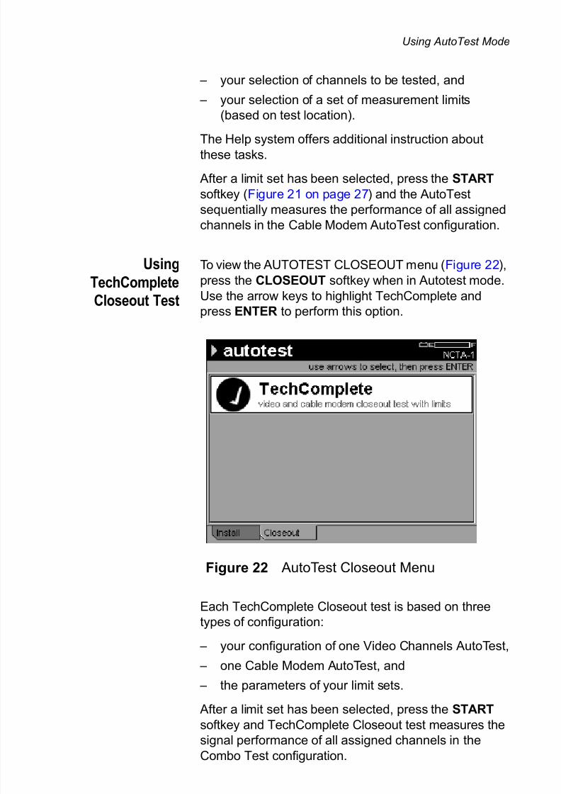
Using
TechCompleteCloseout Test
To view the AUTOTEST CLOSEOUT menu (Figure 22),
press the CLOSEOUT softkey when in Autotest mode.Use the arrow keys to highlight TechComplete and
press ENTER to perform this option.
Each TechComplete Closeout test is based on three
types of configuration:
– your configuration of one Video Channels AutoTest,
– one Cable Modem AutoTest, and
– the parameters of your limit sets.
After a limit set has been selected, press the START
softkey and TechComplete Closeout test measures the
signal performance of all assigned channels in the
Combo Test configuration.
Figure 22 AutoTest Closeout Menu
7/28/2019 DSAM-2500 Manual2 En
http://slidepdf.com/reader/full/dsam-2500-manual2-en 40/56
Using Access Mode
30 DSAM Product Family Quick-Start Guide Rev. E
Use the Help system on your DSAM to learn more about
the TechComplete Closeout test. Press SHIFT+? to find
out how it works, how to configure it, how to interpret the
results, and more.
Using Access Mode
Use Access mode to efficiently manage your measure-
ment files and folders. You can also use Access to
synchronize your data with optional FDM utility soft-
ware. The Help system offers additional instruction
about these tasks.
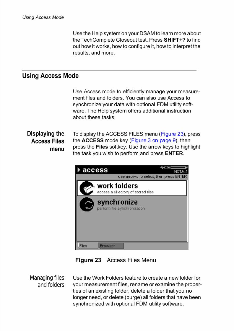
DIsplaying the
Access Files
menu
To display the ACCESS FILES menu (Figure 23), press
the ACCESS mode key (Figure 3 on page 9), then
press the Files softkey. Use the arrow keys to highlight
the task you wish to perform and press ENTER.
Managing filesand folders
Use the Work Folders feature to create a new folder for
your measurement files, rename or examine the proper-
ties of an existing folder, delete a folder that you nolonger need, or delete (purge) all folders that have been
synchronized with optional FDM utility software.
Figure 23 Access Files Menu

7/28/2019 DSAM-2500 Manual2 En
http://slidepdf.com/reader/full/dsam-2500-manual2-en 41/56
Using Access Mode
DSAM Product Family Quick-Start Guide Rev. E 31
Synchronizingyour data
Use optional FDM utility software to receive, transfer,
manage, and archive the measurement data of this (and
other) DSAM meters. You can also use synchronization
with the software to receive firmware upgrades.
Synchronize using the Ethernet port on the top of themeter. If only measurement files or channel plans are
being synchronized you may also synchronize over RF.
DIsplaying the
AccessBrowser menu
To display the ACCESS BROWSER menu (Figure 24),
press the ACCESS mode key (Figure 3 on page 9),
then press the Browser softkey. Use the arrow keys to
highlight the task you wish to perform and press
ENTER.
Use Access Browser menu to select:
– WFA browser - used to save, send, and receive
various applications and system information,
– local browser - used to open a saved Browser page,
and
– web access test - The Web Access Test connects to
an Acterna test page on the internet to ensure
internet connectivity. It accesses a single screen for view only.
Figure 24 Access Browser Menu

7/28/2019 DSAM-2500 Manual2 En
http://slidepdf.com/reader/full/dsam-2500-manual2-en 42/56
Cloning DSAM Meters
32 DSAM Product Family Quick-Start Guide Rev. E
Use the Help system on your DSAM to learn more about
each Access mode. Press SHIFT+? to find out what
each option does, how it works, how to configure it, how
to interpret the results, and more.
Cloning DSAM Meters
Use the CLONE feature to transfer DSAM settings from
or to this meter.
The Help system offers additional instruction about
these tasks.
To access the CLONE configuration screen (Figure 25),
1 Press the CONFIGURE mode key.
2 To display the Configure General mode menu
(Figure 9 on page 13), press GENERAL softkey.
3 Use the arrow keys to highlight Clone.
4 Press ENTER.
Use an Ethernet crossover cable or a standard Ethernet
cable with a crossover adapter to connect the DSAM
meters. The Ethernet port is on the top of the meter.
Figure 25 Configure General Clone Screen

7/28/2019 DSAM-2500 Manual2 En
http://slidepdf.com/reader/full/dsam-2500-manual2-en 43/56
Replacing the Protective Lens
DSAM Product Family Quick-Start Guide Rev. E 33
Replacing the Protective Lens
Your DSAM is shipped with one protective lens covering
the display screen and five additional protective lenses.
These lenses are coated on both sides, so you need not
worry about which side of the lens should face up or
down. We recommend that you use only one lens at a
time to protect the display screen. Replace the lens as it
becomes damaged, smudged, or soiled.
To replace a lens
1 Gently insert your fingernail or a small coin into the
thin rectangular notch centered directly below the
display screen and push forward (not down) until
the installed lens begins to bend at the sides in the
shape of a small arc. Caution: To avoid display
screen damage, do not use sharp objects (such
as hand tools or writing implements) to perform
this step.
2 With the other hand, gently grab the sides of the
lens and pull the lens tabs out of the holes in themeter
3 Insert the tabs of the replacement lens into the
holes at the top of the display screen and gently
bend the lens to insert the tabs at the bottom of the
lens into the holes at the bottom of the screen.
Contrast Adjustment (Extreme Temperature Change)
Your DSAM provides two modes of contrast adjustment
(AUTO and MANUAL). The AUTO mode provides a
limited contrast adjustment based upon the sensed
temperature range. The MANUAL mode provides a full
contrast adjustment across the entire operational
temperature range (0 to +120 degrees Fahrenheit or -20
to +50 degrees Celsius).To adjust the contrast
1 To quickly access the ADJUST CONTRAST config-
uration screen, press SHIFT 7.

7/28/2019 DSAM-2500 Manual2 En
http://slidepdf.com/reader/full/dsam-2500-manual2-en 44/56
Technical Assistance
34 DSAM Product Family Quick-Start Guide Rev. E
2 To switch between contrast modes (AUTO or
MANUAL), press the softkey farthest to the right.
3 Adjust the degree of difference between the lightest
and darkest areas of the screen by using the rightand left arrow keys to move the contrast indicator
(slider) on the ADJUST CONTRAST configuration
screen.
Technical Assistance
If you need assistance or have questions related to the
use of this product, call or e-mail Acterna’s Technical
Assistance Center for customer support.
NOTE:
– When an extreme change in temperature is
encountered the MANUAL mode is highly
recommended.
– When AUTO is displayed the DSAM is in the
MANUAL mode and vice versa.
– The factory default mode is AUTO.
NOTE:
To perform a repetitive contrast adjustment, press
and hold the right or left arrow key. The factory
default for screen contrast is 50%.
Table 2 Technical assistance centers
Region Phone Number
Americas 1-866-ACTERNA
301-353-1550
(1-866-228-3762)
Cable TV/
Multimedia
Products
1-866-ACTERNA (1-866-228-3762)
Brazil 0800-7015370
4617 3839
4617 3729

7/28/2019 DSAM-2500 Manual2 En
http://slidepdf.com/reader/full/dsam-2500-manual2-en 45/56
Warranty Information
DSAM Product Family Quick-Start Guide Rev. E 35
During off-hours, you can request assistance by doing
one of the following: leave a voice mail message at the
Technical Assistance number in your region; e-mail
North American Technical Assistance Center,
[email protected], or European Technical Assistance
Center, [email protected]; or submit your ques-
tion using our online Technical Assistance Request form
at www.acterna.com.
Warranty Information
The warranties described herein shall apply to all
commercially available Acterna products. Any additional
or different warranties shall apply only if agreed to by
Acterna in writing. These warranties are not transferable
without the express written consent of Acterna.
Hardware Warranty — Acterna warrants that HardwareProduct sold to customer shall, under normal use and
service, be free from defects in materials and workman-
ship. The warranty period shall be one (1) year for main-
frames and options (parts and labor), and (1) one year
for accessories and field-replaceable batteries. If instal-
Europe, Africa, and
Mid-East
+800 882 85822(European Freephone)
(Acterna UK) [email protected]
+49 (0) 6172 59 11 00
(Acterna Germany)
+33 (0) 1 39 30 24 24
(Acterna France)
Asia and the
Pacific
+852 2892 0990
(Hong Kong)
+8610 6833 7477
(Beijing-China)
Australia +61 3 9690 6700
Table 2 Technical assistance centers (Continued)
Region Phone Number

7/28/2019 DSAM-2500 Manual2 En
http://slidepdf.com/reader/full/dsam-2500-manual2-en 46/56
Warranty Information
36 DSAM Product Family Quick-Start Guide Rev. E
lation services have been ordered, the warranty period
shall begin on the earlier of (1) completion of installation,
or (2) thirty (30) days after shipment to Customer. If
Installation Services have not been ordered, the
warranty period shall begin upon shipment to Customer.Hereafter these periods of time shall be collectively
referred to as the “Initial Warranty Period.”
Acterna’s obligation and customer’s sole remedy under
this Hardware Warranty is limited to the repair or
replacement, at Acterna’s option, of the defective
product. Acterna shall have no obligation to remedy any
such defect if it can be shown: (a) that the Product was
altered, repaired, or reworked by any party other than Acterna without Acterna’s written consent; (b) that such
defects were the result of customer’s improper storage,
mishandling, abuse, or misuse of Product; (c) that such
defects were the result of customer’s use of Product in
conjunction with equipment electronically or mechani-
cally incompatible or of an inferior quality; or (d) that the
defect was the result of damage by fire, explosion,
power failure, or any act of nature.
Acterna warrants that Products returned to Acterna for
repair shall be warranted from defective materials and
workmanship for one (1) year for the same repair issue,
and ninety (90) days for a different repair issue from
date of shipment from Acterna to customer, or until the
end of the Initial Warranty Period, whichever is longer.
Risk of loss or damage to Product returned to Acterna
for repair or replacement shall be borne by customer
until delivery to Acterna. Upon delivery of such product,
Acterna shall assume the risk of loss or damage until
that time that the product being repaired or replaced is
returned and delivered to customer. Customer shall pay
all transportation costs for equipment or software
shipped to Acterna for repair or replacement. Acterna
shall pay all transportation costs associated with
returning repaired or replaced product to customer.
Software Warranty — Acterna warrants that Software
Products licensed to Customer shall, under normal useand service, and for a period of ninety (90) days from the
date of shipment of the Software to Licensee (the
“Warranty Period”), perform in all material respects in
accordance with the published specifications for such
Software as established by Acterna. However, Acterna
7/28/2019 DSAM-2500 Manual2 En
http://slidepdf.com/reader/full/dsam-2500-manual2-en 47/56
Warranty Information
DSAM Product Family Quick-Start Guide Rev. E 37
does not warrant that the Software will operate uninter-
rupted or error free, operate in the combination with
other software, meet Customer’s requirements, or that
its use will be uninterrupted.
Acterna’s obligation and Customer’s sole and exclusive
remedy under this Software Warranty is limited to, at
Acterna’s option, either (i) correcting the material errors
reported to Acterna in writing by Customer during the
Warranty Period and which Acterna is able to repro-
duce, (ii) replacing such defective Software, provided
that Acterna received written notice of such defect within
the Warranty Period, or (iii) provided that Acterna
received written notice of such defect within theWarranty Period, terminating the License and, upon
return to Acterna of the Software, Documentation and all
other materials provided by Acterna under the appli-
cable License, providing Customer with a refund of all
charges paid with respect thereto. Acterna shall have no
warranty obligations hereunder if (a) the Software is
altered or modified or is merged with other software by
Customer or any third party or (b) all or any part of the
Software is installed on any computer equipment other than the Designated Server or used with any operating
system for which the Software is not designed.
Services Warranty — Acterna warrants that the
Services provided by Acterna, if any, shall be performed
promptly, diligently and in a professional manner in
accordance with the commercial standards of the
industry. Acterna shall not, however, be responsible for
any delays that are not due to Acterna’s fault or negli-
gence or that could not have reasonably been foreseen
or provided against.
WARRANTY DISCLAIMER — FOR HARDWARE,
SOFTWARE, AND/OR SERVICES FURNISHED BY
ACTERNA, THE FOREGOING WARRANTIES ARE IN
LIEU OF ALL OTHER WARRANTIES AND CONDI-
TIONS, EXPRESS OR IMPLIED. ACTERNA SPECIFI-
CALLY DISCLAIMS ALL OTHER WARRANTIES,
EITHER EXPRESS OR IMPLIED, ON ANY HARD-WARE, SOFTWARE, DOCUMENTATION OR
SERVICES INCLUDING BUT NOT LIMITED TO
WARRANTIES RELATING TO QUALITY, PERFOR-
MANCE, NONINFRINGEMENT, MERCHANTABILITY
OR FITNESS FOR A PARTICULAR PURPOSE, AS

7/28/2019 DSAM-2500 Manual2 En
http://slidepdf.com/reader/full/dsam-2500-manual2-en 48/56
Warranty Information
38 DSAM Product Family Quick-Start Guide Rev. E
WELL AS THOSE ARISING FROM ANY COURSE OF
DEALING, USAGE OR TRADE PRACTICE. UNDER
NO CIRCUMSTANCES WILL ACTERNA BE LIABLE
FOR ANY INDIRECT OR CONSEQUENTIAL
DAMAGES RELATED TO BREACH OF THISWARRANTY.

7/28/2019 DSAM-2500 Manual2 En
http://slidepdf.com/reader/full/dsam-2500-manual2-en 49/56
Equipment Return Instructions
DSAM Product Family Quick-Start Guide Rev. E 39
Equipment Return Instructions
For each piece of equipment returned for repair, attach
a tag that includes the following information:
– Owner’s name, address, and telephone number.
– The serial number, product type, and model.
– Warranty status. (If you are unsure of the warranty
status of your instrument, contact Acterna
Customer Service.)
– A detailed description of the problem or service
requested. – The name and telephone number of the person to
contact regarding questions about the repair.
– The return authorization (RA) number (US
customers), or reference number (European
Customers).
If possible, return the equipment using the original ship-
ping container and material. If the original container is
not available, the meter should be carefully packed sothat it will not be damaged in transit; when needed,
appropriate packing materials can be obtained by
contacting Acterna Customer Services. Acterna is not
liable for any damage that may occur during shipping.
The customer should clearly mark the Acterna-issued
RA or reference number on the outside of the package
and ship it prepaid and insured to Acterna.

7/28/2019 DSAM-2500 Manual2 En
http://slidepdf.com/reader/full/dsam-2500-manual2-en 50/56
DSAM Specifications
40 DSAM Product Family Quick-Start Guide Rev. E
DSAM Specifications
Table 3 DSAM Specifications
Item Description
Frequency
Range 4 to 1,000 MHz
Accuracy ±10 ppm at 25° C (77° F)
Tuning Resolution Analog 10 KHz
Digital 50 KHz
Channel Bandwidth DSAM Annex A - 8 MHzDSAM Annex B - 6 MHz
Analog Level Measurement
Signal Types CW, video and audio (NTSC, PAL,
and SECAM)
Range1 -40 to +60 dBmV
Resolution 0.1 dB
Resolution Bandwidth 330 KHz
Accuracy2 ± 1.5 dB typical at 25° C (77° F)
Digital Level Measurement
Modulation Types QPR, QPSK, QAM (DVB/ACTS)
Range1 -40 to +60 dBmV
Resolution 0.1 dB
Resolution Bandwidth 330 kHz Accuracy2 ± 2.0 dB typical at 25° C (77° F)
Upstream Spectrum (Ingress
Scan)
Spans DSAM Annex A - 4 to 65 MHz
DSAM Annex B - 4 to 45 MHz
Sweep Rate 1.8 seconds or faster
Display Scaling and Range 5 and 10 dB/division; 6 vertical divi-sions
Resolution Bandwidth 330 kHz
Sensitivity1 -35 to +60 dBmV

7/28/2019 DSAM-2500 Manual2 En
http://slidepdf.com/reader/full/dsam-2500-manual2-en 51/56
DSAM Specifications
DSAM Product Family Quick-Start Guide Rev. E 41
Downstream Spectrum (Models
3500 and 3600)
Frequency range 40 to 1000 MHz
Span 10 MHz or 50 MHz
Sweep rate 3 seconds or faster
Dwell 1 ms
Display scaling and range 5 and 10 dB/division; 6 vertical divi-
sions
Resolution bandwidth 300 kHz
Measurement Range -35 to 60 dBmV
DOCSIS/EuroDOCSIS Compatibil-
ity
Version DOCSIS 1.0 and 1.1
Upstream Transmit Range and
Diplexer Crossover (DOCSIS
modes only)
DSAM Annex A - 5 to 65 MHz 65/96
MHz (min. downstream DOCSIS
center freq. 100 MHz)DSAM Annex B - 5 to 42 MHz 42/88
MHz (min. downstream DOCSIS
center freq. 91 MHz)
Upstream Modulation QPSK and 16 QAM as instructed by
CMTS
Transmitter Output At 25°C maximum 55 dBmV with 16
QAM and 58 dBmV with QPSK, (typ-
ical)Downstream QAM Demodulation
Modulation Type 64 and 256 QAM, ITU-T J.83 Annex
A, B, or C (selectable)
Input Range (Lock Range)3 -15 to +50 dBmV total integrated
power from 55 to 1000 MHz
BER (Bit Error Rate)4 Pre and Post FEC: 10-4 to 10-9
MER (Modulation Error Ratio)4 Range 64 QAM: 21 to 35 dBAccuracy: ± 2 dB (typical)
Range 256 QAM: 28 to 35 dB
Accuracy: ± 2 dB (typical)
Table 3 DSAM Specifications (Continued)
Item Description

7/28/2019 DSAM-2500 Manual2 En
http://slidepdf.com/reader/full/dsam-2500-manual2-en 52/56
DSAM Specifications
42 DSAM Product Family Quick-Start Guide Rev. E
EVM (Error Vector Magnitude)4 Range 64 QAM: 1.2% to 5.8%
Accuracy: ± 0.5% (1.2% to 2.0%)
± 1.0% (2.1% to 4.0%)
± 1.4% (4.1% to 5.8%)
Range 256 QAM: 1.1% to 2.4%
Accuracy: ± 0.6%
Symbol Rate Annex A, 5.057 to 6.952 Msps for 64
and 256 QAM
Annex B, 5.057 Msps for 64 QAM
and 5.361 Msps for 256 QAM
Annex C, 5.274 Msps for 64 QAM,
and 5.361 Msps for 256 QAM
Constellation (optional)
Modulation type: 64 and 256 QAM
Constellation points: 2000, 4000,
8000, 16000, 32000, or 64000
Zoom up to 4 levels
Interfaces
RF 75 ohm, F81 or BNC option
Maximum Sustained Voltage 100V AC
140V DC
RS232 Standard via DB9 on charger mod-
ule or optional direct cable
Printer Compatibility Epson and Citizen
Ethernet RJ45, 10 base T, TCP/IP, and UDP
supported
USB v1.1 host mode, 150 mA maximum
slave (future firmware release)
General
Language Support(User interface and Help System)
English in all models. No-chargesecond language option of Spanish,
French, German, or Japanese
Display 320x240 pixels, gray scale, select-
able backlight
Table 3 DSAM Specifications (Continued)
Item Description
7/28/2019 DSAM-2500 Manual2 En
http://slidepdf.com/reader/full/dsam-2500-manual2-en 53/56
DSAM Specifications
DSAM Product Family Quick-Start Guide Rev. E 43
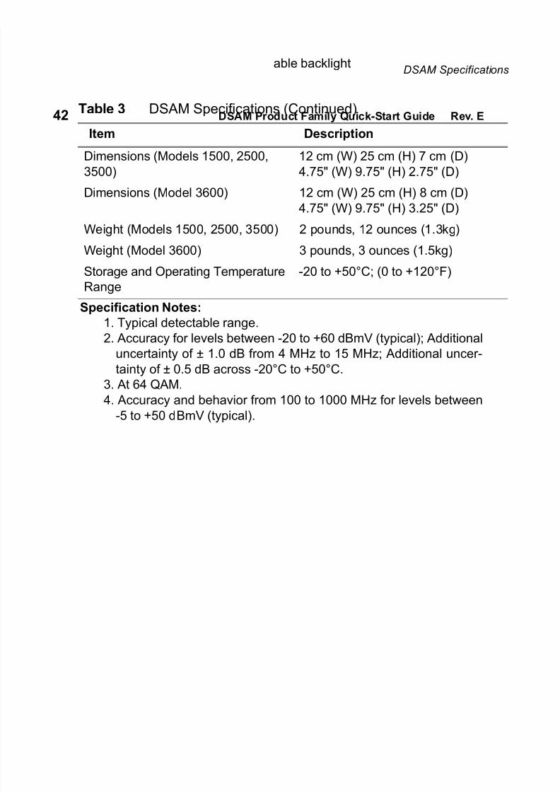
Dimensions (Models 1500, 2500,
3500)
12 cm (W) 25 cm (H) 7 cm (D)
4.75" (W) 9.75" (H) 2.75" (D)
Dimensions (Model 3600) 12 cm (W) 25 cm (H) 8 cm (D)
4.75" (W) 9.75" (H) 3.25" (D)
Weight (Models 1500, 2500, 3500) 2 pounds, 12 ounces (1.3kg)
Weight (Model 3600) 3 pounds, 3 ounces (1.5kg)
Storage and Operating Temperature
Range
-20 to +50°C; (0 to +120°F)
Specification Notes:1. Typical detectable range.
2. Accuracy for levels between -20 to +60 dBmV (typical); Additional
uncertainty of ± 1.0 dB from 4 MHz to 15 MHz; Additional uncer-
tainty of ± 0.5 dB across -20°C to +50°C.
3. At 64 QAM.
4. Accuracy and behavior from 100 to 1000 MHz for levels between
-5 to +50 dBmV (typical).
Table 3 DSAM Specifications (Continued)
Item Description

7/28/2019 DSAM-2500 Manual2 En
http://slidepdf.com/reader/full/dsam-2500-manual2-en 54/56
Power Component Specifications
44 DSAM Product Family Quick-Start Guide Rev. E
Power Component Specifications
Table 4 Power Component Specifications
Item Description
Charger Module
Input
Operational voltage range 11 to 14VDC (nominal = 12V DC)
Input protection Reverse polarity; ESD
Connector 2.5 mm coaxial
Environmental
Operational temperature range -20 to +50 °C (0 to +120 °F)
Storage temperature range -20 to +80 °C (0 to +176 °F)
High fast-charge inhibit range 60 °C (± 5 °C) (140 °F)
Low fast charge inhibit range 0 °C (± 5 °C) (+32 °F)
Humidity range 0 to 95% RH (non condensing)
Output - NiMH Battery
Battery life 3 hours (typical)
Fast charge rate 1000mA ± 10% @ 7.2V
Maximum charge time Up to 5 hours
Output - Li-Ion Battery
Battery life 4.5 Hours (typical)
Fast charge rate 1000mA ± 10% @ 7.4V
Maximum charge time Up to 6.5 hours
Power Supply Module
Input
AC Input Voltage Range 90 - 264 VAC
AC Input Frequency 47 - 63 Hz
Output
Output Voltage +12VDC
Maximum Load Current 2A

7/28/2019 DSAM-2500 Manual2 En
http://slidepdf.com/reader/full/dsam-2500-manual2-en 55/56

7/28/2019 DSAM-2500 Manual2 En
http://slidepdf.com/reader/full/dsam-2500-manual2-en 56/56
20400 Observation DriveGermantown, Maryland
20876-4023
USA
Acterna is present in more
than 80 countries. To findyour local sales office go to:
www.acterna.com
Worldwide
Headquarters
North America20400 Observation Drive
Germantown, Maryland
20876-4023
USAToll Free: +1 866 228 3762
Tel: +1 301 353 1550Fax: +1 301 444 8468
Regional Sales
Headquarters
Asia Pacific42 Clarendon Street
PO Box 141
South Melbourne
Victoria 3205 Australia
Tel: +61 3 9690 6700Fax: +61 3 9690 6750
Eastern Europe,
Middle East & AfricaElisabethstrasse 36
2500 Baden
Austria
Tel: +43 2252 85 5210
Fax: +43 2252 80 727
1st Neopalimovskiy Per.
© Copyright 2002
Acterna, LLC.
All rights reserved.
Acterna and its logo aretrademarks of Acterna,
LLC. All other trademarksand registered trademarks
are the property of their
Note: Specifications,
terms and conditions
are subject to change
without notice.