Embed Size (px)
Citation preview

ContentProduct description 2Type code 3Technical data 5Diagrams/characteristic curves 6Electrical connection 7Dimensions 8Project planning information 9Information 11Accessories 14Safety Instructions 15
Draft sensorKMB
RE 95170/12.2018Replaced: 11.2017
▶ Force measurement for hitch control and baling presses▶ Measuringranges±25kN … ±160kN▶ Output signal proportional voltage▶ Supplyvoltage5 V/8 … 10 V▶ ProtectionclassuptoIP67/IP69K
Features▶ Force sensor according to category 3 of ISO 730-1
rear-mounted three-point linkage▶ Sensor element with magneto-elastic measurement
principle▶ Integrated electronics▶ Output signal ratiometric and proportional to the force▶ Zero point and sensitivity are calibrated
RE 95170, 12.2018, Bosch Rexroth AG

Product description
Description
The force sensor is constructed as a bearing block. Shear stress arises at the bearing position which is analyzed as a magneto-elasticeffect. Intheunloadedstateasymmetricalmagneticfieldformsbetween the poles due to the primary coil. If tensile or compressive forces are introduced, the magnetic proper-ties of the originally isotropic material change. The magne-ticfieldbecomesasymmetricasaresult.Thisleadstoamagneticpotentialdifferencebetweenthesecondarypoles.Thiscausesamagneticfluxthroughthesecondarycircuitso that a voltage is induced in the secondary coils. Thisvoltageisproportionaltotheforcethatisexerted.Itisamplifiedanrectifiedinanintegratedevaluationcircuit.
The sensor provides a ratiometric voltage (25 % to 75 % of the supply voltage). It is available for various measuring ranges and versions of cable. This sensor is a typical integ-ral part of electro-hydraulic hitch control (EHC). This sensor is intended for being used in agricultural technology.
Functional principle
S
N
S
NA E
AE
AE
bF ≠ O
aF = O
F
1
5
2 3
3
4
1 Primary coil
2 Secondary coil
3 Primary pole area
4 Secondary pole area
5 Steel sleeve
a Symmetricalmagneticfield
b Asymmetricalmagneticfield
Block diagram
321
FU
Supply voltage Usup
Signal voltage Usig
Ground GND
KMB | Draft sensorProduct description
2
Bosch Rexroth AG, RE 95170, 12.2018

Type code
01 02 03 04 05 06 07
KMB / 30
Type
01 Force measurement pin KMB
Load range
02
±25 kN 025
±40 kN 040
±50 kN 050
±60 kN 060
±90 kN 090
±110 kN 110
±150 kN 150
±160 kN 160
Supply voltage
035 ±0.5 V 05
8 V … 12 V 10
Cable versions
04
Cable without protective sheath 1
Cable with protective spiral sheath 2
Cable with protective metal sheath 3
Cable with protective plastic sheath 4
Plug
05AMP plug, 3-pin A
DEUTSCH connector; 3-pin B
Series
06 30
Cable length
07
800 mm 08
965 mm 09
1000 mm 10
1500 mm 15
1600 mm 16
1800 mm 18
2700 mm 27
Draft sensor | KMBType code
3
RE 95170, 12.2018, Bosch Rexroth AG
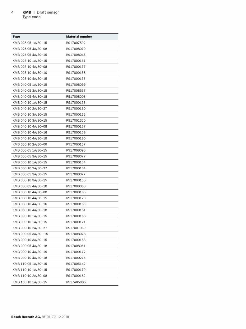
Type Material number
KMB025051A/30–15 R917007592
KMB025054A/30–08 R917008079
KMB025054A/30–15 R917008045
KMB025101A/30–15 R917000161
KMB025104A/30–08 R917000177
KMB025104A/30–10 R917000158
KMB025104A/30–15 R917000175
KMB040051A/30–15 R917008099
KMB040053A/30–15 R917008667
KMB040054A/30–18 R917008003
KMB040101A/30–15 R917000153
KMB040102A/30–27 R917000160
KMB040103A/30–15 R917000155
KMB040103A/30–15 R917001320
KMB040104A/30–08 R917000167
KMB040104A/30–16 R917000159
KMB040104A/30–18 R917000180
KMB050102A/30–08 R917000157
KMB060051A/30–15 R917008098
KMB060053A/30–15 R917008077
KMB060101A/30–15 R917000154
KMB060102A/30–27 R917000164
KMB060053A/30–15 R917008077
KMB060103A/30–15 R917000156
KMB060054A/30–18 R917008060
KMB060104A/30–08 R917000166
KMB060104A/30–15 R917000173
KMB060104A/30–16 R917000165
KMB060104A/30–18 R917000181
KMB090101A/30–15 R917000168
KMB090101A/30–15 R917000171
KMB090102A/30–27 R917001969
KMB090053A/30–15 R917008078
KMB090103A/30–15 R917000163
KMB090054A/30–18 R917008061
KMB090104A/30–15 R917000172
KMB090104A/30–18 R917000275
KMB110051A/30–15 R917005142
KMB110101A/30–15 R917000179
KMB110102A/30–08 R917000162
KMB150101A/30–15 R917A05986
KMB | Draft sensorType code
4
Bosch Rexroth AG, RE 95170, 12.2018

Draft sensor | KMBTechnical data
5
RE 95170, 12.2018, Bosch Rexroth AG
Technical data
Type 025 040 050 060 090 110 150
Load range F ±25 kN ±40 kN ±50 kN ±60 kN ±90 kN ±110 kN ±150 kN
Overload range: standard ±80 kN ±80 kN ±80 kN ±160 kN ±160 kN ±160 kN ±220 kN
Electrically measurable overload +1.2 Fpressure … –1.5 Ftensile
Supply voltage Usup8 V… 10 Vcontrolledvoltage(nodirectsupplyfromthevehicleelectricalsystem(battery)or5±0.5 V
Supply current Isup< 100 mAat8 V … 10 V; < 50 mAat5±0.5 V
Signal voltage Usig25% … 75%Usupat8 V… 10 V; 15% … 85%Usupat5±0.5 V
Load resistance ≥ 10 kΩ
Characteristic curve 1 1 1 2 2 2 2
Hysteresis Seeofferdrawings
Operating temperature range -35 °C … +85 °C
Storage temperature range -40 °C … +125 °C(permanent);+130 °C(max. 2 hrs)
Type of protec-tion with instal-led mating con-nector
AMP IP67andIP69K
DEUTSCH IP66K
Vibrationalload 24 g
Mating connector 3-pin connector with single-wire seal
Electromagnetic compatibility
ISO 11452-5 2002-04;1 MHz … 2 GHz 150 V/m ≤ ±0.5% Usup

KMB | Draft sensorDiagrams/characteristiccurves
6
Bosch Rexroth AG, RE 95170, 12.2018
Diagrams/characteristic curves
Characteristic curve 1 (load range up to 50 kN or 5 V versions)
100%
100%
Usig
Characteristic with increasing loading
Hysteresis, typical ±0.01 Usup
Characteristic with decreasing loading
FPressureFTensile
Characteristic curve 2 (load range from 60 kN)
100%
100%
Usig
Characteristic with increasing loading
Hysteresis, typical ±0.005 Usup
Characteristic with decreasing loading
FPressureFTensile

Draft sensor | KMBElectrical connection
7
RE 95170, 12.2018, Bosch Rexroth AG
Electrical connection
Plug
AMP Pin Assignment
[mm]
25–0
.5
15–0.5
1
2
3
Connecting UsupwithGNDwillcauseashort-circuit.Theshort-circuitcurrentmustnotexceed1A.Therefore,thecurrentinthesystemmustbelimited.
Pin Connection
1 Weight GND
2 Signal voltage Usig
3 Supply voltage Usup
DEUTSCH Pin Assignment
1
2
3
Connecting UsupwithGNDwillcauseashort-circuit.Theshort-circuitcurrentmustnotexceed1A.Therefore,thecurrentinthesystemmustbelimited.
Pin Connection
1 Supply voltage Usup
2 Signal voltage Usig
3 Weight GND

KMB | Draft sensorDimensions
8
Bosch Rexroth AG, RE 95170, 12.2018
Dimensions
[mm]
8.2–0.5
L*±20
74±3
Ø37
–0.4
2–0
.17
158+1.5
10–1 +1
30°
24–0.5
15+0.2+0.4
+0.5
⌀5
39–0.8+0.8
10–0.5+0.5
+0.5
AMP
DEUTSCH
Protection cap for mating connector
Measurement zone
* See ordering code for cable length

Draft sensor | KMBProject planning information
9
RE 95170, 12.2018, Bosch Rexroth AG
Project planning information
Cable versions
Cable without protective sheath
[mm]
L±20
74±3
⌀15
±0.5 ⌀
5
8.2±0.5
Protection cap for mating connector
Cable with protective spiral sheath
[mm]
8.2±0.5 L±20
74±3
⌀15
±0.5 ⌀
5
⌀14
±1
Protection cap for mating connector
Cable with protective metal sheath
[mm]
⌀10
8.2±0.5
800±20
L±20
1.5
Ø5
⌀15
±0.5
74±3
[inch]
Protection cap for mating connectorFitting (WAF 13), rotating
Metal protective sleeve, movable
A-thread, Pg 7 (WAF 15)

KMB | Draft sensorProject planning information
10
Bosch Rexroth AG, RE 95170, 12.2018
Cable with protective plastic sheath
[mm]
74±3
8.2±0.5 L±20
⌀10 ⌀5
⌀15
±0.5
Protection cap for mating connector
Installation instructions
[mm]
33B
B
B-B
▶ See installation drawing Y 830 304 223 to avoid measu-rement uncertainties
▶ Definedforceapplication,e.g.ball-typenipple▶ Float mounting in radial direction with key plate

Draft sensor | KMBInformation
11
RE 95170, 12.2018, Bosch Rexroth AG
Information
Manufacturer confirmation of MTTFD values
The component was developed and series produced before the validity of the currently applicable machinery directive 2006/42/ECandtheharmonizedENISO13849standard. TheKMB3componentisnotasafetycomponentinthesenseofDirectiveonMachinery2006/42/ECandhasnotbeendevelopedaccordingtoISO13849:2008. The MTTFD value was determined in accordance with ISO 13849-1:2008-12,AppendixD,PartsCountMethod,and
thespecifiedtemperatureprofilesbelowforthecompo-nent. The MTTFDvalueforKMB3is113years.
Operating time percentage [%] Ambient temperature of control unit [°C]
0 10
0 30
0 40
0 50
0 60
0 70
0 80
100 85
0 100
The product meets the basic and proven safety principles asperISO13849-2:2008-09astheyapplytotheproduct.

KMB | Draft sensorInformation
12
Bosch Rexroth AG, RE 95170, 12.2018
Bewertung der Sicherheitsprinzipien
Chapter General safety princi-ples Comment Technology Area of use Implemented in product
D.1.6
Application of the princi-ple of energy separation (GS-BGIA-M13:off-loadcurrent principle, spring, return spring)
A safe condition is achieved by separating all important equip-ment from the energy source, e.g. by using a normally closed (NC) contact for inputs (contact and position switches) and a normal-ly open (NO) contact for relays [seealsoEN292-2:1991(ISO/TR12100-2:1992),3.7.1].Therecanbeexceptionsinsomecases,e.g.if a failure of the electrical supply represents an additional hazard. Time-delaying functions may be necessary to ensure that a safe condition of the system is achieved [seeEN60204-1:1997(IEC60204-1:1997),9.2.2]
Electrical system Components
When the energy supply is discon-nected, the sensor stops transmit-ting. There is no appreciable capa-citance,soshut-offtakeslessthan1 ms. Higher-level system must detect a cable break. A fault in the electronics that results in a plausible value is not detected.
D.1.7 Suppression of voltage peaks
A mechanism for suppressing voltage peaks (RC element, diode, varistor) should be used parallel to the applied load but not parallel to the contacts. NOTE:Theswitch-offtimeisincrea-sed by a diode.
Electrical system Components
Measurement of radiated emissi-ons was not carried out. The result is below the values that the stan-dards require. The operating para-metersdefinedinsideTKUmustbeensured by the higher-level system.
D.1.12
Protectionfromunex-pected restarting after restoring the energy supply
Avoidingunexpectedstart-up,e.g. after restoring the energy supply[seeEN292-2:1991(ISO/TR12100-2:1992),3.7.2,EN1037(ISO14118),EN60204-1(IEC60204-1)].Specialapplications,e.g. maintaining the energy for clamping devices or securing a position, need to be considered separately.
Electrical system Components
Assuming that the sensor is supplied with a supply voltage ac-cordingtothespecification,ara-tiometric output signal is present. The higher-level system (control unit) must always ensure that the sensor signal is interpreted cor-rectly.
List of the safety principles that must be to take into account in the higher-level system.

Draft sensor | KMBInformation
13
RE 95170, 12.2018, Bosch Rexroth AG
Chapter Well-tried safety prin-ciples Comment Technology Area of use Implemented in product
A.2.2Use of components with adefinedfailurebeha-vior
The most frequent failure beha-vior of a component is known in advance and is always the same, seeEN292-2:1991(ISO/TR12100-2:1992),3.7.4.
Mechanical system Components
If the sensor is operated outside thespecification,thiscanresultin a zero shift or breakage. The higher-level system must detect this and evaluate it.
D.3.5 Limitation of electrical parameters
Limiting of the voltage, current, energy or frequency to avoid an unsafe status, e.g. by torque limit-ation,offset/time-limitedrunningand reduced speed.
Electrical system Components
The upper and lower limit of the supplyvoltagearedefined.Outsi-de of these limits, the sensor rea-ches a clamping voltage that the higher-level system must interpret. In general, the higher-level system must be able to interpret the ratio-metric signal. From4.2Vto18V,thesensorworks on a ratiometric basis. Above and below the voltage limit, the output voltage becomes zero and is detected by the control unit as a cable break.
D.3.8 State switchover in event of failure
Ifpossible,allmechanisms/circuitsshould transition to a safe state or be safe to operate.
Electrical system Components
From4.2Vto18V,thesensorworks on a ratiometric basis. Abo-ve and below the voltage limit, the output voltage becomes zero and is detected by the control unit as a cable break. If the bolt is operated outsidethemechanicalspecificati-on, this can result in a zero shift or breakage. The higher-level system must detect faulty operating condi-tions of the sensor, and appropria-teremediesmustbedefinedandimplemented.
D.2.9 Multiplication of parts
Reduction in the impact of defects by using several parts of the same type;forexample,adefectthatoc-curs in one spring (of many) does not lead to a dangerous condition.
Mechanical system Components
Irrelevant for components, since the only mechanical part of the bolt itself is known (applica-tion-specifically)andthestatusorientation is known in the case of failures, see D.3.8.
D.3.9 Directed failure
If it is possible to implement, com-ponents or systems should be used whose types of failure are known in advance[seeEN292-2:1991(ISO/TR12100-.2:1992),3.7.4].
Electrical system Components
From4.2Vto18V,thesensorworks on a ratiometric basis. Above and below the voltage limit, the output voltage becomes zero and is detected by the control unit as a cable break. The higher-level system must detect faulty opera-ting conditions of the sensor, and appropriate remedies must be de-finedandimplemented.
List of the safety principles that must be to take into account in the higher-level system.

14
Bosch Rexroth AG, RE 95170, 12.2018
Accessories
AMP mating connector R9170005151)
Designation Number Ordering details
Housing 1 19284025792)
Protective cap 1 12807030222)
Contacts 3 9299393)
Single-wire seal (wire size 0.5 … 1 mm²)
3 828905-13) atFLKcabletype
3 828904-13) atFLKr,FLXcable
1) The mating connector is not included in the scope of delivery.2) Available from Bosch3) Available from AMP
DEUTSCH mating connector1
Designation Ordering details
Plug connection DEUTSCH DT 04-3P2)
Wedge locking DEUTSCH W 3P2)
Contacts DEUTSCH0460-202-161412)
1) The mating connector is not included in the scope of delivery.2) Available from DEUTSCH
KMB | Draft sensorAccessories

15
RE 95170, 12.2018, Bosch Rexroth AG
Draft sensor | KMBSafety Instructions
Safety Instructions
General instructions▶ Beforefinalizingyourdesign,requestabindinginstalla-
tion drawing.▶ The proposed circuits do not imply any technical liability
forthesystemonthepartofBoschRexroth.▶ Openingthesensororcarryingoutmodificationstoor
repairsonthesensorisprohibited.Modificationsorrepairs to the wiring could lead to dangerous malfunc-tions.
▶ Thesensormayonlybeassembled/disassembledinadeenergized state.
▶ Onlytrainedandexperiencedspecialistswhoareade-quately familiar with both the components used and the complete system should implement system develop-ments or install and commission electronic systems for controlling hydraulic drives.
▶ When commissioning the sensor, the machine may pose unforeseen hazards. Before commissioning the system, you must therefore ensure that the vehicle and the hydraulic system are in a safe condition.
▶ Make sure that nobody is in the machine’s danger zone.▶ Do not use defective components or components not
in proper working order. If the sensor should fail or demonstrate faulty operation, it must be replaced.
▶ Despite every care being taken when compiling this document, it is not possible to consider all feasible applications.Ifinstructionsforyourspecificapplicationaremissing,youcancontactBoschRexroth.
▶ The use of sensors by private users is not permitted, since these users do not typically have the required level ofexpertise.
Notes on the installation location and position▶ Do not install the sensor close to parts that generate
considerableheat(e.g.,exhaust).▶ Linesaretoberoutedwithsufficientdistancefromhot
or moving vehicle parts.▶ Asufficientdistancetoradiosystemsmustbemaintai-
ned.
▶ Before electric welding and painting operations, the sen-sor must be disconnected from the power supply and the sensor connector must be removed.
▶ Cables/wiresmustbesealedindividuallytopreventwater from entering the sensor.
Notes on transport and storage▶ Pleaseexaminethesensorforanydamagewhichmay
have occurred during transport. If there are obvious signs of damage, please inform the transport company andBoschRexrothimmediately.
▶ If it is dropped, the sensor must not be used any longer, as invisible damage could have a negative impact on reliability.
Notes on wiring and circuitry▶ Lines to the sensors must be designed so that they are
as short as possible and shielded. The shielding must be connected to the electronics on one side or to the machine or vehicle ground via a low-resistance connec-tion.
▶ The sensor mating connector must only be plugged and unplugged when it is in a deenergized state.
▶ The sensor lines are sensitive to spurious interference. For this reason, the following measures should be taken when operating the sensor:– Sensor lines should be attached as far away as pos-
sible from large electric machines.– Ifthesignalrequirementsaresatisfied,itispossible
toextendthesensorcable.
▶ Lines from the sensor to the electronics must not be routed close to other power-conducting lines in the machine or vehicle.
▶ Thewiringharnessshouldbefixatedmechanicallyintheareainwhichthesensorisinstalled(spacing <150 mm).Thewiringharnessshouldbesecuredsothatin-phaseexcitationwiththesensoroccurs(e.g.atthesensor mounting point).
▶ If possible, lines should be routed in the vehicle interior. If the lines are routed outside the vehicle, make sure thattheyaresecurelyfixed.
▶ Lines must not be kinked or twisted, must not rub against edges and must not be routed through sharp-ed-ged ducts without protection.

16
Bosch Rexroth AG, RE 95170, 12.2018
Intended use▶ The sensor is designed for use in mobile working machi-
nesprovidednolimitations/restrictionsaremadetocertain application areas in this data sheet.
▶ Operation of the sensor must generally occur within the operatingrangesspecifiedandapprovedinthisdatasheet, particularly with regard to voltage, temperature, vibration, shock and other described environmental influences.
▶ Useoutsideofthespecifiedandapprovedboundaryconditionsmayresultindangertolifeand/orcausedamage to components which could result in sequential damage to the mobile working machine.
▶ Seriouspersonalinjuryand/ordamagetopropertymayoccur in case of non-compliance with the appropriate regulations.
Improper use▶ Any use of the sensor other than that described in the
chapter "Intended use" is considered to be improper.▶ Useinexplosiveareasisnotpermitted.▶ Damageswhichresultfromimproperuseand/orfrom
unauthorized, unintended interventions in the device not described in this data sheet render all warranty and liability claims with respect to the manufacturer void.
Use in safety-related functions▶ The customer is responsible for performing a risk analy-
sis of the mobile working machine and determining the possible safety-related functions.
▶ In safety-related applications, the customer is respon-sible for taking proper measures to ensure safety (sen-
sor redundancy, plausibility check, emergency switch, etc.).
▶ Product data that is required to assess the safety of the machine is included in this data sheet.
Further information▶ Further information about the sensor can be found at
www.boschrexroth.de/mobilelektronik.▶ The sensor must be disposed of in accordance with the
national regulations of the country in which it is used.
KMB | Draft sensorSafety Instructions
Bosch Rexroth AGRobert-Bosch-Straße 271701 SchwieberdingenGermanyServiceTel. [email protected]
© Bosch Rexroth AG 2018.Allrightsreserved,alsoregardinganydisposal,exploitation,reproduction,editing,distribution,aswellasintheeventofapplications for industrial property rights. Thedataspecifiedaboveonlyservetodescribetheproduct.Nostatementsconcerning a certain condition or suitability for a certain application can be derived from our information. The information given does not release the userfromtheobligationofownjudgmentandverification.Itmustberemem-bered that our products are subject to a natural process of wear and aging.