Embed Size (px)
Citation preview

DKG-705 User Manual V-02-21 (02.09.2010)
Electronics Ltd.
[email protected] http://www.datakom.com.tr
Tel: +90-216 466 84 60 Fax: +90-216 364 65 65
DKG-705 AMF, PARALLEL TO MAINS AND DUAL GENSET SYNCHRONIZATION UNIT
WITH J1939 INTERFACE
STANDARD FEATURES Automatic mains failure J1939 engine monitoring and control port Various engine brands and models available Engine control Generator protection Built in alarms and warnings True RMS measurements Complete genset power measurements Complete mains power measurements Synchroscope Governor and AVR control interfaces No break transfer & no break load test Soft transfer with ramp control Single genset power export to mains Single genset peak lopping (peak shaving) Dual genset synchronization & load sharing Dual genset soft transfer to / from mains KW/KVAr load control G-59 mains protections Battery backed-up real time clock Daily, weekly, monthly exerciser Remote start operation capability Gas engine support Mains simulation input Engine Idle speed control Load shedding Periodic maintenance request indicator Event logging with time stamp Statistical counters
Weekly operation schedule programs Field adjustable parameters RS-232 serial port Upgrade software downloadable from serial port Free MS-Windows Remote monitoring SW: -local, LAN, IP and modem connection -monitoring, download of parameters -download of software updates -modem networking GSM SMS message sending on fault GSM and PSTN modem calls on fault MODBUS communications LCD display 4 lines by 20 characters Dual language support Output expansion capability Configurable analogue inputs: 4 Configurable digital inputs: 8 Configurable relay outputs: 7 Survives cranking dropouts Sealed front panel (IP65) Plug-in connection system for easy replacement
OPTIONAL FEATURES Internal modem (9600bps) External DC voltage measurement External DC voltage based genset operation Internal buzzer

DKG-705 User Manual V-02-21 (02.09.2010)
- 2 -
TABLE OF CONTENTS
Section 1. INSTALLATION
1.1. Introduction to the Control Panel 1.2. Mounting the Unit 1.3. Wiring the Unit
2. INPUTS AND OUTPUTS 3. DISPLAYS
3.1. Led Displays 3.2. Digital Display 3.3. Service Request Display
4. ALARMS 4.1. Shutdown Alarms
4.2. Load Dump Alarms 4.3. Warnings
5. MODES OF OPERATION 5.1. External switching of the operation mode 5.2. Remote start operation 5.3. Mains Simulation 6. SYNCHRONIZING WITH MAINS 6.1 Governor Control 6.2. AVR Control 7. LOAD TRANSFER MODES 7.1 Transfer with Interruption 7.2 No Break Transfer 7.3 Soft Transfer 8. PARALLELING WITH MAINS: 8.1 Power Export to Mains 8.2 Peak Lopping 9. DUAL GENSET PARALLEL OPERATION 10. PROTECTION FUNCTIONS FOR PARALLEL WITH MAINS 11. LOAD SHEDDING / DUMMY LOAD 12. WEEKLY OPERATION SCHEDULE 13. BUILT-IN EXERCISER 14. EVENT LOGGING 15. STATISTICAL COUNTERS 16. MAINTENANCE 17. REMOTE MONITORING AND PROGRAMMING 18. MODEM OPERATION 18.1. Optional Internal Modem 19. GSM SMS SENDING 20. J1939 ENGINE MONITORING AND CONTROL PORT 21. MODBUS COMMUNICATION 22. OTHER FEATURES 22.1. Dual Genset Intermittent Operation 22.2. Engine heating operation 22.3. Engine Idle Speed Operation 22.4. Fuel Pump Control 22.5. Optional External DC Operation (fuel optimized operation) 22.6. Dual Language Support 22.7. Gas Engine Control 23. PROGRAMMING 24. TROUBLESHOOTING 25. DECLARATION OF CONFORMITY

DKG-705 User Manual V-02-21 (02.09.2010)
- 3 -
26. TECHNICAL SPECIFICATIONS 27. CONNECTION DIAGRAM
1. INSTALLATION
1.1 Introduction to the Control Panel
The DKG-705 is a control and protection unit used in gensets. The 4 lines by 20 characters LCD
display allows the visualization of many measured parameters. The unit is designed to provide user
friendliness for both the installer and the user. Programming is usually unnecessary, as the factory settings
have been carefully selected to fit most applications. However programmable parameters allow the
complete control over the generating set. Programmed parameters are stored in a Non Volatile Memory
and thus all information is retained even in the event of complete loss of power.
The measurable parameters are:
Mains voltage phase R to neutral Mains voltage phase S to neutral Mains voltage phase T to neutral Mains voltage phase R-S Mains voltage phase S-T Mains voltage phase T-R Mains current phase R (optional) Mains current phase S (optional) Mains current phase T (optional) Mains frequency Mains KW phase R (optional) Mains KW phase S (optional) Mains KW phase T (optional) Mains KVA phase R (optional) Mains KVA phase S (optional) Mains KVA phase T (optional) Mains KVAr phase R (optional) Mains KVAr phase S (optional) Mains KVAr phase T (optional)
Mains cosΦ phase R (optional)
Mains cosΦ phase S (optional)
Mains cosΦ phase T (optional) Mains total KW (optional) Mains total KVA (optional) Mains total KVAr (optional)
Mains total cosΦ (optional)
Gen voltage phase U to neutral Gen voltage phase V to neutral Gen voltage phase W to neutral Gen voltage phase U-V Gen voltage phase V-W Gen voltage phase W-U Gen current phase U Gen current phase V Gen current phase W Gen frequency Gen KW phase U Gen KW phase V Gen KW phase W Gen KVA phase U Gen KVA phase V Gen KVA phase W Gen KVAr phase U Gen KVAr phase V Gen KVAr phase W
Gen cosΦ phase U
Gen cosΦ phase V
Gen cosΦ phase W Gen total KW Gen total KVA Gen total KVAr
Gen total cosΦ Synchronoscope phase angle Voltage match U-R Battery voltage, Engine RPM Coolant temperature Oil pressure Oil temperature Fuel level

DKG-705 User Manual V-02-21 (02.09.2010)
- 4 -
1.2 Mounting the Unit
The unit is designed for panel mounting. The user should not be able to access parts of the unit
other than the front panel.
Mount the unit on a flat, vertical surface. The unit fits into a standard panel meter opening of 188x140
millimeters. Before mounting, remove retaining steel springs from the unit, then pass the unit through the
mounting opening. The unit will be maintained in its position by the steel springs.
The DKG-705 is factory set for 24V-DC operation. If the unit is used in a 12V-DC system, the 12V
jumper terminals must be short-circuited.
Do not operate a 12V-DC unit with a 24V-DC system. This may cause the destruction of the unit. Always disconnect the voltage selector jumper of a stocked unit.
The engine body must be grounded for correct operation of the unit. Otherwise incorrect voltage and
frequency measurements may occur, resulting in faulty operation of the genset.
The output of the current transformers shall be 5 Amperes. The input current rating of the current
transformers may be selected as needed (between 50/5 and 5000/5 amps). Current transformer outputs shall
be connected by separate cable pairs from each transformer, to related DKG-705 inputs. Never use common
terminals or grounding. The power rating of the transformer should be at least 5 Watts. It is recommended to
use 1% precision transformers.
If analogue sensors (e.g. temperature, oil pressure, oil temperature or fuel level) are connected to
DKG-705, it is not possible to use auxiliary displays. If temperature or oil pressure displays are already present
on the generator control panel, do not connect the sensors to the DKG-705. The unit is factory programmed
for VDO type sensors. However if a different type of sensor is to be used, it is possible to recalibrate the unit.
The calibration process will be explained later in this document. The programmable digital inputs are compatible with both ‘normally open’ and ‘normally closed’ contacts, switching either to BAT- or BAT+.
The charge alternator connection terminal provides also the excitation current, thus it is not necessary
to use an external charge lamp.

DKG-705 User Manual V-02-21 (02.09.2010)
- 5 -
1.3 Wiring the Unit
WARNING: THE UNIT IS NOT FUSED. Use external fuses for Mains phases: R-S-T
Generator phase: U-V-W Battery positive: BAT(+).
Install the fuses as nearly as possible to the unit in a place easily accessible for the user.
The fuse rating should be 6 Amps.
WARNING: ELECTRICITY CAN KILL ALWAYS disconnect the power BEFORE connecting the unit.
1) ALWAYS remove the plug connectors when inserting wires with a screwdriver.
2) ALWAYS refer to the National Wiring Regulations when conducting installation.
3) An appropriate and readily accessible set of disconnection devices (e.g.
automatic fuses) MUST be provided as part of the installation.
4) The disconnection device must NOT be fitted in a flexible cord.
5) The building mains supply MUST incorporate appropriate short-circuit backup
protection (e.g. a fuse or circuit breaker) of High Breaking Capacity (HBC, at
least 1500A).
6) Use cables of adequate current carrying capacity (at least 0.75mm2) and
temperature range.

DKG-705 User Manual V-02-21 (02.09.2010)
- 6 -
2. INPUTS AND OUTPUTS
12V JUMPER: When this jumper is placed, 12V-DC operation is selected. Do not operate a 12V-DC unit with
a 24V-DC system. This may cause the destruction of the unit. Always disconnect the voltage selector jumper
of a stocked unit.
RS-232 SERIAL PORT: This connector provides serial data input and output for various purposes like
software update, remote monitoring, remote control, remote programming, etc. EXTENSION CONNECTOR (OPTIONAL): This connector is intended for the connection of input and output
extension modules. The optional relay extension module provides 8 programmable 16A relay outputs. The
DKG-705 allows the use of up to 2 I/O extension modules.
Term Function Technical data Description
1 GENERATOR CONTACTOR Relay output, 10A-AC This output provides energy to the generator
contactor. If the generator phases do not have
acceptable voltage or frequency values, the
generator contactor will be de-energized. In
standard genset applications, in order to
provide extra security, the normally closed
contact of the mains contactor should be serially connected to this output. In ‘no break transfer’ or ‘parallel with mains’
applications, this output will drive directly the
generator contactor.
2 U Generator phase
inputs, 0-300V-AC Connect the generator phases to these inputs.
The generator phase voltages upper and
lower limits are programmable. 3 V
4 W
5 GENERATOR NEUTRAL Input, 0-300V-AC Neutral terminal for the generator phases.
6 MAINS NEUTRAL Input, 0-300V-AC Neutral terminal for the mains phases.
7 T Mains phase inputs,
0-300V-AC Connect the mains phases to these inputs.
The mains voltages upper and lower limits are
programmable. 8 S
9 R
10 MAINS CONTACTOR Relay output, 10A-AC This output provides energy to the mains
contactor. If the mains phases do not have
acceptable voltage or frequency values, the
mains contactor will be de-energized. In
standard genset applications, in order to
provide extra security, the normally closed
contact of the generator contactor should be serially connected to this output. In ‘no break transfer’ or ‘parallel with mains’
applications, this output will drive directly the
mains contactor.

DKG-705 User Manual V-02-21 (02.09.2010)
- 7 -
Term Function Technical data Description
11 CURR_W+ Current transformer
inputs, 5A-AC
Connect the generator current transformer
terminals to these inputs. Do not connect the
same current transformer to other units than
DKG-705 otherwise a unit fault will occur.
Connect each terminal of the transformer to
the unit’s related terminal. Do not use
common terminals. Do not use grounding.
Correct polarity of connection is vital. If the
measured power is negative, then change the
polarity of each 3 current transformers. The
rating of the transformers should be the same
for each of the 3 phases. The secondary
winding rating shall be 5 Amperes. (For ex.
200/5 Amps).
12 CURR_W-
13 CURR_V+
14 CURR_V-
15 CURR_U+
16 CURR_U-
17 COOLANT TEMP. SENSOR Input, 0-5000 ohms Analogue temperature sensor connection. Do
not connect the sensor to other devices.
18 OIL PRESSURE SENSOR Input, 0-5000 ohms Analogue oil pressure sensor connection. Do
not connect the sensor to other devices.
19 FUEL LEVEL SENSOR Input, 0-5000 ohms Analogue fuel level sensor connection. Do not
connect the sensor to other devices.
20 OIL TEMP. SENSOR Input, 0-5000 ohms Analogue oil temperature sensor connection.
Do not connect the sensor to other devices.
Term Function Technical data Description
21 PROGRAM LOCK Digital input This input is used to prevent unwanted
modification to programmed values. If this
input is left open, program values can be
modified via the front panel buttons, but if this
input is connected to battery- it will not be
possible to change the program values.
22 DIGITAL INPUT-7 Digital inputs These inputs have programmable functions,
selectable from a list via the program menu.
Each input may be driven by a ‘normally
closed’ or ‘normally open’ contact, switching
either battery+ or battery-. The effect of the
switch is also selectable from a list. See
PROGRAMMING section for more details.
23 DIGITAL INPUT-6
24 DIGITAL INPUT-5
25 DIGITAL INPUT-4
26 DIGITAL INPUT-3
27 DIGITAL INPUT-2
28 DIGITAL INPUT-1
29 DIGITAL INPUT-0
30 GROUND O VDC Power supply negative connection.
31 CHARGE Input and output Connect the charge alternator’s D+ terminal
to this terminal. This terminal will supply the
excitation current and measure the voltage of
the charge alternator.

DKG-705 User Manual V-02-21 (02.09.2010)
- 8 -
Term Function Technical data Description
32 RELAY-6 (FUEL RELAY) Output 10A/28VDC This relay is normally used for fuel solenoid control. It is internally connected to terminal 31
for supplying the charge alternator’s excitation
current.
33 RELAY-2 (CRANK RELAY) Output 10A/28VDC This relay has programmable function,
selectable from a list. However it is generally
used as engine crank output.
34 BATTERY POSITIVE +12 or 24VDC The positive terminal of the DC Supply shall
be connected to this terminal. The unit
operates on both 12V and 24V battery
systems, depending on the voltage selection
jumper. Do not operate a 12V-DC unit with a
24V-DC system. This may cause the
destruction of the unit. Always disconnect
the voltage selector jumper of a stocked unit.
35 RELAY-7 (STOP RELAY) Output 10A/28VDC These relays have programmable functions,
selectable from a list. 36 RELAY-1 (PREHEAT) Output 10A/28VDC
37 RELAY-3 (ALARM RELAY) Output 10A/28VDC
Term Function Technical data Description
38 CURR_R+ Current transformer
inputs, 5A-AC
Connect the mains current transformer
terminals to these inputs. Do not connect the
same current transformer to other units than
DKG-705 otherwise a unit fault will occur.
Connect each terminal of the transformer to
the unit’s related terminal. Do not use
common terminals. Do not use grounding.
Correct polarity of connection is vital. If the
measured power is negative, then change the
polarity of each 3 current transformers. The
rating of the transformers should be the same
for each of the 3 phases. The secondary
winding rating shall be 5 Amperes. (For ex.
200/5 Amps).
39 CURR_R-
40 CURR_S+
41 CURR_S-
42 CURR_T+
43 CURR_T-
Term Function Technical data Description
44 MAGNETIC PICKUP Inputs, 0.5-70V
0-20KHz
Connect the magnetic pickup signal to these
inputs. 45 MAGNETIC PICKUP
46 AVR CONTROL Output,
isolated resistor,
300-100,000 ohms.
AVR voltage control outputs. Connect to the
external adjust potentiometer terminals of the
AVR. The polarity is not important. 47 AVR CONTROL
48 GOVERNOR CONTROL Output, 0-10VDC Connect this output to the terminal ‘J’ or ‘EXT’
of the speed governor.
51 J1939-H Canbus-H connection Connect this terminal to the CAN-H of the
ECU unit.
52 J1939-L Canbus-L connection Connect this terminal to the CAN-L of the ECU
unit.
56 INTERNAL MODEM - TIP Optional telephone
line connection
Connect this terminal to the telephone line.
The polarity is not important.
57 INTERNAL MODEM - RING Optional telephone
line connection
Connect this terminal to the telephone line.
The polarity is not important.
59 EXTERNAL DC - Optional input
0 to -100VDC
Connect this terminal to the negative terminal
of the DC voltage input.
60 EXTERNAL DC + Optional input
0 to -100VDC
Connect this terminal to the positive terminal
of the DC voltage input.

DKG-705 User Manual V-02-21 (02.09.2010)
- 9 -
3. DISPLAY
3.1 Led Displays
The DKG-705 has 12 leds, divided in 3 groups: -Group_1: Operating mode: This group indicates the genset function.
-Group_2: Mimic diagram: This group indicates the current status of the mains and genset
voltages and contactors. -Group_3: Warnings and alarms: This group indicates the existency of abnormal conditions
encountered during operation.
Function Color Description
MAINS ON Green The LED will turn on when all 3 mains phase voltages
and the mains frequency are within the limits.
MAINS OFF Red The LED will turn on when at least one of the mains
phase voltages or the mains frequency are outside
limits.
GENERATOR Yellow The LED will turn on when all 3 generator phase
voltages are within the programmed limits.
LOAD GENERATOR Yellow It turns on when the generator contactor is activated.
LOAD MAINS Green It turns on when the mains contactor is activated.
LOAD TEST Yellow It turns on when the related operation mode is
selected. One of these LEDs is always on and
indicates which operation mode is selected.
If the operation of the genset is disabled by the weekly operation schedule, then the AUTO led will
flash.
TEST Yellow
OFF Green
AUTO Green
ALARM Red It turns on when an engine shutdown or load_dump
condition is occurred.
WARNING Red It turns on when an engine shutdown or load_dump
or warning condition is occurred.
SERVICE REQUEST Red Engine periodic maintenance request indicator. It
turns on when the preset engine hours or time
duration after previous service has elapsed.

DKG-705 User Manual V-02-21 (02.09.2010)
- 10 -
3.2 Digital Display
The digital display is of LCD type, with 4 lines by 20 characters. It shows: -The software version and release date, -The genset status, -Measured parameters, -Alarm information, -Date and time, -Service counters, -Statistical counters, -Logged events, -Program parameters. During power on, the display shows the software version and the release date for 1 seconds. The display has basically two modes: -Normal operation, -Programming mode.
The programming mode will be explained later in this document. The display is driven by a menu system. The display has many different screens, divided into 3
main groups.
The navigation between different screens in a group is made with the MENU button. Holding the MENU button pressed for 1 second makes the display to switch to the next group. During operation, the DKG-705 will switch automatically between different screens, displaying each time the most important screen for the given situation. If an alarm or warning occurs during operation other then programming mode, the display will automatically switch to ALARM LIST position. The MENU button will not allow to switch to other modes. To enable display navigation, press ALARM MUTE button. The display has a backlight illumination feature. The backlight turns on with the depression of any button. It turns off after 1 minute to allow power economy. Also note that the backlight will turn off during engine cranking. Group Screen Description Contents
1 1 Mains parameters Genset status Voltage R (or RS), current R, Mains Frequency Voltage S (or ST), current S Voltage T (or TR), current T
1 2 Mains parameters Genset status Voltage RS (or R), current R, Mains Frequency Voltage ST (or S), current S Voltage TR (or T), current T
1 3 Basic genset parameters Genset status Voltage U (or UV), current U, Genset Frequency Voltage V (or VW), current V, Genset Active Power (KW)
Voltage W (or WU), current W, Genset Power Factor (cosΦ) 1 4 Basic genset parameters Genset status
Voltage UV (or U), current U, Genset Frequency Voltage VW (or V), current V, Genset Active Power (KW)
Voltage WU (or W), current W, Genset Power Factor (cosΦ)
DKG-705 User Manual V-02-21 (02.09.2010)
- 11 -
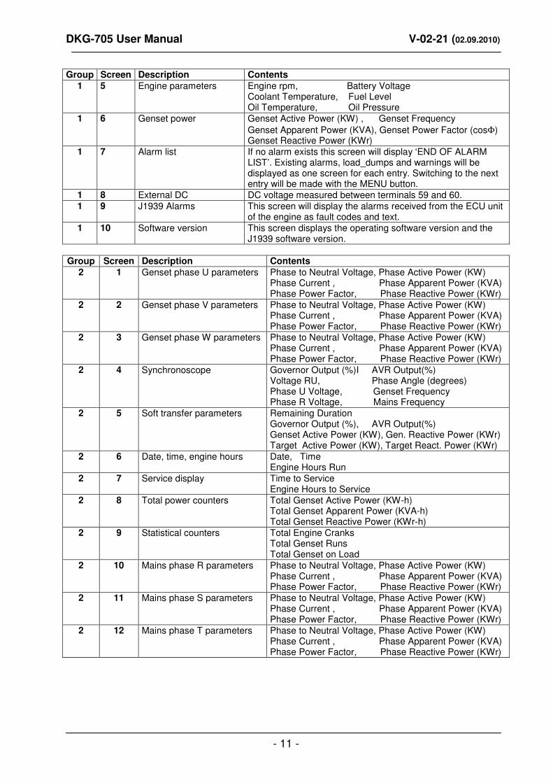
Group Screen Description Contents
1 5 Engine parameters Engine rpm, Battery Voltage Coolant Temperature, Fuel Level Oil Temperature, Oil Pressure
1 6 Genset power Genset Active Power (KW) , Genset Frequency
Genset Apparent Power (KVA), Genset Power Factor (cosΦ) Genset Reactive Power (KWr)
1 7 Alarm list If no alarm exists this screen will display ‘END OF ALARM LIST’. Existing alarms, load_dumps and warnings will be displayed as one screen for each entry. Switching to the next entry will be made with the MENU button.
1 8 External DC DC voltage measured between terminals 59 and 60. 1 9 J1939 Alarms This screen will display the alarms received from the ECU unit
of the engine as fault codes and text. 1 10 Software version This screen displays the operating software version and the
J1939 software version.
Group Screen Description Contents
2 1 Genset phase U parameters Phase to Neutral Voltage, Phase Active Power (KW) Phase Current , Phase Apparent Power (KVA) Phase Power Factor, Phase Reactive Power (KWr)
2 2 Genset phase V parameters Phase to Neutral Voltage, Phase Active Power (KW) Phase Current , Phase Apparent Power (KVA) Phase Power Factor, Phase Reactive Power (KWr)
2 3 Genset phase W parameters Phase to Neutral Voltage, Phase Active Power (KW) Phase Current , Phase Apparent Power (KVA) Phase Power Factor, Phase Reactive Power (KWr)
2 4 Synchronoscope Governor Output (%)I AVR Output(%) Voltage RU, Phase Angle (degrees) Phase U Voltage, Genset Frequency Phase R Voltage, Mains Frequency
2 5 Soft transfer parameters Remaining Duration Governor Output (%), AVR Output(%) Genset Active Power (KW), Gen. Reactive Power (KWr) Target Active Power (KW), Target React. Power (KWr)
2 6 Date, time, engine hours Date, Time Engine Hours Run
2 7 Service display Time to Service Engine Hours to Service
2 8 Total power counters Total Genset Active Power (KW-h) Total Genset Apparent Power (KVA-h) Total Genset Reactive Power (KWr-h)
2 9 Statistical counters Total Engine Cranks Total Genset Runs Total Genset on Load
2 10 Mains phase R parameters Phase to Neutral Voltage, Phase Active Power (KW) Phase Current , Phase Apparent Power (KVA) Phase Power Factor, Phase Reactive Power (KWr)
2 11 Mains phase S parameters Phase to Neutral Voltage, Phase Active Power (KW) Phase Current , Phase Apparent Power (KVA) Phase Power Factor, Phase Reactive Power (KWr)
2 12 Mains phase T parameters Phase to Neutral Voltage, Phase Active Power (KW) Phase Current , Phase Apparent Power (KVA) Phase Power Factor, Phase Reactive Power (KWr)

DKG-705 User Manual V-02-21 (02.09.2010)
- 12 -
2 13 CANBUS measurements 1 Percent Torque
Percent Load Instant Fuel Economy
2 14 CANBUS measurements 2 Fuel Rate Average Fuel Economy Total Engine Hours
2 15 CANBUS measurements 3 Air Pressure Ambient Air Temp. Air Inlet Temp.
2 16 CANBUS measurements 4 Intake Man1. Temperature Exhaust Gas Temperature Fuel Temperature
2 17 CANBUS measurements 5 Boost Pressure Air Filter Different Crank Case Pressure
2 18 CANBUS measurements 6 Coolant Level Oil Level Coolant Pressure
Group Screen Description Contents
3 1…32 Event logging This group comprises 32 screens, each screen displaying one recorded event, starting from the most recent one.

DKG-705 User Manual V-02-21 (02.09.2010)
- 13 -
3.3 Service Request Display
This led is designed to help the periodic maintenance of the genset to be made consistently.
The periodic maintenance is basically carried out after a given engine hours (for example 200 hours),
but even if this amount of engine hours is not fulfilled, it is performed after a given time limit (for example 1
year).
The SERVICE REQUEST led has no effect on the genset operation. However a warning may be generated based on the program parameter P_642.
The DKG-705 has both programmable engine hours and maintenance time limit. The engine hours is programmable between 0 and 2500 hours with 10-hour steps (P_624), the time limit is programmable between
0 and 2500 days with 10 day steps (P_625). If any of the programmed values is zero, this means that the
parameter will not be used. For example a maintenance period of 0 days indicates that the DKG-705 will
request maintenance only based on engine hours, without time limit. If the engine hours is also selected as 0
hours this will mean that the SERVICE REQUEST display will be inoperative.
The remaining engine hours and the remaining time limit are kept stored in a non-volatile memory and
are not modified by power supply failures. The remaining engine hours and time to service may be checked on
the LCD display. (group_2, screen_7)
When the engine hours OR the time limit is over, the SERVICE REQUEST led (red) will start to flash.
To turn off the led, select programming mode, enter factory password and set the parameter_600 to 1, then
check the remaining time and engine hours to service using group_2, screen_7. Please check also the time and engine hours to service parameters. (P_624 / P_625)
If the program parameter P_642 is set to 1, then a warning will be generated when the service request
occurs. This will enable GSM SMS message sending and modem calls on service request.

DKG-705 User Manual V-02-21 (02.09.2010)
- 14 -
4. ALARMS
Alarms indicate an abnormal situation in the generating set.
The alarms are divided into 3 priority level:
1- SHUTDOWN ALARMS: These are the most important alarm conditions and cause:
- The genset contactor to be released immediately,
- The engine to be stopped immediately,
- The alarm relay output to operate, - The ALARM led to turn on,
- The LCD display to switch to alarm display mode (except when programming).
2- LOAD DUMP ALARMS: These conditions cause:
- The genset contactor to be released immediately,
- The engine to be stopped after the cooldown cycle,
- The alarm relay output to operate, - The ALARM led to turn on,
- The LCD display to switch to alarm display mode (except when programming)
3- WARNINGS: These conditions cause:
- The alarm relay output to operate, - The WARNING led to turn on.
Most of the alarms are of LATCHING type. Even if the alarm condition is removed, the alarms will stay
on and disable the operation of the genset.
The existing alarms may be canceled by pressing one of the operating mode buttons (LOAD TEST /
TEST / OFF / AUTO) or by pressing the ALARM MUTE button twice.
If the ALARM MUTE button is pressed, the alarm relay output will be deactivated; however the
existing alarms will persist and disable the operation of the genset.
Most of the alarms have programmable trip levels. See the programming chapter for settable alarm
limits.
The digital inputs are programmable and may be set to provide a large variety of alarms and warnings.
See the programming chapter for digital input programming.
The alarms may be cancelled either by pressing any of the front panel mode selection buttons or by a
change in external mode force inputs.

DKG-705 User Manual V-02-21 (02.09.2010)
- 15 -
4.1 Shutdown Alarms
Definition Source Description
Low Oil Pressure Switch Digital Input These shutdown alarms are set depending on the digital input settings. The related program parameters are P_700 to P_776. High Eng.Temp.Switch Digital Input
Emergency Stop Digital Input
Low Coolant Level Digital Input
Alternator High Temp. Digital Input
High Oil Temp. Digital Input
Overload Digital Input
Low Fuel Level Digital Input
Battery Charger Fail Digital Input
Battery Charger (load) F. Digital Input
Motion Detector Alarm Digital Input
Earthquake Alarm Digital Input
Spare Alarm 4 Digital Input
Spare Alarm 3 Digital Input
Spare Alarm 2 Digital Input
Spare Alarm 1 Digital Input
Gen Under-Frequency Phase U Set if the genset frequency goes under the Low Frequency Shutdown (P_516) limit for Frequency Timer (P_520) period.
Gen Over Frequency Phase U Set if the genset frequency goes over the High Frequency Shutdown (P_518) limit for Frequency Timer (P_520) period.
High Battery Voltage Battery Set if the battery voltage goes over the High Battery Voltage Shutdown (P_610) limit.
Low Fuel Level Analog In. Set if the fuel level measured from analog input goes under the Low Fuel Level Shutdown (P_608) limit.
High Oil Temperature Analog In. Set if the oil temperature measured from analog input goes over the High Oil Temperature Shutdown (P_606) limit.
High Coolant
Temperature
Analog In. Set if the coolant temperature measured from analog input goes over the High Coolant Temperature Shutdown (P_604) limit.
Low Oil Pressure
Measured
Analog In. Set if the oil pressure measured from analog input goes under the Low Oil Pressure Shutdown (P_602) limit.
Fail To Stop Internal Set if the engine is not stopped before the expiration of the Stop Timer (P_505).
Fail To Start Internal Set if the engine has not started after Start Attempts (P_504)
number of attempts.
Genset Low Voltage U-V-W Set if any of the genset phase voltages goes under the Generator Low Limit (P_514) voltage.
Genset High Voltage U-V-W Set if any of the genset phase voltages goes over the Generator High Limit (P_515) voltage.
Slave Unavailable (dual
genset mode)
Serial
Comm.
Set if a shutdown or load dump alarm has occurred in the slave
genset and Single Genset Load Enable (P_A32) is set to 0.
Gen Phase Sequence
Fail
U-V-W Set if the generator phase sequence is not correct. This alarm may be cancelled also by programming the Ignore Phase Order parameter (P_A06) to 1.
Low Engine Speed Magnetic
Pickup
Set if the engine rpm goes under the Low rpm Shutdown (P_613) limit. If the Crank Teeth Count (P_619) is set to ‘0’, this alarm will
be disabled.
High Engine Speed Magnetic
Pickup
Set if the engine rpm goes over the High rpm Shutdown (P_615) limit. If the Crank Teeth Count (P_619) is set to ‘0’, this alarm will
be disabled.
Communication Lost (dual
genset mode)
Serial
Comm.
Set if the serial communication between Master and Slave gensets is interrupted and Single Genset Load Enable parameter
(P_A32) is set to 0.
J1939 ECU Alarm J1939 Set if the communication between the unit and the ECU is lost.

DKG-705 User Manual V-02-21 (02.09.2010)
- 16 -
4.2 Load Dump Alarms
Definition Source Description
Low Oil Press.Switch Digital Input These load dump alarms are set depending on the digital input settings. The related program parameters are P_700 to P_776. High Eng.Temp.Switch Digital Input
Emergency Stop Digital Input
Low Coolant Level Digital Input
Alternator High Temp. Digital Input
High Oil Temp. Digital Input
Overload Digital Input
Low Fuel Level Digital Input
Battery Charger Fail Digital Input
Battery Charger
(load)Fail
Digital Input
Motion Detector Alarm Digital Input
Earthquake Alarm Digital Input
Spare Alarm 4 Digital Input
Spare Alarm 3 Digital Input
Spare Alarm 2 Digital Input
Spare Alarm 1 Digital Input
Gen Reverse Power Internal Set if the genset consumes active power (KW) from the mains and this power goes over the Reverse Power Load Dump (P_618)
limit.
Gen Excess Power Internal Set if the genset power (KW) supplied to the load goes over the Excess Power Load Dump (P_617) limit for Overcurrent / Excess Power Timer (P_511).
Alternator Overcurrent Internal Set if at least one of the genset phase currents goes over the Overcurrent Limit (P_510) for Overcurrent / Excess Power Timer (P_511).

DKG-705 User Manual V-02-21 (02.09.2010)
- 17 -
4.3 Warnings
Definition Source Description
Low Oil Press.Switch Digital Input These warnings are set depending on the digital input settings. The related program parameters are P_700 to P_776. High Eng.Temp.Switch Digital Input
Emergency Stop Digital Input
Low Coolant Level Digital Input
Alternator High Temp. Digital Input
High Oil Temp. Digital Input
Overload Digital Input
Low Fuel Level Digital Input
Battery Charger Fail Digital Input
Battery Charger (load)
Fail
Digital Input
Motion Detector Alarm Digital Input
Earthquake Alarm Digital Input
Spare Alarm 4 Digital Input
Spare Alarm 3 Digital Input
Spare Alarm 2 Digital Input
Spare Alarm 1 Digital Input
Synchronization Fail Internal Set if the phase and voltage synchronization is not successful before the expiration of Synchronization Fail Timeout (P_A07).
Gen Under-Frequency Phase-U Set if the genset frequency goes under the Low Frequency Warning (P_517) limit for Frequency Timer (P_520) period.
Gen Over-Frequency Phase-U Set if the genset frequency goes over the High Frequency Warning (P_519) limit for Frequency Timer (P_520) period.
High Battery Voltage Internal Set if the battery voltage goes over the High Battery Voltage Warning (P_611) limit.
Low Fuel Level Analog
Input
Set if the fuel level measured from analog input goes under the Low Fuel Level Warning (P_609) limit.
High Oil Temperature Analog
Input
Set if the oil temperature measured from analog input goes over the High Oil Temperature Warning (P_607) limit.
High Coolant
Temperature
Analog
Input
Set if the coolant temperature measured from analog input goes over the High Coolant Temperature Warning (P_605) limit.
Low Oil Pressure
Measured
Analog
Input
Set if the oil pressure measured from analog input goes under the Low Oil Pressure Warning (P_603) limit.
Mains Phase Sequence
Fail
R-S-T Set if the mains phase sequence is not correct and Ignore Phase Order (P_A06) parameter is ‘0’.
Charge Failure Charge
input
Set if the Charge input (terminal_31) is pulled to battery negative
when the engine is running.
Low Battery Voltage Internal Set if the battery voltage goes under the Low Battery Voltage Warning (P_612) limit.
AVR Control Fail Internal Set if the AVR control output has gone to the low or high limit
value for 1 second.
GOV Control Fail Internal Set if the GOV control output has gone to the low or high limit
value for 1 second.
Low Engine Speed Magnetic
Pickup
Set if the engine rpm goes under the Low rpm Warning (P_614) limit. If the Crank Teeth Count (P_619) is set to ‘0’, this warning will
be disabled.
High Engine Speed Magnetic
Pickup
Set if the engine rpm goes over the High rpm Warning (P_616) limit. If the Crank Teeth Count (P_619) is set to ‘0’, this warning will
be disabled.

DKG-705 User Manual V-02-21 (02.09.2010)
- 18 -
Definition Source Description
Parallel Mains Fail Internal This general warning is set if any of the protection functions have detected a mains failure during parallel with mains operation.
Mains Reverse Power Internal In parallel with mains operation and after the parallel check
timeout delay (P_A23) has elapsed, this warning will be set if the
mains power is negative and over the reverse power limit defined in P_A24.
Mains Frequency Fail R In parallel with mains operation and after the parallel check timeout delay (P_A23) has elapsed, this warning will be set if the mains
frequency is out of the limits defined in P_522 and P_523 for 4
consecutive cycles.
No Mains Frequency R In parallel with mains operation and after the parallel check timeout delay (P_A23) has elapsed, this warning will be set if the mains
frequency disappears for more than 2,5 periods.
ROCOF (df/dt) Fail R In parallel with mains operation and after the parallel check timeout delay (P_A23) has elapsed, this warning will be set if the mains
frequency change exceeds the limit defined in P_A25 for 4
consecutive cycles.
Vector Shift (df/dt) Fail R In parallel with mains operation and after the parallel check timeout delay (P_A23) has elapsed, this warning will be set if the phase of
the mains measured on last 2 cycles jumps over the limit defined in P_A26 on the phase measured on last 4
th and 5
th period.
Communication Lost
(dual genset mode)
Serial
Comm.
Set if the serial communication between Master and Slave gensets is interrupted and Single Genset Load Enable parameter (P_A32)
is set to 1.
J1939 ECU Warning J1939 Set if a fault code is received from the ECU of the engine.
Genset on Load Internal If P_641=1 this warning is set when the load is transferred to the
genset.
Mains on Load Internal If P_641=1 this warning is set when the load is transferred to the
mains.
Service Request Internal If P_642=1 this warning is set when the service request led turns on.
DKG-705 User Manual V-02-21 (02.09.2010)
- 19 -
5. MODES OF OPERATION
The modes of operation are selected either by pushing the front panel keys or using the external mode
select inputs. External inputs override the front panel selection. If none of the external inputs is active, the unit
resumes to the mode selected by the front panel. Following selected mode, the DKG-705 will have different
behavior.
OFF: In this mode, the mains contactor will be energized if mains phase voltages and frequency are within the
programmed limits. The engine will be stopped.
AUTO: It is used for genset and mains automatic transfer. If at least one of the mains phase voltages or the
mains frequency is outside limits, the mains contactor will be deactivated.
The diesel will be started for programmed times after the wait period. When the engine runs, the crank relay
will be immediately deactivated. The engine will run without load during engine heating period. After this, if
alternator phase voltages and frequency are within limits, the unit will wait for the generator contactor period
and the generator contactor will be energized.
When all the mains phase voltages and the mains frequency are within the limits, the engine will continue to
run for the mains waiting period. At the end of this period the generator contactor is deactivated and the mains
contactor will be energized. If a cooling period is given, the generator will continue to run during cooling period.
At the end of the period, the fuel solenoid will be de-energized and the diesel will stop. The unit will be ready
for the next mains failure. If the operation of the genset is disabled by the weekly schedule, then the AUTO led will flash, and the
operation of the genset will be as in the OFF mode.
LOAD TEST: It is used to test the genset under load. Once this mode is selected, the engine will run and the
load will be transferred to the genset. The genset will feed the load indefinitely unless another mode is
selected.
TEST: It is used to test the generator when the mains are on, or keep the generator waiting in the emergency
backup mode. The operation of the generator is similar to the AUTO mode, but the mains contactor will not be
deactivated if the mains are not off. If the mains are off, mains contactor will be deactivated and the generator
contactor will be activated. When the mains are on again, a changeover to the mains will be made, but the
engine will be kept running unless another mode is selected. The emergency backup operation may be prohibited using the program parameter P_629.
5.1 External Switching of the Operation Mode
The Mode of operation of the unit may also be selected by external inputs instead of front panel keys.
For this, at least one of the digital inputs should be programmed as an input to force one of the 4 operating modes. The corresponding input’s P_7x0 parameter should be set to 18, 19, 20 or 21. The mode selection
signal may be a NO or NC contact, switching to either battery positive or battery negative. These selections are made using parameters P_7x5 and P_7x6.
The external selection input has a higher level of priority than the front panel keys. Thus if the
operating mode is forced by the external input, this will override the selection made by the front panel keys.
However, when the external selection signal goes off, the unit will resume to the mode selected by the front
panel keys.
If a front panel mode selection key is pressed while the external mode select input is active, then the
key selection will be stored and when the external selection signal goes off, the unit will resume to this mode.

DKG-705 User Manual V-02-21 (02.09.2010)
- 20 -
5.2. Remote Start Operation
The unit offers the possibility of REMOTE START mode of operation. In this mode the mains phases are not monitored. If the REMOTE START signal is present then the mains will be supposed to fail, inversely if the REMOTE START signal is absent, then mains voltages will be supposed to be present. The front panel mimic diagram’s mains LEDs will reflect the status of the REMOTE START input.
Any of the digital inputs may be programmed as a REMOTE START input. For this the corresponding input’s P_7x0 parameter should be set to 23. The REMOTE START signal may be a NO or NC
contact, switching to either battery positive or battery negative. These selections are made using parameters P_7x5 and P_7x6.
The alarm level parameter (P_7x1) of this input should be set to 3 in order to prevent alarms.
5.3 Mains Simulation
The unit offers the possibility of Mains Simulation using one of the digital inputs. If the Simulate Mains input signal is active, the mains phases are not monitored and supposed to be inside limits. This will prevent the genset from starting even in case of a mains failure. If the genset is running when the signal is applied, then usual Mains Waiting and Cooldown cycles will be performed before engine stop. When the SIMULATE MAINS signal is present, the front panels mimic diagram’s mains LEDs will reflect the mains voltages as present. When the signal is passive, the unit will revert to normal operation and monitor the mains voltage status.
Any of the digital inputs may be programmed as a SIMULATE MAINS input. For this, the corresponding input’s P_7x0 parameter should be set to 24. The SIMULATE MAINS signal may be a NO or
NC contact, switching to either battery positive or battery negative. These selections are made using parameters P_7x5 and P_7x6.
The alarm level parameter (P_7x1) of this input should be set to 3 in order to prevent alarms.

DKG-705 User Manual V-02-21 (02.09.2010)
- 21 -
6. SYNCHRONIZING WITH MAINS
The DKG-705 offers the possibility of synchronizing the genset with the mains. The synchronization comprises frequency, phase and voltage matching features. The synchronization properties of the unit are adjusted with program parameters.
These parameters are reserved for factory and qualified installation personal use and must not be modified by end users or non-qualified service personal. Otherwise severe damage may occur!
6.1 Governor Control
The frequency and phase matching is made by controlling the engine’s governor module. The DKG-705 compares the mains phase R with the genset phase U. If the engine does not have a speed governor it is not possible to make frequency or phase control. The GOV output (terminal 45) is an analog voltage output of 0-10 VDC. The output impedance is 180 ohms.
The functions of the GOV output are controlled by programmed parameters: P_A02 GOV Control Enable: This parameter enables/disables the activation of the governor control output. If governor control is disabled, the output will always stay at the rest level defined by P_A13. P_A03 GOV Reverse Polarity: In normal polarity, the governor control voltage increases in order to increase the engine speed. If reverse polarity is selected the governor control voltage decreases in order to increase the engine speed. P_A13 Governor Start: This is the rest value of the governor control output. Always set this value to 128, which is the mid-course, and then adjust the engine speed from the speed governor. However, if needed, engine speed adjustment may be made through this parameter. Do not forget that, if this parameter is modified, the adjustment range will be reduced. P_A15 Frequency Lock Gain: This parameter defines the reaction speed of the governor output to phase differences between genset and mains phases during synchronization. The standard value for this parameter is 32. But it must be readjusted for the engine during manufacturing. If this parameter is too high, a phase oscillation may occur. If it is too low, the phase locking will have a lazy behavior.

DKG-705 User Manual V-02-21 (02.09.2010)
- 22 -
6.2 AVR Control
The voltage matching is controlled by the alternator’s AVR module. The DKG-705 compares the mains phase R voltage with the genset phase U voltage. The AVR control output (terminals 43-44) is similar to an isolated variable resistor. Usually all brands and types of AVR accept an external adjustment potentiometer. The AVR control will use these inputs, thus the DKG-705 is able to control most of the AVRs found on the market. The impedance range of the AVR output is 300 ohms to 200 K-ohms. The range is adjustable with an internal potentiometer accessible from the back panel of the unit.
The functions of the AVR output are controlled by programmed parameters:
P_A04 AVR Control Enable: This parameter enables/disables the activation of the AVR control output. If AVR control is disabled, the output will always stay at the rest level defined by P_A14. P_A05 AVR Reverse Polarity: In normal polarity, the AVR control impedance decreases in order to increase the alternator voltage. If reverse polarity is selected the AVR impedance increases in order to increase the alternator voltage. P_A14 AVR Start: This is the rest value of the AVR control impedance. Always set this value to 160 and then adjust the alternator voltage with the AVR’s control pot. However, if needed, alternator voltage adjustment may be made through this parameter. Do not forget that, if this parameter is modified, the adjustment range will be reduced. P_A16 AVR Gain: This parameter defines the reaction speed of the AVR output to voltage differences between genset and mains phases during synchronization. The standard value for this parameter is 64. But it must be readjusted for the genset during manufacturing. If this parameter is too high, a voltage oscillation may occur. If it is too low, the voltage matching will be slower.
DKG-705 User Manual V-02-21 (02.09.2010)
- 23 -
7. LOAD TRANSFER MODES
The DKG-705 has more than one ways of transferring the load from genset to mains and vice
versa. These modes are: -transfer with interruption, -no break transfer, (with or without synchronization) -soft transfer.
7.1 Transfer with Interruption
This is the most conventional way of transferring the load between the genset and mains. There
will be a power interruption period duration during the transfer. Note that the program parameters P_508 and P_509 define the power interruption period.
If this transfer method is used, it is advised to make an electrical interlock between the two contactors to prevent a phase to phase short circuit.
Transfer from genset to mains: -The generator contactor releases, -The unit waits for Mains Contactor Timer (P_508) -The mains contactor is energized.
Transfer from mains to genset: -The mains contactor releases, -The unit waits for Generator Contactor Timer (P_509) -The generator contactor is energized.
DKG-705 User Manual V-02-21 (02.09.2010)
- 24 -
7.2 No Break Transfer
In this mode, the transfer will be made without power interruption. This implies that both of the
mains and generator contactors will be active during transfer. The maximum duration that both contactors will be active is programmable. However this process
may be quicker with the use of one auxiliary contact at each contactor. Thus the changeover will be quite instantaneous, preventing any excess or reverse power condition. Normally the digital input_6 (terminal 23) is used for mains contactor auxiliary contact and the digital input_7 (terminal 22) is used for generator contactor auxiliary contact.
To prevent a phase to phase short circuit below criteria must be met: -The mains and generator voltages must be equal, -The mains and generator voltages must have the same phase, -The mains and generator voltages must have the same phase sequence order. The DKG-705 will allow a No Break Transfer only if all of the below conditions are fulfilled: -Mains phase voltages within the programmed limits, -Mains frequency within the programmed limits, -Genset phase voltages within the programmed limits, -Genset frequency within the programmed limits, -Mains phase order correct (or phase order check must be disabled), -Genset phase order correct (or phase order check must be disabled), -The difference between mains and genset frequencies not more than programmed limit, -The voltage difference between phase R and phase U not more than programmed limit, -The phase angle between phase R and phase U not more than programmed limit, When a No Break Transfer cycle is initiated, the DKG-705 checks all the above criteria to be
satisfied. If any of the checks fail, then the unit reverts to a Transfer with Interruption. If all conditions are met, the unit proceeds to the synchronization. The GOV output, if enabled,
acts to equalize the phase between the genset and the mains voltages. The AVR output, if enabled, tends to equalize the genset and mains voltages.
It is also possible to make a No Break Transfer without GOV or AVR control. In this case the unit
will wait until the expiration of the Synchronization Fail Timeout (P_A07), to find a matching phase and voltage. Normally with frequencies matching at +/- 2Hz and voltages matching at +/-10 volts an uncontrolled No Break Transfer will be successful if auxiliary contacts of the contactors are used. Also note that most of the standard AVRs will accept external voltage matching, thus only a rough frequency matching will be enough to succeed a No Break Transfer.
If matching is found before the expiration of the Synchronization Fail Timeout (P_A07), then
both contactors will be activated. If contactor auxiliary contacts are used, the other contactor will release immediately. If contactor auxiliary contacts are not used, the other contactor will release after contactor timeout (P_A09).

DKG-705 User Manual V-02-21 (02.09.2010)
- 25 -
The DKG-705 has a set of programmable parameters to define the No Break Transfer operation.
These parameters are: P_512 Mains Low Limit: Each of the mains phase voltages must be over this limit. P_513 Mains High Limit: Each of the mains phase voltages must be below this limit. P_514 Gen Low Limit: Each of the genset phase voltages must be over this limit. P_515 Gen High Limit: Each of the genset phase voltages must be below this limit. P_516 Low Frequency Shutdown: The genset frequency must be over this limit. P_517 Low Frequency Warning: The genset frequency must be over this limit. P_518 High Frequency Shutdown: The genset frequency must be below this limit. P_519 High Frequency Warning: The genset frequency must be below this limit. P_522 Mains Frequency Low Limit: The mains frequency must be over this limit. P_523 Mains Frequency High Limit: The mains frequency must be below this limit. P_A00 No Break Transfer: This parameter enables/disables the No Break Transfer feature. P_A06 Ignore Phase Order: If set, this parameter will disable the phase order check. The phase order check should be disabled only in single phase gensets. P_A07 Synchronization Fail Timeout: If the phase and voltage synchronization is not successful before the expiration of this timer, then the DKG-705 renounces the No Break Transfer and makes a Transfer with Interruption. P_A09 Contactor Timeout: This is the maximum time duration in which both contactors are active in case of No Break Transfer. P_A10 Max Frequency Difference: This is the maximum difference between mains and genset frequencies to enable a NO Break Transfer. P_A11 Max Voltage Difference: This is the maximum difference between the mains phase-R and the genset phase-U voltages to enable a NO Break Transfer. P_A12 Max Phase Difference: This is the maximum phase difference between the mains phase-R and the genset phase-U to enable a No Break Transfer. P_760 to P_766: These parameters define the function of digital input_6. P_770 to P_776: These parameters define the function of digital input_7.

DKG-705 User Manual V-02-21 (02.09.2010)
- 26 -
7.3 Soft Transfer
In this mode, the transfer will be made without interruption like the No Break Transfer mode. But the load will not be transferred suddenly, instead of this it will be gradually transferred under GOV and AVR control. The AVR and GOV control are absolutely necessary to succeed a Soft Transfer. With the basic DKG-705 unit, only a soft transfer from the genset to the mains is possible. The transfer from mains to the genset will simply be a No Break Transfer. With a full version of DKG-705 with mains current inputs, soft transfer in both directions are allowed. The Soft Transfer sequence starts like a No Break transfer. But when both contactors are activated, the unit starts transferring the KW and KVAr load to the mains with predefined ramps. This ramping is achieved with GOV and AVR control. The duration of the load transfer sequence is controlled by the Soft Transfer Timer (P_A08). The unit includes a comprehensive set of protection functions to detect quickly a mains failure during parallel with mains operation. The protections are enabled after the timeout defined by the parameter P_A23. These protections will be explained with more detail in the following chapter. If a mains failure occurs during parallel with mains operation, the mains contactor will immediately deenergize, a general Parallel Mains Fail warning and a specific protection function warning will be generated. At the end of the Soft Transfer Timer (P_A08) the generator contactor will be released. If any alarm is encountered during the Soft Transfer sequence, the DKG-705 will revert to Interrupted transfer.
The DKG-705 has a set of programmable parameters to define the Soft Transfer operation. All parameters used in No Break Transfer are also used in Soft Transfer. Additional parameters are: P_A01 Soft Transfer Enable: This parameter enables/disables the Soft Transfer feature. P_A08 Soft Transfer Timer: This is the time duration of the Soft Transfer. At the end of this timer one of the contactors will release to terminate the parallel operation. P_633 Mains Current Transformers: This parameter enables/disables the Soft Transfer from Mains to Genset. P_A18 KW Ramp: The load’s active power (KW) will be transferred to the mains with this rate. P_A19 KVAr Ramp: The load’s reactive power (KVAr) will be transferred to the mains with this rate. P_A20 KW Gain: This parameter defines the reaction speed of the KW control during soft transfer. P_A21 KVAr Gain: This parameter defines the reaction speed of the KVAr control during soft transfer. P_A23 Parallel Check Timeout: This is the delay after the mains contactor is energized (for parallel to mains) and before the protections for mains failure are enabled.

DKG-705 User Manual V-02-21 (02.09.2010)
- 27 -
8. PARALLELING WITH MAINS
8.1 Power Export to Mains
The Export to Mains mode allows the genset to supply the mains power grid under constant power factor. Thus the genset will be part of the mains power supply system. The Export to Mains mode is activated by setting the program parameter P_A41=1. This operating mode is not compatible with Peak Lopping and Dual Genset operations. Thus P_A27=0 and P_A31=0 is required. When Export to Mains is enabled, the mains voltages and frequency are within limits and the genset in AUTO mode, the genset will start, synchronize with mains and will close the Genset Contactor. Then the output active power of the genset will ramp-up with the ramp rate defined in program parameter P_A18. The reactive power is continuously adjusted in order to hold the power factor constant (defined in P_A43). When the requested output power is reached, the ramping will be terminated. The requested power is defined by P_A42 * P_A17. The G59 protections for mains failure in parallel are active during the Export to Mains operation, with the exception of Mains Reverse Power protection. If a mains failure is detected during paralleling, then both contactors will open, the genset will cool-down and stop. If the mains is restored during the Cooldown cycle, then the genset will resume Export to Mains operation. If TEST or LOAD_TEST mode is selected during Export to Mains operation, then the genset output power will ramp down until zero. Then the genset contactor will open, and the engine will continue to run. If OFF mode is selected, then the genset will stop immediately. The Export to Mains operation is compatible with the Weekly Programming Schedule. Thus the genset can be programmed for supplying the mains only during given time intervals.

DKG-705 User Manual V-02-21 (02.09.2010)
- 28 -
8.2 Peak Lopping
The Peak Lopping feature consists on the use of the genset as a backup to the mains in cases where the mains power rating is insufficient to supply the load.
The peak lopping application is only possible with slowly varying loads. When peak lopping is enabled and the unit is in AUTO mode, the genset will start and enter in parallel with the mains if mains power exceeds the parameter P_A29 (genset start limit). As the mains power limit is not exceeded it will not supply power to the load. When the total load power exceeds the parameter P_A28 (mains power limit) the unit will allow the mains to deliver only P_A28 (mains power limit) to the load. The exceeding quantity will be supplied by the genset. When the total load power falls below the parameter P_A30 the generator contactor will release and the genset will stop following a cooldown cycle.
The parameter P_A30 should be less than the parameter P_A29 in order to prevent immediate stopping of the genset after start. The unit includes a comprehensive set of protection functions to detect quickly a mains failure during parallel with mains operation. The protections are enabled after the timeout defined by the parameter P_A23. These protections will be explained with more detail in the following chapter. If a mains failure occurs during parallel with mains operation, the mains contactor will immediately deenergize, a general Parallel Mains Fail warning and a specific protection function warning will be generated. The load will be supplied by the genset without interruption. When mains is restored again, the genset will synchronize with the mains and resume to parallel operation.
The DKG-705 has a set of programmable parameters to define the Peak Lopping operation. All
parameters used in No Break Transfer and Soft transfer are also used in Peak Lopping. Additional parameters are: P_A27 Peak Lopping Enable: This parameter enables/disables the Peak Lopping operation. P_A28 Mains Power Limit: This is maximum active power that the mains may deliver. P_A29 Genset Start Limit: This is the mains active power limit for the start of the genset. P_A30 Genset Stop Limit: This is the total load active power for the stop of the genset.
DKG-705 User Manual V-02-21 (02.09.2010)
- 29 -
9. DUAL GENSET PARALLEL OPERATION
The DKG-705 is able to work in Dual Genset Parallel mode without any hardware or software modifications. The only additional accessory needed is a simple RS-232 serial data cable. The units used in paralleling are standard DKG-705s with standard software, which permits very low cost synchronization applications. The basic features are: -simple and cost effective application, -adaptation to all kinds of AVR and GOV controllers without extra hardware, -different power ratings acceptable for both gensets, -single genset load enabling, -slave genset run/stop depending on user defined power levels and time delays, -equal aging: automatic master/slave switching depending on ‘Engine Hours to Service’, -automatic master/slave switching in case of failure of the Master unit, -manual master/slave switching allowed, -predefined Master unit without the need for AVR and GOV controls on master, -synchronization with mains: uninterrupted transfer to/from mains, -load share with mains: soft transfer to/from mains. Please refer to the DKG-705 Dual Genset Parallel Application Manual for a detailed application guide.

DKG-705 User Manual V-02-21 (02.09.2010)
- 30 -
10. PROTECTION FUNCTIONS FOR PARALLEL WITH MAINS
The dkg-705 includes a comprehensive set of protection functions to detect quickly a mains failure during parallel with mains operation.
The protections are enabled after the timeout defined by the parameter P_A23 (Parallel Check Timeout) in order not to detect a mains failure during transients caused by the closing of the contactors.
WARNING: Do not forget that the protections are disabled during Parallel Check Timeout. Set this timeout as short as possible.
If any of the protection functions detects a mains failure during parallel with mains:
-the mains contactor is immediately deenergized, -a Parallel Mains Fail warning is generated, -a specific warning to the related protection function is generated. Separating the generator from the mains in case of a mains failure is requested as condition in most countries for connection of synchronous generators to the mains.
10.1 ROCOF FUNCTION (rate of change of frequency)
The ROCOF measures the frequency of the mains for each period. If the frequency change
exceeds the predefined limit for 4 successive periods, the ROCOF detects a mains failure. Thus the response time of the ROCOF is approximately 4 cycles.
However the ROCOF will not detect relatively slow changes in mains frequency.
Related parameter: P_A25 ROCOF df/dt Limit:
10.2 VECTOR SHIFT FUNCTION
The Vector Shift measures and stores the periods of last 5 cycles. At the end of each cycle it compares the average period of last 2 cycles with the average period of 4
th and 5
th cycles. If the difference
exceeds the predefined limit the vector shift detects a mains failure. Thus the response time of the vector shift is 5 cycles.
However the vector shift will not detect relatively slow changes in mains frequency.
Related parameter: P_A26 Vector Shift Limit
10.3 OVER/UNDER FREQUENCY FUNCTION
The mains frequency measures the frequency of the mains for each period. If the frequency is outside limits for 4 successive periods, it detects a mains failure. The response time of the mains frequency is approximately 4 cycles.
Related parameters: P_522 Mains Frequency Low Limit P_523 Mains Frequency High Limit

DKG-705 User Manual V-02-21 (02.09.2010)
- 31 -
10.4 OVER/UNDER VOLTAGE FUNCTION
The mains phase voltages are measured twice a second and compared with predefined high and
low limits. If at least one of the phase voltages is outside limits, this will mean a mains failure. The response time is approximately 500ms.
Related parameters:
P_512 Mains Voltage Low Limit P_513 Mains Voltage High Limit
10.5 MAINS REVERSE POWER FUNCTION
The mains active power is measured for each period. If the genset supplies power to mains and this power exceeds the predefined limit this will mean a mains failure. The mains reverse power detector has a variable response time. For a power not exceeding 2 times the predefined limit the response time is 8 cycles. The response time is reduced with larger reverse powers. It is approximately 1 cycle with a reverse power of 8 times the predefined limit. If mains current transformers are not fitted, the mains reverse power protection will not operate. Thus a full version of DKG-705 is required for this protection.
Related parameters: P_633 Mains Current Transformers P_A24 Reverse Power Limit
10.6 NO FREQUENCY FUNCTION
The unit counts the time after the last detection of the mains frequency pulses. If no mains
pulses is detected for a period corresponding to 2,5 times the Mains Frequency Low Limit (P_522), a mains failure alarm is generated.
Related parameter: P_522 Mains Frequency Low Limit

DKG-705 User Manual V-02-21 (02.09.2010)
- 32 -
11. LOAD SHEDDING / DUMMY LOAD
The load shedding feature consists on the disconnection of the least crucial loads when the genset power approaches to its limits. These loads will be supplied again when the genset power falls below the programmed limit. The internal Load Shedding function is always active. Any of the auxiliary relays may be used as the load shedding output. The dummy load function consists on the connection of a dummy load if the total genset load is below a limit and to disconnection of the dummy load when the total power exceeds another limit.
The dummy load function is the inverse of the load shedding function, thus the same output may be used for both purposes. The parameters used in Load Shedding feature are: P_631 Load Shedding Low Limit: If the genset active power output goes below this limit, then the Load Shedding relay will be deactivated. P_632 Load Shedding High Limit: If the genset active power output goes above this limit, then the Load Shedding relay will be activated.

DKG-705 User Manual V-02-21 (02.09.2010)
- 33 -
12. WEEKLY OPERATION SCHEDULE
In AUTO mode, the unit offers the capability of defining a weekly schedule of operation. The unit has 8 programmable turn-on/turn-off time pairs. These programmable parameters allow the genset to operate automatically only in allowed time limits. In most applications, the genset is requested to operate only in working hours. Thanks to the weekly program feature unwanted operation may be prohibited. The weekly operation schedule is only active in AUTO mode. In other modes it will not affect the genset operation.
In AUTO mode, if the operation of the genset is disabled by the weekly schedule, then the AUTO led will flash (instead of a steady on state). Each turn-on/turn-off time is defined in 15 minute steps. These parameters are defined in the program group_4, parameters 400 to 415. An example setup may be as follows: P_400: Turn on: MO 07:00 P_401: Turn off: MO 18:00 P_402: Turn on: TU 07:00 P_403: Turn off: TU 18:00 P_404: Turn on: WE 07:00 P_405: Turn off: WE 18:00 P_406: Turn on: TH 07:00 P_407: Turn off: TH 18:00 P_408: Turn on: FR 07:00 P_409: Turn off: FR 18:00 P_410: Turn on: SA 07:00 P_411: Turn off: SA 13:00 P_412: Turn on: SA 13:00 P_413: Turn off: SA 13:00 P_414: Turn on: SA 13:00 P_415: Turn off: SA 13:00 If the same time is used in more than one parameter, only the first encountered one is considered. In the above example, SATURDAY 13:00 will be a turn-off time.

DKG-705 User Manual V-02-21 (02.09.2010)
- 34 -
13. BUILT-IN EXERCISER
The unit offers automatic exerciser operation. The exercise operation may be done on a daily, weekly or monthly basis. The start day and time of the exercise is programmable as well as its duration. The exercise may be done with or without load following programming. The program parameters related to the exerciser are: P_635: Exercise start day and hour P_636: Exercise duration P_637: Exercise off-load / on load P_638: Daily / Weekly / Monthly Exercise Please refer to the programming section for a more detailed description of the above parameters. When the start day and hour of exercise has come, the unit will automatically switch to either TEST or LOAD TEST mode. The engine will run and if the on load exercise is selected then the load will be transferred to the genset. If a mains failure occurs during the off-load exercise, the load will not be transferred to the genset unless the Emergency Backup Operation is allowed by setting the parameter P_629 to 1. Thus it is highly recommended that the Emergency Backup mode enabled with off-load exerciser. At the end of the exercise duration, the unit will switch back to the initial mode of operation. If any of the mode selection keys are pressed during exercise, then the exercise will be ended. Using the daily exercise mode, the unit may feed the load from the genset during predefined hours of the day. This operation may be used in high tariff periods of the day.

DKG-705 User Manual V-02-21 (02.09.2010)
- 35 -
14. EVENT LOGGING
The DKG-705 keeps records of the last 32 events in order to supply information for the service personal. The events are recorded with a time stamp. The date and time information comes from the internal real time clock of the unit. The events are stored in a circular memory. This means that a new coming event will erase the oldest recorded event. The events are always displayed starting from the most recent one.
The Event Logging screens are included in menu group 3. Switching from one menu group to another is made by holding the MENU button pressed for 1 second. When the Event Logging screen is displayed, each depression on the MENU button makes the screen switch to the next event record. Please see chapter 3.2 for more detailed information on navigation between different screens. The event sources are:
-Genset on load, -Genset off load, -Shutdown alarms, -Load dump alarms, -Warnings.
An example journal record may be like one below:
EVENT LEVENT LEVENT LEVENT LOGGING 01OGGING 01OGGING 01OGGING 01
17171717----10101010----03 14:48.5803 14:48.5803 14:48.5803 14:48.58
SHUTDOWN ALARMSHUTDOWN ALARMSHUTDOWN ALARMSHUTDOWN ALARM
LOW OIL PRESS. SWITCHLOW OIL PRESS. SWITCHLOW OIL PRESS. SWITCHLOW OIL PRESS. SWITCH Another one example:
EVENT LOGGING 02EVENT LOGGING 02EVENT LOGGING 02EVENT LOGGING 02
17171717----10101010----03 14:45.1603 14:45.1603 14:45.1603 14:45.16
Genset on LoadGenset on LoadGenset on LoadGenset on Load
DKG-705 User Manual V-02-21 (02.09.2010)
- 36 -
15. STATISTICAL COUNTERS
The DKG-705 provides a set of non resettable incremental counters for statistical purposes. The counters consist on: -total engine hours run, -total genset active power (KW-h), -total genset apparent power (KVA-h), -total genset reactive power (KVAr-h), -total engine cranks, -total genset runs, -total genset on load. These counters are kept in a non-volatile memory and are not affected from power failures.
16. MAINTENANCE
DO NOT OPEN THE UNIT
There are NO serviceable parts inside the unit.
Wipe the unit, if necessary with a soft damp cloth. Do not use chemical agents
17. REMOTE MONITORING AND PROGRAMMING
Thanks to its standard serial RS-232 port, the unit offers the remote monitoring and programming
feature.
The remote monitoring and programming PC software is called RAINBOW-705 and may be downloaded from www.datakom.com.tr internet site with password login. The modem, SMS and internal modem modes are not compatible with the local PC connection. Program parameters P_634, P_639 and P_643 should be set to 0 before connection.
The RAINBOW-705 software allows the visualization and recording of all measured parameters.
The recorded parameters may then be analyzed graphically and printed. The software also allows the
programming of the unit and the storage of the program parameters to PC or the downloading of stored
parameters from PC to the unit. The cable configuration for PC connection is:
PC DKG-705 D_SUB 9 pin female……………………………….. D_SUB 9 pins male Pin_2…………………… connected to…………… pin_2 Pin_3…………………… connected to…………… pin_3 Pin_5…………………… connected to…………… pin_5 (using the shield)
For PCs without a serial port, below USB to serial adapters are tested and approved: DIGITUS USB 2.0 TO RS-232 ADAPTER (PRODUCT CODE: DA70146 REV 1.1) DIGITUS USB 1.1 TO RS-232 ADAPTER (PRODUCT CODE: DA70145 REV 1.1) FLEXY USB 1.1 TO SERIAL ADAPTER (PRODUCT CODE BF-810) CASECOM USB TO SERIAL CONVERTER (MODEL: RS-01)
If modem or SMS modes are activated, the PC connection will not work. If a local PC connection is necessary, set parameters P_634, P_639 and P_643 to 0.

DKG-705 User Manual V-02-21 (02.09.2010)
- 37 -
18. MODEM OPERATION
The DKG-705 is able to manage a cable or GSM modem connected to its serial port. The serial cable diagram is given below. This cable is the same for the GSM SMS application.
MODEM DKG-705 D_SUB 9 pin male……………………………….. D_SUB 9 pins male Pin_1…………………… connected to…………… pin_4 Pin_2…………………… connected to…………… pin_3 Pin_3…………………… connected to…………… pin_2 Pin_4…………………… connected to…………… pin_1 Pin_5…………………… connected to…………… pin_5 (using the shield)
The modem mode is activated by setting the program parameter P_634=1. When the modem mode is activated, the PC connection will not work. If a local PC connection is necessary, the parameters P_634 and P_639 should be set to 0. When an alarm, load_dump or warning condition occurs, the DKG-705 will attempt a modem call to the first telephone number programmed in parameters P_416 to P_431. If the connection is not established after 30 seconds, it will release the telephone line, wait 120 seconds and retry. The number of retrials is limited to 30. The telephone number should ring another modem connected to a PC with RAINBOW-705 program activated and modem mode selected. The RAINBOW-705 program will automatically answer the call, establish connection, upload alarm data and release the line. The alarm information will be saved to a database for further use. If the connection is established without an active RAINBOW-705 program, the DKG-705 will release the telephone line after 120 seconds. It is also possible to call the DKG-705 from the PC using the RAINBOW-705 program. In this case the DKG-705 will answer and establish connection automatically. The connection will be terminated by the RAINBOW-705 program.
18.1. Optional Internal Modem
The internal modem, if installed has the advantage of being powered up from the genset battery. Thus
it is free of AC power failures and capable of communicating with the remote center even in case of
simultaneous mains and genset failures.
The internal modem is installed during production phase, it is not possible to add this option
afterwards. If necessary, an external modem should be used.
The internal modem is selected by setting the program parameter P_643=1. In this case the serial port
will be assigned to the internal modem. If it is necessary to use the serial port, the parameter P_643 should be
set to 0.
Even if the internal modem is installed, an external modem (or the local PC connection) may be used
by disabling the internal modem with P_643=0.
The telephone line will be connected to terminals 56 and 57. The polarity is not important.

DKG-705 User Manual V-02-21 (02.09.2010)
- 38 -
19. GSM SMS SENDING
The DKG-705 is able to send SMS messages through a GSM modem connected to its serial port. The serial cable diagram is given below. This cable is the same for the modem application.
MODEM DKG-705 D_SUB 9 pin male……………………………….. D_SUB 9 pins male Pin_1…………………… connected to…………… pin_4 Pin_2…………………… connected to…………… pin_3 Pin_3…………………… connected to…………… pin_2 Pin_4…………………… connected to…………… pin_1 Pin_5…………………… connected to…………… pin_5 (using the shield)
The GSM SMS message sending is activated by setting the program parameter P_639=1. When the GSM SMS mode is activated, the PC connection will not work. If a local PC connection is necessary, the parameters P_634 and P_639 should be set to 0. When an alarm, load_dump or warning condition occurs, the DKG-705 will compose a SMS message and will send it to the second phone number programmed in parameters P_432 to P_447. The maximum number of alarms transmitted in a SMS message is 6. This limitation is due to the maximum length of an SMS message which is 160 characters. A sample GSM SMS message is given below:
DKG705 <SITE-ID> SHUTDOWN :LOW OIL PR.SW. STOP :HIGH TEMP.SW. STOP :EMERGENCY STOP STOP :LOW COOL.LEV. LOAD_DUMP :OVERLOAD WARNING :GEN OVER FREQ. End of List
The first line of the message carries information about the unit type and the site identity string programmed in parameters P_300 to P_319. This line is intended for the correct identification of the genset. Each following line will give one fault information. The message will always be terminated by the “End of List” string. When the message is sent, the existing alarms will be masked, causing the audible alarm relay to release and preventing more GSM SMS messages. Any new upcoming alarm will result in a new GSM SMS message. The new message will indicate all existing alarms, even masked ones.
DKG-705 User Manual V-02-21 (02.09.2010)
- 39 -
20. J1939 ENGINE MONITORING AND CONTROL PORT
The unit offers a special J1939 port in order to communicate with electronic engines controlled by an ECU (electronic control unit). The J1939 port consists of 2 terminals which are J1939+ and J1939-. The connection between the unit and the engine should be made with either a twisted cable pair or a coaxial cable. If a coaxial cable is used, the external conductor should be grounded at one end only. The 120 ohms termination resistor is included inside the unit. Please do not connect external resistor. The J1939 port is activated by setting the parameter P_647=1. The engine brand should be selected using parameter P_648 and the engine type via parameter P_649. The list of available engines is given at the programming section. Please contact DATAKOM for the most current list of engines. If the J1939 port is enabled (P_647=1) then the oil pressure and the coolant temperature information are picked up from the ECU unit. The senders inputs are not measured. All available measurements of the engine are displayed and may be downloaded through PC and MODBUS communications. Please check the chapter 21 for more details on MODBUS communication. When the fuel output is active, if no information is received from the ECU during last 3 seconds, then the unit will give an ECU FAIL alarm and stop the engine. This feature prevents uncontrolled engine operation. The fault conditions of an electronic engine are considered by the unit as warnings and do not cause engine stop. The engine is supposed protected by the ECU which will stop it when necessary. The electronic engine fault codes are displayed on the unit both as text and SPN-FMI pairs. A maximum of 8 fault codes can be displayed. If the fault code is not recognized by the unit, only the SPN-FMI pair will be displayed. The engine manufacturer’s user manual should be considered for the complete list of fault codes.

DKG-705 User Manual V-02-21 (02.09.2010)
- 40 -
Below is a basic list of fault conditions (x denotes any FMI)
SPN FMI DESCRIPTION
94 x Fuel filter restriction Fuel pressure sensor fail
98 x Low oil level High oil level Oil level sensor fail
100 x Low oil pressure Oil pressure sensor fail
102 x High boost pressure Turbo outlet pressure sensor fail
105 x Intake manifold temp high Intake manifold temp sensor fail
107 x Air filter restriction Air filter sensor fail
108 x Athmospheric pressure sensor fail
110 x High coolant temperature Coolant temperature sensor fail
111 x Low coolant level Coolant level sensor fail
164 x High injector activation pressure Injector activation pressure sensor fail
168 x Battery voltage failure
172 x High inlet air temperature High inlet manifold air temperature Inlet manifold air temperature sensor fail
174 x High fuel temperature Fuel temperature sensor fail
175 x High oil temperature Oil temperature sensor fail
190 x Overspeed Speed sensor loss of signal Speed sensor mechanical failure
228 x Timing calibration required
234 x Incorrect ecm software
620 x ECU internal +5V fail
629 x ECU hardware fail
651 x Injector cylinder #1 fault
652 x Injector cylinder #2 fault
653 x Injector cylinder #3 fault
654 x Injector cylinder #4 fault
655 x Injector cylinder #5 fault
656 x Injector cylinder #6 fault
657 x Injector cylinder #7 fault
657 x Injector cylinder #8 fault
678 x ECU internal power supply fail
723 x Secondary engine speed sensor fail
1108 x Critical override enabled
1111 x Check configuration parameters
2000 x ECU failure

DKG-705 User Manual V-02-21 (02.09.2010)
- 41 -
Below is a basic list of FMI codes. Please be aware that these codes may differ slightly depending on the engine brand and model.
FMI DESCRIPTION
0 Value too high” Valid data, but above the normal working range
1 “Value too low” Valid data, but below the normal working range
2 “Faulty data” Intermittent or faulty data or Short circuit to battery voltage, injector high voltage side
3 “Electrical fault” Abnormally high voltage or short circuit to battery voltage, injector low voltage side
4 “Electrical fault” Abnormally low voltage or short circuit to battery negative, injector low voltage or high voltage side
5 “Electrical fault” Abnormally low current or open circuit
6 “Electrical fault” Abnormally high current or short circuit to battery negative
7 “Mechanical fault” Faulty response from mechanical system 8 “Mechanical or electrical fault” Abnormal frequency
9 “Communication fault” Abnormal updating rate or Open circuit in injector circuit
10 “Mechanical or electrical fault” Abnormally large variations
11 “Unknown fault” Unidentified fault
12 “Component fault” Faulty unit or component
13 “Faulty calibration” Calibration values outside the limits
14 “Unknown fault” Special instructions
15 Data valid but above normal operating range - least severe level
16 Data valid but above normal operating range - moderately severe level
17 Data valid but below normal operating range - least severe level
18 Data valid but below normal operating range - moderately severe level
19 Received network data in error
20 not used (reserved)
21 not used (reserved)
22 not used (reserved)
23 not used (reserved)
24 not used (reserved)
25 not used (reserved)
26 not used (reserved)
27 not used (reserved)
28 not used (reserved)
29 not used (reserved)
30 not used (reserved)
31 Condition exist

DKG-705 User Manual V-02-21 (02.09.2010)
- 42 -
21. MODBUS COMMUNICATION
The unit offers the possibility of MODBUS communication via its RS232 serial port. The connection to the MODBUS master may be done in 3 ways: 1) RS232 connection using directly the RS232 port provided. 2) RS422/485 connection using external RS422/485 converter. 3) Modem connection using external modem. The MODBUS mode is activated by assigning a controller address to the unit using parameter P_650. The possible address range is 1 to 250. Setting the address 0 will disable the MODBUS mode and allow communication under RAINBOW protocol. The MODBUS properties of the unit are: -Data transfer mode: RTU -Serial data: 9600 bps, 8 bit data, no parity, 1 bit stop -Supported functions: -Function 3 (Read multiple registers) -Function 6 (Write single register) Detailed description about the MODBUS protocol is found in the document “Modicon Modbus Protocol Reference Guide”. The web address is: www.modbus.org/docs/PI_MBUS_300.pdf

DKG-705 User Manual V-02-21 (02.09.2010)
- 43 -
Below is a limited shortlist of readable registers. For the detailed Modbus Application Manual and a complete list of registers please contact DATAKOM. ADDRESS
(hex) R / W
DATA SIZE
COEFFICIENT DESCRIPTION
0000 R 16bit x10 Phase R voltage
0001 R 16bit x10 Phase S voltage
0002 R 16bit x10 Phase T voltage
0003 R 16bit x10 Phase U voltage
0004 R 16bit x10 Phase V voltage
0005 R 16bit x10 Phase W voltage
0006 R 16bit x10 Phase U current
0007 R 16bit x10 Phase V current
0008 R 16bit x10 Phase W current
0009 R 16bit x10 Phase R current
000A R 16bit x10 Phase S current
000B R 16bit x10 Phase T current
000C R 16bit x10 Phase RS voltage
000D R 16bit x10 Phase ST voltage
000E R 16bit x10 Phase TR voltage
000F R 16bit x10 Phase UV voltage
0010 R 16bit x10 Phase VW voltage
0011 R 16bit x10 Phase WU voltage
0012 R 16bit x10 Mains frequency
0013 R 16bit x10 Genset frequency
0016-0017 R 32bit x100 Genset active power multiplied by 100. High 8 bits are sign and low 24 bits are the absolute value. Least significant 16 bits are in the register 0016h. Most significant 16 bits are in the register 0017h.
0018 R 16bit x100 Power factor multiplied by 100 (signed byte). Negative values indicate a capacitive power factor.
0019-001A R 32bit x100 Genset apparent power multiplied by 100. Least significant 16 bits are in the register 0019h. Most significant 16 bits are in the register 001Ah.
001B-001C R 32bit x100 Genset reactive power multiplied by 100. High 8 bits are sign and low 24 bits are the absolute value.Least significant 16 bits are in the register 001Bh. Most significant 16 bits are in the register 001Ch.
002A R 16bit x1 Engine speed (rpm)
002B R 16bit x10 Oil pressure multiplied by 10 in bars.
002C R 16bit x1 Coolant temperature in degrees C.
002D R 16bit x1 Fuel level as %
002F R 16bit x10 Battery voltage
003D R 8bit - Operating mode bit_4: auto mode bit_5: off mode bit_6: test mode bit_7: load test mode

DKG-705 User Manual V-02-21 (02.09.2010)
- 44 -
22. OTHER FEATURES
22.1. Dual Genset Intermittent Operation
Dual genset intermittent operation consists of regular switching of the load between 2 gensets. The
use of 2 gensets instead of one is due either to safety purposes in case of a genset failure or to a
continuous operation necessity not permitting maintenance stops. The running period for each genset is selected using the FLASHING RELAY TIMER program
parameter (P_651) between 0 and 160 hours. If the timer is adjusted as 0 hours, it will be actually set to 2
minutes for faster testing purpose.
A flashing relay output function is provided, based on the parameter P_651. Each time the period
programmed using P_651 elapses, the relay output will change position. The flashing relay function may be assigned to spare relays using program parameters P_8XX.
Also relays on extension modules may be assigned to this function. The dual genset intermittent operation uses also the Mains Simulation feature. Please review
chapter 5.3 for a detailed explanation of this feature.
Please contact DATAKOM for a complete application manual.
22.2. Engine heating operation
Especially on engine without a body heater, or with a failing one, it may be desired that the genset should not take the load before reaching a suitable temperature. The unit offers 3 different ways of engine heating. 1. Timer controlled heating: This operation mode is selected when the parameter P_621 is set to 0. In this mode, the engine will run during parameter P_622, and then the genset will take the load. 2. Temperature controlled heating: This operation mode is selected when the parameter P_621 is set to 1. In this mode, the engine will run until the measured coolant temperature reaches the limit defined in parameter P_623. When the requested temperature is reached, the load will be transferred to the genset. This operation mode may be used as a backup to the engine body heater. If the engine body is warm the heating will be skipped. 3. Timer and temperature controlled heating: This operation mode is selected when the parameter P_621 is set to 2. In this mode, at first the engine will run during parameter P_622, then it will continue to run until the measured coolant temperature reaches the limit defined in parameter P_623. When the requested temperature is reached, the load will be transferred to the genset. This operation mode may be used as a backup to the engine body heater. If the engine body is warm the heating will be skipped.
22.3. Engine Idle Speed Operation
It may be required that the engine runs at the idle speed for a programmed duration for heating. The idle operation duration is adjusted with the parameter P_525. The idle speed will be set by the governor control unit of the engine. Any of the spare relay outputs may be assigned as IDLE output by setting the value of 17 (=idle speed relay) to the related program parameter P_8xx. Also relays on an extension module may be assigned to this function.

DKG-705 User Manual V-02-21 (02.09.2010)
- 45 -
22.4. Fuel Pump Control
The unit is able to provide a relay output in order to drive the fuel pump motor. The fuel pump is
used in order to transfer fuel from the large capacity main tank (if exists) to the genset daily tank which is
generally integrated in the chassis and has a limited capacity.
The fuel level reference is measured through the analog fuel level sender. When the measured fuel level falls to the low fuel level warning limit (defined by parameter P_609) then the fuel pump relay
output will operate. When the fuel level reaches 75 % then the relay will turn off. Thus the chassis fuel tank
level will be always kept between low limit and ¾. Any of the spare relay outputs may be assigned as FUEL PUMP output by setting the value of 14 (=fuel pump) to the related program parameter P_8xx. Also relays on an extension module may be assigned to this function.
22.5. Optional External DC Operation (fuel optimized operation)
The unit is able to operate on an external DC voltage basis. This operation mode is mainly used
in battery backed-up systems of telecommunication network. The external DC operation is enabled by setting the program parameter P_644=1. If this mode is
selected, in AUTO mode, the unit will run and stop the engine following the DC voltage connected between terminals 59 and 60. When the voltage falls below the limit defined by the parameter P_645 then the unit will run the genset. When the voltage goes above the voltage defined by the parameter P_646, then the engine will stop.
This mode of operation will allow the genset to operate only when the backup batteries are
discharged. Unnecessary genset operation will be avoided, providing better fuel economy and less engine hours. During short power failures where the battery capacity is sufficient, the genset will not run at all.
The main advantages of this operation mode are: -less fuel consumption -less engine hours -lower failure rate -longer service periods -less noise pollution in densely populated areas
22.6. Dual Language Support
The unit is able to communicate with the user in 2 different languages. The first language is the
primary language and is always the English. The secondary language is the local language and may vary following the country in which the unit is intended to be used. Please contact DATAKOM for the available languages.
The selection between primary and secondary languages is made using the program parameter
P_526.
22.7. Gas Engine Control
The unit provides a special function for the fuel solenoid control of a gas engine.
The fuel solenoid of a gas engine is different from a diesel engine. It should be opened after the cranking has been started and should be closed between crank cycles. The delay between the crank start and solenoid opening is adjusted using the parameter P_652. Any of the spare relay outputs may be assigned as GAS ENGINE FUEL SOLENOID output by setting the value of 18 to the related program parameter P_8xx. Also relays on an extension module may be assigned to this function.

DKG-705 User Manual V-02-21 (02.09.2010)
- 46 -
23. PROGRAMMING
The programming mode is used to program the timers, operational limits and the configuration of the
unit. The programming mode is protected by a 3 level password system.
To enter the program mode, press the PGM button. The program mode will not affect the operation
of the unit. Thus programs may be modified anytime, even while the genset is running.
If no button is pressed during 1 minute the program mode will be cancelled automatically.
Upon pressing the PGM button the unit will ask the password to be entered. Enter the password
using ↑↑↑↑ (UP) and ↓↓↓↓ (DOWN) buttons. Holding the button pressed will cause a fast scroll of the value
enabling quick operation.
When the desired password is entered, press MENU button. This will cause the first program
parameter to appear.
The program menu is organized as program groups, each group including a set of parameters.
Each depression of the MENU button will cause the current program parameter to be stored to the
non-volatile memory if modified; and the display to switch to the next program parameter in the current
group if the current parameter is not modified. This means that after modification, the MENU key should be
pressed twice to switch to the next parameter. After the last parameter, the display switches back to the
first parameter.
The displayed program parameter may be modified using ↑↑↑↑ (UP) and ↓↓↓↓ (DOWN) buttons.
The program value modification is only allowed if the PROGRAM LOCK input (terminal_21) is left
open. If this input is tied to GROUND, the program value modification will be disabled to prevent
unauthorized intervention. It is advised to keep the PROGRAM LOCK input tied to GROUND.
If the MENU button is held pressed for 1 second, the display will switch to the next program group.
Each password is a number between 0 and 65535. They will allow different levels of program
modification.
Level Definition Factory set Description
1 Service password 1 Allows the modification of service parameters.
2 Factory password 2 Allows the modification of factory set parameters and service
parameters.
3 Production password 3 Allows the modification of all parameters, including the operation
mode and calibration.
Programmed values are stored in a Non Volatile Memory, which is not affected by energy failures. To
EXIT programming, press the PGM button.

DKG-705 User Manual V-02-21 (02.09.2010)
- 47 -
Group Definition Level Description
1 Set date and time 1 Unit’s internal date and time used for event logging.
2 Change Password 1 Changes password. Only the password of the current level may be changed.
3 Site ID 1 20 character ASCII string defining the genset location. This string is used in modem calls and SMS operation.
4 Weekly Schedule Programs and Telephone numbers
1 8 sets of turn-on and turn-off times for AUTO mode. 2 telephone numbers of 16 digits maximum used for modem calls and SMS operation.
5 Generator Control 1 Basic timers and operation limits. 6 Configuration 2 The factory configuration parameters of the
genset. 7 Input Definitions 2 The parameters which define the function of
8 programmable digital inputs. 8 Relay Definitions 2 The parameters which define the function of
24 possible relays. 9 Sensor calibration 2 Calibration points information for each of the
4 analog sensor inputs. A Operation Mode 3 No Break transfer, parallel with mains, AVR
and GOV control parameters. B Input Calibration 3 Voltage and current input calibration
parameters.
Program Group 1
Group Parameter Definition Min Max Description 1 100 Set Date 00 99 Sets date of month (1-31) 1 101 Set Month 00 99 Sets month (1-12) 1 102 Set Year 00 99 Sets year. Only the last 2 digits are used. 1 103 Set Hour 00 99 Sets hour (00-23) 1 104 Set Minute 00 99 Sets minute (00-59) 1 105 Set Second 00 99 Sets second (00-59)
Program Group 2
Group Parameter Definition Min Max Description 2 200 Change Password 0 65535 Changes the current level’s password.
Program Group 3
Group Parameter Definition Min Max Description 3 300-319 Site ID - - Each program parameter changes one
character of the SITE ID string. The parameter 300 points to the first character of the string, the parameter 301 points to the second character etc…

DKG-705 User Manual V-02-21 (02.09.2010)
- 48 -
Program Group 4
Group Parameter Definition Min Max Description 4 400, 402,
404,406, 408, 410, 412, 414
Turn_on - - Weekly schedule turn_on times. The day and time information is defined in 15 minute steps.
4 401, 403, 405,407, 409, 411, 413, 415
Turn-off - - Weekly schedule turn-off times. The day and time information is defined in 15 minute steps.
4 416-431 Telephone number #1 - - This is the telephone number used for modem calls. Each program parameter changes one digit of the first telephone number. The parameter 416 points to the first digit of the number, the parameter 417 points to the second digit etc… Only below non-numeric characters will be used:
: character means * pushbutton
; character means # pushbutton
< character means 2 second wait period (for
outgoing calls through PABX) 4 432-447 Telephone number #2 - - This is the telephone number used for SMS
sending. Each program parameter changes one digit of the second telephone number. The parameter 432 points to the first digit of the number, the parameter 433 points to the second digit etc… Only below non-numeric characters will be used:
: character means * pushbutton
; character means # pushbutton
< character means 2 second wait period (for
outgoing calls through PABX)

DKG-705 User Manual V-02-21 (02.09.2010)
- 49 -
Program Group 5
Group Parameter Definition Unit Min Max Description 5 500 Wait before Fuel Min. 0 240 This is the time between the mains fails
and the fuel solenoid turns on for starting the genset.
5 501 Wait before Start Sec 0 30 This is the time after the fuel solenoid is energized and before the genset is started. This will be the preheat period if glow plugs are used.
5 502 Wait between Starts Sec 1 30 This is the waiting period between two start attempts.
5 503 Start Timer Sec 1 15 This is the maximum start period. Starting
will be automatically cancelled if the genset
fires before the timer. 5 504 Start Attempts - 1 6 This is the maximum number of start
attempts. 5 505 Stop Timer Sec 0 90 This is the maximum time duration for the
engine to stop. For Activate to Stop type engines this will be the period during which the stop solenoid is energized. If the genset has not stopped after this period, a FAIL TO STOP alarm will occur.
5 506 Mains Waiting Timer Min. 0.0 60.0 This is the time between the mains voltages
and frequency entered within the limits and
the generator contactor is deactivated. 5 507 Cooling Timer Min. 0.0 60.0 This is the period that the generator runs for
cooling purpose after the load is transferred
to mains. 5 508 Mains Contactor
Timer Sec 0.5 15.0 This is the period after the generator
contactor has been deactivated and before
the mains contactor has been activated. 5 509 Gen. Contactor
Timer Sec 0.5 120 This is the period after the mains contactor
has been deactivated and before the
generator contactor has been activated. 5 510 Overcurrent Limit Amp 20 5000 If the current is over this limit, an Alternator
Overcurrent alarm will be generated after
the Overcurrent Timer (P511) period. 5 511 Overcurrent Timer /
Excess Power Timer Sec 1 20 This is the period between the current goes
over the Overcurrent Limit (P510) and the
Alternator Overcurrent alarm occurs.
This is also the period between the genset
power goes over the Excess Power Load
Dump Limit (P617) and the Gen Excess
Power Load Dump occurs. 5 512 Mains Low Limit Volt 0 240 If one of the mains phases goes under
this limit, it means that the mains are off
and it starts the transfer to the genset in AUTO and TEST modes.
5 513 Mains High Limit Volt 100 300 If one of the mains phases goes over this
limit, it means that the mains are off and it
starts the transfer to the genset in AUTO
and TEST modes.

DKG-705 User Manual V-02-21 (02.09.2010)
- 50 -
Group Parameter Definition Unit Min Max Description 5 514 Gen Low Limit Volt 60 240 If one of the generator phase voltages
goes under this limit when feeding the load, this will generate a Genset Low Voltage Alarm and the engine will stop.
5 515 Gen High Limit Volt 100 300 If one of the generator phase voltages goes over this limit when feeding the load, this will generate a Genset High Voltage Alarm and the engine will stop.
5 516 Low Freq. Shutdown Hz 10 60 If the genset frequency goes under this limit for Frequency Timer (P520) period, this will generate a Genset Under-Frequency Alarm and the engine will stop.
5 517 Low Freq. Warning Hz 10 60 If the genset frequency goes under this limit for Frequency Timer (P520) period, this will generate a Genset Under-Frequency Warning.
5 518 High Freq. Shutdown Hz 40 150 If the genset frequency goes over this limit for Frequency Timer (P520) period, this will generate a Genset Over-Frequency Alarm and the engine will stop.
5 519 High Freq. Warning Hz 40 150 If the genset frequency goes over this limit for Frequency Timer (P520) period, this will generate a Genset Over-Frequency Warning.
5 520 Frequency Timer / Engine rpm Timer
Sec 1 20 This is the period between the genset frequency or engine rpm goes out of the limits and an alarm occurs.
5 521 Horn Timer Sec 0 240 This is the maximum period during which the alarm relay output may stay active. If the period is set to 0, this will mean that the delay is unlimited.
5 522 Mains Freq Low Limit Hz 0 60 If the mains frequency goes under this limit, it means that the mains are off and it starts the transfer to the genset in AUTO and TEST modes. In parallel with mains operation it will cause the mains contactor to deenergize and a warning given.
5 523 Mains Freq High Lim Hz 44 70 If the mains frequency goes over this limit, it means that the mains are off and it starts the transfer to the genset in AUTO and TEST modes. In parallel with mains operation it will cause the mains contactor to deenergize and a warning given.
5 524 Genset Voltage Fail Timer
Sec 0 30 This is the period between the genset voltages go outside limits (defined by P_514, P_515, P_620) and the Genset Low/High Voltage alarm occurs.
5 525 Idle Timer Sec 0 240 When the engine starts running, the Idle output relay function will be active during this timer.
5 526 Secondary Language Selection
- 0 1 0: English language selected. 1: Local language selected. This language may vary following the country where the unit is intended to be used.

DKG-705 User Manual V-02-21 (02.09.2010)
- 51 -
Program Group 6
Group Parameter Definition Unit Min Max Description 6 600 Reset Maintenance
Counters - 0 1 Setting this parameter to 1 will
1) Reset the Time to Service variable to Maintenance Period (days) (P625) value, 2) Reset the Engine Hours to Service variable to Maintenance Period (Engine Hours) (P624) value. This means that a new service period has started with default values. The program parameter P600 itself is not modified and reads always 0.
6 601 Current Transformer Primary
A 50 5000 This is the rated value of current transformers. All transformers must have the same rating. The secondary of the transformer will be 5 Amps.
6 602 Low Oil Pr. Shutdown
Bar 0 4.0 If the oil pressure measured from the analog input falls below this limit while the engine is running, this will generate a Low Oil Pressure Measured alarm and shut down the engine immediately.
6 603 Low Oil Pr. Warning Bar 0 4.0 If the oil pressure measured from the analog input falls below this limit while the engine is running, this will generate a Low Oil Pressure Measured Warning.
6 604 High Temperature Shutdown
°C 80 120 If the water temperature measured from the analog input goes over this limit, this will generate a High Coolant Temperature Alarm and shut down the engine immediately.
6 605 High Temp. Warning °C 80 120 If the water temperature measured from the analog input goes over this limit, this will generate a High Coolant Temperature Warning.
6 606 High Oil T. Shutdown °C 80 250 If the oil temperature measured from the analog input goes over this limit, this will generate a High Oil Temperature Alarm and shut down the engine immediately.
6 607 High Oil T. Warning °C 80 250 If the oil temperature measured from the analog input goes over this limit, this will generate a High Oil Temperature Warning.
6 608 Low Fuel Level Shutdown
% 0 50 If the fuel level measured from the analog input falls below this limit, this will generate a Low Fuel Level Alarm and shut down the engine immediately.
6 609 Low Fuel Level Warning
%0 0 50 If the fuel level measured from the analog input falls below this limit, this will generate a Low Fuel Level Warning.

DKG-705 User Manual V-02-21 (02.09.2010)
- 52 -
Group Parameter Definition Unit Min Max Description 6 610 High Bat Voltage
Shutdown V 12.0 33.0 If the battery voltage goes over this limit,
this will generate a High Battery Voltage Alarm and shut down the engine immediately.
6 611 High Bat Voltage Warning
V 12.0 33.0 If the battery voltage goes over this limit, this will generate a High Battery Voltage Warning.
6 612 Low Bat Voltage Warning
V 0 28.0 If the battery voltage falls below this limit, this will generate a Low Battery Voltage Warning.
6 613 Low rpm Shutdown Rpm 0 6000 If engine speed measured from the magnetic pickup input falls below this limit, this will generate a Low rpm Alarm and shut down the engine immediately.
6 614 Low rpm Warning Rpm 0 6000 If engine speed measured from the magnetic pickup input falls below this limit, this will generate a Low rpm Warning.
6 615 High rpm Shutdown Rpm 0 6000 If engine speed measured from the magnetic pickup input goes over this limit, this will generate a High rpm Alarm and shut down the engine immediately.
6 616 High rpm Warning Rpm 0 6000 If engine speed measured from the magnetic pickup input goes over this limit, this will generate a High rpm Warning.
6 617 Excess Power Load dump
KW 0 2500 If the genset load goes over this limit, this will generate a Excess Power Load Dump Alarm and shut down the engine after cooling period.
6 618 Reverse Power Load dump
KW 0 2500 If the genset is consuming more power from the mains than this limit, this will generate a Reverse Power Load Dump Alarm and shut down the engine after cooling period.
6 619 Crank Teeth Count / Multiplier Coefficient
- 0 250 P_626=0 : This is the number of pulses received from the magnetic pickup input for one turn of engine crank. This parameter is used for the calculation of the engine rpm. If this parameter is set to ‘0’ then the magnetic pickup input is not used. P_626=1 : This is the multiplier coefficient of the alternator when the engine RPM is computed from the genset frequency.
6 620 Hysteresis Voltage V 0 30 This parameter provides the mains and genset voltage limits with a hysteresis feature in order to prevent faulty decisions. For example, when the mains are present, the mains voltage low limit will be used as the programmed low limit P_512. When the mains fails, the low limit will be used as P_512+P_620. It is advised to set this value to 10 volts.

DKG-705 User Manual V-02-21 (02.09.2010)
- 53 -
Group Parameter Definition Unit Min Max Description 6 621 Engine Heating Type - 0 2 This parameter defines the engine heating
method. The genset will not be put under load before engine heating is completed. 0: engine is heated during the period defined by the Engine Heating Timer (P_622). 1: engine is heated until the coolant temperature reaches the temperature defined by Engine Heating Temperature (P_623). 2: engine is heated until the coolant temperature reaches the temperature defined by Engine Heating Temperature (P_623) and at least during the period defined by the Engine Heating Timer (P_622).
6 622 Engine Heating Timer
Sec 0 240 This is the period used for engine heating following the program parameter P_621.
6 623 Engine Heating Temperature
°C 0 80 This is the temperature which is used for engine heating following the program parameter P_621.
6 624 Maintenance Period (Engine Hours)
h. 0 2500 The SERVICE REQUEST led indicator will turn on after this quantity of engine hours from the last service. This is useful to prevent the periodic maintenance from being omitted. If the period is set to ‘0’ no SERVICE REQUEST will be indicated depending on engine hours, however service may still be requested on a time limit basis (see also parameter P_625).
6 625 Maintenance Period (Days)
day 0 2500 The SERVICE REQUEST led indicator will turn on after this amount of time from the last service. This is useful to prevent the periodic maintenance from being omitted. If the period is set to ‘0’ no SERVICE REQUEST will be indicated depending time, however service may still be requested on an engine hours basis (see also parameter P_624).
6 626 RPM from Genset Frequency
- 0 1 Following the value of this parameter, the RPM display will use either the magnetic pickup input or the genset frequency for engine RPM calculation. 0: The magnetic pickup inputs are used for RPM calculation. The magnetic pickup frequency will be divided by P_619 (Crank Teeth Count). 1: The genset frequency is used for engine RPM calculation. The genset frequency will be multiplied by P_619 (Crank Teeth Count / Multiplier Coefficient). Thus for 1500 rpm gensets, P_619=30, For 3000 rpm gensets, P_619=60.
6 627 Genset L-L Voltages - 0 1 0: Display genset L-N voltages, 1: Display genset L-L voltages.
6 628 Mains L-L Voltages - 0 1 0: Display mains L-N voltages, 1: Display mains L-L voltages.

DKG-705 User Manual V-02-21 (02.09.2010)
- 54 -
Group Parameter Definition Unit Min Max Description
6 629 Emergency Backup - 0 1 If this parameter is set to 1, in the TEST mode, the load will be transferred to the genset if the mains fail.
6 630 Frequency Voltage Offset
V 5 50 This parameter adjusts the sensitivity for genset frequency reading. If the genset frequency appears to be a non-zero value while the engine is at rest, increase this parameter. The standard value is 20V.
6 631 Load Shedding Low Limit
KW 0 5000 If the genset active power output goes below this limit, then the Load Shedding relay will be deactivated.
6 632 Load Shedding High Limit
KW 0 5000 If the genset active power output goes above this limit, then the Load Shedding relay will be activated.
6 633 Mains Current Transformers
- 0 1 0: Mains current transformers are not connected. All mains current, power and
cosΦ values are zeros, peak lopping and soft transfer to genset are not allowed 1: Mains current transformers are connected and used. All mains current,
power and cosΦ measurements are valid, peak lopping and soft transfer to genset are allowed.
6 634 Modem Connection - 0 1 0: No modem connection, the serial port is connected to PC 1: Modem connected. The modem call will always be done to the telephone number defined in parameters P_416 through P_431.

DKG-705 User Manual V-02-21 (02.09.2010)
- 55 -
Group Parameter Definition Unit Min Max Description
6 635 Exercise start day and hour
- 0 168 This parameter defines the start day and hour of the exerciser. Values higher or equal to 168 mean that the exerciser is off. The exercise may be selected to start at the beginning of the any hour of the week. The parameter value is the hour count of the start time. Examples: 0 = exercise starts at Monday 00:00 1 = exercise starts at Monday 01:00 8 = exercise starts at Monday 08:00 24 = exercise starts at Tuesday 00:00 167 = exercise starts at Sunday 23:00 168 = exerciser off If a daily exercise is selected with parameter P_638=0, then the day information is don’t care and the exercise will be performed every day regardless of the day selection. If the monthly exercise is selected with parameter P_638=2 then the exercise will be performed during the first 7 days of each month at the programmed day and hour.
6 636 Exercise duration min. 10 1430 This parameter defines the exercise duration and programmed in 10 minute steps up to 24 hours.
6 637 Daily / Weekly / Monthly Exercise
- 0 2 0: exercise every day (the exercise will be performed every day regardless of the day selection with parameter P_635). 1: exercise once per week 2: exercise once per month (the exercise will be performed during the first 7 days of each month at the programmed day and hour).
6 638 Exercise off_load/on_load
- 0 1 If this parameter is set to 0 the genset will not feed the load during exercise. If it is set to 1, then the load will be transferred to the genset during the exercise.
6 639 GSM SMS message sending
- 0 1 This parameter defines if a GSM SMS message is to be sent over the GSM modem in the occurrence of an alarm. 0: SMS sending disabled. 1: SMS sending enabled. The SMS is always sent to the telephone number defined in parameters P_432 through P_447.
6 640 Time limited TEST and LOAD_TEST
- 0 1 0: When TEST or LOAD_TEST mode is selected, the unit will remain in this mode unless another mode is selected. 1: When TEST or LOAD_TEST mode is selected, the unit will revert back to the previous mode at the end of 6 minutes.
6 641 Modem Call on Load Transfer
- 0 1 0: No warning will occur at load transfer to mains or to genset. No modem call will occur. 1: A warning will occur at load transfer to mains or to genset. A modem call will be initiated.

DKG-705 User Manual V-02-21 (02.09.2010)
- 56 -
Group Parameter Definition Unit Min Max Description
6 642 Warning at Service Request
- 0 1 0: When the SERVICE REQUEST happens, only a visible warning will be given, no warning will occur. 1: When the SERVICE REQUEST happens, a warning visible within the alarm list will occur.
6 643 Internal Modem Enabled
- 0 1 0: Internal modem is not used. 1: Internal modem is used. The serial port is disabled.
6 644 External DC operation enable
- 0 1 0: Normal operation. 1: The mains will be supposed to fail when the voltage at the external DC inputs (terminals 59-60) is below the limit defined by P_645. It will be supposed to be present when the voltage at the external DC inputs is above the limit defined by P_646.
6 645 External DC Operation Low Limit
V 0 100 If external DC operation is enabled, then when the DC voltage applied between terminals 59 and 60 is below this limit, the mains will be supposed to fail and will initiate genset operation in AUTO mode.
6 646 External DC Operation High Limit
V 0 100 If external DC operation is enabled, then when the DC voltage applied between terminals 59 and 60 is above this limit, the mains will be supposed to be present and will terminate genset operation in AUTO mode.
6 647 J1939 Enable - 0 1 0: J1939 disabled 1: J1939 enabled
6 648 J1939 Engine brand
- 0 7 0: Generic 1:CUMMINS 2:DETROIT DIESEL 3:DEUTZ EMR3 4:JOHN DEERE 5:PERKINS 6:VOLVO 7:CAT ADEM II / III 8: SCANIA S6 9: IVECO
6 649 J1939 Engine type - 0 3 This parameter defines the engine type between the same brand. 0: default value 1: message started engines (VOLVO EMS2)
6 650 MODBUS Controller Address
- 0 250 0: RAINBOW communication protocol. 1-250: MODBUS communication. This parameter is also the MODBUS controller address of the unit.
6 651 Flashing Relay Timer
hour 0 160 This parameter defines the max genset running time used in dual genset intermittent systems. After the engine runs during this period, the relay will change position.
6 652 Gas Engine Solenoid Delay
sec 2 20 The gas solenoid of the gas engine will be opened after this delay during cranking. This function may be assigned to any relay output using the related parameter in group 8xx.
6 653 Oil pressure unit - 0 1 0: bars 1: psi
6 654 Temperature unit - 0 1 0: degrees Celsius (°C) 1: degrees Fahrenheit (°F)
6 655 Voltage Transformer Ratio
- 1 250 The unit shows voltage and power values by multiplying with this parameter.

DKG-705 User Manual V-02-21 (02.09.2010)
- 57 -
Program Group: 7
This group defines the properties of the digital inputs and comprises 56 parameters. The DKG-705 unit has 8 programmable digital inputs, each input having 7 parameters. Thus this program group will consist on 8 blocks, each block having the same structure of 7 parameters. Check below tables for more details. Group Parameter Definition
7 70x Digital input 0 parameters 7 71x Digital input 1 parameters 7 72x Digital input 2 parameters 7 73x Digital input 3 parameters 7 74x Digital input 4 parameters 7 75x Digital input 5 parameters 7 76x Digital input 6 parameters 7 77x Digital input 7 parameters
Group Parameter Definition Min Max Description 7 7x0 Digital input x function 0 31 Please check the function list below. 7 7x1 Digital input x alarm level 0 3 0: Shutdown alarm.
1: Load dump alarm. 2: Warning. 3: No alarm given from this input
7 7x2 Digital input x delay 0 1 0: Delay= 1 second. 1: Delay= 4 seconds. This is the alarm detection speed of the input. If the parameter is set to 1, the input becomes compatible with slow signals provided by coolant level sensors.
7 7x3 Digital input x sampling type
0 1 0: Always active. The signal is continuously checked. 1: Active on engine running. The signal may generate an alarm only when the engine is running and after the protection delay (8 seconds).
7 7x4 Digital input x latching 0 1 0: Non latching. The alarm turns off when the alarm signal is removed. 1: Latching. The alarm will persist even if the alarm signal is removed. The alarm must be reset manually.
7 7x5 Digital input x contact type 0 1 0: Normally open. Open in normal operation, closed on fault. 1: Normally closed. Closed in normal operation, open on fault.
7 7x6 Digital input x switch polarity
0 1 0: Battery (-) switching. The signal source pulls to battery negative (ground). 1: Battery (+) switching. The signal source pulls to battery positive.

DKG-705 User Manual V-02-21 (02.09.2010)
- 58 -
Group Parameter Value Definition
7 7x0 0 Low Oil Pressure Switch 1 High Engine Temperature Switch 2 Emergency Stop 3 Low Coolant Level 4 Alternator High Temperature 5 High Oil Temperature 6 Overload 7 Low Fuel Level 8 Battery Charger Fail 9 Load_bar Connected Battery Charger Fail
10 Intrusion Detector Alarm 11 Earthquake Alarm 12 Spare Alarm 4 13 Spare Alarm 3 14 Spare Alarm 2 15 Spare Alarm 1 16 Mains Contactor Switch: This signal is used for No Break transfer
operation. 17 Genset Contactor Switch: This signal is used for No Break transfer
operation. 18 Force AUTO mode 19 Force OFF mode 20 Force TEST mode 21 Force LOAD TEST mode 22 Force MASTER mode 23 REMOTE START 24 SIMULATE MAINS 25 Function-25 26 Function-26 27 Function-27 28 Function-28 29 Function-29 30 Function-30 31 Function-31

DKG-705 User Manual V-02-21 (02.09.2010)
- 59 -
Program Group: 8
This group defines the functions of relay outputs. The DKG-705 base unit has 7 relay outputs. The relays may be extended up to 23 using Relay Extension Modules. The function of a given relay output may be selected from a list of 128 entries. Here are the usual functions of the internal relays.
Group Parameter Definition Terminal Description / Usual Function 8 800 Relay 0 function -
This relay output is not provided
8 801 Relay 1 function 36 Auxiliary relay output, mostly used as Preheat output.
8 802 Relay 2 function 33 Start relay output. 8 803 Relay 3 function 37 Auxiliary relay output, mostly used as Alarm output.
8 804 Relay 4 function 1 Generator contactor relay output.
The common terminal of the internal relay is connected to the generator phase U.
8 805 Relay 5 function 10 Mains contactor relay output.
The common terminal of the internal relay is connected to the mains phase R.
8 806 Relay 6 function 32 Fuel relay output.
This relay output feeds also the charge alternator excitation circuit.
8 807 Relay 7 function 35 Auxiliary relay output, mostly used as Activate to Stop output.
8 808 Relay 8 function - These relays are found on the first Relay Extension Module. 8 809 Relay 9 function
8 810 Relay 10 function 8 811 Relay 11 function 8 812 Relay 12 function 8 813 Relay 13 function 8 814 Relay 14 function 8 815 Relay 15 function 8 816 Relay 16 function - These relays are found on the second Relay
Extension Module. 8 817 Relay 17 function 8 818 Relay 18 function 8 819 Relay 19 function 8 820 Relay 20 function 8 821 Relay 21 function 8 822 Relay 22 function 8 823 Relay 23 function

DKG-705 User Manual V-02-21 (02.09.2010)
- 60 -
No: FUNCTION
000 Choke Relay
001 Preheat Relay
002 Start Relay
003 Alarm Relay (timed)
004 Generator Contactor Relay
005 Mains Contactor Relay
006 Fuel Relay
007 Stop Relay
008 Load Shedding Relay
009 Alarm Relay (without timeout)
010 Load Contactor relay for dual
011 Auto ready
012 Master request relay for dual
013 Exerciser on
014 Fuel Pump Relay
015 not used
016 External DC fail
017 Idle speed relay
018 Gas engine gas solenoid relay
019 Alarm+loaddump
020 not used
021 Flashing relay
022 not used
023 not used
024 not used
025 not used
026 not used
027 not used
028 not used
029 not used
030 not used
031 not used
032 Shutdown: Digital Input_0
033 Shutdown: Digital Input_1
034 Shutdown: Digital Input_2
035 Shutdown: Digital Input_3
036 Shutdown: Digital Input_4
037 Shutdown: Digital Input_5
038 Shutdown: Digital Input_6
039 Shutdown: Digital Input_7
040 Shutdown: not used
041 Shutdown: Gen Under-Frequency
042 Shutdown: Gen Over Frequency
043 Shutdown: High Battery Voltage
044 Shutdown: Low Fuel Level
045 Shutdown: High Oil Temp. Mea.
046 Shutdown: High Temp. Measured
047 Shutdown: Low Oil Pressure Mea.
048 Shutdown: Fail To Stop
049 Shutdown: Fail To Start
050 Shutdown: Genset Low Voltage
051 Shutdown: Genset High Voltage
052 Shutdown: Slave not available
053 Shutdown: Gen phase seq. fail
054 Shutdown: Low Engine Speed
055 Shutdown: High Engine Speed
056 Shutdown: not used
057 Shutdown: not used
058 Shutdown: not used
059 Shutdown: not used
060 Shutdown: not used
061 Shutdown: not used
062 Shutdown: Communication lost
063 Shutdown: not used
No: FUNCTION
064 Load Dump: Digital Input_0
065 Load Dump: Digital Input_1
066 Load Dump: Digital Input_2
067 Load Dump: Digital Input_3
068 Load Dump: Digital Input_4
069 Load Dump: Digital Input_5
070 Load Dump: Digital Input_6
071 Load Dump: Digital Input_7
072 Load Dump: not used
073 Load Dump: not used
074 Load Dump: not used
075 Load Dump: not used
076 Load Dump: not used
077 Load Dump: Gen Reverse Power
078 Load Dump: Gen Excess Power
079 Load Dump: Alternator Overcurrent
080 Warning: not used
081 Warning: not used
082 Warning: not used
083 Warning: not used
084 Warning: not used
085 Warning: not used
086 Warning: not used
087 Warning: not used
088 Warning: not used
089 Warning: not used
090 Warning: not used
091 Warning: not used
092 Warning: Load on Genset
093 Warning: Load on Mains
094 Warning: Service Request
095 Warning: not used
096 Warning: Digital Input_0
097 Warning: Digital Input_1
098 Warning: Digital Input_2
099 Warning: Digital Input_3
100 Warning: Digital Input_4
101 Warning: Digital Input_5
102 Warning: Digital Input_6
103 Warning: Digital Input_7
104 Warning: Synchronization Fail
105 Warning: Gen Under-Frequency
106 Warning: Gen Over-Frequency
107 Warning: High Battery Voltage
108 Warning: Low Fuel Level
109 Warning: High Oil Temp. Mea.
110 Warning: High Temp. Measured
111 Warning: Low Oil Pressure Mea.
112 Warning: Mains Phase Seq. Fail
113 Warning: not used
114 Warning: Charge Failure
115 Warning: Low Battery Voltage
116 Warning: AVR Control Fail
117 Warning: GOV Control Fail
118 Warning: Low Engine Speed
119 Warning: High Engine Speed
120 Warning: Mains Fail at Parallel
121 Warning: Mains Reverse Power
122 Warning: Mains Freq. Failure
123 Warning: No Mains Frequency
124 Warning: ROCOF (df/dt) Failure
125 Warning: Vector Shift (df/dt) Fail
126 Warning: Communication lost
127 Warning: not used

DKG-705 User Manual V-02-21 (02.09.2010)
- 61 -
Program Group: 9
This program group defines the characteristics of the Analog sensors. The DKG-705 unit has 4 analog sensor inputs. These are: -Coolant temperature sensor input, -Oil temperature sensor input -Oil pressure sensor input, -Fuel level sensor input. The analog inputs are capable of measuring resistor values between 0 and 5000 ohms. Thanks to the programmable characteristics, the DKG-705 may be adapted to any brand and type of sensor. Each sensor’s characteristics are defined using a maximum of 8 known points. Each point consists of a pair of value, the first being the resistor value and the second being the corresponding analog measurement. For each sensor, 16 program parameters are reserved. Using defined points, the DKG-705 applies a linear approximation algorithm to find the analog value corresponding to an unknown resistor value.
For a given sensor, the points must be entered in the increasing order of resistor values, or faulty measurements may occur. If less than 8 points are used, unused point resistor values must be entered as ‘0’.
Group Parameter Definition
9 900-915 Coolant Temperature 9 920-935 Oil Temperature 9 940-955 Oil Pressure 9 960-975 Fuel Level
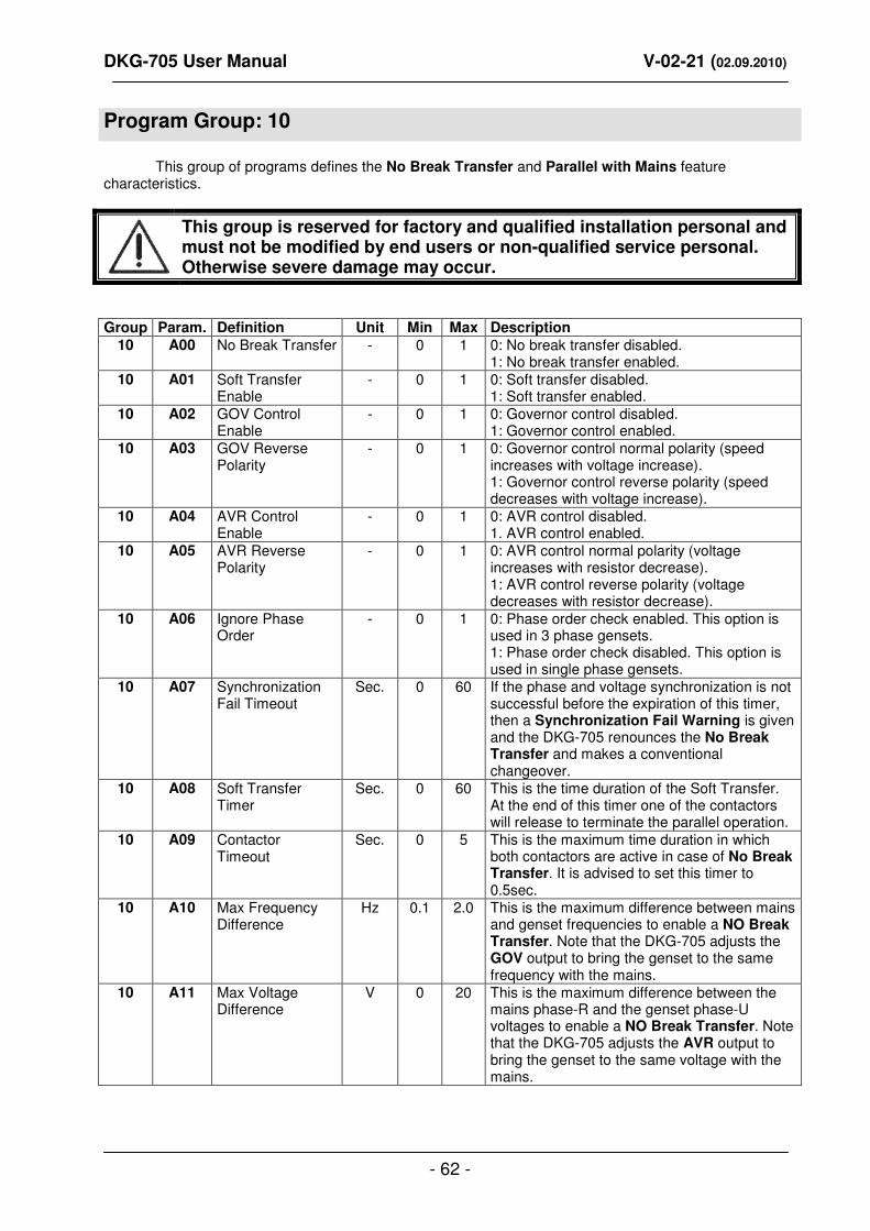
DKG-705 User Manual V-02-21 (02.09.2010)
- 62 -
Program Group: 10
This group of programs defines the No Break Transfer and Parallel with Mains feature characteristics.
This group is reserved for factory and qualified installation personal and must not be modified by end users or non-qualified service personal. Otherwise severe damage may occur.
Group Param. Definition Unit Min Max Description
10 A00 No Break Transfer - 0 1 0: No break transfer disabled. 1: No break transfer enabled.
10 A01 Soft Transfer Enable
- 0 1 0: Soft transfer disabled. 1: Soft transfer enabled.
10 A02 GOV Control Enable
- 0 1 0: Governor control disabled. 1: Governor control enabled.
10 A03 GOV Reverse Polarity
- 0 1 0: Governor control normal polarity (speed increases with voltage increase). 1: Governor control reverse polarity (speed decreases with voltage increase).
10 A04 AVR Control Enable
- 0 1 0: AVR control disabled. 1. AVR control enabled.
10 A05 AVR Reverse Polarity
- 0 1 0: AVR control normal polarity (voltage increases with resistor decrease). 1: AVR control reverse polarity (voltage decreases with resistor decrease).
10 A06 Ignore Phase Order
- 0 1 0: Phase order check enabled. This option is used in 3 phase gensets. 1: Phase order check disabled. This option is used in single phase gensets.
10 A07 Synchronization Fail Timeout
Sec. 0 60 If the phase and voltage synchronization is not successful before the expiration of this timer, then a Synchronization Fail Warning is given and the DKG-705 renounces the No Break Transfer and makes a conventional changeover.
10 A08 Soft Transfer Timer
Sec. 0 60 This is the time duration of the Soft Transfer. At the end of this timer one of the contactors will release to terminate the parallel operation.
10 A09 Contactor Timeout
Sec. 0 5 This is the maximum time duration in which both contactors are active in case of No Break Transfer. It is advised to set this timer to 0.5sec.
10 A10 Max Frequency Difference
Hz 0.1 2.0 This is the maximum difference between mains and genset frequencies to enable a NO Break Transfer. Note that the DKG-705 adjusts the GOV output to bring the genset to the same frequency with the mains.
10 A11 Max Voltage Difference
V 0 20 This is the maximum difference between the mains phase-R and the genset phase-U voltages to enable a NO Break Transfer. Note that the DKG-705 adjusts the AVR output to bring the genset to the same voltage with the mains.
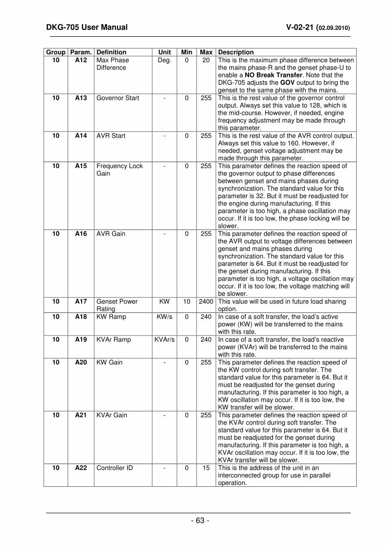
DKG-705 User Manual V-02-21 (02.09.2010)
- 63 -
Group Param. Definition Unit Min Max Description
10 A12 Max Phase Difference
Deg. 0 20 This is the maximum phase difference between the mains phase-R and the genset phase-U to enable a NO Break Transfer. Note that the DKG-705 adjusts the GOV output to bring the genset to the same phase with the mains.
10 A13 Governor Start - 0 255 This is the rest value of the governor control output. Always set this value to 128, which is the mid-course. However, if needed, engine frequency adjustment may be made through this parameter.
10 A14 AVR Start - 0 255 This is the rest value of the AVR control output. Always set this value to 160. However, if needed, genset voltage adjustment may be made through this parameter.
10 A15 Frequency Lock Gain
- 0 255 This parameter defines the reaction speed of the governor output to phase differences between genset and mains phases during synchronization. The standard value for this parameter is 32. But it must be readjusted for the engine during manufacturing. If this parameter is too high, a phase oscillation may occur. If it is too low, the phase locking will be slower.
10 A16 AVR Gain - 0 255 This parameter defines the reaction speed of the AVR output to voltage differences between genset and mains phases during synchronization. The standard value for this parameter is 64. But it must be readjusted for the genset during manufacturing. If this parameter is too high, a voltage oscillation may occur. If it is too low, the voltage matching will be slower.
10 A17 Genset Power Rating
KW 10 2400 This value will be used in future load sharing option.
10 A18 KW Ramp KW/s 0 240 In case of a soft transfer, the load’s active power (KW) will be transferred to the mains with this rate.
10 A19 KVAr Ramp KVAr/s 0 240 In case of a soft transfer, the load’s reactive power (KVAr) will be transferred to the mains with this rate.
10 A20 KW Gain - 0 255 This parameter defines the reaction speed of the KW control during soft transfer. The standard value for this parameter is 64. But it must be readjusted for the genset during manufacturing. If this parameter is too high, a KW oscillation may occur. If it is too low, the KW transfer will be slower.
10 A21 KVAr Gain - 0 255 This parameter defines the reaction speed of the KVAr control during soft transfer. The standard value for this parameter is 64. But it must be readjusted for the genset during manufacturing. If this parameter is too high, a KVAr oscillation may occur. If it is too low, the KVAr transfer will be slower.
10 A22 Controller ID - 0 15 This is the address of the unit in an interconnected group for use in parallel operation.

DKG-705 User Manual V-02-21 (02.09.2010)
- 64 -
Group Param. Definition Unit Min Max Description
10 A23 Parallel Check Timeout
Sec. 0.0 25.0 This is the delay after the mains contactor is energized (for parallel to mains) and before the protections for mains failure are enabled. These protections will deenergize the mains contactor in case of a mains failure in order to prevent the genset from feeding the network.
10 A24 Reverse Power Limit
KW 0 1000 This parameter defines the sensitivity of the reverse power protection while operating in parallel with the mains. When the parallel protections are enabled, if the genset supplies a power over this limit to the mains, the mains contactor will be deenergized and a warning will be generated. It is advised to set this parameter to 15% of the genset power rating.
10 A25 ROCOF df/dt Limit
Hz/Sec 1.0 25.0 This parameter defines the sensitivity of the ROCOF (rate of change of frequency) protection while operating in parallel with mains. When the parallel protections are enabled, if the mains frequency change exceeds this limit for 4 consecutive periods, the mains contactor will be deenergized and a warning will be generated. It is advised to set this parameter to 4 Hz/Sec.
10 A26 Vector Shift Limit Degr. 1 30 This parameter defines the sensitivity of the vector shift protection while operating in parallel with mains. When the parallel protections are enabled, if the phase of the mains measured on last 2 cycles jumps over this limit on the phase measured on last 4
th
and 5th period, the mains contactor will be
deenergized and a warning will be generated. It is advised to set this parameter to 10 degrees.
10 A27 Peak Lopping Enable
- 0 1 0: Peak lopping disabled. In AUTO mode the genset will start only if a mains failure occurs. 1: Peak lopping enabled. In AUTO mode, the genset will start and share the load if the mains power exceeds P_A29 (genset start power).
10 A28 Peak Lopping: Mains Power Limit
KW 0 5000 In peak lopping mode, the unit will not allow the mains to deliver to the load a power higher than this limit in order to protect the mains.
10 A29 Peak Lopping: Genset Start Limit
KW 0 5000 In peak lopping mode the genset will start and enter in parallel with the mains only if the mains power exceeds this limit. However it will supply power to the load only if the load power exceeds P_A28 (mains power limit). This parameter should be set lower than P_A28.
10 A30 Peak Lopping: Genset Stop Limit
KW 0 5000 In peak lopping mode the genset will stop only when the total load power falls below this limit. This parameter should be set lower than P_A29 (genset start limit).
10 A31 Dual Genset Operation Enable
- 0 1 0: Single genset operation. 1: Dual genset operation.

DKG-705 User Manual V-02-21 (02.09.2010)
- 65 -
Group Param. Definition Unit Min Max Description
10 A32 Single Genset Load Enable (dual genset mode)
- 0 1 0: Single genset loading disabled. On mains failure both gensets will run and synchronize between them, after this the load will be transferred to gensets. 1: Single genset loading enabled. On mains failure, at first the master genset will take the load and then the slave genset will synchronize and share the load. Also when one of the gensets fails, the other will be authorized to feed the load.
10 A33 Dual Genset No Break Transfer to Mains Enable
- 0 1 0: No break transfer disabled. 1: No break transfer enabled.
10 A34 Dual Genset Soft Transfer to Mains Enable
- 0 1 0: Soft transfer disabled. 1: Soft transfer enabled.
10 A35 Dual Genset Delayed Start Power
% 0 100 If the total active load is above this level for the period defined in P_A38, the slave genset will start, synchronize and share the load. This parameter is defined as a percentage of the Genset Power Rating defined in parameter P_A17.
10 A36 Dual Genset Quick Start Power
% 0 100 If the total active load is above this level, the slave genset will start, synchronize and share the load without delay. This parameter is defined as a percentage of the Genset Power Rating defined in parameter P_A17.
10 A37 Dual Genset Delayed Stop Power
% 0 100 If the total active load is below this level for the period defined in P_A38, the slave genset will stop. This parameter is defined as a percentage of the Genset Power Rating defined in parameter P_A17.
10 A38 Dual Genset Start/Stop Delay
Sec 0 120 This is the time delay used for starting and stopping of the slave genset. Related starting and stopping power levels are defined in parameters P_A35 and P_A37.
10 A39 Master Genset Frequency Lock Gain in Dual Genset Mode
- 0 255 This parameter defines the reaction speed of the governor output to phase differences between the dual genset system and mains phases during synchronization. The standard value for this parameter is 4. But it must be readjusted for the dual genset system during manufacturing. If this parameter is too high, a phase oscillation may occur. If it is too low, the phase locking will be slower.
10 A40 Master Genset AVR Gain in Dual Genset Mode
- 0 255 This parameter defines the reaction speed of the AVR output to voltage differences between the dual genset system and mains phases during synchronization. The standard value for this parameter is 8. But it must be readjusted for the dual genset system during manufacturing. If this parameter is too high, a voltage oscillation may occur. If it is too low, the voltage matching will be slower.

DKG-705 User Manual V-02-21 (02.09.2010)
- 66 -
Group Param. Definition Unit Min Max Description
10 A41 Power Export to Mains Operation Enable
- 0 1 0: Normal operation. 1: Power Export to Mains operation.
10 A42 Exported active power in Power Export to Mains operation
% 0 100 This is the percentage of the genset power rating (defined in P_A17) to be exported to the mains in Power Export to Mains operation mode.
10 A43 Exported power factor in Power Export to Mains operation
- 60 140 This is the power factor of the power exported to the mains in Power Export to Mains operation mode. The usage is as below: 60..100: inductive 0.60 to 1.00 101..140: capacitive 0.99 to 0.60 Examples: 90 -> 0.90 inductive 110 -> 0.90 capacitive

DKG-705 User Manual V-02-21 (02.09.2010)
- 67 -
Program Group: 11
This group of programs defines the calibration coefficients for the voltage and current measurements.
This group is strictly reserved for manufacturing process and must not be modified. Otherwise faulty measurements and unpredicted operation may occur.
Group Param. Definition Min Max Description
11 B00 Phase R Calibration 0 60000 Each parameter defines the sensitivity of one measurement input. If the parameter increases, the input becomes more sensitive and reads a higher value. The calibration must be verified with a certified calibrated test equipment.
11 B01 Phase S Calibration 11 B02 Phase T Calibration 11 B03 Phase U Calibration 11 B04 Phase V Calibration 11 B05 Phase W Calibration 11 B06 Current R Calibration 11 B07 Current S Calibration 11 B08 Current T Calibration 11 B09 Current U Calibration 11 B10 Current V Calibration 11 B11 Current W Calibration 11 B12 Battery Voltage
Calibration

DKG-705 User Manual V-02-21 (02.09.2010)
- 68 -
24. TROUBLESHOOTING
The genset starts to operate while AC mains are OK or faulty voltage or frequency measurements: Check engine body grounding. AC mains voltages may be outside programmed limits. Mains frequency may be outside limits. Check the AC voltage readings by pressing the MENU button. Check the mains frequency reading by pressing the MENU button. Upper and lower limits of the mains voltages may be too tight. Upper and lower limits of the mains frequency may be too tight. Get in the PROGRAM mode and check for the mains voltage and frequency upper and lower limits. If necessary, widen the limits.
The genset continues to operate after AC mains are reestablished: Check engine body grounding. Widen the AC voltage limits. The hysteresis value for the AC voltages is programmable (P_620). When the AC mains fail, the lower limit is raised and the upper limit is reduced by the hysteresis value to prevent a new load transfer after the load is transferred to the mains.
AC voltages displayed on the unit are not correct: Check engine body grounding. The error margin of the unit is +/- 3 volts. If there are faulty measurements only when the engine is running, there may be a faulty charging alternator or voltage regulator on the engine. Disconnect the charging alternator connection of the engine and check if the error is removed.
KW and cosΦ readings are faulty although the Amp readings are correct: -Current transformers are not connected to the correct inputs or some of the CTs are connected with reverse polarity. Check the connections of each individual CT in order to obtain correct KW and cosΦ for the related phase, then connect all CTs.
Short circuit the outputs of unused Current Transformers.
When the AC mains fails the unit energizes the fuel solenoid, but does not start, then gives fail to start alarm: The unit is not supplied with battery (-) voltage at the oil pressure input. -Oil pressure switch not connected. -Oil pressure switch connection wire cut. -Oil pressure switch faulty. -Oil pressure switch closes too lately. If oil pressure falls, the unit will start. Optionally oil pressure switch may be replaced.

DKG-705 User Manual V-02-21 (02.09.2010)
- 69 -
The engine does not run after the first start attempt, then the unit does not start again: -The oil pressure switch closes very lately. As the unit senses an oil pressure, it does not start. When oil pressure falls the unit will start. Optionally the oil pressure switch may be replaced.
When the AC mains fails, the engine starts to run but the unit gives FAIL TO START alarm and then the engine stops: -The generator phase voltage is not connected to the unit. Measure the AC voltage between terminals (U) and (Generator Neutral) at the rear of the unit while engine is running. The fuse protecting the generator phase may be failed. A misconnection may be occurred. If everything is OK, turn all the fuses off, and then turn all the fuses on, starting from the DC supply fuse. Then test the unit again.
The unit is late to remove engine cranking: -The alternator voltage rises lately. Also the generator remanant voltage is below 20 volts. The unit removes starting with the generator frequency, and needs at least 20 volts to measure the frequency. If this situation is to be avoided, the only solution is to add an auxiliary relay. The coil of the relay will be between BATTERY (-) and charging alternator D+ terminal. The normally closed contact of the relay will be connected serially to the unit's START output. So the starting will also be removed when the D+ pulls to battery positive.
The unit is inoperative: Measure the DC-supply voltage between (+) and (-) terminals at the rear of the unit. If OK, turn all the fuses off, then turn all the fuses on, starting from the DC supply fuse. Then try the unit again.
Programs are modified but not stored: -The modified program value is saved after the next depression on MENU button. Press MENU before exiting the program mode.
Programs can not be modified: The program lock input disables program modifications. Disconnect the program lock input from battery negative before modification. Do not forget to make this connection again to prevent unauthorized program modifications.
The unit makes an Interrupted Transfer although No Break Transfer or Soft Transfer is selected: There may be a phase sequence failure on the mains or generator side. The synchronization process may be failed. Voltage or phase not matched. Check chapter 7 for synchronization conditions.
Parallel with mains : The unit gives PARALLEL MAINS FAIL warning although mains are OK: One of the protection functions is too sensitive. Check protection specific warning on the ALARM LIST menu of the unit and reduce the sensitivity of the corresponding protection using the programming menu.

DKG-705 User Manual V-02-21 (02.09.2010)
- 70 -
Synchronization failure: Check the parameters P_A02, P_A04, P_A15 and P_A16. If Dual Genset mode is used then check also P_A39 and P_A40. If one of them is defined too low, this may delay or disable the synchronization process. Check the synchronization fail timeout parameter (P_A07), if necessary increase. A typical delay may be 20 seconds. Check the synchronization limits (P_A10, P_A11, P_A12), If necessary widen the limits. A typical application may be P_A10=0.5Hz, P_A11=5V, P_A12=5º
25. DECLARATION OF CONFORMITY
The unit conforms to the EU directives
-2006/95/EC (low voltage)
-2004/108/EC (electro-magnetic compatibility)
Norms of reference:
EN 61010 (safety requirements)
EN 61326 (EMC requirements)
The CE mark indicates that this product complies with the European requirements for safety,
health environmental and customer protection.
A certification from European notified body is available on request.
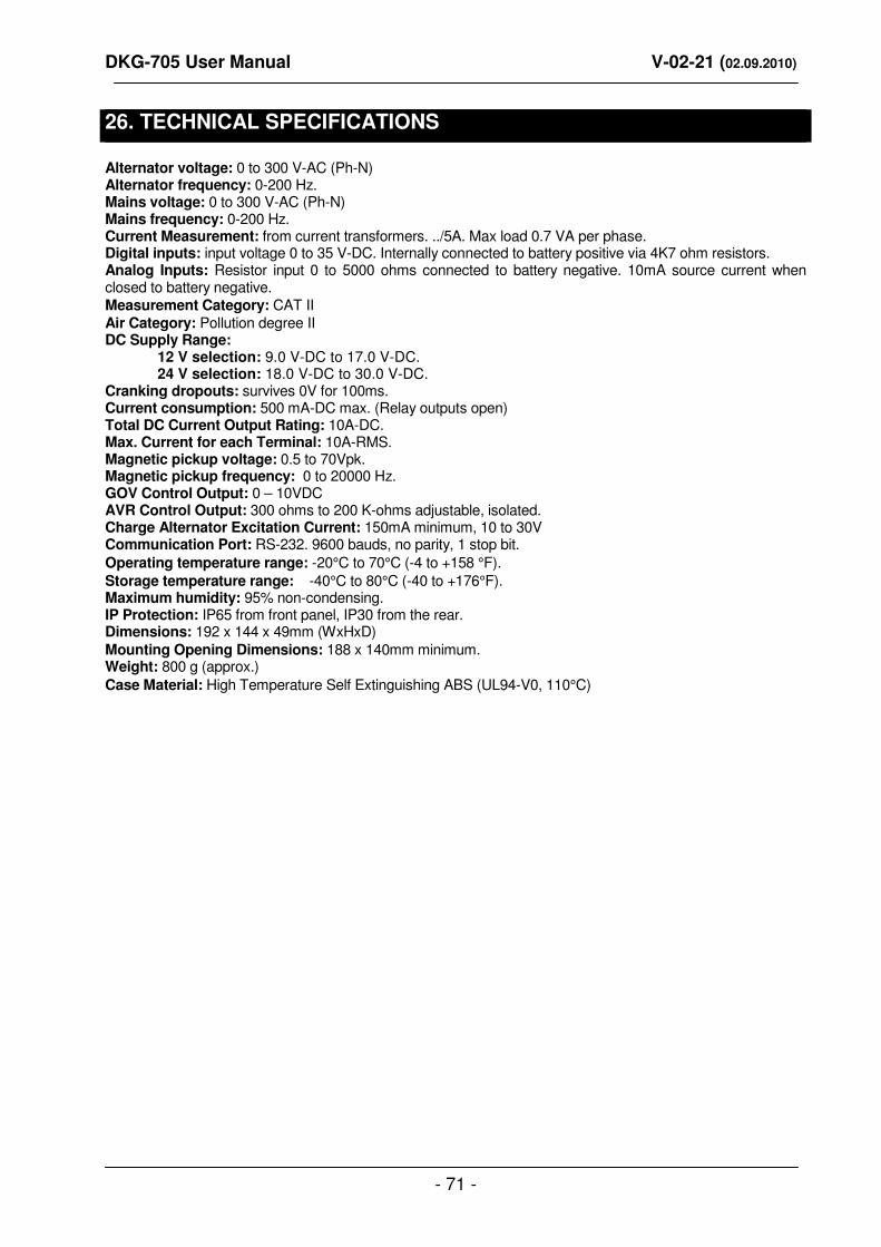
DKG-705 User Manual V-02-21 (02.09.2010)
- 71 -
26. TECHNICAL SPECIFICATIONS
Alternator voltage: 0 to 300 V-AC (Ph-N) Alternator frequency: 0-200 Hz. Mains voltage: 0 to 300 V-AC (Ph-N) Mains frequency: 0-200 Hz. Current Measurement: from current transformers. ../5A. Max load 0.7 VA per phase. Digital inputs: input voltage 0 to 35 V-DC. Internally connected to battery positive via 4K7 ohm resistors. Analog Inputs: Resistor input 0 to 5000 ohms connected to battery negative. 10mA source current when closed to battery negative.
Measurement Category: CAT II Air Category: Pollution degree II DC Supply Range: 12 V selection: 9.0 V-DC to 17.0 V-DC. 24 V selection: 18.0 V-DC to 30.0 V-DC. Cranking dropouts: survives 0V for 100ms. Current consumption: 500 mA-DC max. (Relay outputs open) Total DC Current Output Rating: 10A-DC. Max. Current for each Terminal: 10A-RMS. Magnetic pickup voltage: 0.5 to 70Vpk. Magnetic pickup frequency: 0 to 20000 Hz. GOV Control Output: 0 – 10VDC AVR Control Output: 300 ohms to 200 K-ohms adjustable, isolated. Charge Alternator Excitation Current: 150mA minimum, 10 to 30V Communication Port: RS-232. 9600 bauds, no parity, 1 stop bit.
Operating temperature range: -20°C to 70°C (-4 to +158 °F).
Storage temperature range: -40°C to 80°C (-40 to +176°F). Maximum humidity: 95% non-condensing. IP Protection: IP65 from front panel, IP30 from the rear. Dimensions: 192 x 144 x 49mm (WxHxD)
Mounting Opening Dimensions: 188 x 140mm minimum. Weight: 800 g (approx.)
Case Material: High Temperature Self Extinguishing ABS (UL94-V0, 110°C)

DKG-705 User Manual V-02-21 (02.09.2010)
- 72 -
26. CONNECTION DIAGRAM