Embed Size (px)
Citation preview

DIY J1772 EVSEWritten By: Feitan
DIY J1772 EVSE
© 2017 www.botsbits.org Page 1 of 14

INTRODUCTION
To begin with this is not for the feint of heart as you will be working with 220V at possibly as much as80A. That being said, I TAKE NO RESPONSIBILITY FOR YOU ELECTROCUTING YOURSELF. Ifyou don't have experience with High Voltage/High Current I'd advise you not to even attempt this.(Dire warning, I know. BUT I don't want to hear about anyone earning themselves a Darwin Award forattempting this. There is too many of those these days resulting from copper theft.)
>>>I take no responsibility for you "bricking" your car for your not wiring things properly. <<<
Designing an EVSE, or charger as some say, is a great learning experience as well as having controlof the form factor make it well worth the time and trouble to make one.
>>>READ THE ENTIRE INSTRUCTABLE BEFORE YOU TRY TO BUILD THIS!!!<<<
I also assume that you know how to work safely, and how to wire things in reference to a schematic.
DIY J1772 EVSE
© 2017 www.botsbits.org Page 2 of 14

Step 1 — Tools and Supplies
What you will need: *J1772 EVSEcontrol board - Open EVSE project(should be in Google Code, and theyhave great diagrams for EVSEs.),*J1772 Plug & Cord assembly -TucsonEV, *Contactor/Relay/SSR -Electrical Supply, *Box - HomeDepot, *12v PSU - Electronics Shop,* Strain Relief for J1772 cableassembly - Electrical Supply
CR Magnetics 8420-1000-G -DigiKey, *Heat-shrink tubing -Electronics Shop
Tools: Volt Meter, Drill, Taps,Screws/bolts, Electrical Tape,Knife/stripping tool, DiagonalCutters, Micro Torch/Heat Gun
DIY J1772 EVSE
© 2017 www.botsbits.org Page 3 of 14
Step 2 — A little Background
From Wikipedia: SAE J1772
SAE J1772 is a North Americanstandard for electrical connectors forelectric vehicles maintained by theSociety of Automotive Engineers andhas the formal title "SAE SurfaceVehicle Recommended PracticeJ1772, SAE Electric VehicleConductive Charge Coupler”.
It covers the general physical,electrical, communication protocol,and performance requirements forthe electric vehicle conductivecharge system and coupler.
The intent is to define a commonelectric vehicle conductive chargingsystem architecture includingoperational requirements and thefunctional and dimensionalrequirements for the vehicle inletand mating connector.
DIY J1772 EVSE
© 2017 www.botsbits.org Page 4 of 14

Step 3 — Design
First thing that you want to do whenmaking your EVSE is layout theparts in the case and make sure thatthe case that you have gotten is bigenough. (If you want to mount thisoutside get a NEMA approved watertight case.)
I thought that I'd be different andmount most of my hardware in acase that is designed to be a flush-mount with the wall.
When you have all of the parts,position them in the enclosure sothat you can visualize the locationsof where they are going to bemounted. It is also good to note thatyou may want to make aHV/HP(High Voltage/High Potential)and a LV/LP(Low Voltage/LowPotential) side.
This allows for troubleshooting witha reduced risk of electrocution. Besure to mount the GFCI Doughnut(the CR magnetics currenttransformer) close enough to thecontrol board so you can reach itwith the leads.
When you get everything the wayyou like it, mark the holes. This'llcome in handy later.
DIY J1772 EVSE
© 2017 www.botsbits.org Page 5 of 14

The file below will give you a generalidea as to what we are doing and itshould be referenced as it is thedesign we are going off of. It is alsothe exact wiring diagram for using acontactor. (Thanks go to the OpenEVSE project for the file.)
DIY J1772 EVSE
© 2017 www.botsbits.org Page 6 of 14
Step 4 — Got Control? (Mounting the EVSE controller)
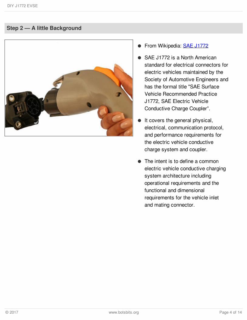
The controller board functions as ourGFCI and as our COMMS board thatcommunicates with the vehicle toclose the contactors or SSRs.
EVSE control boards usually have 2-4 mounting holes. The best way tomount one is to lay the board intothe case and mark the holes with asharpie. Then Drill and tap the holes.(I don't mean tap with your fingereither.) Once you get your controlboard mounted you should beconnecting wires as you go along.
IF an LCD is wanted it can bepurchased and installed in the case.Just be sure to cut a hole big enoughfor you to be able to mount the LCDthat you chose.
This is the time to configure thecontrol board for what amperagesetting that you want. Use a settingthat is under your breaker size by atleast 20%. This is to accommodateNFPA and NEC electricalrequirements. Follow the instructionsthat are on the Open EVSE site forconfiguring your control board usingthe Arduino IDE.
DIY J1772 EVSE
© 2017 www.botsbits.org Page 7 of 14

Step 5 — HV Ahead (mounting the contactor)
A contactor is basically a GIANTrelay capable of switching highamperage at high voltage. Whenmounting the contactor try to mountit close to where you are wantingyour EVSE cable to come out. Themounting depends on how big yourcontactor is.
For this application you should get a12v Automotive relay as some of thecontactors require 120/240v toclose. This automotive relay is usedto bump the voltage up to the correctvoltage for closing the contractorand as such the contractor leadsshould be mounted to the N/O sideof the relay.
A SSR does the same thing as acontactor but it is solid state and ingeneral requires smaller voltage tocomplete the circuit. The SSRs needto be mounted on a heatsink with afan to keep them cool. Againmounting varies with each, but I'llgive a general idea of how to mountthem.
Wether mounting SSRs or acontactor, mark and drill your holes.Tap each hole and thread a screwfrom the BACK of the EVSE'senclosure. This allows you to usejust nuts on the inside of your EVSE.Tighten them down to hold them intothe EVSE.
DIY J1772 EVSE
© 2017 www.botsbits.org Page 8 of 14
Wire the SSRs or contactor up to theEVSE controller board. (I assumeyou know that + is positive, - isnegative, and ~ means AC voltage.)
At this stage it might be a good ideato connect power leads for the PSUof your choice. These leads will bediscussed further in the next step.
Step 6 — The low end (12v PSU)
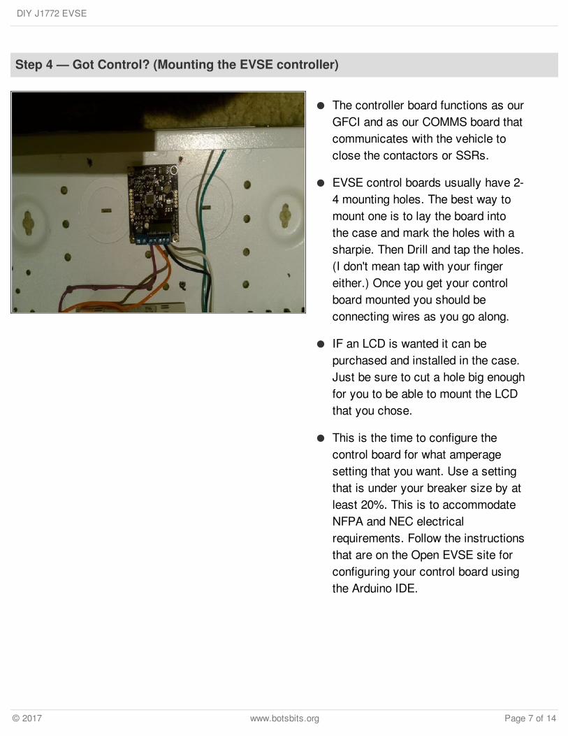
The Power leads you connected tothe Supply side of the SSRs orcontactor in the last step are goingto be put to use now in the poweringof the control board. "But," you say,"the control board uses 12v DC notAC." That is what the power supplyis for. It converts 120/240v AC into12v DC.
Mount the PSU into the enclosure.There are typically 2-4 screws thathold it into place. (NOTE: 3MMoulding Mount Tape can mountyour PSU to the case instead ofusing screws.)
Hook up the leads from the supplyside of the SSRs to the AC side ofthe PSU. The 12v Output from thePSU goes to the EVSE controlboard. (Again, I assume you knowthat + is positive, - is negative, and~ means AC.)
DIY J1772 EVSE
© 2017 www.botsbits.org Page 9 of 14

Step 7 — Cables, Cables, Cables where would we be without you? (mount and attach theJ1772 connector)
Now that you have the contactor mounted and the control board mounted, you need the J1772cable with connector.
Now there are many ways to attach the cable, this I will leave up to you. BUT before you do put theCurrent Transformer onto the 2 120v lines. The cables run through the center of the transformer.Then attach the end to the load side of the SSRs or contactor.
The ground line connects to the chassis ground bolt.
The J1772 pilot line connects to the EVSE control board.
DIY J1772 EVSE
© 2017 www.botsbits.org Page 10 of 14

Step 8 — Breaker One-Nine (Circuit breaker selection and installation)
According to NEC and NFPA, youshould select a breaker with a ratingof at least 20% over what you'll bepulling. So, if you configured theEVSE board for 70A you need atleast a 90A breaker. Follow theinstructions that came with thebreaker for install. (They typicallyrock-in.)
DIY J1772 EVSE
© 2017 www.botsbits.org Page 11 of 14
Step 9 — Ouch, Shocked myself (testing)
As implied by the title, use the volt meter to check the voltage during testing. The 220v side ofthings will show something around 208-240v. Don't be alarmed if you see 240v, most EVs canhandle this voltage without incident.
Have an electrician come out if the voltage is any higher (i.e. 250v), because you may beshortening the life of fuses in your EV. (I have had this happen and it is an expensive repair.) If youhave close to 250v have a licensed electrician do a Power Quality Analysis and look specificallyfor transients as they kill fuses.
Remember this though, "One Flash and you're Ash". That is a principal you should always work by.Check every connection with a volt meter BEFORE you handle anything on the HV/HP side. MakeDOUBLE sure that there is no voltage and that the circuit breaker going to the Mains is turned off.
If a disconnect is required, lock the enclosure with a padlock after you turn it off. (That way somekid doesn't turn the Mains back on while you're working.) Then check the connections.
IF all went well, you should have a working EVSE. If not follow the troubleshooting instructions onthe Open EVSE page.
(Sorry for no photo, having a dispute with some as to the cause of a fuse failure and am notwanting to give them ammo.)
DIY J1772 EVSE
© 2017 www.botsbits.org Page 12 of 14

This document was last generated on 2017-06-23 02:04:10 AM.
Step 10 — Finish IT! (WE ARE DONE!!)
Coat of Paint anyone?? Then maybe some clear coat. Other than that you are done withconstruction. Now you need to mount the thing, which would be another instructable entirely.
DIY J1772 EVSE
© 2017 www.botsbits.org Page 13 of 14