Embed Size (px)
Citation preview

, , DP-1337
fb;(8,3
DISSOLVING URANIUM OXIDEALUMINUM FUEL
W. C. Perkins
C[U PONJ) REG. U. $. PAT. orr
R E· .ft. n n ~O' ~u' ~ q ~'.\ ~ ~~..; ~ ,:to "\
COpy DO NOT RELEASE
FROM FIL..E
Savannah River Laboratory
Aiken, South Carolina
, !
NOTICE
This report was prepared as an account of work sponsored by the United States Government. Neither the United States nor the United States Atomic Energy Commission, nor any of their employees, nor any of their contractors, subcontractors, or their employees, makes any warranty, express or implied, or assumes any legal liability or responsibility for the accuracy, completeness or usefulness of any information, apparatus, product or process disclosed, or represents that its use would not infringe privateJy owned rights.
Printed in the United States of America Available from
National Technical Information Service U. S. Department of Commerce
5285 Port Royal Road Springfield, Virginia 22151
Price: Printed Copy $4.00; Microfiche $1.45

hb~51:S DP-1337
Metals, Ceramics, and Materials (TID-4S00, UC-2S)
DISSOLVING URANIUM OXIDE':'·
ALUMINUM FUEl
by
W. C. Perkins
Approved by
J. A. Porter, Research Manager Separations Chemistry Division
Publication Date: November 1973
E. I. DU PONT DE NEMOURS & COMPANY
SAVANNAH RIVER LA80RATORY
AIKEN. S. C. 29801
CONTRACT AT(07·2).1 WITH THE
UNITED STATES ATOMIC ENERGY COMMISSION

ABSTRACT
The dissolution of aluminum-clad uranium oxide-aluminum fuel was studied to provide basic data for dissolving this type of enriched uranium fuel at the Savannah River Plant. The studies also included the dissolution of a similar material prepared from scrap uranium oxides that were to be recycled through the solvent extraction process. .
The dissolving behavior of uranium oxide-aluminum core material is similar to that of U-AI alloy. Dissolving rates are rapid in HN0 3-Hg(N0 3)2 solutions. Irradiation reduces the dissolving rate and increases mechanical strength.
A dissolution model for use in nuclear safety analyses is developed, based on the observed dissolving characteristics.
- 2 -
CONTENTS
Page
Introduction 5
Experimental 6
Preparation of Test Specimens 6
Dissolution Tests 6
Dissolving Behavior 8
Dissolving Rates. 8
Fragment Formati on 13
A Dissolution Model for Nuclear Safety Analyses 16
Appendix. Preparation, Characterization, and Seleceion 19 of Uranium Oxide for Cermet Fuel Cores
References 23
- 3 -

LIST OF TABLES AND FIGURES
Table
I Composition of Unirradiated Uranium OxideAluminum Tubes . . ..
II Acid Insoluble Residues
III Test Conditions ....
IV Fragments Formed During Dissolution
7
7
7
13
A-I Compositions and Properties of Uranium Oxides ... 21
Figures
1 Dissolving Rate of Unirradiated Uranium Oxide-Aluminum Tubes in Boiling 3M HNO, . . 8
2 Dissolving Rate of Irradiated U30 B-Al Tubes in Boiling 3M HNO,-O.002M Hg2+ . . .
3 Dissolving Rate of Scrap UO -AI Tubes in x Boiling 7M HN03 . . . . . . . .
4 Scrap UOx-Al Test Specimens (I)
5 Scrap UOx-Al Test Specimens (II) .
6 Unirradiated U3OB-Al Test Specimens
7 Irradiated, Declad U,OB-Al Test Specimen
8 Strength of Partially Dissolved Uranium Oxide-Al Tubes
9 Idealized Dissolution Model
A-I U30B Production Procedure for HFIR Fuel ..
A-2 Weight Loss of Uranium Oxides Under Vacuum
- 4 -
9
10
10
11
12
12
15
17
20
22
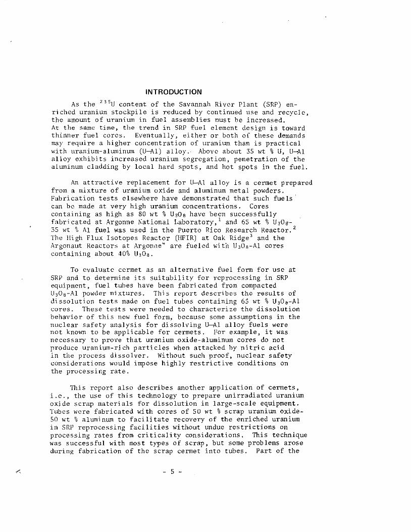
INTRODUCTION
As the 235U content of the Savannah River Plant (SRP) enriched uranium stockpile is reduced by continued use and recycle, the amount of uranium in fuel assemblies must be increased. At the same time, the trend in SRP fuel element design is toward thinner fuel cores. Eventually, either or both of these demands may require a higher concentration of uranium than is practical with uranium-aluminum (U-Al) alloy. Above about 35 wt % U, U-Al alloy exhibits increased uranium segregation, penetration of the aluminum cladding by local hard spots, and hot spots in the fuel.
An attractive replacement for U-Al alloy is a cermet prepared from a mixture of uranium oxide and aluminum metal powders. Fabrication tests elsewhere have demonstrated that such fuels can be made at very high uranium concentrations. Cores containing as high as 80 wt % U308 have been successfully fabricated at Argonne National Laboratory,' and 65 wt % U30.-35 wt % Al fuel was used in the Puerto Rico Research Reactor. 2
The High Flux Isotopes Reactor (HFIR) at Oak Ridge' and the Argonaut Reactors at Argon.1e" are fueled with U,08-Al cores containing about 40% U,08.
To evaluate cermet as an alternative fuel form for use at SRP and to determine its suitability for reprocessing in SRP equipment, fuel tubes have been fabricated from compacted U,08-Al powder mixtures. This report describes the results of dissolution tests made on fuel tubes containing 65 wt % U30.-Al cores. These tests were needed to characterize the dissolution behavior of this new fuel form, because some assumptions in the nuclear safety analysis for dissolving U-Al alloy fuels were not known to be applicable for cermets. For example, it was necessary to prove that uranium oxide-aluminum cores do not produce uranium-rich particles when attacked by nitric acid in the process dissolver. Without such proof, nuclear safety considerations would impose highly restrictive conditions on the processing rate.
This report also describes another application of cermets, i.e., the use of this technology to prepare unirradiated uranium oxide scrap materials for dissolution in large-scale equipment. Tubes were fabricated with cores of 50 wt % scrap uranium oxide-50 wt % aluminum to facilitate recovery of the enriched uranium in SRP reprocessing facilities without undue restrictions on processing rates from criticality considerations. This technique was successful with most types of scrap, but some problems arose during fabrication of the scrap cermet into tubes. Part of the
- 5 -

scrap oxide contained uranates, uranyl fluorides, and nitrates~ and unexpected exothermic reactions generated enough heat to melt a few of the cermet cores. s Dissolution studies of the cermet tubes fabricated from scrap were made to ensure that the tubes could be dissolved safely and efficiently.
This report also includes an Appendix describing the process for producing the U30S powder used in test fuel cores and the basis for the selection of this process from several possible methods.
EXPERIMENTAL
Preparation of Test Specimens
Production quality 65 wt % U30s-35 wt % Al fuel tubes were prepared by heating depleted U03 (0.2 wt % 23SU) at 800°C in a nitrogen atmosphere for 6 hours, blending the resulting U30 S powder with aluminum powder, pressing the blended powders into a cylindrical compact, and extruding the compact, into an aluminum-clad tube. Highly enriched uranium oxide was used in fabricating the tubes for dissolution tests on irradiated fuel. A tube with a 48 wt % U30s-52 wt % Al core was irradiated to 1021 fissions per cubic centimeter of core for these tests.
To demonstrate the feasibility of using powder metallurgy technology to process enriched uranium oxide scrap, 50 wt % scrap uranium oxide-50 wt % aluminum cermet was prepared from impure oxide powders of indefinite composition received from the Rocky Flats Plant (Dow Chemical Co.). Impurities amounted to as much as 52 wt % of these scrap oxides (Table I) and consisted mainly of oxides of iron, chromium, nickel, and silicon (Table II). The scrap cermet was compacted, outgassed, and extruded into tubes clad with aluminum. The experimental studies described here were conducted with oxide containing little or no uranates or other reactive compounds, thereby avoiding the exothermic reactions referred to above.
Dissolution Tests
All of the tubes described in this report were about 4 inches in diameter. The tubes were cut into approximately one-inch
- 6 -

lengths for dissolution tests. The dissolving conditions are given in Table III and are similar to those normally used at SRP for dissolving U-Al alloy fuels. Test specimens were boiled for various timed intervals in a glass dissolver, dried, and tested for mechanical strength and uranium content. Fragments were filtered from the solution for analysis.
TABLE I. COMPOSITION OF UNIRRADIATED URANIUM OXIDE-ALUMINUM TUBES
Al in Core, \~,t 00
Impur j ti cs in Core) wt 9.;
Al in Cladding, \~Tt 0& of tube
/
U30a-Al
59.2
40.8
<0.1
40
Scrap UOx-Al
24
50
26
37
r£l TABLE II. ACI,,-INSOLUBLE RESIDUES
U30 a-Al Scrap Oxide-AI
Wt % of Tube Insoluble (Average value)
Wt % of U insoluhle (Max. observed)
0.2
0.07
2.1
2.2
Residue Com,eosition,
Fe
Al
lJ
IIg
Oxygen
Cr
Si
Others
wt %
8
40
<17
10
8
17
20
21
11
14
12
5
5
12
TABLE Ill. TEST CONDITIONS
Dissolver Solution, £/mol Al
Acid Ratio, mol HN03!mol Al
Initial HN03, M
Hg2 t, t-1
- 7 -
1.4
4.4
3 or 7
0.002 to 0.016

DISSOLVING BEHAVIOR
Dissolving Rates
U,OB-Al tubes dissolved rapidly and completely in boiling 3M HNO,-0.002M Hg(NO,)2. As shown in Figure 1, dissolution of unirradiated tubes was complete in about one hour. Similar tubes irradiated to 10 21 fissions/cm' required about twice as long to dissolve (Figure 2). Cladding on these fuel tubes represents 40% of the total weight (Table I), and 10 to 20 minutes boiling was required to dissolve the 0.020-in.-thick cladding (Figures 1 and 2). Additional time was necessary to dissolve the thicker (0.040 in.) cores. The dissolving rate for unirradiated cores was 0.0004 in./min and, for the 0.040-in. aluminum cladding, 0.002 in/min. These values were reduced by half for cores and aluminum cladding after irradiation.
100r----.-----,~--~----OT----._----r_--_.----_,
" 0.002M Hg ., 80 >
0 ~ ~
0
" ., E 60 u ., c. (/)
., .c => 40
f0-
e Scrap UOx - Al
c: ., ~ ., 20 0-
oL-__ ~ ____ ~ ____ _L ____ ~ ____ ~ ____ L_ __ ~~ __ ~
o 2 3 4
Time, hours
FIGURE 1. DISSOLVING RATE OF UNIRRADIATED URANIUM OXIDEALUMINUM TUBES IN BOILING 3M HNO,
- 8 -

100
90
~ ~
80 > 0 ~
~ 70 0
~ m 60 E u m ~ 50 w ~ ~ ~ 40 ~
0 30 -~
~ e ~ 20 ~
10
0 0
FIGURE 2.
2 3
Time, hour.
DISSOLVING RATE OF IRRADIATED 030B-Al TUBES IN BOILING 3M HN0 3-O.002M Hg(N0 3)2
Scrap oxide-aluminum tubes did not dissolve completely in 3M HN03-0.002M Hg 2+ and reqUired a higher concentration of mercury catalyst (O.008M) for rapid dissolution (Figure 1). In O.002M Hg(N0 3 )2, the scrap oxide tubes dissolved slowly even when the nitric acid concentration was increased to 7M. The addition of KF to O.04M did not increase the dissolving rate substantially (Figure 3). Substantial amounts of mercury were found in the undissolved residue from the scrap oxide tubes (Table II), leading to the conclusion that impurities in the scrap oxide scavenged mercury catalyst from solution, leaving too low a concentration of mercuric ion to overcome the surface passivation of the aluminum cladding. As a result, the core dissolved leaving partially dissolved rings of cladding (Figures 4 and 5). Mercury scavenging was shown experimentally as these rings dissolved rapidly when transferred to fresh 7M HN0 3 solution containing O.002M Hg2+ or when the mercuric ion concentration was increased to O.016M (Figure 3). For comparison, Figures 6 and 7 show partly dissolved core sections of unirradiated and irradiated U30 B-Al that dissolved normally in 3M HN0 3-O.002M Hg(N0 3)2 solution.
- 9 -

100
" I Fre.h 90 ~1 •• Olv.n'
" No KF .. I > "0 80 .. I .!!! O.o02M Hg 0 70 0.04M KF c Q)
E 60 '0 .. "-en 50 .. .c ~ 40 -0
1: 30 .. u ~
8? 20
10
0 0 2 3 4
Time, hours
FIGURE 3. DISSOLVING RATE OF SCRAP UOx-Al TUBES IN BOILING 7M HN0 3
FIGURE 4. SCRAP UOx-Al TEST SPECIMENS (I)
Left: Right:
Undissolved specimen 92% dissolved specimen. Note broken inner cladding, intact outer cladding, and absence of core material.
- 10 -

FIGURE 5. SCRAP UOx-Al TEST SPECIMENS (II)
Left: Undissolved specimen Right: 61% dissolved specimen. Note absence of inner
cladding, partly-dissolved core, and intact outer cladding.
Top: 85% dissolved specimen. Only the outer cladding remains with dark spots of core material.
- 11 -

FIGURE 6. UN IRRADIATED U30s-Al TEST SPECIMENS
left: Undissolved specimen Right: 75% dissolved specimen. ,
Note holes in core and absence of cladding.
FIGURE 7. IRRADIATED. DECLAD U30a-Al TEST SPECIMEN
After dissolution of cladding. small pieces of cladding remain.
- 12 -
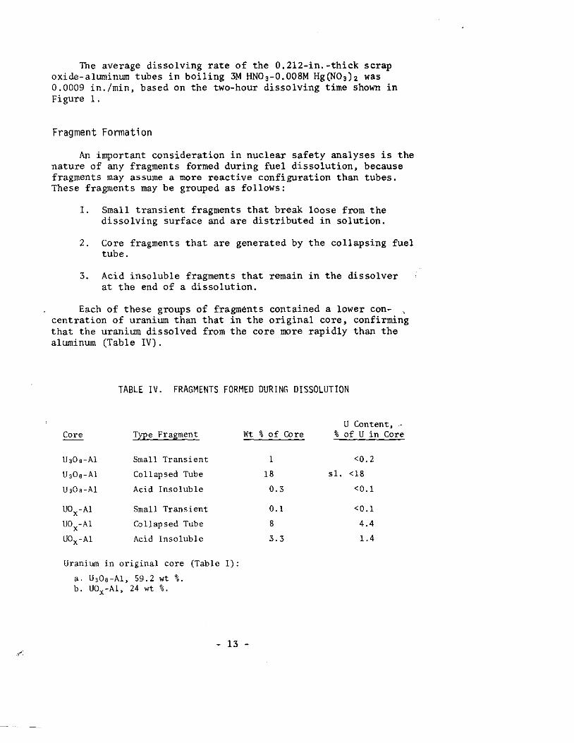
The average dissolving rate of the 0.2l2-in.-thick scrap oxide-aluminum tubes in boiling 3M HNO,-0.008M Hg(NO,h was 0.0009 in./min, based on the two-hour dissolving time shown in Figure 1.
Fragment Formation
An important consideration in nuclear safety analyses is the nature of any fragments formed during fuel dissolution, because fragments may assume a more reactive configuration than tubes. These fragments may be grouped as follows:
I. Small transient fragments that break loose from the dissolving surface and are distributed in solution.
2. Core fragments that are generated by the collapsing fuel tube.
3. Acid insoluble fragments that remain in the dissolver at the end of a dissolution.
Each of these groups of fragments contained a lower con- , centration of uranium than that in the original core, confirming that the uranium dissolved from the core more rapidly than the aluminum (Table IV).
TABLE IV. FRAGMENTS FORt1ED DURING DISSOLUTION
Core
U,O.-Al
U ,O.-Al
U,O.-Al
UOx-Al
UOx-Al
UOx-Al
Type Fragment Wt
Small Transient
Collapsed Tube
Acid Insoluble
Small Transient
Co llap sed Tube
Acid Insoluble
Uranium in original core (Table I):
a. U,O.-Al, 59.2 wt %. b. UOx-Al, 24 wt %.
- 13 -
U Content, _. % of Core % of U in Core
1 <0.2
18 s1. <18
0.3 <0.1
0.1 <0.1
8 4.4
3.3 1.4

The U30B-Al cermet dissolved almost completely; less than 0.1% of the uranium in the tube was found in the small acid insoluble residue. The quantity of acid-insoluble solids (Table IV) was larger for the scrap oxide-aluminum tubes (3.3 wt %) than for the U30 B-Al tubes (0.3 wt %), as expected from the difference in purities of the oxides from which the cores were made. The composition of these residues is shown in Table II. The composition of the solids derived from the fuel was independent of nitric acid concentration, length of dissolving time, and mercury catalyst concentration. Addition of 0.04M KF to the dissolver solution had little, if any, effect on the quantity or composition of the solids. The solids from the scrap oxide-aluminum tubes were finely divided and formed a suspension that settled from the dissolver solution very slowly; even after 24 hours the supernate was not clear. A gelatin treatment clarified the solutions adequately for solvent extraction.
A significant quantity of uranium-containing fragments is produced when the dissolving fuel tube collapses. The quantity of core material that is converted into fragments can be calculated if the wall thickness at the collapse point is known. Since enriched uranium fuel tubes are dissolved at SRP in a vertical position,· partially dissolved cermet sp6cimens were crushed by applying weight along the longitudinal axis of the tubes with either lead weights or a compression-testing machine. The results are shown in Figure 8, a graph of the tube wall thickness vs. the weight necessary to crush the specimen. Since the vertical fuel tubes in the SRP dissolvers are initially partially immersed in the dissolver solution,· weight is impressed on the dissolving portion of the fuel tube by the unimmersed portion. A conservative estimate of the collapse point may be obtained by assuming the initial weight of the tube is impressed on the dissolving portio~. For instance, 40-lb UO -AI tubes would collapse under their full weight when the tuBe thickness decreased to ~0.011 in. (Figure 8). Since these cores are about 0.132 in. thick initially, 11/132 or about 8% of the core material would be converted to fragments.
Unirradiated U30B-AI is about as strong as U-Al alloy (Figure 8). A 20-lb tube of either fuel form will collapse when the wall thickness is reduced to about 0.007 in. Irradiated cermet is stronger; collapse will not occur until the wall thickness is reduced to about 0.004 in . Consequently, collapse of an irradiated cermet tube will generate a smaller mass'of fragments than the collapse of an U-AI alloy tube of similar weight and diameter.
- 14 -

0.030
.s on .. .. 0.020 c:
.>< u
.c. l-
e 0.010 ~ ..
.<> ~
0 0
\) -25'1'0 U-AI Alloy
• .& o
Scrap UOx - A I Unirradiated U!Oe-AI
Irradialed USOe-AI
10 20 30 40
Crush Weight. Ib
50
FIGURE 8. STRENGTH OF PARTIALLY DISSOLVED URANIUM OXIDE - Al TUBES
(Vertical Mode)
60 70
The dissolving behavior of uranium oxide-aluminum fuel ~an be summarized as follows:
1. Dissolving rates are rapid in 3M HN0 3 -O.002M Hg(N0 3)2'
With unirradiated tubes, the aluminum cladding is removed at a rate of ~O.002 in./min; unirradiated cores are attacked at a rate of ~O.0004 in./min.
2. Irradiation will reduce the dissolving rates of both cladding and core by a factor of 2.
3. Impurities in the uranium oxide can result in increased mercury catalyst requirements and increased concentration of uranium in fragments generated.
4. The uranium oxide dissolves faster than the aluminum in the core.
5. The mechanical strength of partially dissolved cermet cores is equal to that of U-Al alloy cores.
6. Irradiated cermet cores are slightly stronger than unirradiated cermet cores.
7. Fragments from the surface of a dissolving core contain 1i ttle uranium.
- 15 -

A DISSOLUTION MODEL FOR NUCLEAR SAFETY ANALYSES
The nuclear safety analyses for dissolving at SRP are based on the "worst case" approach. tions are made to ensure that no combination of ever unlikely, can lead to criticality.
enriched uranium Detailed calculuconditions, how-
The schematic diagram in Figure 9 represents four stages in the model used for nuclear safety analysis of the dissolution of SRP fuel elements: freshly charged whole elements about 1/3 immersed in dissolvent and standing on the fragment "heel" from the previous dissolution (stage 1), partly dissolved elements standing on fragments from the heel plus fragments from collapsed fuel (stages 2 and 3), and undissolved fragments (stage 4). Maximum permissible fragment heights (heel) prior to reloading and dissolver loading limits are determined on the basis of the most reactive of these cases (usually the second stage shown in Figure 9). A conservative feature of this model is the assumption that dissolution proceeds in steps, rather than gradually, i.e., an immersed tube section dissolves uniformly until the tube wall thickness is reduced to the collapse point and then all of the immersed fuel is crushed into fragments by the weight of unimmersed sections of that tube. As a further conservative feature, it is assumed that the terrr.inal uranium concentration exists in the dissolver solution, whether any fuel has dissolved or not.
To provide precise, but conservative, information for use in nuclear safety calculations for cermet fuels with this model, the following statements have been formulated from the dissolution data:
1. Submerged fuel sections retain their shape until dissolved to the thickness (shown in Figure 8) at which the fuel is crushed by the entire weight of an undissolved fuel tube. (Note that no credit is taken for loss in weight during dissolution.)
2. When a tube section collapses, the quantity of core material represented by the maximum immersion depth and by the wall thickness (from Figure 8) is converted to fragments that fall to the bottom of the fuel basket and remain there, under another section of fuel tube, until dissolved.
- 16 -

3. The concentration of uranium in any fragment is the same as the concentration of uranium in the original core material. No credit is taken for selective dissolution of uranium from the core material.
4. The small transient fragments and the acid insoluble fragments (Table IV) generated during dissolution escape the fuel basket and are distributed homogeneously in the dissolver solution. (Note that only the acid insoluble fragments from scrap oxide-aluminum fuel in Table IV require attention, because the uranium contents of the other fragments are so low.)
STAGE I STAGE 2 STAGE 3 STAGE 4 Charged Fuel One-third Dissolved Two-thirds Dissolved Heel
( r=r=
Fuel Basket perforaled
il \
rr
Liquid 7
( b FfQ97_ .. . M • ls!~~~ l.i<> <-
U-O U ,. 1.5 401/1 U .. 3.0 gIl U " 4.5 gil
FIGURE 9. IDEALIZED DISSOLUTION MODEL
- 17 -
APPENDIX
PREPARATION, CHARACTERIZATION, AND SELECTION OF URANIUM OXIDE FOR CERMET FUEL CORES
The U,O, produced at Oak Ridge CY-12 Plant) for use in the HFIR reactor is an ideal oxide for reactor fuel. This oxide is chemically and thermally stable and has both high density and low surface area. However, it is relatively expensive to prepare, and the production capacity at Y-12 is relatively small compared to SRP reactor requirements. The production procedure is shown in Figure A-I. HFIR fuel is fabricated by blending U,O, powder with aluminum metal powder, pressing the mixed powders into a cermet, and cladding the compacted cermet with aluminum.
Samples of oxides obtained from Y-12 were studied in an attempt to define an oxide (with physical characteristics similar to HFIR U,O,) that could be produced more economically in largar quantities. Four oxides were compared. Sample 1 was unsintered uranium trioxide as produced from uranyl nitrate solution in the Y-12 process denitrator. Sample 2 was Y-12 denitrator UO, sintered at soooe in a nitrogen atmosphere. Sample 3 was Y-12 denitrator UO, sintered at soooe in a nitrogen atmosphere and then sintered again at l400 0 e in air. HFIR U30 8 (Sample 4) was used as a standard for comparison of test results; it was produced by heating at soooe in a nitrogen atmosphere and then at l400 0 e in air, as shown in Figure A-I.
The similarity of the physical characteristics of Samples 2 and 3 to HFIR U,08, shown in Table A-I and Figure A-2, indicated that these oxides were promising candidates for reactor fuel. Unsintered U03 (Sample 1) lacked the chemical and thermal stability required. Subsequently, the procedure used in preparing Sample 2 was used to produce the U,08-Al fuel tubes used in the dissolution tests.
The effects of sintering on the composition and properties of Y-12 process UO, are illustrated by the results given in Table A-I. After sintering at soo·e in a nitrogen atmosphere (Sample 2), the oxygen, water, and carbon contents are significantly reduced in comparison with Sample 1 (UO,), and conversion to U,08 is essentially complete. Increasing the sintering temperature to l400 0 e (Sample 3) results in a 3-fold further decrease in water content, an S-fold decrease in surface area, and a significant increase in density. The higher temperature apparently anneals the cracks and pores that form at lower temperatures during denitration and conversion from UO, to U,08.
- 19 -

EFFLUENT __ RECOVERY
UNDERSIZE
PACKAGING
FIGURE A-l. U30B PRODUCTION PROCEDURE FOR HFIR FUEL (Reference 3)
- 20 -
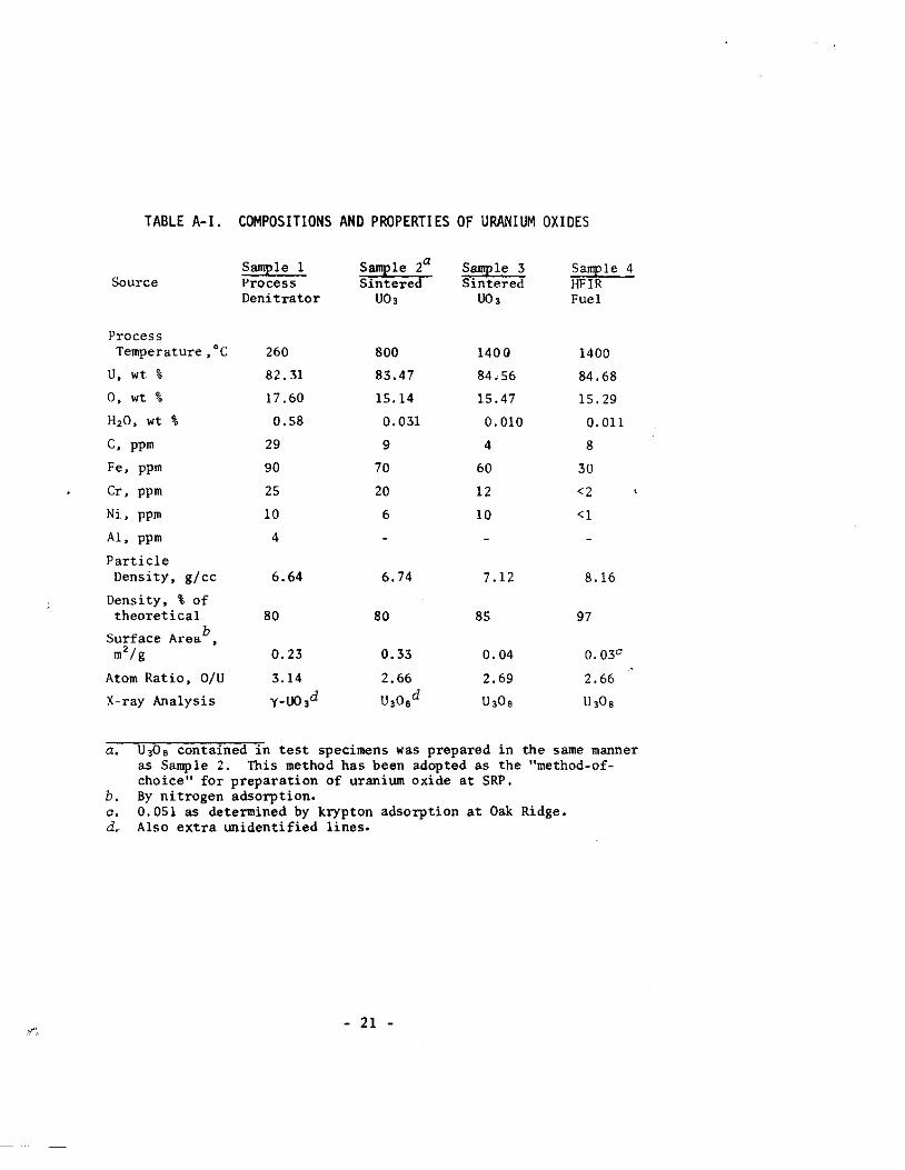
TABLE A-I. COMPOSITIONS AND PROPERTIES OF URANIUM OXIDES
Source
Process Temperature Joe
VJ wt %
C, ppm
Fe, ppm
Cr, ppm
Ni, ppm
A1, ppm
Particle Density, g/cc
Density, % of theoretical
Surface Areab , m'lg
Atom Ratio, O/U
X-ray Analysis
Sample 1 Process Denitrator
260
82.31
17.60
0.58
29
90
25
10
4
6.64
80
0.23
3.14
y_Uo,d
Sample 2a
Sintered UO,
800
83.47
15.14
0.031
9
70
20
6
6.74
80
0.33
2.66
U,O,d
Sample 3 Sintered
UO,
140Q
84.56
15.47
0.010
4
60
12
10
7.12
85
0.04
2.69
U,O,
Sample 4 HFIR Fuel
1400
84.68
15.29
0.01l
8
30
<2
<1
8.16
97
0.03"
2.66
U,O,
a. U30 8 contained in test specimens was prepared in the same manner as Samp 1e 2. This method has been adopted as the "method-ofchoice" for preparation of uranium oxide at SRP.
b. a. d.
By nitrogen adsorption. 0.051 as determined by krypton adsorption at Oak Ridge. Also extra unidentified lines.
- 21 -

500
E "-"-
Sample I .,;
"' 0 -" 1000 Sample 2 _____
:E 0> Sample 3
~
1500 Sample 4
200 400 600 800 1000 1200 Temperature, °c
FIGURE A-2. WEIGHT LOSS OF URANIUM OXIDES UNDER VACUUM
The composltlon and properties of Sample 3 are similar to those of HFIR fuel (Sample 4). Although some of the impurity levels are higher, the differences should not affect reactor operation. Surface area measurements on HFIR fuel at Y-12 gave 0.051 m"/g, somewhat higher than the result in Table A-I. This higher value is probably a result of a more ac·curate measurement, as ORNL uses the BET-Kr method.
The similarity of sintered U0 3 to HFIR fuel is further illustrated by the results of thermogravimetric analysis (TGA) given in Figure A-2. Samples 2, 3, and 4 were stable to weight loss at temperatures below 600°C, which is above the maximum temperature expected during fabrication and irradiation of cermet fuel elements. Considerably larger amounts of gas were released by U03 (Sample 1). Mass spectrometric analysis of the gases evolved showed that in each sample the release of water was essentially complete at 400°C and that carbon dioxide was released in the range 350 to 600°C. Above 600°C, each sample evolved oxygen as U308 was reduced to UO", and Sample 1 also evolved traces of carbon monoxide. Oxygen evolution from Sample 1 began at about 350°C, indicating the onset of conversion of U03 to U308.
- 22 -

REFERENCES
1. H. Bergua, R. Friddle, J. Diaz, and J. Baird. "Fabrication of the ISNSE Fuel Element for Low Power Research Reactors." Nuclear Fuel Elements, H. H. Hausner and J. F. Schumar, eds. Reinhold, New York, p 184 (1959).
2. W. J. Kucera, C. F. Leitten, and R. J. Beaver. Specifications and Procedupes Used in Manufactuping U,Oe-Aluminum Dispersion Fuel Elements fop Cope I of the Puepto Rico Research Reactor. USAEC Report ORNL-3458, Oak Ridge National Laboratory, Oak Ridge, Tenn. (October 1963).
3. W. J. Werner and J. R. Barkman. Charactepization and Production of U,Oefor HFIR. USAEC Report ORNL-4052, Oak Ridge National Laboratory, Oak Ridge, Tenn. (April 1967).
4. R. A. Noland, D. E. Walker, and L. C. Hymes. "Fabrication of U,Oe-Aluminum Dispersion Fuel Elements by Extrusion." MatePials in Nuclear Applications, ASTM, Philadelphia, p 336 (1960).
5. L. W. Gray. "Unexpected Meltdown of Scrap Uranium-Aluminum Cermet Cores During Outgassing." To be published in Nuclear Safety.
6. R. 1. Martens, W. L. Poe, Jr., and A. E. Wible. "Preparation of Aluminum-Clad Uranium Fuels for Solvent Extraction." Chemical EngineePing Ppogpess Symposium Series, Vol. 60, No. 51, P 44 (1964).
- 23 -


![EXAFS Spectroscopic Studies of Uranium (vr) Oxide Precipitates/67531/metadc... · ERNEST ORLANDO LAWRENCE B ERKELEY N ATI o NAL LABO RATC] RY EXAFS Spectroscopic Studies of Uranium](https://img.dokumen.tips/doc/110x75/5e7857afbb0b8521125e8b15/exafs-spectroscopic-studies-of-uranium-vr-oxide-precipitates-67531metadc.jpg)