Embed Size (px)
Citation preview

Display Expansion Board - User’s Guide Copyright 2012 © Embedded Artists AB
EA-USG-1209 Rev A
Display Expansion Board
Get Up-and-Running Quickly and Start Developing Your Application On Day 1!

Display Expansion Board - User’s Guide Page 2
Copyright 2012 © Embedded Artists AB
Embedded Artists AB Davidshallsgatan 16 211 45 Malmö Sweden
[email protected] http://www.EmbeddedArtists.com
Copyright 2012 © Embedded Artists AB. All rights reserved.
No part of this publication may be reproduced, transmitted, transcribed, stored in a retrieval system, or translated into any language or computer language, in any form or by any means, electronic, mechanical, magnetic, optical, chemical, manual or otherwise, without the prior written permission of Embedded Artists AB.
Disclaimer
Embedded Artists AB makes no representation or warranties with respect to the contents hereof and specifically disclaim any implied warranties or merchantability or fitness for any particular purpose. Information in this publication is subject to change without notice and does not represent a commitment on the part of Embedded Artists AB.
Feedback
We appreciate any feedback you may have for improvements on this document. Please send your comments to [email protected].
Trademarks
All brand and product names mentioned herein are trademarks, services marks, registered trademarks, or registered service marks of their respective owners and should be treated as such.

Display Expansion Board - User’s Guide Page 3
Copyright 2012 © Embedded Artists AB
Table of Contents 1 Document Revision History 4
2 Introduction 5
2.1 Features 5
2.2 ESD Precaution 5
2.3 General Handling Care and Usage 6
2.4 CE Assessment 6
2.5 Other Products from Embedded Artists 6
2.5.1 Design and Production Services 6
2.5.2 OEM / Education / QuickStart Boards and Developer’s Kits 6
3 Getting Started 7
3.1 Selecting Video Resolution 7
3.2 Mounting 7
3.3 Power Consumption 8
4 Display Expansion Board Design 9
4.1 Block Diagram 9
4.2 Schematic Walkthrough 9
4.2.1 Page 2 9
4.2.2 Page 3 10
4.2.3 Page 4 10
4.2.4 Page 5 10
4.2.5 Page 6 10
4.2.6 Page 7 10
4.3 Interface Connector Pinning 10
4.4 Pixel Clocks 13
4.5 Things to Note 13
4.5.1 VGA output does not work without fixed frequency oscillator 13
4.5.2 36MHz Pixel Clock Limitations 13
4.5.3 Limited Driver Functionality for TDA19988 14
4.5.4 Picture on Monitors and TV:s 14
4.5.5 Usage - Evaluation 14
4.6 Software Driver 14
4.6.1 Settings for VGA (640x400 px, 60Hz) 15
4.6.2 Settings for SVGA (800x600 px, 56Hz) 15
4.6.3 Settings for 480p (720x480 px, 60Hz) 16
4.6.4 Settings for SVGA (720x576 px, 50Hz) 16
5 Further Information 17
Display Expansion Board - User’s Guide Page 4
Copyright 2012 © Embedded Artists AB
1 Document Revision History
Revision Date Description
PA1 2012-12-12 First released version.
PA2 2012-12-18 Added information about 36MHz limitation.

Display Expansion Board - User’s Guide Page 5
Copyright 2012 © Embedded Artists AB
2 Introduction Thank you for buying the Display Expansion Board from Embedded Artists. The board makes it possible for you to get started with graphical user interface development immediately. The board directly interfaces the OEM Base Board (also from Embedded Artists) and can be mounted with it, forming a compact unit.
2.1 Features
The features of the Display Expansion Board are:
Parallel RGB interface, 16-bit color depth (or 12-bit).
Up to 24-bit color depth supported with manual wiring.
When used together with Embedded Artists Developer’s Kits up to 16-bit color depth is supported.
HDMI/DVI (digital) transmitter via TDA19988 from NXP
Note: limited driver functionality for this chip. CEC/HDCP functionality not implemented.
HDMI/DVI (digital) transmitter via TFP410 from TI
VGA (analog) transmitter via ADV7125KST50 from Analog Devices
LVDS (digital) transmitter via DS90C383BMT from National Semiconductor/TI
Switching between 25.175MHz, 27MHz and 36MHz pixel clocks
Spread spectrum (+-2%) oscillators used for reduced EMI. Works for digital transmitters (HDMI/DVI/LVDS) but not for (analog) VGA.
Provision for programmable spread spectrum oscillator DS1086LU+ from Maxim (not mounted).
Resistive touch screen controller, TSC2046 from TI (normally not used)
I2C-E2PROM with configuration parameters
Controller can read which display board that is connected and initialize the MCU LCD controller and control the Display Expansion board accordingly.
Power control signals via I2C-GPIO
50-pos (2x25) IDC interface connector, compatible with Embedded Artists OEM base board that is used on LPC1788/LPC3250 v2/LPC4088/LPC4357 Developer’s Kits
Proper ESD protection on HDMI, DVI and VGA ports
Powered via interface connector
3.3V and 5V required
Compact size: 165 x 150 mm
Simple mounting together with OEM Base Board
2.2 ESD Precaution
Please note that the Display Expansion Board comes without any case/box and all components are exposed for finger touches – and therefore extra attention must be paid to ESD (electrostatic discharge) precaution.

Display Expansion Board - User’s Guide Page 6
Copyright 2012 © Embedded Artists AB
Make it a habit always to first touch the metal surface of one of the USB connectors on the OEM Base Board (which the Display Expansion Board is connected to) for a few seconds with both hands before touching any other parts of the boards. That way, you will have the same potential as the board and therefore minimize the risk for ESD.
Note that Embedded Artists does not replace boards that have been damaged by ESD.
2.3 General Handling Care and Usage
Handle the Display Expansion Board with care. The board is not mounted in a protective case/box and is not designed for rough physical handling. Connectors can ware out after excessive use. The board is designed for evaluation and prototyping use, and not for integration into consumer or industrial end-products.
2.4 CE Assessment
Note that the Display Expansion Board is classified as a component and is hence not CE marked separately. It can perform different functions in different integrations and it does not have a direct function. It cannot work independently. It is therefore not in the scope of the CE Directive.
The board is an evaluation board (not for integration into an end product) but it has been designed to meet class A level when connected together with the OEM Base Board. In a domestic environment this product may cause radio interference in which case the user may be required to take adequate measures.
2.5 Other Products from Embedded Artists
Embedded Artists have a broad range of LPC1000/2000/3000/4000 based boards that are very low cost and developed for prototyping / development as well as for OEM applications. Modifications for OEM applications can be done easily, even for modest production volumes. Contact Embedded Artists for further information about design and production services.
2.5.1 Design and Production Services
Embedded Artists provide design services for custom designs, either completely new or modification to existing boards. Specific peripherals and I/O can be added easily to different designs, for example, communication interfaces, specific analog or digital I/O, and power supplies. Embedded Artists has a broad, and long, experience in designing industrial electronics in general and with NXP’s LPC1000/2000/3000/4000 microcontroller families in specific. Our competence also includes wireless and wired communication for embedded systems. For example IEEE802.11b/g (WLAN), Bluetooth™, ZigBee™, ISM RF, Ethernet, CAN, RS485, and Fieldbuses.
2.5.2 OEM / Education / QuickStart Boards and Developer’s Kits
Visit Embedded Artists’ home page, www.EmbeddedArtists.com, for information about other OEM / Education / QuickStart boards / Developer’s kits or contact your local distributor.

Display Expansion Board - User’s Guide Page 7
Copyright 2012 © Embedded Artists AB
3 Getting Started This chapter describes important aspects of using the Display Expansion Board.
3.1 Selecting Video Resolution
It is recommended to prototype with a display/monitor/tv that has identical resolution as the intended end-application. If the exact same resolution cannot be used during prototyping, select a resolution as close to the end-application as possible. The reason for this is that different display resolutions give different application program load (program execution time) and different load on the external memory bus, where the frame buffer typically resides. When developing real-time systems, which many embedded system are, it is advised to not alter fundamental things, like system load.
Note that size of the display/monitor/tv is of no importance for the discussion above. It is the resolution that gives a certain load on the application and external memory bus. Size can of course also be important when evaluating the usability and interaction with the user.
The Display Expansion Board supports at least four different standard resolutions and can easily be extended to support more:
VGA, 640x480 pixels, 25.175MHz pixel clock. 60Hz frame frequency.
SVGA, 800x600 pixels, 36MHz pixel clock. 56Hz frame frequency.
480p, 720x480 pixels, 27.027MHz pixel clock. 60Hz frame frequency.
27.000MHz pixel clock is used instead of 27.027MHz.
576p, 720x576 pixels, 27MHz pixel clock. 50 Hz frame frequency.
The Display Expansion Board, support primarily 16- and 12-bit color depth because when increasing the color depth above 16-bits, the memory requirements and external bus load will double. This is at least true for NXP’s LPC-family of processors with integrated LCD controller. Instead of having 2 bytes per pixel (for 16- and 12-bit color depth) 4 bytes are needed per pixel.
3.2 Mounting
The Display Expansion Board can optionally be mounted with the OEM Base Board. The board is mounted the same way as other LCD boards. The product and support page both contains a link to a short video demonstrating how to mount the LCD Board together with the OEM Base Board. Before mounting, watch the instruction video. The Display Expansion Board is mounted the same way as the LCD Board. A Phillips screw driver #1 and a small adjustable spanner are needed to complete the mounting.
Note that it is not strictly needed to mount the Display Expansion Board together with the OEM Base Board. It is just practical. It is also possible to have the board beside the OEM Base Board. Figure 1 below illustrates how it looks like when the two boards are mounted together.

Display Expansion Board - User’s Guide Page 8
Copyright 2012 © Embedded Artists AB
Figure 1 – Display Expansion Board and OEM Base Board Mounting
3.3 Power Consumption
The board needs both a +3.3V and +5V supply. +5V is needed for the all the interfaces.
If the OEM Base Board is used to power the Display Expansion Board and the OEM Base Board is powered via a USB Host port, the current consumption is close to what many USB Host ports can supply. In many cases it will work just fine, but sometimes an external +5V/1A supply is needed.
Note that if an external LCD panel is supplied via the LVDS interface the power consumption can be considerably higher than 1A. A +5V/2-3A supply might be needed in that case.

Display Expansion Board - User’s Guide Page 9
Copyright 2012 © Embedded Artists AB
4 Display Expansion Board Design This chapter describes the hardware design of the Display Expansion Board. The schematic can be downloaded from the support page after registering the product serial key (that comes with purchase of the Display Expansion Board). It can be good to have the schematic side by side when reading this chapter.
4.1 Block Diagram
The block diagram in Figure 2 below gives a quick overview of a design. It illustrates the major components in the design.
Figure 2 – The Display Expansion Board Block Diagram
4.2 Schematic Walkthrough
4.2.1 Page 2
J1 is the interface connector to the board. It carries the parallel RGB pixel data as well as control signals. SPI and I2C serial channels are also present.
The data signals are connected to that TFT5:6:5 and TFT4:4:4 modes of the LPC on-chip LCD controllers are supported. 24-bit color (TFT8:8:8) depth is supported with some manual wiring, see section 4.3 below for details.
All high-speed signals have 100 ohm series resistors in order to minimize signal reflections on the board.
There are three spread spectrum oscillators, 25.175MHz/27MHz/36MHz, which can generate a pixel clock to the LPC LCD controller. The frequencies have been selected to comply with standard display settings (VGA/SVGA/480p/576p). There is also one spare position for custom frequency oscillator. One oscillator at a time is active (output is enabled), which is controlled by U20.
50-pos (2x25) shrouded IDC connector
I2C-GPIO (PCA9532)
Resistive touch screen controller (TSC2046) with SPI interface
I2C-E2PROM with configuration data
TDA19988 HDMI/DVI transmitter
TFP410 HDMI/DVI transmitter
Parallel RGB interface (16/12 bit (24 bit with modifications)) + I2C/SPI bus
I2C
DS90C383BMT LVDS transmitter
Control signals
SPI
Parallel RGB pixel data
ADV7125KST50 VGA transmitter
I2C
Oscillators (25.175/27/36MHz)
Pixel clock

Display Expansion Board - User’s Guide Page 10
Copyright 2012 © Embedded Artists AB
There is also provision for mounting a programmable spread spectrum oscillator, DS1086LU+ from Maxim, U21. It can be controlled via I2C.
Spread spectrum oscillators are used in order to comply with EMI emission requirements. It works fine with the digital transmission interfaces but is does not work for the analog interface (VGA). In order for the analog interface to work a fixed frequency oscillator is needed, typically 25.175 or 25.2 MHz for a VGA signals. Note that this will likely compromise the emission levels and makes the CE marking of the board void. It should only be done in a lab environment.
4.2.2 Page 3
The resistive touch screen controller, TSC2046 from Texas Instruments, is connected to the SPI bus. See datasheet for details about its operation. There is ESD protection on the wires to the touch screen since these are subject to possible electrostatic discharges from the user. This interface is typically not used since most TV screens do not have a resistive touch screen interface.
There is further an I2C port expander, PCA9532 from NXP, which generate some control signals. In addition it controls the selected oscillator (on page 2 of the schematic).
There is also an I2C-E2PROM that contains configuration information. For details see section 0. The controller that generates the display signals can read the configuration information and easily configures the LCD controller according to the information found. The memory shall only be read, never written. The WP (Write Protect) signal is controlled from the I2C port expander and shall always be high.
4.2.3 Page 4
The analog display interface (VGA) is based around the chip ADV7125KST50 from Analog Devices. Read the datasheet for the chip for details.
Note that the I2C interface of the VGA connector is not connected. But it can be, as an experiment to read information from the connected display.
4.2.4 Page 5
The LVDS interface is based around the chip DS90C383BMT from National Semiconductor/TI. Read the datasheet for the chip for details. The LVDS signals can be accessed via a 2x10 pos, 100 mil pitch pin list or via a 1.0mm pitch connector (mates with for example DF19G-20S-1C from Hirose).
There is a voltage switch for controlling an external LCD. The voltage can be 3.3V or 5V, selectable via jumper JP7.
4.2.5 Page 6
The first HDMI/DVI interface is based around the chip TFP410 from TI. Read the datasheet for the chip for details. The chips must be initialized via the I2C interface. The HDMI and DVI connectors are in parallel and there is ESD protection for the interface.
4.2.6 Page 7
The second HDMI/DVI interface is based around the chip TDA19988 from NXP. Read the datasheet for the chip for details. The chips must be initialized via the I2C interface. The TDA19988 chip has support for CEC and audio transmission. An I2S audio source can be connected to J9.
The HDMI and DVI connectors are in parallel and there is ESD protection for the interface.
4.3 Interface Connector Pinning
The table below lists the signals on the interface connector J1. All signals are inputs (to the Display Expansion Board) except where noted.
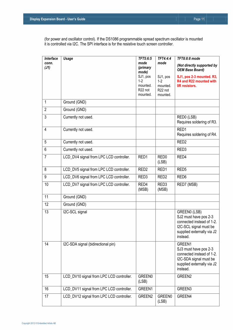
The I2C interface is for controlling the HDMI/DVI transmitters as well as for communicating with the e2prom that contains configuration information. It is also for communicating with the i2c port expander
Display Expansion Board - User’s Guide Page 11
Copyright 2012 © Embedded Artists AB
(for power and oscillator control). If the DS1086 programmable spread spectrum oscillator is mounted it is controlled via I2C. The SPI interface is for the resistive touch screen controller.
Interface conn. (J1)
Usage TFT5:6:5 mode (primary mode) SJ1, pos 1-2 mounted. R22 not mounted.
TFT4:4:4 mode
SJ1, pos 1-2 mounted. R22 not mounted.
TFT8:8:8 mode
(Not directly supported by OEM Base Board)
SJ1, pos 2-3 mounted. R3, R4 and R22 mounted with 0R resistors.
1 Ground (GND)
2 Ground (GND)
3 Currently not used. RED0 (LSB) Requires soldering of R3.
4 Currently not used. RED1 Requires soldering of R4.
5 Currently not used. RED2
6 Currently not used. RED3
7 LCD_DV4 signal from LPC LCD controller. RED1 RED0 (LSB)
RED4
8 LCD_DV5 signal from LPC LCD controller. RED2 RED1 RED5
9 LCD_DV6 signal from LPC LCD controller. RED3 RED2 RED6
10 LCD_DV7 signal from LPC LCD controller. RED4 (MSB)
RED3 (MSB)
RED7 (MSB)
11 Ground (GND)
12 Ground (GND)
13 I2C-SCL signal GREEN0 (LSB) SJ2 must have pos 2-3 connected instead of 1-2. I2C-SCL signal must be supplied externally via J2 instead.
14 I2C-SDA signal (bidirectional pin) GREEN1 SJ3 must have pos 2-3 connected instead of 1-2. I2C-SDA signal must be supplied externally via J2 instead.
15 LCD_DV10 signal from LPC LCD controller. GREEN0 (LSB)
GREEN2
16 LCD_DV11 signal from LPC LCD controller. GREEN1 GREEN3
17 LCD_DV12 signal from LPC LCD controller. GREEN2 GREEN0 (LSB)
GREEN4

Display Expansion Board - User’s Guide Page 12
Copyright 2012 © Embedded Artists AB
18 LCD_DV13 signal from LPC LCD controller. GREEN3 GREEN1 GREEN5
19 LCD_DV14 signal from LPC LCD controller. GREEN4 GREEN2 GREEN6
20 LCD_DV15 signal from LPC LCD controller. GREEN5 (MSB)
GREEN3 (MSB)
GREEN7 (MSB)
21 Ground (GND)
22 Ground (GND)
23 Currently not used. BLUE0 (LSB)
24 Reset input to the board. BLUE1 SJ4 must have pos 2-3 connected instead of 1-2. RESET signal must be supplied externally via J2 instead.
25 LCD_DV18 signal from LPC LCD controller. RED0 (LSB)
BLUE2
26 LCD_DV19 signal from LPC LCD controller. BLUE0 (LSB)
BLUE3
27 LCD_DV20 signal from LPC LCD controller. BLUE1 BLUE0 (LSB)
BLUE4
28 LCD_DV21 signal from LPC LCD controller. BLUE2 BLUE1 BLUE5
29 LCD_DV22 signal from LPC LCD controller. BLUE3 BLUE2 BLUE6
30 LCD_DV23 signal from LPC LCD controller. BLUE4 (MSB)
BLUE3 (MSB)
BLUE7 (MSB)
31 Ground (GND)
32 Ground (GND)
33 Currently not used.
34 Currently not used.
35 Vertical sync (VSYNC). Also called LCD_FP.
36 Pixel data enable signal (DEN). Also called LCD_ENAB.
37 Horistontal sync (HSYNC). Also called LCD_LP.
38 Pixel data clock.
39 Ground (GND)
40 External pixel clock to LCD controller (output signal from the board).
41 +3.3V supply to the board.
42 +5.0V supply to the board.
43 SPI interface, clock signal
44 SPI interface, mosi signal
Display Expansion Board - User’s Guide Page 13
Copyright 2012 © Embedded Artists AB
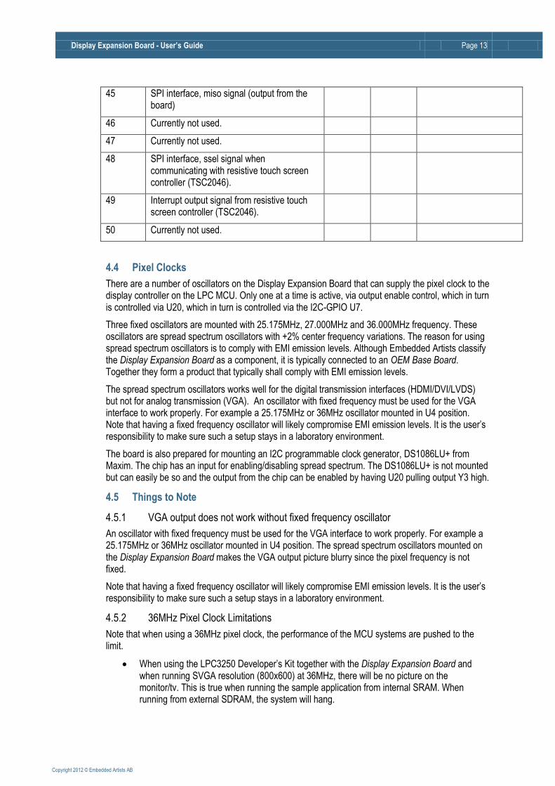
45 SPI interface, miso signal (output from the board)
46 Currently not used.
47 Currently not used.
48 SPI interface, ssel signal when communicating with resistive touch screen controller (TSC2046).
49 Interrupt output signal from resistive touch screen controller (TSC2046).
50 Currently not used.
4.4 Pixel Clocks
There are a number of oscillators on the Display Expansion Board that can supply the pixel clock to the display controller on the LPC MCU. Only one at a time is active, via output enable control, which in turn is controlled via U20, which in turn is controlled via the I2C-GPIO U7.
Three fixed oscillators are mounted with 25.175MHz, 27.000MHz and 36.000MHz frequency. These oscillators are spread spectrum oscillators with +2% center frequency variations. The reason for using spread spectrum oscillators is to comply with EMI emission levels. Although Embedded Artists classify the Display Expansion Board as a component, it is typically connected to an OEM Base Board. Together they form a product that typically shall comply with EMI emission levels.
The spread spectrum oscillators works well for the digital transmission interfaces (HDMI/DVI/LVDS) but not for analog transmission (VGA). An oscillator with fixed frequency must be used for the VGA interface to work properly. For example a 25.175MHz or 36MHz oscillator mounted in U4 position. Note that having a fixed frequency oscillator will likely compromise EMI emission levels. It is the user’s responsibility to make sure such a setup stays in a laboratory environment.
The board is also prepared for mounting an I2C programmable clock generator, DS1086LU+ from Maxim. The chip has an input for enabling/disabling spread spectrum. The DS1086LU+ is not mounted but can easily be so and the output from the chip can be enabled by having U20 pulling output Y3 high.
4.5 Things to Note
4.5.1 VGA output does not work without fixed frequency oscillator
An oscillator with fixed frequency must be used for the VGA interface to work properly. For example a 25.175MHz or 36MHz oscillator mounted in U4 position. The spread spectrum oscillators mounted on the Display Expansion Board makes the VGA output picture blurry since the pixel frequency is not fixed.
Note that having a fixed frequency oscillator will likely compromise EMI emission levels. It is the user’s responsibility to make sure such a setup stays in a laboratory environment.
4.5.2 36MHz Pixel Clock Limitations
Note that when using a 36MHz pixel clock, the performance of the MCU systems are pushed to the limit.
When using the LPC3250 Developer’s Kit together with the Display Expansion Board and when running SVGA resolution (800x600) at 36MHz, there will be no picture on the monitor/tv. This is true when running the sample application from internal SRAM. When running from external SDRAM, the system will hang.

Display Expansion Board - User’s Guide Page 14
Copyright 2012 © Embedded Artists AB
When using the LPC4357 Developer’s Kit together with the Display Expansion Board and when running SVGA resolution (800x600) at 36MHz, there will be minor flickering on the HDMI/DVI output from the TDA19988. No flickering has been observed on the output from the TFP410. It is however likely that the system is running close to the limits.
4.5.3 Limited Driver Functionality for TDA19988
Note that the driver for the TDA19988 has limited functionality. CEC and HDCP are not implemented at all and all registers are not documented in the available documentation. Contact NXP for further information about available driver code for the chip. There exists a Linux driver with full functionality (not provided by Embedded Artists). It is however not a simple task to port this driver to a non-Linux framework.
Implementing a full HDMI compatible interface is an extensive development effort that is out of the scope for this Display Expansion Board. The normal procedure is that the source of the display data negotiates with the monitor about available display formats and then the display source adjust the picture data to comply with the monitor capabilities. In a typical embedded system with an LPC MCU there are limited possibilities to adjust the display data. Instead a fixed (commonly used) setting will always be used.
4.5.4 Picture on Monitors and TV:s
Note that there is no guarantee that pictures can be displayed on tested monitors. The four selected video standards (VGA/SVGA/480p/576p) are common but not all monitors/TV:s support them (especially not SVGA with 56Hz frame rate).
4.5.5 Usage - Evaluation
Note that the Display Expansion Board has not been designed for integration into an end-product. It is for evaluation and prototyping.
4.6 Software Driver
A general software driver has been created to in order to make it simple and non-complex to work with different displays. This section contains a very brief description of the structure. The code is the general documentation in itself, simply because the software will likely be updated.
The description below assumes that the LPC1788 Developer’s Kit is used. The software is easily ported to other kits as well, like the LPC3250 v2, LPC4088 and LPC4357 Developer’s Kits.
The software driver package (a zip-file) is downloaded from Embedded Artists support page for the Display Expansion Board. The support site is available after registration of the product serial key that comes with purchase of a Display Expansion Board. The package shall be unzipped in the same directory as the sample applications for the LPC1788 Developer's Kit. The default name of that directory is oem_lpc1788. The sample application is called s_display_exp_board.
There is a support library called Lib_Displays. The code in this library contains all low-level details.
The I2C-E2PROM contains configuration information. The I2C address of the memory is 0x56 (1.0.1.0.1.1.0.RW). An application can begin with detecting if an I2C-E2PROM is present on this address. If so, an Display Expansion Board is attached to the system and the LCD controller and graphical application can be started.
Some of the parameters are just to copy directly into the LCD controller of the LPC processors. Other information is stored in readable command strings. The configuration information stored is:
Magic number to detect that information has been stored.
Name of LCD and manufacturer in readable strings.
LCD controller setup, including timing parameters. Can be directly copied to LCD controller registers.

Display Expansion Board - User’s Guide Page 15
Copyright 2012 © Embedded Artists AB
Init sequence command string. The string must be interpreted by the software driver.
Power down command string. The string must be interpreted by the software driver.
Parameters related to touch screen.
The general structure of an application utilizing the Display Expansion Board can be found in main() in main.c of the s_display_exp_board sample application. A call to ea_lcdb_open(…) will read the configuration e2prom and initialize the application. A call to ea_lcdb_getLcdParams(..) will get the retrieved parameters, where the main parameters are width and height of the display.
4.6.1 Settings for VGA (640x400 px, 60Hz)
The code listing below contains the LCD controller settings for the controller that is used on many LPC processors.
static const LCD_PARAM_T vga_60hz = { 48, /* Horizontal back porch = 1.92 us */ 16, /* Horizontal front porch = 640 ns */ 96, /* HSYNC pulse width = 3.84us */ 640, /* Pixels per line */ 29, /* Vertical back porch */ 10, /* Vertical front porch */ 2, /* VSYNC pulse width */ 480, /* Lines per panel */ 0, /* Do not invert output enable */ 1, /* Invert panel clock */ 1, /* Invert HSYNC */ 1, /* Invert VSYNC */ 1, /* AC bias frequency (not used) */ 16, /* Bits per pixel */ 0, /* Optimal clock rate (Hz). Use external 25.175MHz clock */ TFT, /* LCD panel type */ 0, /* Single panel display */ };
4.6.2 Settings for SVGA (800x600 px, 56Hz)
The code listing below contains the LCD controller settings for the controller that is used on many LPC processors.
static const LCD_PARAM_T svga_800x600_36MHz_56Hz = { 128, /* Horizontal back porch */ 24, /* Horizontal front porch */ 72, /* HSYNC pulse width */ 800, /* Pixels per line */ 22, /* Vertical back porch */ 1, /* Vertical front porch */ 2, /* VSYNC pulse width */ 600, /* Lines per panel */ 0, /* Do not invert output enable */ 1, /* Invert panel clock */ 1, /* Invert HSYNC */ 1, /* Invert VSYNC */ 1, /* AC bias frequency (not used) */ 16, /* Bits per pixel */ 0, /* Optimal clock rate (Hz). Use external 36MHz clock */ TFT, /* LCD panel type */ 0, /* Single panel display */ };

Display Expansion Board - User’s Guide Page 16
Copyright 2012 © Embedded Artists AB
4.6.3 Settings for 480p (720x480 px, 60Hz)
The code listing below contains the LCD controller settings for the controller that is used on many LPC processors.
static const LCD_PARAM_T _720x480_27_027MHz_60Hz = { 60, /* Horizontal back porch */ 16, /* Horizontal front porch */ 62, /* HSYNC pulse width */ 720, /* Pixels per line */ 30, /* Vertical back porch */ 9, /* Vertical front porch */ 6, /* VSYNC pulse width */ 480, /* Lines per panel */ 0, /* Do not invert output enable */ 1, /* Invert panel clock */ 1, /* Invert HSYNC */ 1, /* Invert VSYNC */ 1, /* AC bias frequency (not used) */ 16, /* Bits per pixel */ 0, /* Optimal clock rate (Hz). Use external 27MHz (27.027MHz) clock */ TFT, /* LCD panel type */ 0, /* Single panel display */};
4.6.4 Settings for SVGA (720x576 px, 50Hz)
The code listing below contains the LCD controller settings for the controller that is used on many LPC processors.
static const LCD_PARAM_T _720x576_27MHz_50Hz = { 66, /* Horizontal back porch */ 16, /* Horizontal front porch */ 62, /* HSYNC pulse width */ 720, /* Pixels per line */ 34, /* Vertical back porch */ 9, /* Vertical front porch */ 6, /* VSYNC pulse width */ 576, /* Lines per panel */ 0, /* Do not invert output enable */ 1, /* Invert panel clock */ 1, /* Invert HSYNC */ 1, /* Invert VSYNC */ 1, /* AC bias frequency (not used) */ 16, /* Bits per pixel */ 0, /* Optimal clock rate (Hz). Use external 27MHz clock */ TFT, /* LCD panel type */ 0, /* Single panel display */ };

Display Expansion Board - User’s Guide Page 17
Copyright 2012 © Embedded Artists AB
5 Further Information The datasheet of the main components used can be downloaded on the support page (requires registering of product serial key on Embedded Artists’ web site).
Always check for the latest information/version on the support page.


![Outcome of Board Meeting - MSR India Big Expansion Plan [Board Meeting]](https://img.dokumen.tips/doc/110x75/577ca7031a28abea748c2690/outcome-of-board-meeting-msr-india-big-expansion-plan-board-meeting.jpg)