Embed Size (px)
Citation preview


Director and State Geologist Wallace Ulrich
First printing of 150 copies by Citizen Printing Company, Inc., December 2011.
The Shirley Basin Mine and the Development of the Roll-Front Model of Uranium Ore Deposits: A His-torical Perspective
Wyoming State Geological Survey (WSGS) Memoir 6, 2011.ISBN 978-1-884589-58-4
Copyright © 2011 by the Wyoming State Geological Survey. All rights reserved.
The WSGS encourages fair use of its material. We request that credit be expressly given to the “Wyoming State Geological Survey” when citing information from this publication. Please contact the WSGS at (307) 766-2286, ext. 224, or by email at [email protected], if you have any questions about citing materials, preparing acknowledgments, or extensive use of this material. We appreciate your cooperation.
Any use of trade, product, or firm names in this publication is for descriptive purposes only and does not imply endorsement or approval by the State of Wyoming or the WSGS. Individuals with disabilities who require an alternate form of this publication should contact the WSGS. TTY relay operator 800-877-9975.
For additional information about the WSGS or to order publications and maps, log on to www.wsgs.uwyo.edu, call (307) 766-2286, ext. 224, or email [email protected].
Editing, design, and layout by:Chamois L. Andersen
Shirley Basin Mine, facing northeast toward the Laramie Range, east-central Wyoming, February 1962. Temperature about 22 degrees Celsius (30 degrees F) below zero. Visible is the underground mine headframe with vapor from heating units in the building along with (nearer the photographer) vapor plumes from ventilation fans, which were installed on ventilation shafts to the underground workings below the surface. Photo by R.V. Bailey.
The Shirley Basin Mine and the Development of the Roll-Front Model of Uranium Ore Deposits: A Historical PerspectiveWyoming State Geological Survey Memoir 62011R. V. Bailey and Robert W. Gregory
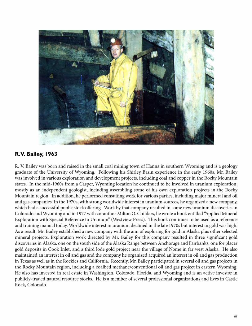
R.V. Bailey, 1963
R. V. Bailey was born and raised in the small coal mining town of Hanna in southern Wyoming and is a geology graduate of the University of Wyoming. Following his Shirley Basin experience in the early 1960s, Mr. Bailey was involved in various exploration and development projects, including coal and copper in the Rocky Mountain states. In the mid-1960s from a Casper, Wyoming location he continued to be involved in uranium exploration, mostly as an independent geologist, including assembling some of his own exploration projects in the Rocky Mountain region. In addition, he performed consulting work for various parties, including major mineral and oil and gas companies. In the 1970s, with strong worldwide interest in uranium sources, he organized a new company, which had a successful public stock offering. Work by that company resulted in some new uranium discoveries in Colorado and Wyoming and in 1977 with co-author Milton O. Childers, he wrote a book entitled “Applied Mineral Exploration with Special Reference to Uranium” (Westview Press). This book continues to be used as a reference and training manual today. Worldwide interest in uranium declined in the late 1970s but interest in gold was high. As a result, Mr. Bailey established a new company with the aim of exploring for gold in Alaska plus other selected mineral projects. Exploration work directed by Mr. Bailey for this company resulted in three significant gold discoveries in Alaska: one on the south side of the Alaska Range between Anchorage and Fairbanks, one for placer gold deposits in Cook Inlet, and a third lode gold project near the village of Nome in far west Alaska. He also maintained an interest in oil and gas and the company he organized acquired an interest in oil and gas production in Texas as well as in the Rockies and California. Recently, Mr. Bailey participated in several oil and gas projects in the Rocky Mountain region, including a coalbed methane/conventional oil and gas project in eastern Wyoming. He also has invested in real estate in Washington, Colorado, Florida, and Wyoming and is an active investor in publicly-traded natural resource stocks. He is a member of several professional organizations and lives in Castle Rock, Colorado.
iii
Acknowledgements This publication is based on the report entitled “Written and Pictorial Description of Geology Observed in the Shirley Basin Mine,” prepared by co-author R. V. Bailey in January 1964 when he was employed by Utah Construction and Mining Company at the Shirley Basin Mine in Carbon County, Wyoming.
Geologist Robert E. Melin launched the underground mapping program and was instrumental in the development of many of the mapping techniques. The the authors acknowledge the support of R. I. Rackley, who served as District Geologist at the time and for which the success of the geologic program at the Shirley Basin Mine was in large part due to his thoughtfulness and guidance. The late Mack Tilley, manager of the Shirley Basin underground uranium mine, was very helpful with providing encouragement for the geological mapping in the mine. In 2010, geologist Matt Cunningham was instrumental in converting data from an earlier primitive form into data, which can be used in computer programs. Mr. Cunningham also constructed an early draft of the maps and cross sections included in this publication.
The uranium ore occurrences described in this publication were mined initially by underground methods and later by attempts to perform in-situ leaching followed by open pit operations. Thus, much of the ore shown herein has been mined and processed. Accordingly, there is no confidential information on the company contained in this paper and this has allowed the use of ore grades and thicknesses, an important component of this presentation. The authors would like to thank Bernard Bonifas, manager of the Areva, Inc. (previously Cogema) office in Casper, Wyoming as well as Areva engineer Mark Owens for their help and cooperation. Areva acquired the Shirley Basin properties earlier held by Utah Construction in Shirley Basin and now holds those records that remain of the Shirley Basin operations. We would like to thank them for the use of the records. The authors also acknowledge James Rodgers, Tim Sprague, Robin Lyons, and Phyllis Ranz of the Wyoming State Geological Survey for the graphics and illustrations featured in the publilcation, and Brendon Orr for the design and layout.
iv

ContentsAbstract . . . . . . . . . . . . . . . . . . . . . . . . . . . . . . . . . . . . . . . . . . . . . . . . . . . 1Introduction . . . . . . . . . . . . . . . . . . . . . . . . . . . . . . . . . . . . . . . . . . . . . . . 1Stratigraphy . . . . . . . . . . . . . . . . . . . . . . . . . . . . . . . . . . . . . . . . . . . . . . . 3Fossils . . . . . . . . . . . . . . . . . . . . . . . . . . . . . . . . . . . . . . . . . . . . . . . . . . . . . 3Structure . . . . . . . . . . . . . . . . . . . . . . . . . . . . . . . . . . . . . . . . . . . . . . . . . . 3Uranium Source . . . . . . . . . . . . . . . . . . . . . . . . . . . . . . . . . . . . . . . . . . . 4Mining Techniques . . . . . . . . . . . . . . . . . . . . . . . . . . . . . . . . . . . . . . . . . 4The Mapping Program . . . . . . . . . . . . . . . . . . . . . . . . . . . . . . . . . . . . . . 4
A Ore Body . . . . . . . . . . . . . . . . . . . . . . . . . . . . . . . . . . . . . . . . . . . . . . . . . . . . . . . . . . . . . . . . . . . 5Al Drift . . . . . . . . . . . . . . . . . . . . . . . . . . . . . . . . . . . . . . . . . . . . . . . . . . . . . . . . . . . . . . . . . . . . . . . 6B5 Winze and Drift . . . . . . . . . . . . . . . . . . . . . . . . . . . . . . . . . . . . . . . . . . . . . . . . . . . . . . . . . . . 8Stopes North of A7 Drift . . . . . . . . . . . . . . . . . . . . . . . . . . . . . . . . . . . . . . . . . . . . . . . . . . . . . . 8A6 Drift . . . . . . . . . . . . . . . . . . . . . . . . . . . . . . . . . . . . . . . . . . . . . . . . . . . . . . . . . . . . . . . . . . . . . . 10A7 Drift . . . . . . . . . . . . . . . . . . . . . . . . . . . . . . . . . . . . . . . . . . . . . . . . . . . . . . . . . . . . . . . . . . . . . . 12A420 Through A428 Stopes . . . . . . . . . . . . . . . . . . . . . . . . . . . . . . . . . . . . . . . . . . . . . . . . . . 15South of A7 Drift . . . . . . . . . . . . . . . . . . . . . . . . . . . . . . . . . . . . . . . . . . . . . . . . . . . . . . . . . . . . . 15A454 – A456 Stopes . . . . . . . . . . . . . . . . . . . . . . . . . . . . . . . . . . . . . . . . . . . . . . . . . . . . . . . . . . 20A9 Drift . . . . . . . . . . . . . . . . . . . . . . . . . . . . . . . . . . . . . . . . . . . . . . . . . . . . . . . . . . . . . . . . . . . . . 20A448, A451, and A460 Stopes . . . . . . . . . . . . . . . . . . . . . . . . . . . . . . . . . . . . . . . . . . . . . . . . . 21A458 - A461 Scrams . . . . . . . . . . . . . . . . . . . . . . . . . . . . . . . . . . . . . . . . . . . . . . . . . . . . . . . . . . 21A13 Drift . . . . . . . . . . . . . . . . . . . . . . . . . . . . . . . . . . . . . . . . . . . . . . . . . . . . . . . . . . . . . . . . . . . . . 23
Major Observed Mineral Features . . . . . . . . . . . . . . . . . . . . . . . . . . 24Recent Work Performed . . . . . . . . . . . . . . . . . . . . . . . . . . . . . . . . . . . 24Summary of Recent Work . . . . . . . . . . . . . . . . . . . . . . . . . . . . . . . . . . 26Findings . . . . . . . . . . . . . . . . . . . . . . . . . . . . . . . . . . . . . . . . . . . . . . . . . . 26Conclusion . . . . . . . . . . . . . . . . . . . . . . . . . . . . . . . . . . . . . . . . . . . . . . . 26CD Maps and Cross Sections . . . . . . . . . . . . . . . . . . . . . . . . . . . . . . . 27
v
1
Abstract
In the early 1960s, geologists working in the Shirley Basin Mine in east central Wyoming were the first to critically examine in detail a sandstone-hosted uranium deposit through underground workings, with the purpose of determining the process of uranium emplacement in groundwater saturated strata. After careful observations in the underground mine, along with detailed mapping and the construction of cross sections, the now accepted and useful exploration tool, the roll-front model of uranium ore deposition, was formulated and subsequently proven for use by the uranium exploration and mining industry.
In the Shirley Basin high-grade ore was mined underground from poorly consolidated sand and gravel deposits of the Lower Eocene Wind River Formation in the early 1960s. These shallow sands, at depths of less than 115 meters (380 feet) were named the Sage Sand and the Turtle Sand. At the time of mineralization, groundwater transporting uranium in solution was generally moving from south to north, opposite of the current groundwater movement direction. The sands and gravels were and remain saturated with groundwater, and the unstable ground and abundant water together created difficult underground mining conditions. The use of “square set” mining techniques was required in order to accomplish ore removal under these conditions. A geologic mapping program, carried out in the underground workings, accompanied by detailed drill hole logging and geologic
cross section construction, revealed habits and relationships of the mineralization and associated alteration. Mineralization and ore were found to lie along the periphery of tongues of “altered” ground. The greenish to rusty altered ground was usually recognizable in hand specimen and represented ‘leached’ ground through which mineralizing solutions had passed. The major tongue of alteration was found to be as much as 21 meters (70 feet) thick, tens of meters (hundreds of feet) across, and several kilometers long. The best ore occurred on what came to be called rolls or roll fronts (geochemical interfaces) at the terminal edges of altered ground, and additional ore was found to occur in “subsidiary” rolls on the upper and lower surfaces of the altered ground. The results of the mapping program provided data for improved planning for mining operations as well as more effective exploration and
development drilling. Concerning the nature of uranium deposits in sandstone, the results of the studies in 1962 and 1963 at the Shirley Basin Mine were first, the concept of uranium concentrations at a geochemical interface and second, the development of the roll-front model of uranium deposits. This was a major breakthrough in knowledge and for understanding the nature of uranium deposits, particularly in sandstone deposits. The roll-front model was successfully applied to exploration and development drilling, to ore projections ahead of mine workings, and to reserve estimates in the Shirley Basin Mine. Subsequently, it has been used worldwide for understanding this type of deposit.
Introduction
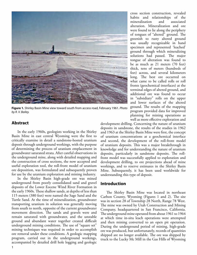
The Shirley Basin Mine was located in northeast Carbon County, Wyoming (Figures 1 and 2). The site was in section 28 of Township 28 North, Range 78 West. The mine was owned by Utah Construction and Mining Company, headquartered in San Francisco, California. The underground mine operated from about 1961 to 1964 at which time in-situ leach operations were attempted and then mining converted to an open pit operation. During the underground period of mining, high-grade ore was produced, but unfortunately, records of quantities shipped are no longer available. The ore was shipped by truck to the Lucky Mc Mill in the Gas Hills of Wyoming
Figure 1. Shirley Basin Mine view toward south from access road, February 1961. Photo by R. V. Bailey.

2
(also owned by Utah Construction) and averaged 0.70% U3O8. The ore bodies at the underground mine site were within the Eocene Wind River Formation at depths of about 86 meters (280 feet), to approximately 115 meters (380 feet) below the surface. From a geologic viewpoint, the amazing continuity of the host sands provided an excellent situation for the development of geochemical reaction zones at the interface between invading oxidized waters and reduced conditions in unoxidized sands. The underground mine provided an outstanding opportunity to study the uranium deposits in detail.
The following description and accompanying maps and cross sections have been prepared to describe and illustrate ore body configuration and major geological features observed in the course of the mapping program in the Shirley Basin underground uranium mine. In addition, a brief review of mining techniques and a discussion of mapping technique evolution are presented. The description is presented from an historical approach, with the first stope mined described first. Extensive use has been made of color photographs taken in the mine as they describe better than words, the appearance of mineralized and non-mineralized features. The underground photographs are enlargements of 35 mm transparencies taken with flash attachment and daylight-type Kodachrome® film by co-author R. V. Bailey.
Detailed information concerning mine location, history, structure, stratigraphy, and one possibility of the ore geochemistry (subsequently disproved) is discussed in a paper by Robert E. Melin (1964). In this report, these topics are only briefly mentioned. The paper can be found on the CD of Economic Geology uranium publications of the early 1960s, available from the Society of Economic Geologists.
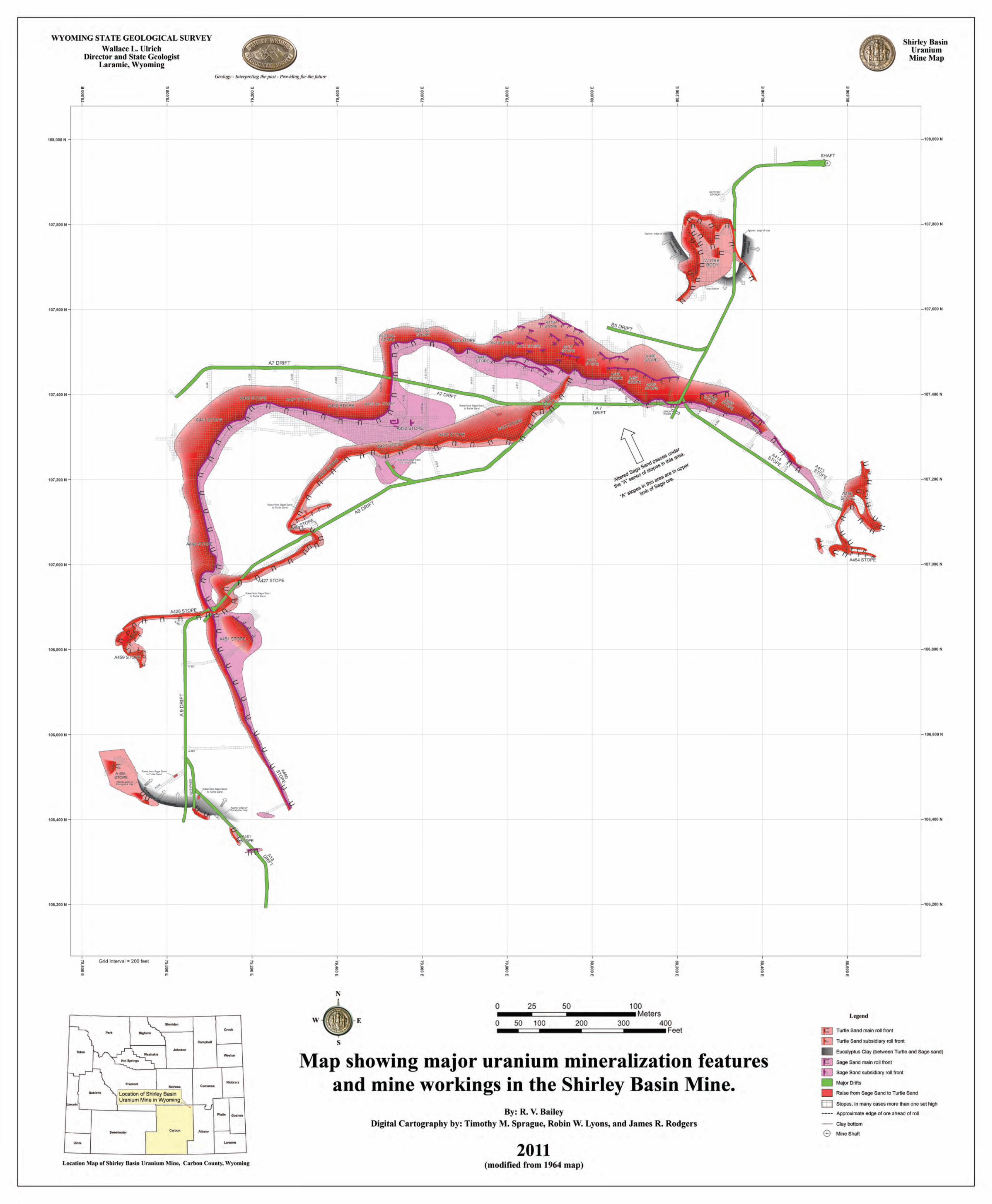
On the accompanying maps, major geological features observed in the mine have been plotted as found in the stopes, as well as possible edges of the ore both within and outside the stopes. For this report, mineralization projections have been carried beyond the stope areas utilizing electric and sample description logs from drill holes with the objective to illustrate the nature and configuration of the roll front deposits and the bodies of alteration in which they are related.
Because this is a report on geology observed in the Shirley Basin Mine, the introduction would be incomplete without a
statement about the working environment in which the geological mapping program was conducted. Plans in 1958 and 1959 called for the exploration department of the company to withdraw from Shirley Basin shortly after exploration and initial development drilling were completed. This timing coincided with the completion of the shaft and the beginning of mining. However, when drifting was underway and mining was about to begin, a wise decision was made to keep exploration department geologists on the job to conduct underground mapping and to act in an advisory or consulting capacity to the mine operating personnel while still reporting to the exploration department in Salt Lake City, Utah as well as the corporate headquarters in San Francisco, California. Ultimately, exploration department representation at Shirley Basin was reduced to one geologist, R. V. Bailey.
The geological staff at Shirley Basin, primarily author R. V. Bailey, who was the mine geologist, acquired a very intimate and useful familiarity with the altered ground, ore occurrences, and related phenomena. Mr. Bailey attributes much of the familiarity with these uranium deposits to the fact that the mapping was carried out underground where close and careful examination could be made of the geological features without problems such as heavy equipment hazards that often are associated with
Figure 2. Shirley Basin Mine looking northeast toward the Laramie Range from Moss Agate Hill, February 1962. The temperature is well below zero and condensed moisture can be seen at the top of the head frame. The plumes from the small buildings are caused by exhaust moisture from heaters used to heat ventilation air for the mine. These two buildings are located at the surface site of cased escape-ventilation holes which intersect drifts underground. Photo by R. V. Bailey.

3
mapping in an open pit mine. In addition, temperature, air movement, and humidity underground are much more conducive to detailed geological work than an open pit operation. A camp was established a short distance from the mine and a group of mobile homes was assembled for the staff. The mine geologist and his family also lived in the camp.
To aid mining and mine planning, the geological staff placed current geologic maps and cross sections in the engineering office where they were available for study by operations personnel. The mine geologist frequently prepared special additional (not requested) studies, such as permeability maps for the location of water wells for the camp water supplies. Maps and reports showing roll trends, ore locations, and proposed drilling sites were often submitted directly to mine manager Mack Tilley. Roll front projections were crucial in selecting drill hole locations and were also crucial in mine planning. The mine geologist provided important contributions to the mining operation, as well as a great deal of information about uranium roll front emplacement, ore location size and configuration, and information on the relationship of unaltered to altered ground was gathered.
Stratigraphy
In the underground mine high-grade ore, which consisted of black (uraninite-coated) sand and gravel, was mined from two poorly consolidated sand horizons in the Lower Eocene Wind River Formation. These two near-surface sands, less than 115 meters (380 feet) below the surface, were named the Sage Sand and the Turtle Sand. At some time after deposition the sands were saturated with moving, uranium-rich groundwater. The sands were arkosic (derived from granite) and apparently were eroded from the Shirley Mountains to the southwest and the Sweetwater area to the northwest, as well as the Laramie Mountains to the east and southeast. The terms sand, gravel, and clay came to be used in describing the Shirley Basin sediments rather than sandstone, conglomerate, or shale because of the uncemented and unconsolidated character of the sediments.
The underground mining operations were conducted within two distinct and named lithologic units. The most important unit is the Sage Sand because it contains the most ore in sec. 28, T. 28 N., R. 78 W. This unit is about 21 meters (70 feet) thick and consists of a coarse, gravelly lower zone and a coarse to silty upper zone, with ore occurring locally in both. Immediately above the Sage Sand is the Eucalyptus Clay unit. This clay is 3 to 4.5 meters (10 to 15 feet), thick and very persistent. In only a few places has it been scoured out or penetrated by streams, which deposited the overlying sand and gravel unit, the Turtle Sand. The Eucalyptus Clay was named
for the tentative identification of fossils that appeared to resemble eucalyptus leaves. The locally ore-bearing sand and gravel unit above the Eucalyptus Clay was named the Turtle Sand because of the abundance of fossil turtle shells, which were about the size of large frisbees. The Turtle Sand is about 5 meters (17 feet) thick and grades upward into a silt and then clay. More detailed lithologies of these units are contained in the paragraphs describing the various stopes and drifts.
As revealed by drilling information, within the mine area the sands generally terminate to the northeast against a subcrop formed by a resistant Cretaceous sand unit and crop out to the south and southwest. Both the sands and the clays in the mine area are remarkably continuous and uniform laterally, a feature that has allowed the development of very continuous mineralization features in the Shirley Basin Mine uranium deposits. This greatly facilitated the study of the deposits, particularly because the mapping was carried out underground. No faulting or folding was present to complicate the geology.
Fossils
Fossil turtle shells about the size of large frisbees have been found both in mineralized and non-mineralized ground in the mine, but particularly in the Turtle Sand in the A461 Stope. Fossil leaves have been found in abundance in a silty section at the bottom of the Eucalyptus Clay. A tooth, possibly alligator, was also recovered from a drill core taken for chemical testing of ore grades northwest of the shaft. No other fossils were found.
Structure
The Wind River Formation dips less than two degrees northeast throughout most of the Shirley Basin. Drilling results suggest a slight northwest dip to the strata in the Shirley Basin Mine. Cretaceous sediments underlying the Wind River Formation dip about five degrees southwest. No faults have been encountered in the Shirley Basin Mine and drilling in several nearby sections suggests the presence of none. No faults were suggested on aerial photographs of the mine area. It appears that the streams that deposited the sand and gravel that hosted the uranium deposits were flowing generally from south to north, the same direction the mineralizing waters followed. However, at some point, the direction of groundwater movement changed and current groundwater movement appears to be to the south, probably due to the influence of the Little Medicine Bow River (actually a small stream) that flows to the south. Erosion has also removed a large amount of sediment to the south, while to the north the topography rises substantially.
4
Uranium Source
The source of the uranium found in Shirley Basin is obscure. There are no known significant or obvious sources such as high-grade deposits in nearby igneous rocks. However, the Granite Mountains have been shown to have lost a significant amount of uranium in the recent as well as distant geologic past (Stuckless and Nkomo, 1978; Stuckless, et al., 1981). Alternatively, some favor the idea that Tertiary-aged volcanic tuffs contained significant concentrations of uranium and is responsible for the uranium deposits in Wyoming’s basins (Love, 1954; Denson, 1959). During surface weathering and oxidation, uranium contained in the ash would be taken into solution and thus mobilized could migrate down into the aquifers in the underlying Eocene Wind River Formation. Uranium in the arkosic sands in the Eocene beds, generated from the weathering of nearby igneous rocks containing trace amounts of disseminated uranium, may have made a minor contribution to the ore deposits. As a working hypothesis, the authors believe that some combination of the two provided the uranium for deposits such as those of the Shirley Basin.
Mining Techniques Because of the loose and unconsolidated character of the sediments in the Shirley Basin Mine, underground mining was carried out entirely by the squareset method. The squaresets were framed by heavy wooden beams and for the most part did not exceed 1.5 x 1.5 x 1.5 meters (5 x 5 x 5 feet). Drifting was carried out with extensive overhead spiling and closely spaced wall lagging. Water flowing into the drift from the advancing face was a constant problem.
Ideally, underground mining should be carried out by driving a drift or haulageway to the furthest edge of ore, with subsequent retreat stoping. At the Shirley Basin Mine this was not done because of the immediate need for ore production. Almost as soon as the first drift (Al Drift) reached the vicinity of what became known as the A Ore Body, stoping was started. Such a procedure in unconsolidated sediments has adverse effects on the drifts because of ground movement, which follows closely behind the stoping.
The water table was about 30 meters (100 feet) below the surface prior to pumping or excavation. Although an effort was made to lower the water table sufficiently to permit mining of ore in the lower part of the Sage Sand unit when mining commenced, water was found to be too abundant and too fast moving to permit economical mining of the deeper ore. The concrete-lined shaft was initially sunk to the bottom of the Sage Sand at a depth of about 115 meters (380 feet), but the amount of water
was too much to handle so the shaft bottom was plugged back with cement to about 98 meters (320 feet) below the surface. Some of the deeper ore in the Sage Sand is nearer the shaft; however, because of the water it had to be bypassed in favor of the shallower but more distant ore. Several dewatering wells had been drilled in the vicinity of the shaft and it was estimated that these wells were pumping about 13,600 liters (3,000 gallons) per minute. The Wind River Formation, as expected, was found to be an excellent aquifer and this characteristic clearly played a crucial role in the earlier invasion of oxygenated water and the formation of uranium ore bodies.
The Al Drift was driven its entire length in the coarse to silty upper part of the Sage Sand. The uniformity of the grain size is quite remarkable for a fluvial sand system. The results of the initial drifting from the mine shaft, initially west and then turning south, suggested that water at this level in the Shirley Basin Mine might present no significant difficulties because for more than 30 meters (100 feet) from the shaft, the sands were wet but not bleeding water. This no doubt was largely due to the pumps creating a cone of depression around the shaft. Perched water encountered at the edge of a scour of the Turtle Sand through the Eucalyptus Clay about 52 meters (170 feet) from the shaft, posed some problems but no additional significant water hazards were encountered in driving the drift for the next 61 meters (200 feet). However, once the cone of depression was penetrated by drifts and stopes further from the shaft, the floor and all working faces dripped and sometimes ran water continuously until the water level in that particular area was drained below the workings.
Underhanded mining (below the haulage drift level) was utilized, but could be carried out only when the water level was lowered below, or almost below the stopes. Electrical power was generated on site and there were some nervous times when the water pumps stopped functioning in the mine for one reason or another. In the absence of pumping water soon began rising into the mine workings and up the shaft. On more than one occasion when the electrical power failed, the pumps stopped and there was no power to the hoist in the shaft so it was not available. The miners and the mine geologist had to climb a ladder up the shaft to escape the rising water. This is the equivalent of climbing a ladder on the side of a 32-story building in total darkness except for a headlamp.
The Mapping Program
Logging of lithologies encountered when the shaft was being sunk was carried out by mining department personnel. At that time several geologists representing the company’s exploration department were busy planning and carrying out exploration drilling. A decision was
5
made that exploration department geologists would undertake an underground geological mapping program for two primary purposes: 1) to assist operating personnel in planning and carrying out an efficient mining plan; and 2) to learn the habits and nature of Shirley Basin Mine uranium mineralization so the knowledge gained could be used to further uranium exploration efforts at Shirley Basin and elsewhere. A geologic mapping program was initiated at the commencement of drift driving. Because mapping in an underground uranium mine in Tertiary sediments of this type was practically unknown to the industry, entirely new concepts and techniques had to be developed. No one had any idea what the ore would look like (except from cores), how the ore would be related to barren ground, how the uranium was transported, or if geological mapping would significantly contribute to either a more effective exploration or mining program.
A great amount of detail resulted from the initial geologic mapping. Maps and cross sections were made at a scale of 1:60 (1 inch = 5 feet) and even larger scales were attempted. Cross sections were made at intervals of roughly 6 meters (20 feet) and multi-level mapping was carried out at a vertical spacing of about 1.5 meters (5 feet), which amounted to a map for each of the five floors (squareset levels) in the initial stope. Mining engineers’ maps showed each squareset mined and these maps made it quite convenient for the geologist to plot the geology observed in the walls, back, or floors in each series of sets. After several entries had been made into the A Ore Body and after stoping had exposed several hundred feet of mine wall, it became apparent that some of the barren ground immediately adjacent to the high-grade ore had a pale to strong rusty to green color. This color or staining was later found to be an extremely significant and valuable guide to the occurrence of mineralization and ore. On the surface above the mine, sand and gravel colors were often difficult to determine from rotary drill cuttings as observed by the geologists. Usually a hand lens was used in the examination of cuttings in order to prepare lithologic descriptions of the wet samples, and this was a challenge particularly during winter months on the Shirley Basin, with strong winds and cold temperatures. The cuttings, of necessity, were mixed with drilling mud, which tends to obscure the sample colors.
In the early stages of mining, several avenues of geological work converged to point out how and why the rusty stain (later called alteration) could be used as an indicator of mineralization and possibly ore. These avenues included: 1) detailed field logging of drill cuttings, 2) construction of detailed geologic cross sections from resistance logs and hand written sample descriptions, 3) improvement of detailed notation of gamma logs, and 4) detailed geologic observations in the mine itself. The detailed geologic cross sections, constructed at a scale of
1:240 (1 inch = 20 feet), were found to be particularly helpful in understanding the large-scale mineralization habits and contributed other clues to the nature of the ore occurrence. This basic geologic work resulted in significant improvements in the geologic mapping techniques, which will be discussed later.
A Ore Body
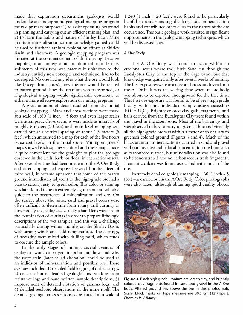
The A Ore Body was found to occur within an erosional scour where the Turtle Sand cut through the Eucalyptus Clay to the top of the Sage Sand, but that knowledge was gained only after several weeks of mining. The first exposures were in a raise and crosscut driven from the Al Drift. It was an exciting time when an ore body was about to be exposed underground for the first time. This first ore exposure was found to be of very high grade locally, with some individual sample assays exceeding 10.0% U3O8. Brightly colored clay galls, fragments, and balls derived from the Eucalyptus Clay were found within the gravel in the scour zone. Most of the barren ground was observed to have a rusty to greenish hue and virtually all the high-grade ore was within a meter or so of rusty to greenish colored ground (Figures 3 and 4). Much of the black uranium mineralization occurred in sand and gravel without any observable local concentration medium such as carbonaceous trash, but mineralization was also found to be concentrated around carbonaceous trash fragments. Hematitic calcite was found associated with much of the ore.
Extremely detailed geologic mapping 1:60 (1 inch = 5 feet) was carried out in the A Ore Body. Color photographs were also taken, although obtaining good quality photos
Figure 3. Black high grade uranium ore, green clay, and brightly colored clay fragments found in sand and gravel in the A Ore Body. Altered ground lies above the ore in this photograph. Scale: black marks on tape measure are 30.5 cm (12”) apart. Photo by R. V. Bailey.

6
was difficult due to wall lagging covering many of the exposures. It was thought at the time that gathering a large amount of initial detail might avoid costly omission of data that would later prove to be important.
The real significance of altered ground and mineralization features was not recognized until mining in the A Ore Body was near completion. On the basis of the sections and maps compiled, the locations and elevations of mineralized features were later plotted on the A Ore Body maps. It was noted that there were some “C” shaped features and a name was needed for descriptions. Someone had read a report by the U.S. Geological Survey on uranium deposits in the Colorado Plateau area and the author therein had used the term “rolls” to describe “C” shaped features. That term was adopted for use with the features seen in the Shirley Basin Mine. Later the term “front” was added so the term became “roll front.”
Mapping revealed that the A Ore Body occurred in a channel area where streams that deposited the Turtle Sand had scoured away a portion of Eucalyptus Clay and had cut down into the Upper Sage Sand. The ore body was formed in the channel by mineralization directly related to what was later recognized as the major Turtle Sand geochemical roll front. Mineralization associated with this front also combined or commingled with mineralization on the upper limb of the underlying Sage Sand front, but it appeared that alteration was not continuous from one sand down to the other. However, the mineralization associated with the Turtle Sand roll front could have tied in with the underlying major roll front in the Sage Sand, but there was no opportunity to verify this concept.
“Normal” and “abnormal” colors were recognized for the sands as well as the clays. The Sage Sand was typically light gray except where it had been affected by
the mineralizing and oxidizing groundwater. The Turtle Sand was also normally a gray color. The oxidized-appearing sands, later called “altered sands,” were rusty to greenish. The clay was normally gray-green, but the color of isolated fragments of it, too, could be changed by the mineralizing solutions, as evidenced by clay fragments and balls containing red colors found in the A Ore Body.
A1 Drift
The A1 Drift was driven 128 meters (420 feet) past the A Ore Body and remained within a persistent coarse to silty gray sand. The drift penetrated ore within the Upper Sage Sand near what was then the south end of the drift and it was interesting to find that after passing through the ore, the drift entered a rusty-colored silty sand in distinct contrast to the earlier gray sand through which it had been driven. Except for the grain size difference, the rusty staining here was recognized as identical to the staining exposed in the A Ore Body. The rusty altered ground in Al was overlain by a thin zone of uranium mineralization, and this in turn was overlain by normal gray unaltered ground just under the Eucalyptus Clay. Thus, the concept of mineralization concentration at the altered-unaltered contact was found to hold true. However, the evidence began to suggest that practically no uranium mineralization would be found anywhere in these sands except directly associated with the contact between altered and unaltered sand. The rusty looking
Figure 4. Colorful clay fragments (balls) in both altered and unaltered ground. The black zone of high grade uranium mineralization surrounds altered ground in the upper right-hand corner. Photo by R. V. Bailey.
Figure 5. Rusty altered ground in lower part of the photograph is overlain by a thin band of black uraninite mineralization. The contact between altered ground and mineralization is very sharp, but the minerialization fades gradually into overlying gray unaltered ground. Cross bedding in the Shirley Basin deposits typlically has little or no effect on mineralized zone location; as shown in this photograph the cross bedding is dipping left and the mineralization is dipping right. Scale: black marks on tape measure are 30.5 cm (12”) apart. Photo by R. V. Bailey.

7
sand and gravel clearly appeared to be oxidized or “altered” as it came to be called, while the gray sand was unoxidized or reduced. Pyrite was also found in the unoxidized or reduced sand and was absent in the oxidized or altered sand.
The contact was typically very sharp and the transition from barren rusty ground to black high-grade ore could often be covered by a silver dollar. Cross bedding was sometimes found to be emphasized by mineralization (Figures 5 and 6). In order to take photographs of mineralized features, such as those shown here, the mine geologist often found it necessary to go down the mine at odd hours, even midnight, when he expected crucial features to be exposed in the stopes or in the drifts. There were three shifts working in the mine so the odd hour mine visits did not cause production disruptions.
In addition to handling mine mapping responsibilities, the mine geologist also directed exploration and development drilling with two drilling rigs on
the surface as well as compiling cross sections to assist with mine planning and to efficiently oversee drilling. Previous efforts to understand the nature and configuration of the uranium deposits were unsuccessful, and geological cross sections contained question marks where ore occurrences might be expected or planned upon, or mineralization characteristics were simply not understood. There was a eureka moment for the mine geologist when he realized that the features he had been observing underground (ore at an altered/unaltered interface) were where uranium ore could not only be expected but could be planned upon. Even the higher grade occurrences could be predicted with amazing accuracy.
Figure 7 illustrates the impact that this realization had on geological interpretations at the Shirley Basin Mine. The upper section (Xa) illustrates five drill holes (numbered 1 through 5), which drilled through the Turtle Sand and the Sage Sand and, encountered seemingly erratic uranium mineralization in thin streaks (shown in red). The early geologists could not make sense of the occurrences and for them there was no indication that high-grade ore might exist between drill holes. The lower section (Xb) illustrates the results when the mine geologist reanalyzed the data and returned to drill two holes: one between holes 1 and 2, and one between holes 4 and 5. The roll front theory, developed underground, had been proven to work perfectly when applied to drilling to
Figure 6. Cross bedding emphasized by uraninite. Carbonaceous trash in the cross beds is believed to localize mineralization. Lighter colored ground behind the post at the bottom of the photo is probably altered. Note diffusion banding left of card crossing the bedding. Scale: yellow card is 10 cm x 15 cm (4” x 6”). Photo by R. V. Bailey.
Figure 7. Hypothetical Cross Section X-X’. Xa) Increasingly erratic uranium mineralization derived from drilling information. Xb) With roll front interpretation, two additional drill holes, 6 and 7, encounter ore grade uranium deposits.

8
intercept roll fronts, even between holes where only low grade mineralization had been encountered previously. In addition, the roll fronts and their anticipated location and grade could be plotted on maps with considerable accuracy based on data from the existing grid of drill holes. A shining light of new knowledge had revealed the nature of these deposits.
B5 Winze and Drift
The B5 Winze and Drift were driven west northwesterly from the Al Drift at a time when it was not yet known whether proposed underhanded mining would be successful in the Shirley Basin Mine. The B5 Drift was driven the first 15.2 meters (50 feet) in unaltered ground. An inclined winze was then driven another 15.2 meters (50 feet) followed by 42.7 meters (140 feet) of drift to the west-northwest. The winze penetrated mineralized ground and exposed altered sands beneath the mineralization. Once again, the best mineralization grades were at the contact (Figure 8).
Stopes North of A7 Drift
The A7 Drift was driven westerly from near the south end of the Al Drift, and after penetrating some ore along a roll front for a short distance, passed into virtually all rusty ground with a thin zone of mineralization in the back overlain by gray sand. The mine geologist later learned that the roll front encountered was actually a subsidiary
Figure 8. Example of contact between altered and unaltered ground and associated mineralization. This photograph emphasizes quite well the gross color differences between greenish altered ground below and gray unaltered ground above. The dark spots in altered ground are fragments of sand which have fallen down from above. Photo by R. V. Bailey.
Figure 9. Geochemical front (roll) encountered in A7 Drift a few sets west of A1 Drift. Altered and leached ground is on the left with a band of black high-grade ore along the contact. The white material in the ore is calcite and the red material is hematite within calcite. The altered ground in the left of the photograph is a calcite concretion rich in hematite and which also contains uraninite. Note that the contact freely crosses the cross bedding. Near the center of the photograph, ore protrudes into altered ground at a spot where coalified plant remains are abundant and where there may be less permeability than in the and surrounding sand. Photo by R. V. Bailey.
Figure 10. Front or roll exposed in stope north of A7 Drift. Once again the blackest and best ore is in a zone nearest the altered ground (right side of the photograph). In small scale, little or no calcite occurs with the highest grade ore and this phenomena was found to hold true throughout the entire mine. The soft, slabby character of the sand is apparent. Photo by R. V. Bailey.

9
roll front on the upper limb of mineralization in the Sage Sand. A significant amount of ore was produced from these subsidiary roll fronts.
As the drift was being advanced, so-called haulage ‘scrams’ were being driven at an incline down toward the north so that stoping and production could be maintained. Once again, in these stopes rusty to greenish ground was below the workings and was directly associated with the highest grade ore. Most of the ore occurred along roll-like and tongue-like features that had been observed but not mapped as such in the A Ore Body (Figures 9 – 12) because such features were not yet recognized when the
A Ore Body was being mined. All stopes were underlain by altered ground. Mineralogical studies tentatively indicated that rusty staining in the altered sand was caused by the presence of limonite. Clay studies indicated that unaltered ground contained only montmorillonite and that altered ground contained mostly nontronite, an iron-rich montmorillonite. No kaolinite was identified.
As in the A Ore Body, multi-level mapping was initiated in stopes north of the A7 Drift. However, in recognition of the importance of alteration and of the roll features, it was clear that a single plan map showing the rolls, superimposed where necessary and would address the requirements of the geological mapping. Elevation of the roll apex was determined and recorded. Symbols were developed to show how many and which squareset floors had been stoped. It was found that mapping did not need to be carried out on a scale of 1:60 (1 inch = 5 feet), so a scale of 1:240 (1 inch = 20 feet) was now employed for both cross sections and maps. A detailed examination and recording of practically all faces exposed in the mine continued and those observations were incorporated into the single plan map and noted by the mine geologist.
At this stage of the program the underground mapping along with the 1:240 (1 inch = 20 feet) scale cross sections constructed from drill hole data began to point out the significance of both the rusty “altered” ground and the roll-like features. The mine geologist began plotting the locations of these roll features on the mine maps and after several more weeks of mapping it was found that the features did have continuity. The highest grade ore was always in close proximity to alteration, and the occurrence of mineralization could be anticipated at the contact between altered and unaltered ground. The
Figure 11. An example of a tongue of altered ground surrounded on all sides by high grade mineralization. This tongue is part of the large body of a altered ground also tongue-shaped, which lies both south of and below this stope (the view in the photograph is toward the south). Calcite is completely absent in altered but is visible as pink to white material in lower part of photo. Vertical marks in altered ground in right-hand of the photo were caused by pneumatic spader. (Note: Two photos were digitally combined to create this image.) Photo by R. V. Bailey.
Figure 12. Lean ore with high grade concentrations of uraninite around plant fragments. No altered ground is present at this location. Scale: black marks on tape measure are 30.5 cm (4” x 6”). Photo by R. V. Bailey.
10
working hypothesis was confirmed.A6 Drift
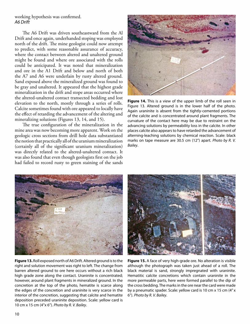
The A6 Drift was driven southeastward from the Al Drift and once again, underhanded stoping was employed north of the drift. The mine geologist could now attempt to predict, with some reasonable assurance of accuracy, where the contact between altered and unaltered ground might be found and where ore associated with the rolls could be anticipated. It was noted that mineralization and ore in the A1 Drift and below and north of both the A7 and A6 were underlain by rusty altered ground. Sand exposed above the mineralized ground was found to be gray and unaltered. It appeared that the highest grade mineralization in the drift and stope areas occurred where the altered-unaltered contact transected bedding and lost elevation to the north, mostly through a series of rolls. Calcite sometimes found with ore appeared to locally have the effect of retarding the advancement of the altering and mineralizing solutions (Figures 13, 14, and 15).
The true configuration of the mineralization in the mine area was now becoming more apparent. Work on the geologic cross sections from drill hole data substantiated the notion that practically all of the uranium mineralization (certainly all of the significant uranium mineralization) was directly related to the altered-unaltered contact. It was also found that even though geologists first on the job had failed to record rusty to green staining of the sands
Figure 13. Roll exposed north of A6 Drift. Altered ground is to the right and solution movement was right to left. The change from barren altered ground to ore here occurs without a rich black high grade zone along the contact. Uraninite is concentrated; however, around plant fragments in mineralized ground. In the concretion at the top of the photo, hematite is scarce along the edges of the concretion and uraninite is very scarce in the interior of the concretion, suggesting that calcite and hematite deposition preceded uraninite deposition. Scale: yellow card is 10 cm x 15 cm (4”x 6”). Photo by R. V. Bailey.
Figure 14. This is a view of the upper limb of the roll seen in Figure 13. Altered ground is in the lower half of the photo. Again uraninite is absent from the tightly-cemented portions of the calcite and is concentrated around plant fragments. The curvature of the contact here may be due to restraint on the advancing solutions by permeability loss in the calcite. In other places calcite also appears to have retarded the advancement of alterning-leaching solutions by chemical reaction. Scale: black marks on tape measure are 30.5 cm (12”) apart. Photo by R. V. Bailey.
Figure 15. A face of very high-grade ore. No alteration is visible although the photograph was taken just ahead of a roll. The black material is sand, strongly impregnated with uraninite. Hematitic calcite concretions which contain uraninite in the more permeable parts, here were formed parallel to the dip of the cross bedding. The marks in the ore near the card were made by a pneumatic spader. Scale: yellow card is 10 cm x 15 cm (4” x 6”). Photo by R. V. Bailey.
11
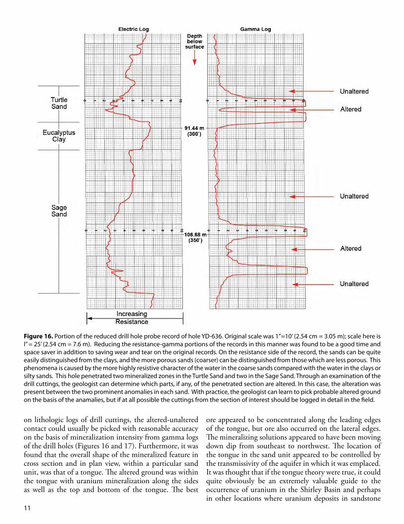
on lithologic logs of drill cuttings, the altered-unaltered contact could usually be picked with reasonable accuracy on the basis of mineralization intensity from gamma logs of the drill holes (Figures 16 and 17). Furthermore, it was found that the overall shape of the mineralized feature in cross section and in plan view, within a particular sand unit, was that of a tongue. The altered ground was within the tongue with uranium mineralization along the sides as well as the top and bottom of the tongue. The best
ore appeared to be concentrated along the leading edges of the tongue, but ore also occurred on the lateral edges. The mineralizing solutions appeared to have been moving down dip from southeast to northwest. The location of the tongue in the sand unit appeared to be controlled by the transmissivity of the aquifer in which it was emplaced. It was thought that if the tongue theory were true, it could quite obviously be an extremely valuable guide to the occurrence of uranium in the Shirley Basin and perhaps in other locations where uranium deposits in sandstone
Figure 16. Portion of the reduced drill hole probe record of hole YD-636. Original scale was 1”=10’ (2.54 cm = 3.05 m); scale here is I” = 25’ (2.54 cm = 7.6 m). Reducing the resistance-gamma portions of the records in this manner was found to be a good time and space saver in addition to saving wear and tear on the original records. On the resistance side of the record, the sands can be quite easily distinguished from the clays, and the more porous sands (coarser) can be distinguished from those which are less porous. This phenomena is caused by the more highly resistive character of the water in the coarse sands compared with the water in the clays or silty sands. This hole penetrated two mineralized zones in the Turtle Sand and two in the Sage Sand. Through an examination of the drill cuttings, the geologist can determine which parts, if any, of the penetrated section are altered. In this case, the alteration was present between the two prominent anomalies in each sand. With practice, the geologist can learn to pick probable altered ground on the basis of the anamalies, but if at all possible the cuttings from the section of interest should be logged in detail in the field.
12
existed. The first important test for this theory was to
determine if the alignment of several grid drill holes, which had encountered high-grade ore in the Turtle Sand, could be attributed to a tongue edge (later termed a roll front). An attempt to utilize this procedure was surprisingly successful. Not only did the high-grade holes fall into place along the leading edge of the tongue in the Turtle Sand, but also the occurrence of additional ore was very accurately predicted along the lateral edge of the tongue in an area where no ore had been encountered through grid drilling. Mining of this area will be discussed under the A420 through A428 stopes.
A7 Drift
As stoping northeast of the A6 Drift was being carried out, the A7 Drift advanced farther west to permit the extraction of more ore from the area north of the drift. Once again, as these additional stopes were opened, mineralization and ore were consistently found at the contact between altered and unaltered ground. No ore and practically no mineralization were found anywhere else. As now anticipated, all except the western most stopes were underlain by altered ground, with unaltered ground found above the mineralization.
Figure 18 (Page 14) illustrates two geologic cross
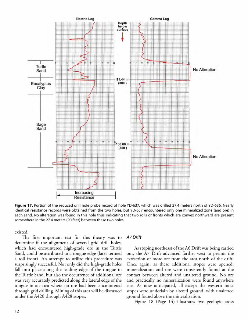
Figure 17. Portion of the reduced drill hole probe record of hole YD-637, which was drilled 27.4 meters north of YD-636. Nearly identical resistance records were obtained from the two holes, but YD-637 encountered only one mineralized zone (and ore) in each sand. No alteration was found in this hole thus indicating that two rolls or fronts which are convex northward are present somewhere in the 27.4 meters (90 feet) between these two holes.

13
Figure 18 (A). Location map for cross sections through A333 and A331.
A

B
Figure 18 (B). Cross sections through A333 and A331.
14

15
sections that were made and used in the course of mining both north and south of the A7 Drift. Drill holes are shown on the sections along with mineralization from drill hole probing. Uranium mineralization is shown in red with the shade of color indicative of grade. Calcite concretions are colored blue; calcite is very scarce except in concretions near the ore. Altered ground is shown as a rusty color and unaltered ground is colored gray. A stratigraphically lower geochemical front or roll that was not mined underground but is in the Sage Sand is shown in the lower part of the sections. A shallower roll that was mined north of the A7 Drift in A331 passes under the A7 Drift and is exposed again south of the A7 Drift in the A333 section. Notice that the deep and shallow rolls are concave in opposite directions. East of these sections, the altered ground to which each of these rolls is related, is continuous.
As the A7 Drift progressed west, the altered-unaltered contact that occurred near the back for several hundred feet was found to lose elevation and finally disappear through the bottom of the drift. Thus, on the west end the A1 Drift was driven entirely in unaltered ground.
Additional raises were now planned to permit the extraction of ore, which had been discovered by holes drilled early in the grid program, penetrating the Turtle Sand. The raises were planned in an area not yet opened by any other mining, but in an area where roll locations had been predicted and plotted on maps by the mine geologist. Here was the first real underground test of the roll front hypothesis and whether it could be successfully used in the prediction of uranium ore locations for underground mining purposes.
A420 Through A428 Stopes
The A201 Raise was the first one driven and was from the A10 Drift (a short stub from the A7 Drift). Excavation of the raise passed through about 3.5 meters (12 feet) of Eucalyptus Clay. After encountering a great deal of perched water, the raise penetrated the Turtle Sand (gravel at this location) where moderate grade (0.30 to about 0.60%) uranium mineralization was found. As anticipated by the geologist, no alteration was found at the raise location. The mine geologist’s maps had shown a high grade roll front in the Turtle Sand about 15 meters (50 feet) south of the raise, with no alteration between the raise and the roll. A cross-cut driven south from the raise proved the prediction to be accurate within about 3 meters (10 feet). A pre-mining map, post-mining map, and cross section of the A201 area are shown in figures 19, 20, and 21. The roll, the altered ground, and the ore were all found to have a relationship as had been predicted. The roll front theory was working well. Mine manager Mack Tilley was very happy to have accurate and dependable
ore predictions. On more than one occasion, the mine geologist pointed out where there was ore above or below scrams driven for ore production.
Stoping along the Turtle Sand roll in the A420 through the A428 stopes was carried out entirely along the roll. Practically no ore was found on the upper or lower limbs, which of course existed above or below altered ground. Almost all of the ore bottomed on the Eucalyptus Clay, an impermeable solution barrier.
The geologist could now re-evaluate some of the earlier data from drilling and mapping and incorporate this additional information in new predictions of mineralization, roll, and ore occurrences. In addition, it now appeared that this approach would have extremely important implications for future drilling plans, including drill hole spacing. All previous drilling had been carried out on a grid basis, but if the ore occurred along definable rolls associated principally with the edge of alteration, it was entirely possible that with accurate roll location prediction, drilling could be done on closely spaced ‘fences’ perpendicular to the roll trend to yield details of ore thickness, width, and grade.
The edge of the tongue, along which most of the ore occurred, was understandably found to be quite sinuous in the Turtle Sand. While existing grid drilling was seen as adequate in some areas, it appeared to be inadequate in others. The mine manager needed accurate identification of areas containing ore grade and thickness mineralization. In the areas where the geologist felt more control was desirable, fence drilling was recommended and carried out.
South of A7 Drift
Stoping north of the A7 Drift had revealed that the major subsidiary roll there turned south from a westerly trend and apparently passed under the A7 Drift (Figure 18). The term subsidiary roll was coined to describe roll features that were not major or terminal rolls. Early grid drilling in the area south of the A7 Drift had revealed the existence of moderate grade but quite thick ore in that area, up to 6 meters (20 feet).
Underhanded stoping was again used south of the A7 Drift where the geologist had once again plotted a roll and associated ore before stoping began. Drilling other than grid was not recommended in this area because of the apparent roll continuity and rather widespread character of the ore. As the stopes were opened, this prediction was found to be true and it was assumed that the major roll in this area was the same one that had been followed north of the A7 Drift. One important feature that differed markedly from the area north of the drift was that here the major roll was not a subsidiary roll as had been the case to the north. South of the drift, in the area west of

16
Figure 19. Pre-mining geological map of Turtle Sand in A201 Raise area. Possible roll location was indicated, along with possible edges of ore. Grid drilling was on both 50 and 100 foot centers. Note: two mineralized zones south of roll, one zone north of roll.
the A331, no altered ground existed below the horizon which was mined, indicating that the roll that had been a subsidiary roll north of the drift had become a major roll as shown in Figure 18.
Mapping and cross section work now indicated that the elevation of the apex of a roll could be a very valuable guide in differentiating between rolls or in efforts to determine roll location and trend. The rolls had a very strong tendency to maintain a constant elevation, and experience showed that a roll at elevation 2,067 meters (6,780 feet) could be expected to maintain essentially the same elevation and was not to be confused with one at 2,055 meters (6,740 feet), several tens of meters (a few
hundred feet) away. South of the A7, as in other stopes, photographs were
taken to illustrate the appearance of the ore, altered ground, calcite within the ore, and to illustrate the relationship between altered and unaltered ground (Figures 22 – 28). Water continued to be a problem throughout most of the mine (Figure 29). Some of the stopes, both north and south of the 7, were actually opened in ground, which was below the cone of depression created by water wells located near the shaft. This created disagreeable but not necessarily dangerous working conditions, and many of the stopes had to be constantly pumped. Pumping itself was difficult because the pumps were frequently being

17
Figure 20. Map of A201 Raise area after completion of stoping. Roll and edges of ore were found to be nearly where anticipated.
Figure 21. Cross section through A201 Raise along line A-A’.

18
Figure 22. Major Turtle Sand roll in A428. Altered ground is on the left contains sufficient uraninite so that it is ore grade within 61 cm of the roll. A bluish-gray band is visible paralleling the roll curvature next to the black high-grade ore. This coloration may be due to selenium concentration at the roll. Once again the curvature of the roll freely crosses the cross bedding even though here the host rock is of sand and gravel. Photo by R. V. Bailey.
Figure 23. Sage Sand roll south of A7 Drift. This face underground presented an unusual opportunity for the geologist-photographer because an excellent roll was exposed and a large face (about 2.7 m (9’) high and 2.1 m (7’) wide) was standing open without timber to block the view. The roll here does not display the usual band of rich mineralization along the contact but nevertheless the gradation from barren altered ground on the left to ore on the right is quite sharp. Uraninite is concentrated around plant fragments in the cross bedding. A calcite concretion can be seen in the lower right corner near the pneumatic spader. There is an apparent displacement near the roll due to the sand on the right jutting about one foot toward the camera. Photo by R. V. Bailey.
Figure 24. Irregular contact on the lower limb of the Sage Sand roll. Altered ground is above the mineralization. The irregularity is due to restraint on the altering solutions by hematitic calcite and carbonaceous material. Note that the two largest projections into altered ground have a hematitic calcite ‘core.’ The black fingers into altered ground have a carbonaceous ‘core.’ This stope was below the water table and two feet of mud and water were in the bottom of the stope when this picture was taken. Photo by R. V. Bailey.
Figure 25. Black high-grade ore is here concentrated along the contact. Cross bedding which is invisible in the altered ground is easily recognized in the ore. Timbering and lagging very often prevented photographing interesting faces seen in the mine.Photo by R. V. Bailey.

19
Figure 26. A tube of altered ground surrounded by ore. The angle of the wide part of the tube parallels the dip of the cross bedding. This tube was found in an area of rather complex mineralization where several subsidiary rolls, as well as one major roll were present. The tube was closed on one end, and the other end was connected with the large body of altered ground in the Sage Sand. The calcite in the right-hand corner is shown in more detail in Figure 27 below. Photo by R. V. Bailey.
Figure 27. The calcite here has a shape of a roll itself. It dips with the cross bedding but to a lesser degree than the tube. The black mineralization in the lower right-hand corner is associated with altered ground below and to the right of this picture. Photo by R. V. Bailey.
Figure 28. A roll with distincly rusty altered ground on the right. The inclination of the roll with the cross bedding is strictly a local feature. The gray sand just above the altered ground is unaltered ground, which has fallen down from above. The cavity and timber in the upper left corner indicates that the set above the photo has been mined out. Photo by R. V. Bailey.
Figure 29. Clear water running down the A9 Drift (toward the camera) is joined by UO2- bearing water from a stope where high-grade ore is being mined. A considerable amount of uraninite, which mostly occurs as a sand grain coating is removed from the sand agitation in water in the course of mining. Surface settling ponds were used to recover much of the uranium pumped out in mine waters. Note: the blue pencil in the sand at confluence. Photo by R. V. Bailey.
20
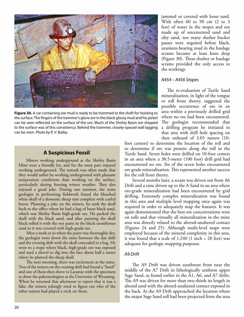
jammed or covered with loose sand. With often 60 to 90 cm (2 to 3 feet) of water in the stopes and ore made up of uncemented sand and silty sand, not many slusher bucket passes were required before black, uranium-bearing mud in the haulage scrams became at least knee deep (Figure 30). These slusher or haulage scrams provided the only access to the workings
A454 – A456 Stopes
The re-evaluation of Turtle Sand mineralization, in light of the tongue or roll front theory, suggested the possible occurrence of ore in an area within a previously drilled grid where no ore had been encountered. The geologist recommended that a drilling program be initiated in that area with drill hole spacing on then unheard of 3.05 meters (10-
foot centers) to determine the location of the roll and to determine if ore was present along the roll in the Turtle Sand. Seven holes were drilled on 10-foot centers in an area where a 30.5-meter (100 foot) drill grid had encountered no ore. Six of the seven holes encountered ore grade mineralization. This represented another success for the roll front theory.
Several months later, a scram was driven out from A6 Drift and a raise driven up to the A Sand in an area where ore-grade mineralization had been encountered by grid drilling. Extremely complex mineralization was found in this area and multiple level mapping once again was required in order to adequately map the features. It was again demonstrated that the best ore concentrations were on rolls and that virtually all mineralization in the mine area was directly related to the altered-unaltered contact (Figures 24 and 25). Although multi-level maps were employed because of the mineral complexity in this area, it was found that a scale of 1:240 (1 inch = 20 feet) was adequate for geologic mapping purposes.
A9 Drift
The A9 Drift was driven southwest from near the middle of the A7 Drift in lithologically uniform upper Sage Sand, as found earlier in the A1, A6, and A7 drifts. The A9 was driven for more than two-thirds its length in altered sand with the altered-unaltered contact exposed in the back. As the A9 Drift approached the location where the major Sage Sand roll had been projected from the area
Figure 30. A car containing ore mud is ready to be trammed to the shaft for hoisting to the surface. The fingers of the trammer’s glove are in the black glossy mud and his jacket can be seen reflected on the surface of the ore. Much of the Shirley Basin ore shipped to the surface was of this consistency. Behind the trammer, closely-spaced wall lagging can be seen. Photo by R. V. Bailey.
Miners working underground at the Shirley Basin Mine were a friendly lot, and for the most part enjoyed working underground. The remark was often made that they would rather be working underground with pleasant temperature conditions than working on the surface, particularly during freezing winter weather. They also enjoyed a good joke. During one summer, the mine geologist in performing fieldwork found the bleached white skull of a domestic sheep ram complete with curled horns. Planning a joke on the miners, he took the skull back to the office where he had a bag of loose black sand, which was Shirley Basin high-grade ore. He packed the skull with the black sand, and after painting the skull black rolled it with the wet paint in the black uraniferous sand so it was covered with high-grade ore.
After a week or so when the paint was thoroughly dry, the geologist went down the mine between the day shift and the evening shift with the skull concealed in a bag. He went to a stope where black, high-grade ore was exposed and used a shovel to dig into the face about half a meter where he planted the sheep skull.
The next morning, there was excitement at the mine. Two of the miners on the evening shift had found a “fossil” and one of them then drove to Laramie with the specimen to show the paleontologists at the University of Wyoming. When he returned that afternoon to report that it was a fake, the miners jokingly tried to figure out who of the other miners had played a trick on them.
A Suspicious Fossil

21
south of the A7 Drift, the altered-unaltered contact was found to lose elevation as expected, and disappeared in the bottom of the drift. The A9 Drift was then driven for the remainder of its length in unaltered coarse to silty sand.
It should be pointed out that in driving the drifts in the Shirley Basin Mine only a small amount of explosives were used. Indeed, sometimes only with great difficulty was serious back caving and face caving at the heading was prevented. The sand that did not cave or slough off could usually be easily dug with pneumatic spaders. Long-hole drilling ahead of the drift was employed in the later stages of mining. This was found to help a great deal in lowering water from high up in the face and back.
As the A9 Drift approached its southernmost point shown on the map (Figure 35), it emerged from under the Eucalyptus Clay (which had been scoured away) and encountered a great deal of perched water in the Turtle Sand. The drift was lost several times in this area and drifting finally was stopped because of the excessive water and back caving (Figures 26 – 28).
A448, A451, and A460 Stopes
The A448 Stope was driven northwest and north from the A9 Drift along the major Sage Sand roll, and the A451 stope was driven south from the A9 along the same roll; both were underhanded stopes. As a general rule in the Shirley Basin Mine, little ore was found on the limbs above and below altered ground, but in the A451, some good ore was found on the lower limb. The occurrence of this ore on the lower limb had been anticipated because it had been predicted on the mine geologist’s maps, but fence drilling was also recommended to define more adequately the roll location, ore width, thickness, and grade.
The roll trend itself in the A451 and the A460 to the south was very straight. In a distance of almost 150 meters (500 feet), the roll location varied less than 4.6 meters (15 feet) from a straight line (Figure 35). The elevation of the roll apex rose slightly to the south with practically no fluctuations. This alignment is testament to the uniform character of the host sand.
While the A9 Drift was being driven south, studies of drill hole data in the area ahead of it and for which mining was planned, indicated that mineralization in the area was quite complicated due primarily to complex sedimentary features such as scours and channel fills. It was recommended that additional grid drilling be carried out so the geological features could be better understood before any closer spaced drilling, if needed, could be considered.
A458 - A461 Scrams
Development scrams were driven from near the end of the A9 Drift and raises were driven up from the scrams to the Turtle Sand. This area was within that recognized as being extremely complex, but as previously noted, an attempt had been made by the geologist to pick roll locations from grid drilling information.
Complex mineralization was encountered in the A458 and A461 scrams in the Turtle Sand. Ore assumed to be ahead of a roll was found instead on the lower limb. Another roll was found where projected, but it had very little ore associated with it; clay interbeds within the Turtle Sand caused many complex but weak mineralization features and altered ground extended into an area where none had been projected. Nevertheless, the basic mineralization concepts of the roll fronts were found to hold true (Figures 33 – 37).
In the A458 scram, the best ore encountered by a grid drill hole was found on the lower limb rather than just ahead of a roll, but the stoping there (albeit limited) revealed the presence of a possible major roll. The ore on the lower limb was actually in the upper Sage Sand and had migrated there from the Turtle Sand through a scour in the Eucalyptus Clay. The scour had been anticipated from resistance log interpretations. At about that point in time development work was stopped because of pending contract changes proposed by the U.S. Atomic
Figure 31. Part of roll A454 shaped like a reverse “3”. The host rock here is sand and gravel in the Turtle Sand. The projection of mineralization into altered ground at the center of the “3” was probably caused by a clayey and less permeable zone, which retarded the advancement of mineralization solutions, and which were moving from right to left. Scale: yellow card is 10 cm x 15 cm (4” x 6”). Photo by R. V. Bailey.
22
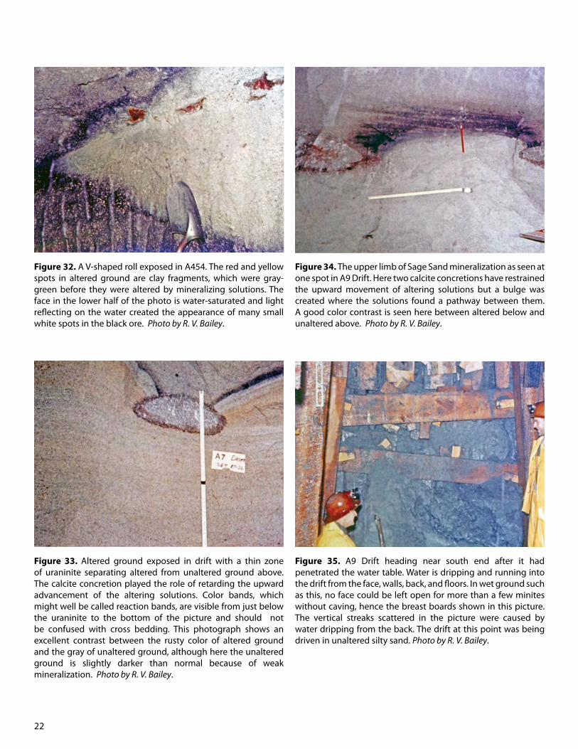
Figure 32. A V-shaped roll exposed in A454. The red and yellow spots in altered ground are clay fragments, which were gray-green before they were altered by mineralizing solutions. The face in the lower half of the photo is water-saturated and light reflecting on the water created the appearance of many small white spots in the black ore. Photo by R. V. Bailey.
Figure 33. Altered ground exposed in drift with a thin zone of uraninite separating altered from unaltered ground above. The calcite concretion played the role of retarding the upward advancement of the altering solutions. Color bands, which might well be called reaction bands, are visible from just below the uraninite to the bottom of the picture and should not be confused with cross bedding. This photograph shows an excellent contrast between the rusty color of altered ground and the gray of unaltered ground, although here the unaltered ground is slightly darker than normal because of weak mineralization. Photo by R. V. Bailey.
Figure 34. The upper limb of Sage Sand mineralization as seen at one spot in A9 Drift. Here two calcite concretions have restrained the upward movement of altering solutions but a bulge was created where the solutions found a pathway between them. A good color contrast is seen here between altered below and unaltered above. Photo by R. V. Bailey.
Figure 35. A9 Drift heading near south end after it had penetrated the water table. Water is dripping and running into the drift from the face, walls, back, and floors. In wet ground such as this, no face could be left open for more than a few minites without caving, hence the breast boards shown in this picture. The vertical streaks scattered in the picture were caused by water dripping from the back. The drift at this point was being driven in unaltered silty sand. Photo by R. V. Bailey.
23
Energy Commission, purchaser of uranium “yellow cake” concentrate.
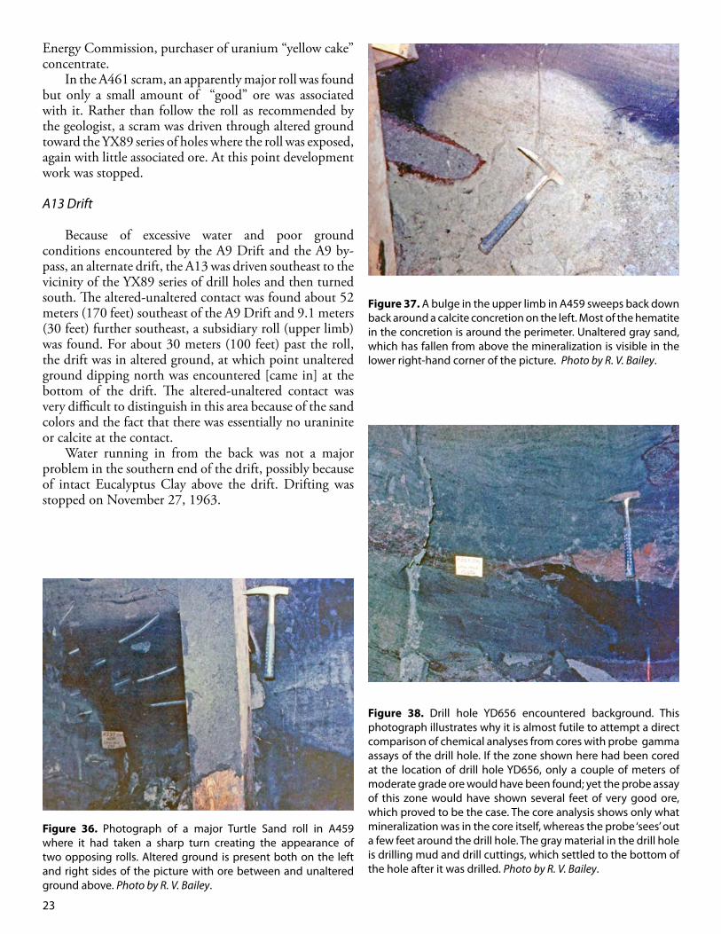
In the A461 scram, an apparently major roll was found but only a small amount of “good” ore was associated with it. Rather than follow the roll as recommended by the geologist, a scram was driven through altered ground toward the YX89 series of holes where the roll was exposed, again with little associated ore. At this point development work was stopped.
A13 Drift
Because of excessive water and poor ground conditions encountered by the A9 Drift and the A9 by-pass, an alternate drift, the A13 was driven southeast to the vicinity of the YX89 series of drill holes and then turned south. The altered-unaltered contact was found about 52 meters (170 feet) southeast of the A9 Drift and 9.1 meters (30 feet) further southeast, a subsidiary roll (upper limb) was found. For about 30 meters (100 feet) past the roll, the drift was in altered ground, at which point unaltered ground dipping north was encountered [came in] at the bottom of the drift. The altered-unaltered contact was very difficult to distinguish in this area because of the sand colors and the fact that there was essentially no uraninite or calcite at the contact.
Water running in from the back was not a major problem in the southern end of the drift, possibly because of intact Eucalyptus Clay above the drift. Drifting was stopped on November 27, 1963.
Figure 36. Photograph of a major Turtle Sand roll in A459 where it had taken a sharp turn creating the appearance of two opposing rolls. Altered ground is present both on the left and right sides of the picture with ore between and unaltered ground above. Photo by R. V. Bailey.
Figure 37. A bulge in the upper limb in A459 sweeps back down back around a calcite concretion on the left. Most of the hematite in the concretion is around the perimeter. Unaltered gray sand, which has fallen from above the mineralization is visible in the lower right-hand corner of the picture. Photo by R. V. Bailey.
Figure 38. Drill hole YD656 encountered background. This photograph illustrates why it is almost futile to attempt a direct comparison of chemical analyses from cores with probe gamma assays of the drill hole. If the zone shown here had been cored at the location of drill hole YD656, only a couple of meters of moderate grade ore would have been found; yet the probe assay of this zone would have shown several feet of very good ore, which proved to be the case. The core analysis shows only what mineralization was in the core itself, whereas the probe ‘sees’ out a few feet around the drill hole. The gray material in the drill hole is drilling mud and drill cuttings, which settled to the bottom of the hole after it was drilled. Photo by R. V. Bailey.
24
This concludes the description of individual areas in the mine.Major Observed Mineral Features
The accompanying illustration (Figure 41) was initially prepared in late–1963 to emphasize the more important mineral features observed in the mine. The presence or type of clay, pyrite, limonite, coalified wood, uraninite, calcite, hematite and color are compared as normally found in altered, mineralized, and unaltered ground. H2S gas has been noted in some cores of ore obtained northwest
of the mining operation. The direction of mineralizing solution movement appears to have been to the northwest but current groundwater movement appears to be to the south, in the same direction as the surface water in the Little Medicine Bow River. We do not know the pH of the mineralizing waters but assume it was about the same as it is currently, approximately 7.8 pH.
Recent Work Performed
Beginning in the summer of 2010, interpretive work was performed by geologists R. V. Bailey and Matt Cunningham, who reviewed and analyzed surviving records from exploration drilling done in the late 1950s and early 1960s. The purpose of the current presentation is to put the data in a modern electronic form, and to comprehensively map out the geochemical fronts both in cross-section and plan view. This work is important because historical mapping of the fronts has been shown on more than one map and the available historical maps do not cover all areas we had wished to include in this publication. In addition, few historical cross sections made when the mine was active are available because they have been lost or destroyed over time.
In the course of assembling and interpreting the data needed to present the Shirley Basin maps and cross sections, a database using Rockworks®, a Microsoft Access database software, was built with 417 drill holes with location and certain basic stratigraphic data entered. Records for a substantial number of holes that were drilled are not in this database mainly due to non-availability of the data. The exact number of records missing from the database is unknown but there were an adequate number available, as well as maps and cross sections prepared by Mr. Bailey when the mine was in operation. In addition, 409 geophysical gamma and resistivity logs were scanned as TIFF images, an electronic image format. The electric logs made of the Shirley Basin drill holes at the mine were created using a sort of “homemade” logging unit, which showed electrical resistivity and gamma radiation. Any gamma “reruns” (intervals of high radioactivity) had to be shown on a separate section of the paper printout and were run at various vertical scales depending on what was needed for a particular drill hole. Metric scales were not being used and a radioactive interval might first be logged at a scale of one inch = 10 feet and then reclogged at a vertical scale of one inch = 5 feet in order to show more detail. The multi-scaled logs, however, are difficult to compare side by side. Nearly two-thirds of the drill holes in the database have at least one associated scanned log. In addition to the electronic data, paper photocopies of the sample description logs (sample descriptions prepared by the geologists) were made for approximately 250 of the holes. Some of the drill holes may not have had original
Figure 39. Example of a very good ore face in a very wet stope in A358. Shot holes have been drilled and are being loaded for blasting. The working face was shiny with water and the vertical streaks in the center of the picture were caused by water running into the stope from the back. Photo by R. V. Bailey.
Figure 40. Example of a very well-formed roll with associated black high-grade ore. A band of blue-gray mineralization (possibly selenium-rich) parallels the roll curvature. Photo by R. V. Bailey.

Figure 41. Major observed mineral features in Shirley Basin uranium deposits (hypothetical cross section). 25
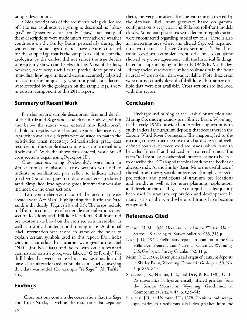
26
sample descriptions. Color descriptions of the sediments being drilled are
of little use as almost everything is described as “blue-gray” or “green-gray” or simply “gray,” but many of these descriptions were made under very adverse weather conditions on the Shirley Basin, particularly during the wintertime. Some logs did not have depths corrected for the sample lag; that is the samples as laid out for the geologists by the drillers did not reflect the true depths subsequently shown on the electric log. Most of the logs, however, were very useful with precise descriptions of individual lithologic units and depths accurately adjusted to account for sample lag. Uranium grade calculations were recorded by the geologists on the sample logs, a very important component to this 2011 report.
Summary of Recent Work
For this report, sample description data and depths of the Turtle and Sage sands and clay units above, within and below the sands, were entered into Rockworks®. Lithologic depths were checked against the resistivity logs (when available); depths were adjusted to match the resistivities when necessary. Mineralization grade data recorded on the sample descriptions was also entered into Rockworks®. With the above data entered, work on 23 cross sections began using Rockplot 2D. Cross sections, using Rockworks®, were built in similar format to historical cross sections with red to indicate mineralization, pale yellow to indicate altered (oxidized) sand and gray to indicate unaltered (reduced) sand. Simplified lithology and grade information was also included on the cross sections.
Two comprehensive maps of the area map were created with Arc Map®, highlighting the Turtle and Sage sands individually (Figures 20 and 21). The maps include roll front locations, area of ore grade mineralization, cross section locations, and drill hole locations. Roll front and ore locations are based on the cross sections assembled, as well as historical underground mining maps. Additional label information was added to some of the holes to explain certain symbols used in this report. Drill holes with no data other than location were given a the label “ND” (for No Data) and holes with only a scanned gamma and resistivity log were labeled “G & R only.” For drill holes that were not used in cross sections but did have clear alteration/reduction data, a label conveying that data was added (for example “re Sage,” “Alt Turtle,” etc.).
Findings
Cross sections confirm the observation that the Sage and Turtle Sands, as well as the mudstone that separate
them, are very consistent for the entire area covered by the database. Roll front geometry based on gamma configuration is very clear and followed roll-front models closely. Some complications with determining alteration were encountered regarding subsidiary rolls. There is also an interesting area where the altered Sage cell separates into two distinct cells (see Cross Section I-I’). Final roll front locations assembled from drill hole data alone showed very close agreement with the historical findings, based on stope mapping in the early 1960s by Mr. Bailey. Discrepancies were mostly limited to sinuosity in the front in areas where no drill data was available. Note these areas were not necessarily devoid of drill holes, but rather drill hole data were not available. Cross sections are included with this report.
Conclusion
Underground mining at the Utah Construction and Mining Co. underground site in Shirley Basin, Wyoming, in the early 1960s provided an excellent opportunity to study in detail the uranium deposits that occur there in the Eocene Wind River Formation. The mapping led to the exciting concept that the ore existed at discreet and well-defined contacts between oxidized sands, which came to be called “altered” and reduced or “unaltered” sands. The term “roll front” or geochemical interface came to be used to describe the “C” shaped terminal ends of the bodies of altered sands. At the Shirley Basin Mine the usefulness of the roll front theory was demonstrated through successful projections and predictions of uranium ore locations and trends, as well as for mine planning, exploration, and development drilling. The concept has subsequently been used in uranium exploration and development in many parts of the world where roll fronts have become recognized.
References Cited
Denson, N. M., 1959, Uranium in coal in the Western United States: U.S. Geological Survey Bulletin 1055, 315 p.
Love, J. D., 1954, Preliminary report on uranium in the Gas Hills area, Fremont and Natrona Counties, Wyoming: U.S. Geological Survey Circular 352, 11 p.
Melin, R. E., 1964, Description and origin of uranium deposits in Shirley Basin, Wyoming: Economic Geology, v. 59, No. 5, p. 835–849.
Stuckless, J. R., Nkomo, I. T., and Doe, B. R., 1981, U-Th-Pb systematics in hydrothermally altered granites from the Granite Mountains, Wyoming: Geochimica et Cosmochimica Acta, v. 45, p. 635–645.
Stuckless, J.R., and Nkomo, I.T., 1978, Uranium-lead isotope systematics in uraniferous alkali-rich granites from the
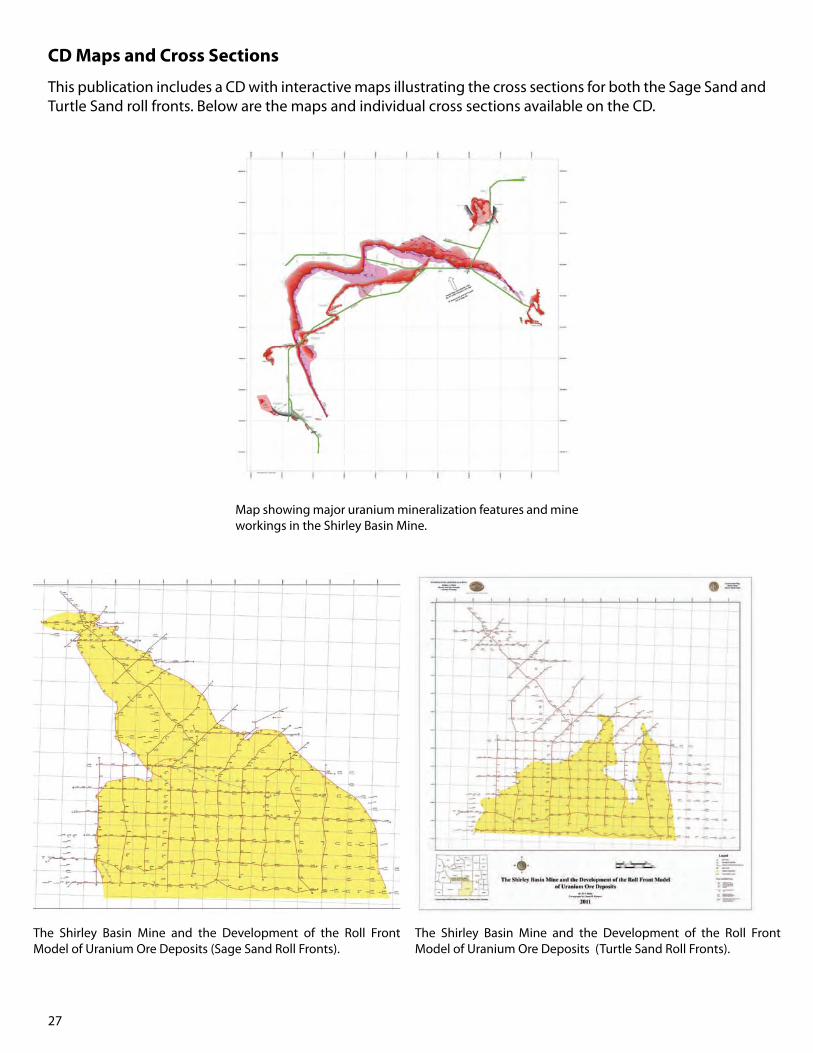
27
Map showing major uranium mineralization features and mine workings in the Shirley Basin Mine.
The Shirley Basin Mine and the Development of the Roll Front Model of Uranium Ore Deposits (Sage Sand Roll Fronts).
The Shirley Basin Mine and the Development of the Roll Front Model of Uranium Ore Deposits (Turtle Sand Roll Fronts).
This publication includes a CD with interactive maps illustrating the cross sections for both the Sage Sand and Turtle Sand roll fronts. Below are the maps and individual cross sections available on the CD.
CD Maps and Cross Sections
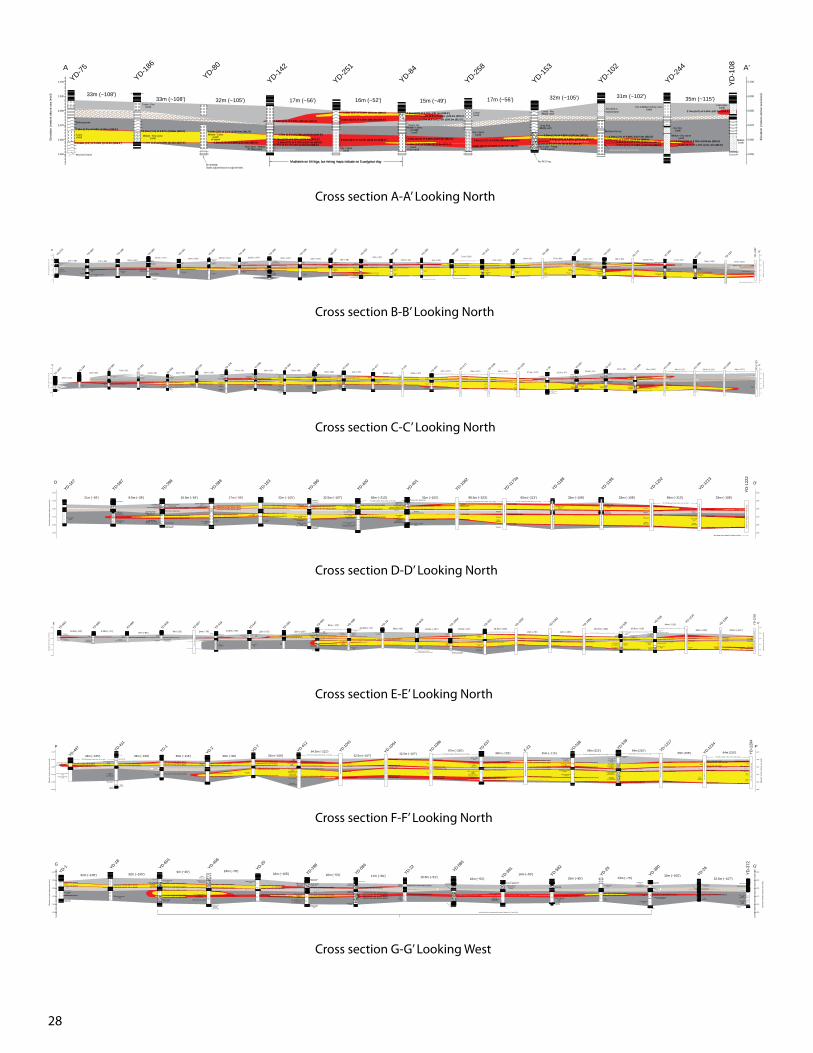
28
Cross section A-A’ Looking North
2,050
2,060
2,070
2,080
2,090
2,100
Ele
vatio
n (m
eter
s ab
ove
sea
leve
l)
2,050
2,060
2,070
2,080
2,090
2,100
Ele
vatio
n (m
eter
s ab
ove
sea
leve
l)
Medium grained
Coarse(sand)
Mud and Sand
Described as mud and sand
Gray to Tan. Medium - Coarse
& Pebbly(sand)
33m (~108')33m (~108') 32m (~105') 17m (~56') 16m (~52') 15m (~49') 17m (~56') 32m (~105') 31m (~102') 35m (~115')
No resistivity. Depths adjusted based on adjacent holes.
No RES log.
Mudstone from res
Multi-peaked high gamma base
Thick, double peaked, high gamma base
Double-peaked base
A A'
Mudstone on lith logs, but mining maps indicate no Eucalyptus clay
YD-75YD-18
6
YD-80
YD-142
YD-251
YD-84
YD-258
YD-153
YD-102
YD-244
YD
-108
0.30m (1.0') of 0.03% @103m (338.0')
0.46m (1.5') of 0.34% @112.5m (369.0')
0.46m (1.5') of 0.27% @104m (340.5')
0.30m (1.0') of 0.29% @112m (367.0')
0.30m (1.0') of 0.1% @104.0m (341.0')
0.30m (1.0') of 0.94% @111.6m (366.0')
0.30m (1.0') of 0.74% @105.9m (347.5')
1.52m (5.0') of 0.72% @110.7m (363.0')1.37m (4.5') of 0.11% @112.2m (368.0')
0.46m (1.5') of 0.49% @91.0m (298.5')
8.54m (28.0') of 0.16% @106.1m (348.0')
0.61m (2.0') of 0.10% @91.3m (299.5')0.91m (3.0') of 2.61% @93.0m (305.0')
1.37m (4.5') of 2.73% @95.3m (312.5')
4.73m (15.5') of 0.20% @107.0m (351.0')
0.46m (1.5') of 0.18% @112.8m (370.0')3.51m (11.5') of 0.19% @106.9m (350.5')
3.66m (12.0') of 0.02% @110.4m (362.0')
0.30m (1.0') of 0.82% @106.9m (350.5')
1.07m (3.5') of 0.1% @112.0m (367.5')
0.30m (1.0') of 0.68% @107.5m (352.5')
0.61m (2.0') of 3.71% @110.7m (363.0')1.37m (4.5') of 3.49% @112.2m (368.0')
0.76m (2.5') of 0.76% @109.6m (359.5')2.44m (8.0') of 1.11% @111.4m (365.5')
2.74m (9.0') of 0.06% @87.8m (288.0')
1.52m (5.0') of 0.05% @96.0m (315.0') 5.64m (18.5') of 0.24% @93.4m (306.5')
1.07m (3.5') of 4.59% @109.1m (358.0') 0.30m (1.0') of 0.10% @109.5m (359.0')0.76m (2.5') of 0.15% @109.0m (357.5')
Coarse - Fine(sand)
Medium - Very coarse(sand)
Medium - Coarse(sand)
@ bottom
Coarse(sand)
Coarse( Clean sand)Fine- Coarse
(sand)
Fine- Coarse(sand)
Very Coarse - Medium & Pebbly (sand)
Coarse - Fine(Muddy sand)
Gray, Fine(Muddy sand) Very Fine
(sand)
Coarse:lean(sand)
Medium - Very coarse(sand)
Fine to Medium to Very coarse(sand)
Medium (sand)
Very Coarse - Pebbly(sand & gravel)
Very coarse - Medium(sand)
Medium-Coarse(sand)
Fine - G(sand)
Size increase w/ depth
Fine - Coarse(sand)
carb, pyrt
Sandy Silt
Coarse - Pebbly(sand & gravel)
sm carb, sm pyrt
Fine(sand)
Medium(sand)
Fine - Very coarse(sand)
Medium - Very coarse(sand)
Fine grading to Coarse and clean
(sand)
Mudstone (described as silt)
Coarse - G(sand & gravel)
abt pyrt, sm carb, U coating
Medium - Very coarse(sand)
local pyrt and carb
Pebbls and Very coarse(sand & gravel)
sand local yellow
Fine (sand)
Sand describedas mud
Fine - Coarse(sand)
Fine - Coarse(sand)
Medium - Coarse(sand)
Medium - Coarse(sand)
Tr carbon
Fine - Medium(sand)
Medium - Very coarse(sand)
Sand (described as sand and silt)
Medium - Very coarse(sand)
Sand, Clay & Silt (50-25-25%)
Much coarser than above interval
(sand)Muddy sand
Medium - Gran. Very coarse(sand)
Fine-MediumReddish staining
(sand)
Medium -Pebbly (VC-Gran)(sand & gravel)
pebbls at base, pyr, sm carb
Trace
Depths adjusted based on gammaDepths adjusted based on gamma
Trace
Mudstone (described as sand and silt)
Fine(sand)
Coarse(sand)
Data not avaliable for holes to East.
Mudstone grading into sand
Silt and Very fine - fine sand w/ clay mtxMedium - Very coarse
(sand)
Silt w/ clay mtx
Fine -Very coarse(sand)
Sandy silt
Fine - Very coarse(sand)
Very fine - Medium(silt)
Silt grading to medium sand
Very fine - Medium silt Gary to Gray-White
Fine - Coarse (MED) (sand) Minor Wht, Pnk & Orng Cal.
Fine - Gran. (M-VC) (sand)Gray except locally bleached white.
Gray to Gray-Green(Mudstone)
Medium - Coarse - Fine(sand)
Fine - Pebbly (VC)(sand)
Fine - Pebbly (C-VC)(sand)
Mudstone (very silty)
Abt pyriteGravelly toward bottom. Sand gray w/ tan cast
97m (~318')
33.5m (~110') 32.5m (~107') 32m (~105') 33m (~108') 18m (~59')~15m (~49')
13.5m (~44') 12m (~39')
71m (~233')
21m (~69')19m (~62') 27m (~89') 16m (~52') 19m (~62') 12.5m (~41') 17m (~56')
33m (~108')17m (~56') 17m (~56') 32m (~105') 32.5m (~107') 33m (~108')
YD-190 between these holes, but no good data
2,050
2,060
2,070
2,080
2,090
2,100
Ele
vatio
n (m
eter
s ab
ove
sea
leve
l)
B
Alteration indicated by holes North and south of Section
Trace min
1.22m (4.0') of 0.15% @91.6m (300.5')
0.46m (1.5') of 0.40% @98.5m (323.0')
0.15m (0.5') of 4.42% @102.0m (334.5')
1.52m (5.0') of 0.20% @90.9m (298.0')
0.76m (2.5') of 0.30% @ 97.6m (320.0')
0.61m (2.0') of 3.39% @101.4m (332.5')
1.22m (4.0') of 0.51% @89.6m (294.0')
0.76m (2.5') of 0.50% @97.0m (318.0')
0.46m (1.5') of 4.55% @103.7m (340.0')
2.90m (9.5') of 0.90% @88.9m (291.5')
0.61m (2.0') of 0.20% @96.3m (316.0')
0.30m (1.0') of 1.09% @111.4m (365.5')
1.98m (6.5') of 2.71% @89.2m (292.5')
0.61m (2.0') of 0.03% @95.7m (314.0')
3.66m (12.0') of 0.03% @104.9m (344.0')
2.13m (7.0') of 1.67% @89.3m (293.0')
0.30m (1.0') of 0.35% @96.2m (315.5')
0.30m (1.0') of 0.62% @112.0m (367.5')
2.13m (7.0') of 2.03% @88.4m (290.0')
0.30m (1.0') of 0.12% @96.0m (315.0')
0.46m (1.5') of 0.03% @111.4m (365.5')
0.30m (1.0') of 0.10% @87.8m (288.0')0.30m (1.0') of 0.25% @90.5m (297.0')
0.61m (2.0') of 0.05% @95.3m (312.5')
0.46m (1.5') of 0.05% @111.7m (366.5')
0.46m (1.5') of 0.28% @85.7m (281.0')
0.30m (1.0') of 0.07% @90.2m (296.0')
0.30m (1.0') of 0.13% @95.0m (311.5')
0.30m (1.0') of 0.05% @110.5m (362.5')
0.61m (2.0') of 0.02% @89.9m (295.0')
1.22m (4.0') of 0.01% @93.6m (307.0')
0.46m (1.5') of 0.04% @111.0m (364.0')
0.30m (1.0') of 0.38% @88.3m (289.5')0.76m (2.5') of 0.04% @88.6m (290.5')0.30m (1.0') 0.06% @90.5m (297.0')
0.46m (1.5') of 0.24% @93.3m (306.0')
0.30m (1.0') of 0.31% @98.3m (322.5')
0.30m (1.0') of 0.15% @92.7m (304.0')
4.27m (14.0') of 0.16% @98.2m (322.0')
1.68m (5.5') of 0.04% @102.4m (336.0')
0.30m (1.0') of 0.07% @110.4m (362.0')
3.51m (11.5') of 0.06% @87.0m (285.5')
1.52m (5.0') of 0.04% @101.8m (334.0')
0.30m (1.0') of 0.75% @112.8m (370.0')
0.30m (1.0') of 0.37% @103.2m (338.5')061m (2.0') of 1.25% @1049.m (344.0')
0.23m (0.75') of 1.83% @113.5m (372.3')
1.22m (4.0') of 0.06% @110.1m (361.0') 0.46m (1.5') of 0.37% @109.9m (360.5')
2.13m (7.0') of 0.05% @102.1m (335.0') 2.44m (8.0') of 0.27% @100.9m (331.0') 2.74m (9.0') of 0.38% @100.3m (329.0')0.46m (1.5') of 0.48% @98.3m (322.5')
0.91m (3.0') of 0.29% @101.5m (333.0')
1.37m (4.5') of 0.04% @97.6m (320.0')
YD-373
YD-380
YD-168
YD-550
YD-196
YD-305
YD-164
YD-350
YD-161
YD-197
YD-302
YD-194
YD-283
YD-198
YD-213
YD-274
YD-188
YD-182
YD-333
YD-174
YD-363
YD-160
YD-216
YD
-128
7
2,050
2,060
2,070
2,080
2,090
2,100
B'
Ele
vatio
n (m
eter
s ab
ove
sea
leve
l)
No
sam
ple
desc
riptio
n.Li
th. a
nd m
in. b
ased
on
Res
and
Gam
ma.
No
sam
ple
desc
riptio
n. G
rade
s no
t ava
ilabl
eLi
th. a
nd m
in. b
ased
on
Res
and
Gam
ma.
adju
sted
to m
atch
adj
acen
t hol
es.
Base
d on
sca
nned
log.
Hol
e el
evat
ion
appe
ars
to b
e 15
' off,
No s
ampl
e de
scrip
tion.
Lith
. and
min
. bas
ed o
n Re
s an
d G
amm
a.
Mudstone (described as Silt) Mudstone (described as Silt)
Coarse(sand)
Fine - Coarse(sand)
Fine(sand)
Very Coarse(sand)
Very fine - Medium(sand)
Very coarse - MediumPebbles
(sand & gravel)
Fine(sand)
Coarse(sand)
Sand
Mudstone
Fine(sand)
Fine-Medium( muddy sand)
Very Coarse - Pebbly(sand & gravel)
Fine - Very Coarse becoming Very fine - Medium(sand)
Medium - Very coarse & Pebbly
(sand)
Fine - Medium(sand)
Silt and Very fine sand w/ clay mtx
Poo
r Sam
ple
Des
crip
tions
Cross section B-B’ Looking North
Silt becoming Fine - Medium sand
Medium - Pebbly, Granule(sand &gravel)
Very fine - (Medium)Local Tan w/ strong rusty stn
1.52m (5.0') of 0.04% @87.2m (286.0')
0.46m (1.5') of 0.05% @92.1m (302.0')
0.61m (2.0') of 0.01% @104.9m (344.0')
0.61m (2.0') of 0.05% @103.4m (339.0')0.61m (2.0') of 0.01% @104.9m (344.0')
Sand: Fine - Very coarse(sand)
Gray, Ark. Abt pyrminor carb trash
Mudstone(described as silt)
Silty, Very fine - Medium(sand)
Tan to Lt GrayMedium - Granules
(sand & gravel)Very abt Fine - Pebbly Pyrt
Very fine - Coarse(sand)
Minor carb trashMinor pyr
Mudstone(described as silt)
0.46m (1.5') of 0.05% @87.0m (285.5')
0.30m (1.0') of 0.07% @90.9m (298.0')
0.30m (1.0') of 0.06% @96.3m (316.0')
0.91m (3.0') of 0.08% @101.8m (334.0')
2.44m (8.0') of 0.02% @85.4m (280.0')
0.46m (1.5') of 0.07% @92.1m (302.0')
1.22m (4.0') of 0.08% @102.7m (337.0')
Mudstone
SandFine - Coarse
(sand)Pyr. Carb
0.61m (2.0') of 0.33% @87.8m (288.0')
0.30m (1.0') of 0.11% @91.6m (300.5')
0.46m (1.5') of 0.05% @102.9m (337.5')
Fine - Medium(sand)
Minor yel stn.
Medium - Coarse(sand)
Coarse -Very coarse (sand)
Much coarser than aboveBleached flds.
0.30m (1.0') of 0.16% @88.3m (289.5')
0.61m (2.0') of 0.06% @91.8m (301.0')
1.98m (6.5') of 0.14% @105.6m (346.5')
Mudstone(described as muddy sand)
Mudstone(described as muddy sand)
Coarse(sand)
Mudstone(described as muddy sand)
1.37m (4.5') of 0.14% @90.4m (296.5')
0.30m (1.0') of 0.09% @97.3m (319.0')
0.46m (1.5') of 0.36% @112.3m (368.5')
Silty sand w/ clat mtxGray-Green
Medium - Pebbly (VC)(sand &gravel)Gray becoming
Gray-Tan
Very fine - Medium (F)BleachedFine - (Medium
(sand)). Very fine - (Medium)
(silty sand)Tan to rustyCoarse -Pebbly
(sand & gravel)Mostly Gray-Tan w/ rusty stn (alt)
0.76m (2.5') of 0.08% @89.6m (294.0')0.91m (3.0') of 0.27% @90.4m (296.5')
2.29m (7.5') of 0.44% @100.0m (328.0')
0.30m (1.0') of 0.02% @110.7m (363.0')0.46m (1.5') of 0.02% @112.3m (368.5')
Fine - Very coarseVery abt pyr
Medium - granule(sand & gravel)
abt pyr
Silty to Fine(mudstone)
Fine - MediumCoarser w/depth
(sand)v abt pyr
1.68m (5.5') of 0.26% @88.9m (291.5')
0.76m (2.5') of 0.19% @101.4m (332.5')
0.30m (1.0') of 0.14% @114.0m (374.0')
Very fine - (Medium(sand)
Medium - Gran (VC)(sand)
Gry to Lt Tan, Abt Pyr
Very fine - Coarse (M)(sand)
Very Lt Gray to White
Medium - Pebbly (Gran)(sand & gravel)Some rusty stn Some pyr top
1.22m (4.0') of 0.02% @86.0m (282.0')1.83m (6.0') of 0.03% @87.8m (288.0')0.30m (1.0') of 0.51% @89.6m (294.0')0.61m (2.0') of 0.75% @91.5m (300.0')
0.30m (1.0') of 0.18% @ 103.0m (338.0')1.07m (3.5') of 0.02% @103.4m (339.0')0.91m (3.0') of 0.14% @104.4m (342.5')
4.42m (14.5') of 0.05% @105.3m (345.5') (Between tails)
0.30m (1.0') of 0.29% @115.4m (378.5')
Abt carb trash & clay111-115m (365-78').
No mineral notedMudstone
Sand
Mudstone
Fine or Silty Sand
Coarseclean Sand
Mudstone
Sand(described as muddy sand)
Mudstone (described as sand (sample lag))
white to gray topto whitt - pink - rust -
gray bottom
Sand
Mudstone
Fine(sand)
Coarse (sand)
Mudstone
1.07m (3.5') of 0.15% @109.8m (360.0')
0.30m (1.0')of 0.08% 97.9m (321.0')
Lt gray w/ abt sand(muddy sand)
Lt gray(mudstone)
Fine - Coarse(sand)
1.98m (6.5') of 0.12% @100.2m (328.5')
Medium - Very coarse (VC)(sand)
Very fine - Coarse (M)(sand)
silty
Fine - Coarse(sand)
3.05m (10.0') of 0.29% @100.6m (330.0')0.91m (3.0') of 0.07% @103.7m (340.0')
Fine - Medium( muddy sand)
Medium - Gran (VC)(sand & gravel)
Medium - Very coarse (Crs)(sand)
4.27m (14.0') of 0.16% @99.5m (326.5')
Silt w/ clay mtx
Medium - Gran (VC)(sand)
Gravelly
Fine - M (F)(sand)
Fine - Coarse (M)(sand)
Fine - Very coarse (C)(sand)
Clayey(sand & silt)
0.61m (2.0') of 0.34% @99.8m (327.5')
0.91m (3.0') of 0.3@ @104.3m (342.0')
Verey coarse - Medium(sand)
Fine - Coarse topMedium - Very coarse -
Pebbly bottom(sand)
0.91m (3.0') of 0.16% @102.6m (336.5')
Silt grades to Fine - Medium sand.Very fine - (Medium)
(sand)
Medium - Pebbly (VC-Gran)(sand & gravel)
silty gray(mudstone)
Silty, Very fine - Coarse (M)(sand)
Gray-White to Gray-TanStrng pink stn
2.90m (9.5')of 0.65% @91.3m (299.5')
0.61m (2.0') of 0.95% @103.8m (340.5')
Siltbecoming
Sand
Medium - Pebbly (Gran)(sand & gravel)
Gray grades to Brown w/ black U stn.Abt pyr.
Strong res stn w/ minGreen to Green Gray
(mudstone)
Medium - Very Coarse (C)(sand)
Mudstone silty
0.46m (1.5') of 0.1% @91.0m (298.5')1.98m (6.5') of 1.38% @92.2m (302.5')
Trc min
1.07m (3.5') of 0.04% @103.6m (340.0')0.46m (1.5') of 0.16% @104.7m (343.5')
Fine - Coarse (M)(sand)
Gray-Green to Gray(mudstone)
0.46m (1.5') of 0.02% @88.6m (290.5')
0.30m (1.0) of 0.07% @93.0m (305.0')
0.76m (2.5') of 0.02% @103.5m (339.5')
Blk U stnPink to Orange CaCO3
Gray to Gray-Whitew/ strong bleach
abt carb
gray - tan w/ very strong rusty stain.
33m (~108')33m (~108') 16m (~53')
19.5m (~64') 29.5m (~97')64m (~210') 65m (~213') 65m (~213') 37.5m (~123') 20.5m (~67')
10.5m (~34')18m (~59') 79m (~259') 65m (~213') 65.5m (~215') 66m (~217')
34m (~112')
26m (~85')7.5m (~25')
9.2m (~30') 24m (~79') 32m (~105')4.7m (~15') 28m (~92')
olive to rust stn.
Fine - Coarse (M)(sand)
Gray-tan
Gray to bleached White
Medium - Very coarse (Crs)(sand)
Gray upper.
Trc min
Gamma spike
Gamma spike
Gamma spike
Gamma spike
YD-1103 between these holes, but no data. YD-1180 between these holes, but no data.
Gamma spike
Gamma spike
Gamma spike
Gamma spike
YD-1194 between these holes, but no data.
Gamma spike
Gamma spike
Gamma spike
Gamma spike
YD-1299 between these holes, but no data.
Gamma spike
Gamma spike
Gamma peak
YD-1645between these holes, but no data. YD-1677 between these holes, but no data.
Mudstone
Sand
Sand, coarseningw/ depth
2,050
2,060
2,070
2,080
2,090
2,100
Ele
vatio
n (m
eter
s ab
ove
sea
leve
l)
C
Ele
vatio
n (m
eter
s ab
ove
sea
leve
l)
2,050
2,060
2,070
2,080
2,090
2,100
C'
No
min
eral
, Lith
. fro
m re
s. c
urve
Gam
ma
curv
e on
ly a
valia
ble
data
.
No
sam
ple
desc
ripto
n, li
th. a
nd m
in. f
rom
sca
nned
log.
No
sam
ple
desc
ripto
n, li
th. a
nd m
in. f
rom
res.
and
gam
ma.
Sand
Fine(sand)
Coarse (sand)
Mudstone
No
sam
ple
desc
ripto
n, li
th. a
nd m
in. f
rom
res.
and
gam
ma.
No
sam
ple
desc
ripto
n, li
th. a
nd m
in. f
rom
res.
and
gam
ma.
No
sam
ple
desc
ripto
n, li
th. a
nd m
in. f
rom
res.
and
gam
ma.
Poo
r sam
ple
desc
riptio
ns
YD-1803
YD-169
YD-583
YD-381
YD-584 YD-16
2YD-37
8
YD-590
YD-369
YD-376
YD-324
YD-417
F-22c
YD-415
YD-1171
YD-1186
YD-1200
F-35 YD-567
YD-317
YD-595
YD-1289
YD-1584
YD-1668
YD
-172
3
Fine - Coarse(sand)
Sand
Mudstone
Fine or Silty Sand
Coarseclean Sand
Mudstone
Sand
Thin Mudstone
Fine (sand)
Coarseclean Sand
Mudstone
Medium - granules(sand & gravel)
pyritic
Fine - Medium(sand)
Coarse - Very coarse, Gran(sand)
Cross section C-C’ Looking North
Coarse - Pebbly (VC)Gray-Tan w/ mod local bleach
Local rust stn
Mudstone(described as mud and sand)
Medium-(Very coarse)(sand)
Gray-Tan, BleachMod rusty stn
Very fine - Coarse (M)(sand)
Bleached,Local carb wood,minor pyr near bottom
0.30m (1.0') of 0.07% @87.2m (286.0')
0.30m (1.0') of 0.04% 92m (302.0')
0.91m (3.0') of 0.06% @101.8m (334.0')
Silt and Very fine - Medium sandMedium-Gran(gravelly sand)
Local strong bleachingCoarse - Pebbly (VC-Gran)
Mod bleach, Local strng rust stnAbt Calc
Mudstone(described as mud and sand)
Fine - Medium(sand)
becoming Very coarse @ bottom
Strong bleach, Mod rust stn to 340'
Silt and Very fine - MediumAbt Pyr.
0.46m (1.5') of 0.03% @88.1m (289.0')
0.30m (1.0') of 0.04% @92.1m (302.0')
0.61m (2.0') of 0.02% @104.3m (342.0')
Medium - Fine(sand)
Medium - Fine(some Very Fine)
(sand)
GammaGamma spike
Gamma Spike
Gamma Spike
Mudstone(not described)
Sand
Mudstone
Fine Sand
Coarseclean Sand
High Gamma
Gamma Spike
Gamma Spike
Double peaked gamma spike
Gamma Spike
Gamma Spike
Gamma Spike
Gamma Spike
Gamma Spike
Very high Gamma Spike
Gamma Spike
Gamma "tails"
Gamma Spike
Minor Gamma Spike
32.5m (~107') 65m (~213') 31m (~102') 98.5m (~323') 65m (~213') 33m (~108') 33m (~108')YD-1208 between these holes, but no data)
65m (~213') 33m (~108')
Fine - Coarse(sand)
Silty mudstone
Silty Sand becoming sand
sli siltier lower 1/2(sand)
3.51m (11.5') of 0.45% @101.5m (333.0')
Medium-Gran. (VC). Abt Pyrt( gravelly sand)
Silt & Very fine - Medium sand
Mudstone w/ minorsandy interbeds
1.37m (4.5') of 0.28% @88.3m (298.5')
0.61m (2.0') of 0.37% @100.8m (330.5')
1.83m (6.0') of 0.23% @103.5m (339.5')
Gravelly, Medium-Gran (VC)(sand)
Lt tan cast. Lt gry silt
Fine - Medium(sand)
0.46m (1.5') of 0.17% @90.1m (295.5')0.30m (1.0') of 0.29% @91.2m (299.0')0.76m (2.5') of 0.34% @91.9m (301.5')
0.46m (1.5') of 0.14% @99.7m (327.0')
1.37m (4.5') of 0.30% @103.0m (338.0')
Trc min Fine - Coarse(sand)
0.30m (1.0') of 0.06% @88.3m (289.5')0.30m (1.0') of 0.06% @91.2m (299.0')
0.61m (2.0') of 0.08% @97.7m (320.5')
0.61m (2.0') of 0.6% @101.7m (333.5')
MudstoneLocal pyr.
Medium - Gran. (VC)Gray-Tan
(sand & gravel)
Very fine-(Medium)(sand)
Strng bleach, Scat Calc. Gray-White
Gray to Green(mudstone)
1.22m (4.0') of 0.02% @88.4m (290.0')
0.30m (1.0') of 0.26% @92.1m (302.0')
0.61m (2.0') of 0.34% @104.6m (343.0')
Gray-White-Pink(CaCO3)
Carb trash bottom
Upper part: gray-tanMedium - Very coarse
(Pyr & CaCO3) Sand(described as clay)
21m (~69') 8.6m (~28') 16.5m (~54') 17m (~56') 32m (~105')
Medium - Coarse(sand)
Very coarse @ bottom
YD-1016 between these holes, but no data
trace min Small gamma
YD-1082 & 1104 between these holes, but no data. YD-1181 between these holes, but no data
2,050
2,060
2,070
2,080
2,090
2,100
Ele
vatio
n (m
eter
s ab
ove
sea
leve
l)
D
2,050
2,060
2,070
2,080
2,090
2,100
D'YD-16
7
YD-587
YD-398
YD-588
YD-163
YD-399
YD-400
YD-401
YD-1062
YD-1173
a
YD-1188
YD-1195
YD-1202
YD-1213
YD
-122
2
Gam
ma
log
only
Sca
nned
res.
and
gam
ma
only
.
Min
eral
not
reco
rded
on
sam
ple
desc
riptio
n.
Min
eral
not
reco
rded
on
sam
ple
desc
riptio
n.
Min
eral
and
lith
olog
y fro
m s
cann
ed lo
g.
Min
eral
and
lith
olog
y fro
m s
cann
ed lo
g.
Min
eral
and
lith
olog
y fro
m s
cann
ed lo
g.
Lower part: grayMedium - Very coarse
( Abt Pyr & minor CaCO3)
Sand
Mudstone
Fine or SiltySand
Coarseclean Sand
Sand
Mudstone
Fine Sand
Coarseclean Sand
Mudstone
No data/ poor data for holes to East.
Cross section D-D’ Looking North
Fine - Very coarse(sand)
0.46m (1.5') of 0.09% @92.7m (304.0')0.30m (1.0') of 0.05% @93.9m (308.0')1.07m (3.5') of 0.28% @96.0m (315.0')
0.46m (1.5') of 0.39% @104.0m (341.0')
Fine(sand)
Very fine - Fine(sand)
Very fine - Fine(sand)
Mudstone (From Res log)
Fine(sand)
As above
Fine - Very coarse(C-VC)(sand)
Minor bleachMod rusty stn bott.
Mudstone (described as sand)
Fine - Very coarse(M-C)(sand)
0.61m (2.0') of 0.03% @86.3m (283.0')
0.61m (2.0') of 0.02% @94.8m (311.0')
0.30m (1.0') of 0.06% @100.3m (329.0')
0.91m (3.0') of 0.17% @108.2m (355.0')
Fine - Very coarse (M-C)(sand)
Local granuleMudstone?
(described as silt)Gravelly. Fine - Gran (C)
(sandgravelly
minor rust stn, 300-05
Mudstone (described as sand and silt)
Very fine - Coarse (M-C)(sand)
Local mod to strng rust stn
Medium - Pebbly (VC-Gran)(sand & gravel)rusty stn top;
0.61m (2.0') of 0.04% @92.4m (303.0')0.30m (1.0') of 0.06% @94.5m (310.0')
0.91m (3.0') of 0.11% @109.6m (359.5')
Fine - Very coarse(C)(sand)
Mudstone (described as sand and silt)
Fine - Gran (Crs)(sand)
GravellyBottom 10' rusty stn
Gravelly. Fine - Gran (M-C)(sand)
Rust stnLocal bleach
Very fine - Coarse (M)(silty sand)
RustyFine - Pebbly (VC)(sand &gravel)
Rusty stn top 15'local bleach
0.30m (1.0') of 0.02% @89.9m (295.0')
0.61m (2.0') of 0.04% @92.8m (304.5')
0.61m (2.0') of 0.10% @97.3m (319.0')
0.30m (1.0') of 0.66% @112.8m (370.0')
Mudstone(not described)
Mineral not recorded.No res., depths adjusted to match adjacent,
Double peaked gamma spike
Gamma spike
Gamma spike
Gamma spike
Mineral not recordedmin loc's from gamma log.
350-400 bleachedlocal minor carb trash
335-350 w/ strng rusty stn.
Top 15' bleached
Gamma spike
Gamma spike
Gamma spike
Gamma spike
Mudstone
Sand
Sand
Gamma spike
Gamma spike
High gamma spike
Gamma spike
Sand
Mudstone
Sand
Gamma spike
Gamma spike
High gamma spike
Gamma spike
minor CaCO3 topLocal bleach
minor CaCO3 topscarce pyr
Local strng bleach lower 1/2.
Minor White to Red CaCO3 top
Thick gamma annomaly
Small gamma spike
Gamma spikeMudstone
Coarse & clean(sand)
Sand
SandGamma spike
Weak gamma
Weak gamma
Minor gamma
High gamma spike
Mudstone
Sand
SandWeak gamma
Gamma spike
Minor gamma
High gamma spikeGamma spike
21.25m (~70') 20m (~66') 32.5m (~107') 20.5m (~67') 48.5m (~159')(No data for YD-1027 which is between these holes) 23m (~75') 32m (~105')
132.5m (~435')
YD-1105 & YD-1182 are between these holes, but not data.
65.5m (~215')
64m (~210')
YD-1209 is between these holes, but no data.
65m (~213') 32.5m (~107')
Thick, weak gamma
Medium - Coarse(sand)
Some carb trash. abt pyr
Very fine - Medium (F)(sand)
Abt pyrite in upper portion.
2.74m (9.0') of 0.01% @93.3m (306.0')Fine - Coarse (M)
(sand)
Ver y fine - Medium (F)(silty sand)
Coarser near bottom
0.76m (2.5') of 0.09% @92.1m (302.0')
16.5m (~54') 6.25m (~21')
0.76m (2.5') of 0.84% @92.2m (302.5') 1.37m (4.5') of 0.12% @92.1m (302.0') 0.30m (1.0') of 0.13% @93.1m (305.5')
MudstoneScat Carb trash
Medium - Coarse(sand)
Minor Carb Trash
MudstoneScat Carb
50/50Medium - Very coarse
(muddy sand)
1.22m (4.0') of 0.04% @91.8m (301.0')
Very fine - Medium (M)(sand)Lt Gray
Medium - Very coarse (C)(sand)
Rusty and Alt
Mudstone Gray
Fine - Coarse (M)(sand)Gray
0.30m (1.0') of 0.16% @93.1m (305.5')
Medium(sand) 0.30m (1.0') of 0.09% @88.7m (291.0')
0.23m (0.75') of 0.68% @91.6m (300.5')
Limey (sand)Medium(sand)
siltyVery fine - Medium (M)
Coarse - Pebbly (VC)(sand & gravel)
Lt Gray-Tan Local rust stn
Calc top & bott.
Very fine - Gran (C)(sand & gravel)
Gray to Green(mudstone)
1.98m (6.5') of 0.01% @87.3m (286.5')
0.76m (2.5') of 0.17% @95.7m (314.0')
1.07m (3.5') of 0.04% @102.1m (335.0')0.91m (3.0') of 0.01% @104.9m (344.0')
Locally Very coarse sand interbeds(mudstone)
Gravelly, Medium - Gran (VC)(sand)
Gray to Gray-Tan.
Gray (mudstone)Very fine - Coarse (Med)
(sand)
Medium - Very coarse(sand)
Pyr
0.30m (1.0') of 0.03% @89.3m (293.0')
2.44m (8.0') of 0.03% @93.6m (307.0') (2 seperate spikes)
0.91m (3.0') of 0.04% @105.2m (345.0')
Local bleach Whitemod rusty stn
minor pyrorange to white Calc
Bleachedlocal mod to
strong rusty stn
0.30m (1.0') of 0.24% @92.0m (302.0')
26m (~85') 8m (~26') 24m (~79') 10.5m (~34') 23m (~75') 32m (~105')
52m (~171')
1.07m (3.5') of 0.06% @99.1m (325.0')
(YX-90 between these holes, but no data)
Trace
YD-1196 between these holes, but no useable data
V wk gamma
YD-662
YD-665
YD-666
YD-658
YD-657
YD-418
YD-647
YD-166
YD-601
YD-468
YD-19YD-87
8
YD-1004
YD-410
YD-1052
YD-1063
YD-1084
YD-535 YD-53
6
YD-1215
YD-1284
YD
-129
2
2,050
2,060
2,070
2,080
2,090
2,100
E
Ele
vatio
n (m
eter
s ab
ove
sea
leve
l)
2,050
2,060
2,070
2,080
2,090
2,100
E'
Ele
vatio
n (m
eter
s ab
ove
sea
leve
l)
Min
eral
dat
a on
ly
Gam
ma
curv
e on
ly
Min
. and
Lith
. fro
m s
cann
ed lo
g
Min
. and
Lith
. fro
m s
cann
ed lo
g
No s
am
ple
desc
riptio
ns.
Sca
nned lo
g o
nly
No
sam
ple
desc
riptio
ns. S
cann
ed lo
g on
ly
No
sam
ple
desc
riptio
ns. S
cann
ed lo
g on
ly
Holes to East have no or poor data.
Fine - Coarse (M)(sand)
Minor pyr
(Fine) - Medium (silty sand)
Soft white to pink CaCO3 mtx in sand
Fine - (Coarse)(sand)
Minor pyr
Fine - Coarse (M)(sand)
Very fine - Medium (F)(sand)
Some pyr & minor biot
Coarse & clean(sand)
Mudstone
Coarse & clean(sand)
Sand
Sand
Medium(sand)
Medium(sand)
Cross section E-E’ Looking North
Very fine - (Medium(sand)
Gravelly, Fine - Gran (Crs)(sand)
Mod strng rusty stn throughout
Gravelly. Very fine-Gran (Crs)(sand)
Local pebs.
3.05m (10.0') of 0.03% @85.4m (280.0')
0.46m (1.5') of 0.03% @93.0m (305.0')
0.30m (1.0') of 0.09% @96.6m (317.0')
0.91m (3.0') of 0.34% @106.1m (348.0')1.83m (6.0') of 0.06% @107.0m (351.0')1.52m (5.0') of 0.04% @110.1m (361.0')
Very fine - Coarse (M)(sand)
mod bleached
Gravelly, Fine - Gran (C)(sand)
Mod to strng rust stnScarce Pyr
Gravelly, Very fine - Gran (C)Local Pebs.
0.61m (2.0') of 0.24% @87.5m (287.0')
2.74m (9.0') of 0.01% @92.4m (303.0')
0.61m (2.0') of 0.05% @97.3m (319.0')
0.91m (3.0') of 0.76% @107.6m (353.0')
0.46m (1.5') of 0.06% @113.1m (371.0')
Fine - Coarse (M)(sand)
Fine - Pebbly (C)(sand &gravel)
Mod to strng rusty stn
0.76m (2.5') of 0.04% @95.9m (314.5')
0.61m (2.0') of 0.08% @99.2m (325.5')
0.30m (1.0') of 0.29% @112.7m (369.5')1.98m (6.5') of 0.04% @113.0m (370.5')
Gamma spike
Gamma spike
Thick 3 peaked gamma.
Very wk gamma
Gamma spike
High gamma spike
Gamma spike
High gamma peakElevated gamma
Gamma spike
High Gamma spikeV. high gamma spike
High gamma spikeElevated gamma
Sand
Thin Mudstone
Sand
Local Bleachpyr scarce
CaCO3 assoc w/ min
Mod to Strng Rusty stnlocal bleach, scarce pyr
Red and White CaCO3 assoc w/ min
0.46m (1.5') of 0.04% @83.8m (275.0')
0.46m (1.5') of 0.04% @86.9m (285.0')
0.30m (1.0') of 0.04% @93.0m (305.0')0.30m (1.0') of 0.07% @95.4m (313.0')
0.30m (1.0') of 0.57% @105.2m (345.0')
Mod to Strng Rusty stnLocal bleach
Local BleachScarce Pyr
Local bleachPink to white
CaCO3 assoc w/ min.
Gamma spike
Minor gamma spike
Minor Gamma spike
Thick gamma
Minor gamma
High Gamma spike
Mudstone
Sand
Sandcoarseningdownward
Sand
Mudstone
Fine(sand)
Coarse(sand)
Double peaked gamma
Minor gamma
Minor gamma
Very minor gamma
YD-1018 is between these holes, but no data.YD-1106 is between these holes, but no data. YD-1197 is between these holes, but no data) YD-1210 between these holes, but no data
YD-1286 is between these holes, but no data
Gravelly, Fine - Gran (VC)(sand)
Very fine - Very coarse (M-C)(sand)
0.30m (1.0') of 0.02% @91.3m (299.5')1.83m (6.0') of 0.05% @91.2m (299.0')
1.83m (6.0') of 1.06% @93.0m (305.0')
Sand & silt
Gravelly, Fine - Gran (VC)(sand)
Lt Gray.
Fine - Gran (C)(sand)
Gray to Gray-White
Sand as above w/ gray clay mtx
Coarse(sand)
as 317-70Silty,Gray(mudstone)
0.61m (2.0') of 0.02% @90.2m (296.0')0.61m (2.0') of 0.09% @92.4m (303.0')
0.91m (3.0') of 0.08% @86.9m (285.0')0.30m (1.0') of 0.05% @88.7m (291.0')0.30m (1.0') of 0.14% @91.3m (299.5')
0.91m (3.0') of 0.01% @103.0m (338.0')
0.46m (1.5') of 0.04% @88.6m (290.5')0.46m (1.5') of 0.1% @91.2m (299.0')
1.68m (5.5') of 0.13% @101.5m (333.0')
0.30m (1.0') of 0.02% @106.1m (348.0')
Fine - Coarse(sand)
2.29m (7.5') of 0.14% @84.6m (277.5')0.61m (2.0') of 0.06% @87.8m (288.0')
0.30m (1.0') of 0.03% @90.7m (297.5')
0.46m (1.5') of 0.03% @94.8m (311.0')0.46m (1.5') of 0.18% @95.9m (314.5')
Lt. gray(silt)
20% Clay mtx.Medium - Very coarse
(sand)Olive Gry.
Fine - Very coarse (C)(sand)
4.27m (14.0') of 0.01% @85.4m (280.0')
0.61m (2.0') of 0.07% @92.4m (303.0')
0.61m (2.0') of 0.47% @96.0m (315.0')
0.30m (1.0') of 0.01% @106.1m (348.0')0.30m (1.0') of 0.23% @107.5m (352.5')
Abt pink to White Calc w/ minOcc pyrt
minor to med bleachinglocal Pyr.
Bottom 1/3 Very coarsetan sand w/ strng rusty stn
Olive - Gray to 375'
Gray becomes Tan w/ mod rusty stn to 350'
Orange to WhiteCaCO3 assoc w/ min
Gray - White & Bleached to bottom
64.5m (~212')32.5m (~107')
32.5m (~107')67m (~220')
39m (~128') 35m (~115')65m (213') 64m (210')
33m (108') 64m (210')32m (~105') 33m (~108') 35m (~115') 30m (~98') 33m (~108')
Mudstone(not described in log) Mudstone
(not described on log)
Mudstone (not described)
YD-1626 between these holes, but no dataBarely noticeable gamma(gamma curve at v high counts/in.)
Barely noticeable gamma(gamma curve at v high counts/in.)
Poor or no data for holes to east
2,050
2,060
2,070
2,080
2,090
2,100
F
Ele
vatio
n (m
eter
s ab
ove
sea
leve
l)
2,050
2,060
2,070
2,080
2,090
2,100
F'
Ele
vatio
n (m
eter
s ab
ove
sea
leve
l)
YD-497 YD-41
1
YD-1YD-2 YD-7
YD-412
YD-1041
YD-1064
YD-1086
YD-537
F-23 YD-538
YD-539
YD-1217
YD-1224
YD
-129
4
Gam
ma
log
only
Poo
r res
. Onl
y G
amm
a cu
rve
used
Sca
nned
log
only
Bad
sam
ple
desc
riptio
ns
Min
eral
from
gam
ma
log
Lith
. and
min
. fro
m s
cann
ed lo
g
Lith
. and
min
. fro
m s
cann
ed lo
g
Fine - Coarse(sand)
Fine - Coarse(sand)
Fine - Coarse(sand)
0.61m (2.0') of 0.28% @104.6m (343.0')
Fine - Coarse (M)(sand)
Mod. local rusty stn bottom
Very fine - Pebbly (C)(sand &gravel)
Mod to strng rusty stn
Cross section F-F’ Looking North
Fine - Coarse(sand)
Green - Gray(mudstone)
Medium - Very coarse(sand)
0.30m (1.0') of 0.08% @89.9m (295.0')
0.46m (1.5') of 0.24% @92.7m (304.0')
Limey (sand)Very fine - Medium (M)
(sand)
Very fine - Gran (C)(sand & gravel)
1.98m (6.5') of 0.01% @87.3m (286.5')
0.30m (1.0') of 0.24% @92.1m (302.0')
0.76m (2.5') of 0.17% @95.7m (314.0')
1.07m (3.5') of 0.04% @102.1m (335.0')0.91m (3.0') of 0.01% @104.9m (344.0')
TWDR(mud & sand)
Medium - Gran. (VC)(gravelly sand)
Fine - Very coarse (M-VC)(sand)
Strongly bleached.
Silty and Sandy(mudstone)Micaceous
Local carb wood
0.61m (2.0') of 0.02% @89m (292.0')
0.61m (2.0') of 0.04% @92.7m (304.0')
1.83m (6.0') of 0.12% @102.3m (335.5')
Medium - Very coarse(sand)
0.30m (1.0') of 0.13% @89.5m (293.5')
0.46m (1.5') of 0.07% @93.1m (305.5')
1.68m (5.5') of 0.07% @100.6m (330.0')1.68m (5.5') of 2.08% @100.8m (330.5')
Mudstone w/ gravel toward bottom
Medium - Gran (VC)(gravelly sand)Gray Abt. Pyr.
Silt & Very fine - Medium sandGray
Medium - Very coarse (C)(sand) to 345'
Gray-tanLocal pyr, CaCO3
Mudstone w/ minor sandy interbeds
Gray
1.37m (4.5') of 0.28% @91.0m (298.5')
0.61m (2.0') of 0.37% @100.8m (330.5')
1.83m (6.0') of 0.23% @103.5m (339.5')
Silt w/ clay mtx
Silty sandbecoming sand
Silty sand becoming sand
Sand becoming silty sand
1.52m (5.0') of 0.09% @91.8m (301.0')
1.37m (4.5') of 0.48% @100.6m (330.0')0.61m (2.0') of 0.15% @102.3m (335.5')0.91m (3.0') of 0.44% @102.9m (337.5')0.61m (2.0') of 0.08% @103.8m (340.5')
Coarse(sand)
w/ silty pyrt.
Mudstone indicated by RES
Coarse(sand)
As above
0.30m (1.0') of 0.02% @89.3m (293.0')
3.20m (10.5') of 0.50% @98.9m (324.5')3.20m (10.5') of 0.44% @100.2m (328.5')
Clay, to Silt & Fine sand w/ clayto silty Fine - Medium Sand
Medium - Very coarse (C)(sand) 4.27m (14.0') of 0.16% @99.5m (326.5')
Very fine - Coarse (M)(sand)Silty
Mudstone to Silty sand
4.42m (14.5') of 0.16% @100.0m (328.0')
Fine - Very coarse(sand)
AA(sand)
1.22m (4.0') of 0.68% @101.1m (331.5')
Silt becoming Medium sand
Very fine - (M)(sand)
Gray to Gray-White Locally bleached
Mudstone: Silty(mudstone)
Gray to Gray-Green
Fine - Coarse (M)(sand)
Fine - Gran (M-VC)(sand)
2.74m (9.0') of 0.38% @100.3m (329.0')
Fine - Very coarse(sand & silt)
Silt w/ clay mtx
Silt & Very fine sand
Fine - (Coarse)(sand)
locally abt pyrt
Sand & GravelAbt Pyr
3.0' of 0.08% @285.0'trace1.0' of 0.14% @299.5'
3.0' of 0.01% @338.0'
Coarse - Pebbly (VC)(sand & gravel)
Lt Gray-TanLocal rust stn
Calc top & bottom
Lower 1/3 minor CaCO3 cement
Strong gray-white-pinkCaCO3 ~300'
Lower part Medium - Gran (VC)Gray w/ abt pyrt
Minor pyr. Gravelly middle w/
minor rusty stn.
Minor White, Pink & OrangeCalc cement middle
1.37m (4.5') of 0.38% @101.1m (331.5')
32m (~105') 32m (~105')9m (~30') 24m (~79')
32m (~105') 16m (~53') 17m (~56') 15.5m (~51') 16m (~53')16m (~50')
26m (~85') 23m (~75')32m (~105')
32.5m (~107')
and minor CaCO3. Clay. Carb.
0.61m (2.0') of 0.57% @98.8m (324.0')
Mudstone(not describedon sample log) Mudstone not described
Very trace min
Just behind front as indicated by maps of Stopes A441 and A448
YD-1 YD-18YD-60
1
YD-406
YD-20
YD-398
YD-586
YD-22 YD-585
YD-381
YD-582
YD-25YD-38
0
YD-26
YD
-372
2,050
2,060
2,070
2,080
2,090
2,100
G
Ele
vatio
n (m
eter
s ab
ove
sea
leve
l)
2,050
2,060
2,070
2,080
2,090
2,100
G'
Ele
vatio
n (m
eter
s ab
ove
sea
leve
l)
Mudstone(not describedon sample log)
Silty sand becoming sand
Medium - Gran (VC)(gravelly sand)
minor pyr.Fine - Gran (C)(gravelly sand)
Cross Section is nearly parallel to Sage Sand roll-front for these holes.
AA(sand & silt)
AA (sand & silt)Silt w/ clay mtx
Fine - (Coarse)(sand)abt pyr
Cross section G-G’ Looking West
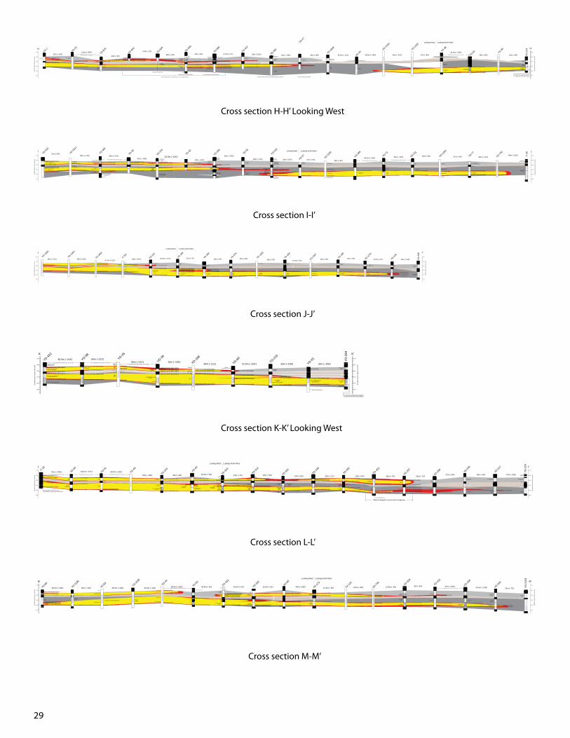
29
Fine - Coarse(sand)
2.29m (7.5') of 0.14% @84.6m (277.5')0.61m (2.0') of 0.06% @87.8m (288.0')0.30m (1.0') of 0.03% @90.7m (297.5')
0.46m (1.5') of 0.03% @94.8M (311.0')0.46m (1.5') of 0.18% @95.9m (314.5')
0.61m (2.0') of 0.28% @104.6m (343.0')
0.46m (1.5') of 0.09% @92.7m (304.0')0.30m (1.0') of 0.05% @93.9m (308.0')
1.07m (3.5') of 0.28% @96.0m (315.0')
0.46m (1.5') of 0.39% @104.0m (341.0')
Very fine - Fine (sand)
Corrected w/ Res
Mudstone from Res
Fine(sand)
As above
32m (~105')111m (~364')
Note: YD-878, 877 & 876 are between these holes,but data was poor or un-available
Medium - gran (VC)(sand)
local rusty stn.
1.52m (5.0') of 0.04% @86.1m (282.5')1.52m (5.0') of 0.15% @87.7m (287.5')0.76m (2.5') of 0.02% @89.2m (292.5')0.46m (1.5') of 0.17% @89.9m (295.0)
Silt
Medium - Very coarse (VC)(sand)
Abt Limey zones
1.83m (6.0') of 0.07% @86.4m (283.5')1.98m (6.5') of 0.54% @91.0m (289.5')
Siltbecoming
SandMedium - Pebbly (Gran)
(sand & gravel)gray upper part
Abt pyr, local calc
Medium - Very coarse (C)(sand)
Local gravel
Silty(mudstone)
0.46m (1.5') of 0.10% @91.0m (298.5')1.98m (6.5') of 1.38% @92.2m (302.5')
1.07m (3.5') of 0.04% @103.7m (340.0')0.46m (1.5') of 0.16% @104.7m (343.5')
Silty mud becoming fine sandGray to Lt Gray
Medium - Pebbly (VC)(sand & gravel)Gray. Abt Pyrt
Silt w/ clay mtx. Gray
Medium - Pebbly (VC)(sand & gravel)
Gry top, Light brown lower partAbt pyr, Black U min. visible
Fine - Coarse (M)(sand)
0.46m (1.5') of 0.12% @91.0m (298.5')1.52m (5.0') of 0.93% @91.5m (300.0')
0.76m (2.5') of 0.03% @99.2m (325.5')
0.30m (1.0') of 0.46% @104.0m (341.0')0.76m (2.5') of 0.03% @104.3m (342.0')0.46m (1.5') of 0.59% @105.0m (344.5')
Medium - Coarse(sand)
aa(sand)
1.37m (4.5') of 0.04% @91.0m (298.5')
0.30m (1.0') of 0.08% @98.8m (324.0')
0.30m (1.0') of 0.12% @104.4m (342.5')
Silt and Very fine Sand w/ clay mtx
Fine - Pebbly (VC)(sand)
Minor pyr
1.37m (4.5') of 0.04% @97.6m (320.0')
Medium - Very coarse(sand)
AA(sand)
2.44m (8.0') of 0.47% @100.0m (328.0')
Gray lime lower part.
Abt Pyr upper part.
At roll-front, Turtle Sand
Locally abt pyrw/ hem in lower part.
Just behind Turtle Sand roll-front
Brown LowerAbt Blck U grain coat
Strng mrn to red stn w/ min
Some weak rusty stn & greenish cast near middle
Ahead of Turtle Sand roll-front; Behind Sage Sand roll-front.Turtle Sand roll-front v. sinuous, crosses cross section 3 times. Ahead of Sage Sand roll-front
At or very near Turtle Sand roll-front.
U U
U
U
4.5m (~15')
20m (~66') 16m (~53') 17.5m (~57') 32m (~105') 33m (~108') 30m (~98')
0.61m (2.0') of 0.02% @98.5m (323.0')
0.61m (2.0') of 0.26% @102.7m (337.0')
No sand describedbut likely present
29m (~95')
?
TRC minMin (not calculated)
v trc min
trc minVery coarse
(sand)
AA(mudstone)
Muddy sandfrom Res Log
Fine - Very coarse(sand)
0.30m (1.0') of 0.10% @103.8m (340.5')
0.23m (0.75') of 0.47% @114.5m (375.5')
Silt
Very coarse - Pebbly(sand & gravel)
0.76m (2.5') of 0.16% @99.7m (327.0')
0.30m (1.0') of 0.39% @109.6m (359.5')0.46m (1.5') of 0.87% @111.7m (366.5')
0.46m (1.5') of 0.61% @99.5m (326.5')
Medium - Fine(sand)
Very coarse - Medium(sand)
Pebbly to clayey at bottom
0.46m (1.5') of 0.09% @99.7m (327.0')0.46m (1.5') of 1.51% @105.0m (344.5')
0.46m (1.5') of 1.60% @107.3m (352.0')
34.5m (~113')91.5m (~300')
26m (~85') 18m (~59')
Mudstone? (not described)
YD-2105 is between these holes, but no data.
2,050
2,060
2,070
2,080
2,090
2,100
Ele
vatio
n (m
eter
s ab
ove
sea
leve
l)
H
48.5m (~159') 64m (~210') 27m (~89')
YD-7YD-19
YD-875
YD-603
YD-605
YD-590
YD-589
YD-412
YD-350
YD-27
YD-1848
YD-29YD-12
34
YD-1232
YD-38
YD-52 YX-99
YD
-123
2,050
2,060
2,070
2,080
2,090
2,100
H'
Ele
vatio
n (m
eter
s ab
ove
sea
leve
l)
Bad
sam
ple
desc
riptio
ns, o
nly
min
. dat
a us
ed
Pap
er g
amm
a an
d re
sist
ivity
logs
onl
y
Pap
er g
amm
a an
d re
sist
ivity
logs
onl
y
Fine - Very coarse(sand)
Medium - Fine(muddy sand)
Looking West Looking North-West
Medium(sand)
Fine - Pebbly (C - VC)(sand)
Cross section H-H’ Looking West
Very coarse -Gritty (sand), gray
Mudstone(interpreted from Res log)
0.30m (1.0') of 0.06% @84.9m (278.5')
0.61m (2.0') of 0.13% @89.3m (293.0')
0.30m (1.0') of 0.13% @103.5m (339.5')
Silt becomingFine - Medium sand
clay mtx
Medium - Pebbly,Granule(sand & gravel)
Very fine - (Medium)(sand)
BleachedLocally tan
w/ strong rusty stn
1.52m (5.0') of 0.04% @87.2m (286.0')
0.46m (1.5') of 0.05% @92.1m (302.0')
0.61m (2.0') of 0.01% @97.3m (319.0')
0.61m (2.0') of 0.05% @103.4m (339.0')
Mudstone (Depths adjusted)
0.30m (1.0') of 0.13% @87.7m (287.5')
0.46m (1.5') of 0.69% @91.0m (298.5')
0.30m (1.0') of 0.07% @96.3m (316.0')
0.76m (2.5') 1.26% @102.4m (336.0')
MudstoneLime beds
locally high pyrt
Sand: Fine - G(sand)
avg. size increase w/ depthPyr, small carb
Fine - Coarse(sand)
carb, pyrt
Coarse - Pebbly(sand & gravel)sm carb & pyrt
Silty to fine(sand)
abt carb
1.52m (5.0') of 0.20% @90.9m (298.0')
0.76m (2.5') of 0.30% @97.6m (320.0')
0.61m (2.0') of 3.39% @101.4m (332.5')
Silty to Fine top(sand)
Pebbly @Bottom
2.13m (7.0') of 0.59% @101.2m (332.0')
trace
Mudstone(Locally silty)
Mudstone (described as silt)minor pyr
Sand: Very fine - Medium(sand)
minor pyr
Mudstone(becomming silty to
sandy at bottom)
3.05m (10.0') of 0.34% @102.0m (334.5')
3.35m (11.0') of 0.64% @109.3m (358.5')
0.61m (2.0'0 of 0.08% @114.6m (376.0')
Silty-Pebbly(sand)
0.46m (1.5') of 0.30% @106.6m (349.5')
Local v wht & calce upper part.
Micaceous w/ abt carbtrash and clay 365-78
Pebbls @ base
32m (~105')32.5m (~105')
33m (~110')
32m (~105')
33m (~110') 31m (~100')
Mudstone (described as silt)
mineral (not calculated)
Fine - Very coarse (C-VC)(sand)
minor bleach, moderate rusty stn bottom
Likely mudstone described as "Silt-F w/ clay."
Sand: Fine - Very coarse (M-C)(sand)
335-350 (smpls) strong rusty stn.
0.61m (2.0') of 0.03% @86.3m (283.0')
0.61m (2.0') of 0.02% @94.8m (311.0')
0.30m (1.0') of 0.06% @100.3m (329.0')
0.91m (3.0') of 0.17% @108.2m (355.0')
Sand & Gravel w/ silt & clay Minor CaCO3 bottom.
Medium - Pebbly (VC)(sand &gravel)
Rusty stn.
Mudstonev(described as mud and sand)
Fine - Very coarse (C)(sand)
Moderate to strong rusty stn.
Coarse - (Very coarse)(sand)
Upper w/ abt pyr & blck U min
Silt to coarse sand w/ clay mtxminor rust top, limey middle,
Abt carb wood
Mudstone (gray)
0.46m (1.5') of 0.03% @93.1m (305.5')
0.61m (2.0') of 0.03% @89.6m (294.0')
0.46m (1.5') of 0.69% @106.7m (350.0')0.30m (1.0') of 0.33% @108.2 (355.0')
Musdstone (from RES)
Sand (from RES)
Sand (from RES)
wk min (from gamma)
mineral (from gamma), grade not known
No upper min
No upper min
Lower part bleached w/ mod rusty stn
27m (~90')35m (~115') 65m (~213')
0.46m (1.5') of 0.08% @104.0m (341.0')
0.30m (1.0') of 0.38% @115.5m (379.0')
0.30m (1.0') of 0.27% @103.0m (338.0')
0.30m (1.0') of 0.17% @113.3m (371.5')
Coarse(sand)
Fine- Very coarse(sand)
0.30m (1.0') of 0.28% @102.4m (336.0')
0.30m (1.0') of 0.31% @111.4m (365.5')
Mud and Sand(most likely sand on top of mud)
Very coarse, Clean(sand)
0.61m (2.0') of 0.04% @101.8m (334.0')
0.30m (1.0') of 0.73% @110.1m (361.0')
InterbeddedMudstone and Sand
Fine - Coarse(muddy sand)wk min (from gamma)
min (from gamma)
mudstone (from res)
Sand (from RES)
Muddy sand (from RES)
Mudstone (from RES)
Sand (from RES)
Min (gamma spike)
wk min (gamma spike)
Muddy Sand (RES)
Clean Sand (RES)
Mudstone
Mudstone (RES)
Sand (RES)
Mudstone(not described)
21m (~70') 26m (~85')45.5m (~150') 46m (~151') 20m (~65') 27m (~90') 33m (~110')
40m (~130')
Looking West Looking North-West
YD-1016 between these holes, but no data
Siltyinterval
YD-1254 between these holes, but no dataYD-1257 between these holes, but no data
2,050
2,060
2,070
2,080
2,090
2,100
Ele
vatio
n (m
eter
s ab
ove
sea
leve
l)
I
2,050
2,060
2,070
2,080
2,090
2,100
I'
Ele
vatio
n (m
eter
s ab
ove
sea
leve
l)
YD-410
YD-1017
YD-404
YD-30
YD-376
YD-32
YD-305
YD-55
YD-322
YD-57 YD-1250
YD-189
YD-73
YD-211
YD-1260
YD-77
YD-750
F-20
No
Sam
ple
Log
or R
ES
. Poo
r Gam
ma
Log.
Coarse(sand)
Sandy silt
Fine - Very coarse(sand)
Medium - Gran.(sand & gravel)Local Pebbles
abt very fine - fine pyr
Medium - Gran.(sand & gravel)
Local very fine - fine pyr
Fine - Coarse(sand)
Cross section I-I’
Gamma rerun (scale unknown)
Trace
Gamma spike (5k rerun) Trace min
5k rerun
Gamma spike Trace
Gamma spike, unknown gradeGamma spike, unknown grade
Gamma spike, unknown grade
Mudstone
SandFine - Coarse
(sand) Pyr. Carb
Fine - Coarse(sand)
0.61m (2.0') of 0.33% @87.8m (288.0')
0.30m (1.0') of 0.11% @91.6m (300.5')
0.46m (1.5') of 0.05% @102.9m (337.5')
Mudstone
Medium - Very coarse(sand)
Fine grading to Coarseand clean (sand)
2.90m (9.5') of 0.90% @88.9m (291.5')
0.61m (2.0') of 0.20% @96.3m (316.0')
0.30m (1.0') of 1.09% @111.4m (365.5')
Trace
65m (~213') 65m (~213') 65m (~213')67.5m (~221')
64.5m (~212')
Coarse(sand)
Fine - Coarse and gritty(sand)
0.30m (1.0') of 0.95% @114.8m (376.5')
Medium - Coarse(sand)
Medium - Coarse(sand)
Coarse - Very coarse(sand)
0.30m (1.0') of 0.03% @99.5m (326.5')2.29m (7.5') of 0.16% @102.3m (335.5')0.46m (1.5') of 0.04% @105.0m (344.5')
0.30m (1.0') of 0.08% @115.2m (378.0')
Sand and
Gravel
1.68m (5.5') of 0.11% @103.4m (339.0')
0.76m (2.5') of 0.18% @114.8m (376.5')
Fine - Coarse(sand)
Silt
Silty sand(From Res Log)
1.37m (4.5') of 0.03% @102.4m (336.0')
0.30m (1.0') of 0.42% @112.7m (369.5')
Coarse - Fine(sand)
Medium - Very coarse(sand)
0.46m (1.5') of 0.27% @103.8m (340.5')
0.30m (1.0') of 0.29% @111.9m (367.0')
Medium - Fine(sand)
Medium(sand)
CoarseClean(sand)
0.61m (2.0') of 0.08% @105.2m (345.0')2.74m (9.0') of 0.24% @105.8m (347.0')
1.83m (6.0') of 0.06% @108.5m (356.0')
0.30m (1.0') of 0.03% @114.6m (376.0')
Fine - Very coarse(sand)
Mudstone(from Res log)
Poor sand (RES)
Sandcleanest between
mineral (RES)
Mudstone (RES)
Min (gamma)
Mineral (gamma)
Sand (from RES)
Mudstone
Sand
Min (from gamma, not calculated)
Mineral (from Gamma, not calculated)
Sand(not described, from RES)
23m (~75') 18m (~59') 26m (~85') 26m (~85') 19.5m (~64')26m (~85') 20m (~66') 26.5m (~87') 45m (~148')
0.46m (1.5') of 1.57% @99.5m (326.5')0.30m (1.0') of 9.27% @101.1m (331.5')0.30m (1.0') of 3.84% @102.0m (334.5')0.76m (2.5') of 2.36% @103.0m (338.0')0.61 (2.0') of 3.71% @104.9m (344.0')
YD-1064
YD-1063
YD-1062
F-22c
YD-197
YD-199
YD-339
YD-576
YD-1263
YD-284
YD-1267
YD-186
YD-1270
YD-109
YD
-208
2,050
2,060
2,070
2,080
2,090
2,100
J
Ele
vatio
n (m
eter
s ab
ove
sea
leve
l)
2,050
2,060
2,070
2,080
2,090
2,100
J'
Ele
vatio
n (m
eter
s ab
ove
sea
leve
l)
Gam
ma
and
poor
resi
stiv
ity lo
g on
ly
Gam
ma
and
resi
stan
ce lo
g on
ly
Gam
ma
log
only
, sca
le u
nkno
wn
Poo
r sam
ple
desc
riptio
ns
From
sca
nned
log
Fine - Coarse(sand)
From
sca
nned
log
Fine - Very coarse(sand)
Looking West Looking North-West
Cross section J-J’
Clay (MS) becomingsilt to Fine sand
Fine - Very coarse (M-C) (sand)Tan Mod to strong rusty stn
Very fine - Very coarse (M-C) (sand)Tan w/ mod rusty stn top 1/2
0.61m (2.0') of 0.01% @86.9m (285.0')
0.46m (1.5') of 0.01% @93.6m (307.0')1.52m (5.0') of 0.01% @96.0m (315.0')
0.76m (2.5') of 0.15% @105.3m (345.5')
Medium - Coarse(sand)
0.46m (1.5') of 0.03% @84.0m (275.5')
0.46m (1.5') of 0.04% @90.5m (297.0')
0.46m (1.5') of 0.05% @96.6m (317.0')
1.07m (3.5') of 0.04% @105.2m (345.0')
Fine - Very coarse (sand)
and pebbly
Sand: AA
0.91m (3.0') of 0.05% @85.4m (280.0')2.29m (7.5') of 0.16% @86.3m (283.0')0.46m (1.5') of 0.46% @88.1m (289.0')0.46m (1.5') of 0.21% @91.3m (299.5')
0.30m (1.0') of 0.09% @95.0m (311.5')
Mudstone
Sand
MudstoneBlue - Gray
0.30m (1.0') of 0.10% @87.8m (288.0')0.30m (1.0') of 0.25% @90.5m (297.0')
0.61m (2.0') of 0.05% @95.3m (312.5')
0.46m (1.5') of 0.05% @111.7m (366.5')
Mudstone(described as sand and silt)
2.29m (7.5') of 0.28% @88.7m (291.0')
0.61m (2.0') of 0.07% @ 96.0m (315.0')`
0.91m (3.0') of 1.08% @101.5m (333.0')
0.30m (1.0') of 0.24% @111.3m (365.0')
Very coarse(sand)
Fine - Medium(sand)
Very coarse - Scat Pebbles
1.22m (4.0') of 0.04% @97.6m (320.0')0.46m (1.5') of 0.85% @100.5m (329.5')
0.30m (1.0') of 0.14% @112.7m (369.5')
Sand - Top depth correctedbased on Gamma.
0.46m (1.5') of 0.08% @102.4m (336.0')
0.46m (1.5') of 0.05% @112.0m (367.5')
Fine - Coarse(sand)
Silt (Clayey)
Sand (silty)(From Res Log)
1.37m (4.5') of 0.03% @102.4m (336.0')0.30m (1.0') of 0.42% @112.7m (369.5')
Lt Gray-Tan w/ local bleaching lower 1/2
Mudstone
Sand(RES)
Mudstone(RES)
Min (gamma)
Min (gamma)
Min (gamma)
Sand (described as mud)Poor res.
Sand(described as sand and silt)
No RES, depths may be off.
Sand (not described)
65.5m (~215') 65m (~213')65m (~213') 32m (~105')
34m (~112') 31.5m (~103') 33m (~108') 32m (~105')YD-1105 between these holes, but no data YD-1104 between these holes, but no data
YD-1103 between these holes, but no data
0.23m (0.75') of 0.49% @110.1m (361.0')
2,050
2,060
2,070
2,080
2,090
2,100
K'E
leva
tion
(met
ers
abov
e se
a le
vel)
YD-422
YD-98YD-35
YD-39
YD-198
YD-60 YD-215
YD-61 YD
-284
Scan
ned
log
only
Sand(RES)
Bad
sam
ple
desc
riptio
ns, N
o. R
es.
Lith
. est
imat
ed u
sing
gam
ma
Sand
Fine - Coarse(sand)
2,050
2,060
2,070
2,080
2,090
2,100
K
Ele
vatio
n (m
eter
s ab
ove
sea
leve
l)
Cross section K-K’ Looking West
0.46m (1.5') of 0.04% @83.8m (275.0')
0.46m (1.5') of 0.04% @86.9m (285.0')
0.30m (1.0') of 0.04% @93.0m (305.0')0.30m (1.0') of 0.07% @95.4m (313.0')
0.30m (1.0') of 0.57% @105.2m (345.0')Grades from medium at top
to pebbly at bottom
Siltvery abt pyrite
LimestoneCoarse - Pebbly(sand & gravel)
Grey-Tan, minor pyr
Very fine - Coarse(sand)Abt Pyr
Medium - Pebbly(sand & gravel)
Gray-Tan.
Sand & silt
Medium - GranulesGray-Tanminor pyr
Coarse - Pebbly(sand & gravel)
gray-tanminor pyr
1.52m (5.0') of 0.05% @100.9m (331.0')0.76m (2.5') of 0.37% @102.4m (336.0')
Medium -Granule(sand &gravel)Minor rusty stn.
Very fine - Medium(sand)pyritic
Very fine - Very coarse(sand)Abt Pyr
Silty, Very fine - Medium(sand)Pyritic
0.91m (3.0') of 0.09% @87.7m (287.5')0.61m (2.0') of 0.23% @89.2m (292.5')0.30m (1.0') of 0.04% @90.7m (297.5')
0.46m (1.5') of 0.24% @102.7m (337.0')
0.30m (1.0') of 0.31% @110.7m (363.0')
1.98m (6.5') of 0.07% @86.4m (283.5')
0.30m (1.0') of 0.27% @102.3m (335.5')
0.46m (1.5') of 0.06% @107.6m (353.0')
2.44m (8.0') of 0.06% @86.6m (284.0')
2.29m (7.5') of 0.51% @95.7m (314.0')
1.52m (5.0') of 0.22% @111.0m (364.0')0.76m (2.5') of 0.06% @113.4m (372.0')
Coarse - Very fine(muddy sand)
Very coarse, Clean(sand)
Interbeddedclay and sand
Mudstone(Not described)
Silty mudstone(Not described)
Coarse(sand)
0.30m (1.0') of 0.06% @86.7m (284.5')
0.61m (2.0') of 0.04% @92.2m (302.5')
0.61m (2.0') of 0.07% @98.3m (322.5')
1.52m (5.0') of 0.04% @83.8m (275.0')
0.61m (2.0') of 0.25% @108.2m (355.0')0.46m (1.5') of 0.05% @108.8m (357.0')
Fine - Medium - Coarse(sand)
Very fine - Medium(sand)
Very coarse - Medium,pebbles(sand &gravel)
0.46m (1.5') of 0.28% @85.7m (281.0')
0.30m (1.0') of 0.07% @90.2m (296.0')
0.30m (1.0') of 0.13% @95.0m (311.5')
0.30m (1.0') of 0.05% @110.5m (362.5')
0.46m (1.5') of 0.06% @85.4m (280.0')
0.30m (1.0') of 0.14% @89.5m (293.5')
2.44m (8.0') of 0.90% @96.3m (316.0')
0.23m (0.75') of 0.55% @110.5m (362.5')
0.61m (2.0') of 0.04% @90.1m (295.5')
0.30m (1.0') of 0.16% @97.4m (319.5')
1.52m (5.0') of 1.15% @100.3m (329.0')
0.76m (2.5') of 0.03% @110.8m (363.5')
1.83m (6.0') of 0.01% @85.7m (281.0')
0.61m (2.0') of 0.56% @90.7m (297.5')
1.22m (4.0') of 0.07% @110.1m (361.0')
Fine - Coarse(sand)
0.30m (1.0') of 0.05% @84.9m (278.5')
1.07m (3.5') of 0.74% @90.7m (297.5')
0.91m (3.0') of 0.02% @96.0m (315.0')
0.46m (1.5') of 0.10% @103.0m (338.0')
1.22m (4.0') of 0.19% @109.8m (360.0')
Fine - Coarse (sand)(muddy sand)
2.74m (9.0') of 0.26% @88.1m (289.0')
2.59m (8.5') of 0.66% @97.0m (318.0')
0.30m (1.0') of 0.05% @104.4m (342.5')
1.98m (6.5') of 0.83% @107.8m (353.5')
3.66m (12.0') of 0.06% @ 109.8m (360.0')3.51m (11.5') of 0.19% @106.9m (350.5')
3.66m (12.0') of 0.02% @110.4m (362.0')
0.46m (1.5') of 0.03% of 109.8m (360.0')Entire sequence described as Clay.Sands based on gamma and closest holes.
Trace min 109.8m-111.3m (360-65')
Trace
Trace
Abt pyrBlack UO2
Grain Coatings
Sand (describedas mudstone)
Sand (described as
mudstone)
Poor Sample Descriptions
1.83m (6.0') of 1.52% @107.6m (353.0')
81m (~266') 64.5m (~212') 64.5m (~212')
33m (~108') 30m (~98') 16.5m (~54') 24m (~79') 18m (~59') 19m (~62') 22m (~72') 16m (~53') 23m (~75') 22m (~72')21m (~69') 18m (~59') 72m (~236')YD-1182 between these holes, but no data YD-1181 between holes, but no data YD-1180 between these holes, but no data
From map ofStope 407
F-23
YD-94
YD-41
YD-43
YD-213
YD-63
YD-315
YD-314
YD-320
YD-146
YD-262
YD-252
YD-257
YD-258
YD-245
YD-217
YD
-224
2,050
2,060
2,070
2,080
2,090
2,100
L
Ele
vatio
n (m
eter
s ab
ove
sea
leve
l)
2,050
2,060
2,070
2,080
2,090
2,100
L'
Ele
vatio
n (m
eter
s ab
ove
sea
leve
l)
Coarse(sand)
Pebbly @ bottomCoarse(sand)
Fine(sand)
Gam
ma
only
From map ofStope 407
Looking West Looking North West
Very fine - Medium(sand)
Medium -Granules(sand &gravel)
local pebsv abt pyr
0.30m (1.0') of 0.43% @90.1m (295.5')
Coarse(sand)
Mudstone on lith logs, but mining maps indicate no Eucalyptus clay
Fine - Coarse(sand)
Fine - Coarse(sand)
Very fine(muddy sand)
(mudstone)
Coarse(sand)
Fine - Coarse(sand)
Very Coarse - Medium(sand)
Very Coarse(sand)
Very Coarse - Medium(sand)
Very Coarse(sand)
Cross section L-L’
Medium(sand)
0.23m (0.75') of 0.39% @86.3m (283.0')0.30m (1.0') of 0.36% @88.3m (289.5')
0.30m (1.0') of 0.05% @92.4m (303.0')
0.30m (1.0') of 0.18% @107.8m (353.5')
0.91m (3.0') of 0.08% @108.4m (355.5')
Medium - Fine(sand)
Mudstone
Sand (describe as mud)
Mudstone0.61m (2.0') of 0.02% @91.2m (299.0')
0.30m (1.0') of 0.10% @98.6m (323.5')
0.30m (1.0') of 0.46% @11.3m (365.0')
Medium - Fine(sand)
Some Very fine
Sand&
Silt
0.30m (1.0') of 0.04% @97.3m (319.0')
0.30m (1.0') of 0.35% @110.7m (363.0')
Fine - Medium(sand)
Medium - Very coarse(sand)
0.30m (1.0') of 0.38% @88.3m (289.5')0.76m (2.5') of 0.04% @88.6m (290.5')
0.30m (1.0') of 0.06% @90.5m (297.0')0.46m (1.5') of 0.24% @93.3m (306.0')
0.30m (1.0') of 0.31% @98.3m (322.5')
0.46m (1.5') of 0.37% @109.9m (360.5')
Sand,Clay & Silt
Very silty but overallcoarser than above
(sand)
Fine(sand)
Sand much coarser than above
0.46m (1.5') of 0.03% @85.8m (281.5')
0.30m (1.0') of 0.06% @91.5m (300.0')
3.51m (11.5') of 0.55% @97.9m (321.0')0.76m (2.5') of 0.03% @101.4m (332.5')
0.61m (2.0') of 0.04% @109.5m (359.0')0.30m (1.0') of 0.39% @110.1m (361.0') Sand Pebbly
at bottom
0.30m (1.0') of 0.09% @84.5m (277.0')0.46m (1.5') of 0.35% @85.4m (280.0')
0.76m (2.5') of 0.35% @89.6m (294.0')
0.61m (2.0') of 0.37% @100.3m (329.0')0.30m (1.0') of 7.93% @102.0m (334.5')
0.76m (2.5') of 0.03% @108.7m (356.5')
Coarse Pebbly(sand & gravel)
Fine(muddy sand)
Coarse(sand)
Gray to BrownClean
0.76m (2.5') of 0.19% @84.5m (277.0')
0.76m (2.5') of 0.86% @89.6m (294.0')
0.30m (1.0') of 1.53% @102.0m (334.5')
1.22m (4.0') of 1.23% @109.9m (360.5')
0.46m (1.5') of 0.61% @86.3m (283.0')
0.30m (1.0') of 0.33% @91.8m (301.0')
0.46m (1.5') of 0.31% @103.5m (339.5')
0.76m (2.5') of 2.24% @110.7m (363.0')
Pebbly topmedium lower part
(sand & gravel)
Pebbly( sand & gravel)
0.30m (1.0') of 0.30% @90.2m (296.0')
0.61m (2.0') of 0.09% @103.0m (338.0')
2.74m (9.0') of 0.38% @108.7m (356.5')
Muddy sand
2.29m (7.5') of 0.44% @87.3m (286.5')
0.30m (1.0') of 0.24% @103.5m (339.5')
1.68m (5.5') of 1.47% @108.2m (355.0')Very coarse - Pebbly
(sand & gravel)
0.30m (1.0') of 0.33% @105.2m (345.0')
0.30m (1.0') of 2.29% @111.6m (366.0')
Fine to Mediumto Very Coarse
(sand)
Very fine(muddy sand)
Medium - Very coarse Clean(sand)
0.76m (2.5') of 0.76% @109.6m (359.5')2.44m (8.0') of 1.11% @111.3m (365.0')
Fine - Coarse(sand)
0.30m (1.0') of 2.25% @108.1m (354.5')Sand (described as mud)
Mudstone (not described)
Sand (from RES)
Mudstone (from RES)
Sand (from RES)
Clean Sand (from RES)
Mineral (from Gamma)
Mineral (from Gamma)
Mineral (from Gamma)
Mudstone (not described)
Mudstone (described as sand)
Mudstone (not described)
Mineral (Gamma)
Mineral (Gamma)
Mineral (Gamma)Mineral (Gamma)
Mudstone? (not described)
30.5m (~100') 35m (~115') 30.5m (~100') 33.5m (~110') 69.5m (~228') 28.5m (~94') 16.5m (~54') 15.5m (~51') 33m (~108') 14.5m (~48') 8.5m (~28') 14.5m (~48') 8m (~26') 47m (~154') 42.5m (~139') 23m (~75')YD-749 between these holes, but no data
Trc min
YD-85
2,050
2,060
2,070
2,080
2,090
2,100
M
Ele
vatio
n (m
eter
s ab
ove
sea
leve
l)
2,050
2,060
2,070
2,080
2,090
2,100
M'
Ele
vatio
n (m
eter
s ab
ove
sea
leve
l)
YD-1196
YD-83 YD-1195
YD-44
YD-53YD-18
2
YD-332
YD-66Looking West Looking North West
YD-172
YX-110
YD-744
YD-318
YD-151
YD-156
YD-244
YD
-210
3
No
scan
ned
log
aval
iabl
e.M
iner
al n
ot re
cord
ed
Bad
sam
ple
desc
ripiti
ons
Min
eral
not
reco
rded
Bad
sam
ple
desc
ripiti
ons
YD-1194 between these holes, but no data
Medium - Very coarse(sand)
Sand&
Silt
Bad
sam
ple
desc
ripiti
ons
No
sam
ple
desc
ripiti
ons,
gam
ma
log
only
Fine - Medium(sand) Muddy sand Fine
(muddy sand)
Cross section M-M’
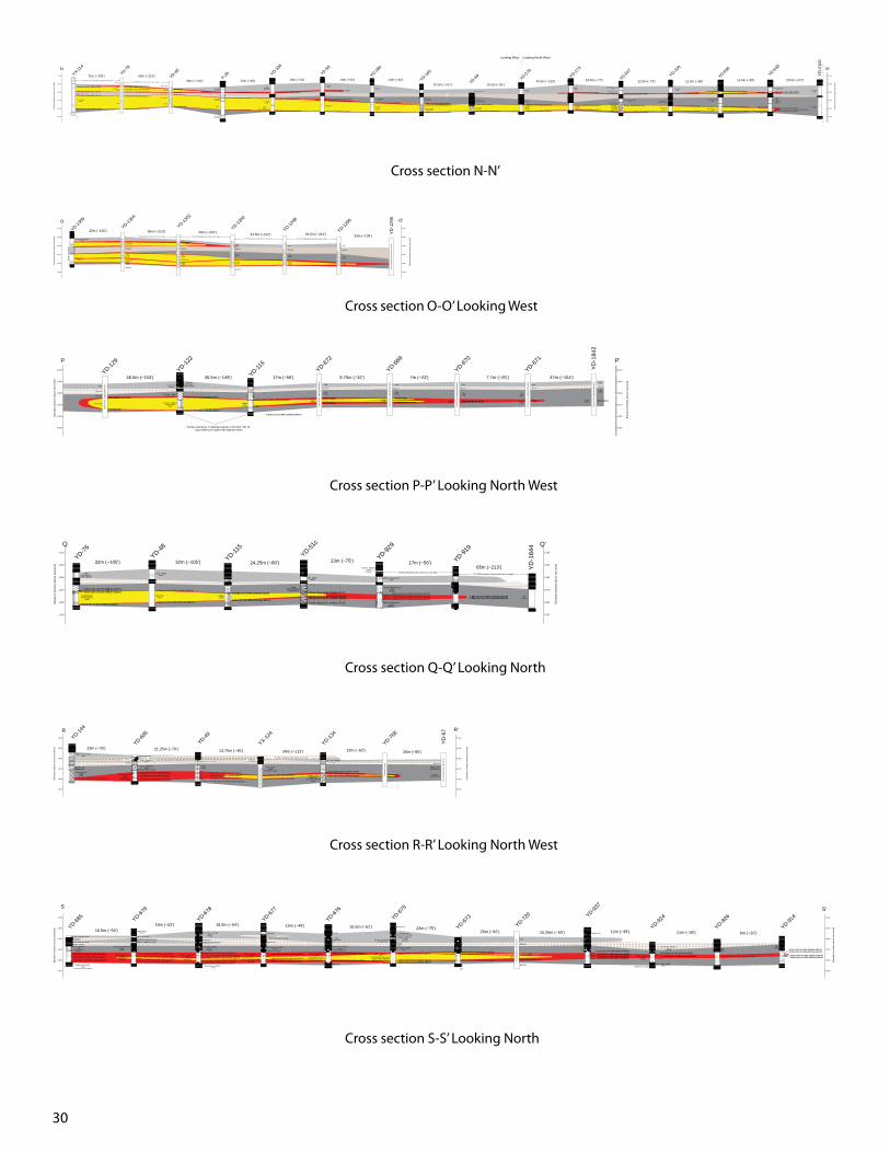
30
Fine - Medium(sand)
0.30m (1.0') of 0.07% @85.7m (281.0')
0.76m (2.5') of 0.03% @91.8m (301.0')
0.91m (3.0') of 0.06% @95.7m (314.0')
0.46m (1.5') of 0.67% @113.0m (370.5')
1.83m (6.0') of 0.02% @83.8m (275.0')
0.15m (0.5') of 0.11% @88.3m (289.5')
0.30m (1.0') of 0.14% @91.9m (301.5')
0.30m (1.0') of 0.54% @96.8m (317.5')
0.46m (1.5') of 0.46% @112.8m (370.0')
Coarse(sand)
Fine - Coarse(muddy sand)
1.37m (4.5') of 0.14% @90.4m (296.5')
0.30m (1.0') of 0.09% @97.3m (319.0')
0.46m (1.5') of 0.36% @112.3m (368.5')
Sand(described as sand and silt)
Fine - Medium(sand)
Coarse(sand)
Much Coarser than above
2.13m (7.0') of 0.05% @89.8m (294.5')
0.30m (1.0') of 0.29% @98.5m (323.0')
1.37m (4.5') of 0.26% @112.5m (369.0')
Silty - Medium(sand)
Medium - Pebbly(sand)
1.22m (4.0') of 0.02% @87.2m (286.0')
1.37m (4.5') of 0.97% @98.0m (321.5')0.91m (3.0') of 0.46% @99.7m (327.0')
0.30m (1.0') of 0.34% @113.4m (372.0')
Fine - Coarse(sand)
Silt - Fine - Medium(sand)
Fine - Coarse(sand)
Gray to Tan
0.46m (1.5') of 0.24% @102.1m (335.0')
0.30m (1.0') of 0.52% @113.7m (373.0')
Fine - Medium( muddy sand)
Very coarse - Pebbly(sand & gravel)
0.30m (1.0') of 0.37% @103.2m (338.5')0.61m (2.0') of 1.25% @104.9m (344.0')
0.23m (0.75') of 1.83% @113.5m (372.3')
Muddy Sand(described as mudstone)
Coarse - Pebbly(sand & gravel)
0.30m (1.0') of 5.54% @111.4m (365.5')
Fine - Coarse(sand)
Silty Sand
Fine - Coarse(sand)
Gray to Brown
0.61m (2.0') of 0.03% @103.7m (340.0')
0.30m (1.0') of 0.63% @111.4m (365.5')
Medium(sand)
Coarse, Clean(sand)
1.07m (3.5') of 0.04% @87.8m (288.0')
0.30m (1.0') of 0.28% @103.5m (339.5')
0.46m (1.5') of 3.07% @108.8m (357.0')
Silty, Very fine - Coarse (M)(sand)
Gravelly, Fine - Gran (C)(sand)
Silty, Very fine - Coarse (M)(sand
Very fine - Very coarse(sand & gravel)
Scarce pyrFine - Pebbly (C)(sand & gravel)
Black U min.
1.22m (4.0') of 0.03% @89.3m (293.0')
0.91m (3.0') of 0.58% @111.6m (366.0')
Fine - Coarse(sand)
Muddy Sand(described as mudstone)
0.76m (2.0') of 1.00% @88.9m (291.5')
0.30m (1.0') of 0.23% @104.3m (342.0')
0.30m (1.0') of 0.42% @110.7m (363.0')
Medium - Very coarse (C)(sand)
Silty, Very fine - Medium(sand)
Medium - (Very coarse)(sand)
0.91m (3.0') of 0.12% @87.0m (285.5')1.07m (3.5') of 0.51% @89.2m (292.5')
0.91m (3.0') of 0.15% @105.8m (347.0')
0.61m (2.0') of 0.51% @111.4m (365.5')
Very fine - Medium (M)(sand)
Medium - (Very coarse)(sand)
Silty, Very fine - (M)(sand)
Minor pyrFine - (Medium)
(sand)
Medium - (Very coarse)Some alt near 360'
Silty, (Fine )- Medium(sand)
0.61m (2.0') of 1.24% @88.4m (290.0')0.61m (2.0') of 0.26% @89.0m (292.0')
0.91m (3.0') of 0.18% @107.3m (352.0')(Between tails). 2.13m (7.0') of 0.03% @108.2m (355.0')1.52m (5.0') of 0.13% @110.4m (362.0')
Fine - Medium(sand)
Muddy ZoneSand
Mudstone
Sand
Sand
Mudstone (not described)
Mudstone
Min (gamma)
Min (gamma)
Wk Min (gamma)
Mudstone (RES)
Sand (RES)
Mudstone (RES)
Poor Sand (RES)
Sand (RES)
Trace Min (Gamma)
Mudstone (not described)
Sand (not described)
Minor red to whitecalc 365-70
71m (~233') 65m (~213')34m (~110') 15m (~49') 16m (~53') 19m (~62') 13m (~42')
32.5m (~107') 10.5m (~35')
Looking West Looking North West
40.5m (~133') 23.5m (~77') 22.5m (~73') 11.5m (~38') 11.5m (~38') 20.5m (~67')No data for YD-1209 which is between thes holesYD-1208 between these holes, but no data
No upper gamma signatureNo upper mineral/ gamma spike
2,050
2,060
2,070
2,080
2,090
2,100
N
Ele
vatio
n (m
eter
s ab
ove
sea
leve
l)
2,050
2,060
2,070
2,080
2,090
2,100
N'
Ele
vatio
n (m
eter
s ab
ove
sea
leve
l)
YX-114
YD-78
YD-45
F-35 YD-336
YD-50
YD-280
YD-160
YD-69 YD-279
YD-173
YD-547
YD-106
YD-636
YD-633
YD
-210
0
Poo
r des
crip
tion,
bas
ed li
th. o
n re
sisi
tivity
No
sam
ple
desc
riptio
ns.
Bas
ed li
th. o
n re
s. a
nd g
amm
a lo
gs
Fine - Coarse(sand)
Fine - Coarse(muddy sand)
Fine - Coarse(muddy sand)
Medium - Coarse(sand)
Cross section N-N’
Medium - Fine(sand)
Fine top to Coarse bottom(sand)
Min
eral
not
reco
rded
Sand (RES)
Mudstone
Fine(Sand)
Muddy SandCoarse(sand)
Mudstone
Coarseing downward(sand)
Sand
Mudstone
Mudstone
32m (~105') 65m (~213') 65m (~213') 64.5m (~212') 64.5m (~212')YD-1303 between these holes, but no data YD-1301 between these holes, but no data
YD-1299 between these holes, but poor data YD-1297 between these holes, but no data
2,050
2,060
2,070
2,080
2,090
2,100
O
Ele
vatio
n (m
eter
s ab
ove
sea
leve
l) 33m (~108')
2,050
2,060
2,070
2,080
2,090
2,100
O'
Ele
vatio
n (m
eter
s ab
ove
sea
leve
l)
No s
ampl
e de
scrip
tion,
sca
nned
log
only.
Lith
olog
y/ M
iner
al fr
om re
s. a
nd g
amm
a.
No
sam
ple
desc
riptio
n, s
cann
ed lo
g on
ly.
Lith
olog
y/ M
iner
al fr
om re
s. a
nd g
amm
a.
No
sam
ple
desc
riptio
n, s
cann
ed lo
g on
ly.
Lith
olog
y/ M
iner
al fr
om re
s. a
nd g
amm
a.
Poo
r sam
ple
desc
riptio
nsLi
thol
ogy/
Min
eral
from
sca
nned
log.
No
sam
ple
desc
riptio
nsLi
thol
ogy/
Min
eral
from
sca
nned
log.
YD-1305
YD-1304
YD-1302
YD-1300
YD-1298
YD-1296
YD
-129
5P
aper
Gam
ma
and
Res
istiv
ity L
og o
nly
Mudstone
Fine(Sand)
Muddy Sand
Coarse(sand)
Fine(Sand)
Coarse(sand)
Sand
Mudstone
Fine(Sand)
Coarse(sand)
Sand
Mudstone
Fine(Sand)
Coarse(sand)
Cross section O-O’ Looking West
Silty sand(described as
sandy mudstone)Coarse - Fine(sand)
Very coarse - Medium(mud & sand)
Very coarse - MediumGritty to Pebbly
(sand)
1.22m (4.0') of 0.21% @97.6m (320.0')
0.46m (1.5') of 0.30% @109.8m (360.0')
Medium(sand)
0.61m(2.0') of 0.95% @100.2m (328.5')
0.46m (1.5') of 0.09% @105.9m (347.5')
Coarse sand
Fine Sand
Sand
Mudstone
High gamma (5k rerun)
Gamma spike
Gamma spike
Gamma spike
Sand
Mudstone
Fine(sand)
Coarse(sand) Double peaked gamma
Gamma spikeHigh Gamma (5k rerun) Trace No Gamma
Surface elevations in database appear to be 5.8m (19') off.Logs shifted up to agree with adjacent holes.
46.5m (~153') 45.5m (~149') 17m (~56') 9.75m (~32') 7m (~23') 7.7m (~25')
2,050
2,060
2,070
2,080
2,090
2,100
Ele
vatio
n (m
eter
s ab
ove
sea
leve
l)
P
2,050
2,060
2,070
2,080
2,090
2,100
Ele
vatio
n (m
eter
s ab
ove
sea
leve
l)
P'
trace
YD-129
YD-122
YD-115
YD-672
YD-669
YD-670
YD-671
47m (~154')
Scan
of r
es. a
nd g
amm
a on
lyY
D-1
842
Scan
of r
es. a
nd g
amm
a on
ly
Scan
of r
es. a
nd g
amm
a on
ly
Scan
of r
es. a
nd g
amm
a on
ly
Scan
of r
es. a
nd g
amm
a on
ly
Scan
of r
es. a
nd g
amm
a on
ly Sand
Mudstone
Fine(sand)
Coarse(sand)
Sand
Mudstone
Fine(sand)
Coarse(sand)
Sand
Mudstone
Fine(sand)
Coarse(sand)
Sand
Mudstone
Fine(sand)
Coarse(sand)
Cross section P-P’ Looking North West
Sand(described as
sandy mudstone)
Grading Mediumto Coarse tp Peb
(sand)
0.30m (1.0') of 0.07% @98.5m (323.0')0.61m (2.0') of 0.41% @98.8m (324.0')
4.6m (1.5') of 0.35% @109.6m (359.5')
Coarse - Pebbly(sand)
Coarse (AA)(sand)
0.46m (1.5') of 0.37% @98.2m (322.0')
Silty - pebbly(sand)
PebblyBrown and Black stn
(sand & gravel)0.30m (1.0') of 1.01% @99.8m (327.5')
0.30m (1.0') of 0.29% @102.9m (337.5')0.61m (2.0') of 2.01% @103.8m (340.5')
Very fine - (Medium) (sand)
Some pyr
Medium - (Very coarse)(sand)
Very fine - Medium (Fine)(sand)
Some pyr
Medium - (Very coarse)(sand)
Minor pyr
0.61m (2.0') of 0.76% @101.2m (332.0')1.37m (4.5') of 0.47% @102.3m (335.5')1.07m (3.5') of 1.09% @104.1m (341.5')
1.98m (6.5') of 0.06% @101.5m (333.0')0.30m (1.0') of 0.07% @103.8m (340.5')
0.61m(2.0') of 0.95% @100.2m (328.5')
0.46m (1.5') of 0.09% @105.9m (347.5')Grade data from nearby YD-510.30m (1.0') of 1.28% @107.6m (353.0')
32m (~105') 32m (~105') 24.25m (~80') 23m (~75') 17m (~56')65m (~213')
YD-918 between these holes, but no dataYD-1692 between thses holes, but no data.
YD-76
2,050
2,060
2,070
2,080
2,090
2,100
Q
Ele
vatio
n (m
eter
s ab
ove
sea
leve
l)
2,050
2,060
2,070
2,080
2,090
2,100
Q'E
leva
tion
(met
ers
abov
e se
a le
vel)
YD-48
YD-115
YD-51c
YD-929
YD-919
YD
-184
4
Medium(sand) Fine
(sand)
Cross section Q-Q’ Looking North
Medium - Fine - Coarse(sand)
Medium - Fine(muddy sand)
Fine - Very coarePebbly(sand)
Very fine - Coarse (M)(sand)Mudstone and Silt
some pyr Medium - Pebbly (VC)(sand)
Very fine - Medium (F)(sand)
Strong local bleach. little pyr
Medium - Very coarse(sand)
Few rusty stn near 350'. Abt pyr.
3.81m (12.5') of 0.07% @100.9m (331.0')
1.37m (4.5') of 0.03% @104.7m (343.5')
-or- 7.16m (23.5') of 0.32% @100.5m (329.5')
1.68m (5.0') of 0.49% @101.2m (332.0')0.30m (1.0') of 1.48% @104.9m (344.0')
Mudstone(Scat Carb trash)
Fine - Coarse(sand)
Described as muddy
0.91m (3.0') of 1.46% @104.0m (341.0')
Very coarse - Medium(sand)
Medium - Finegrading to
Very coarse - Medium(sand)
0.91m (3.0') of 0.08% @100.8m (330.5')1.22m (4.0') of 1.55% @101.7m (333.5')
0.30m (1.0') of 5.89% @104.4m (342.5')Gamma peakGamma peak
Muddy or Fine(sand from res)
Coarse(sand from res)
MudstoneMudstone (not described)
1.98m (6.5') of 0.04% @107.6m (353.0') 4.73m (15.5') of 0.09% @106.1m (348.0') 0.30m (1.0') of 1.29% @107.3m (352.0') 0.46m (1.5') of 1.93% @107.3m (352.0')
23m (~75') 21.25m (~70') 13.75m (~45') 34m (~112')YD-555 is between these holes, but no data.
19m (~62') 26m (~85')
2,050
2,060
2,070
2,080
2,090
2,100
Ele
vatio
n (m
eter
s ab
ove
sea
leve
l)
R
2,050
2,060
2,070
2,080
2,090
2,100
R'
Ele
vatio
n (m
eter
s ab
ove
sea
leve
l)
YD-144
YD-685
YD-49
YX-124
YD-134
YD-768
YD
-67
Gam
ma
log
only
Poor
sam
ple
desc
rips,
lith
from
res.
Coarse(sand)
Mudstonesome pyr
Cross section R-R’ Looking North West
Mudstone & SiltSome pyr
Fine - (Coarse) (sand)
Medium - Pebbly (VC) (sand)
Medium-(Very coarse)(sand)
Pyr throughoutLimy zones
3.81m (12.5') of 0.55% @101.2m (332.0')0.15m (0.5') of 0.40% @105.6m (346.5')
0.76m (2.5') of 1.23% @107.0m (351.0')2.74m (9.0') of 0.16% @108.2m (355.0')
Mudstone & siltSilty (mud and sand), Some pyr
0.91m (3.0') of 0.26% @100.8m (330.5')2.74m (9.0') of 1.38% @102.6m (336.5')
0.30m (1.0') of 1.12% @105.9m (347.5')
1.98m (6.5') of 0.15% @109.3m (358.5')
Muddy sand
Medium - Very coarse (C) (sand)
Medium - Pebbly (VC)(sand)
Alt 345-55 (rust stn, tan sand)Hem stn. Some pry upper & lower
Limy zones
4.12m (13.5') of 0.59% @100.9m (331.0')
2.29m (7.5') of 0.34% @108.1m (354.5')
Limestone
Silty(mud & sand)
Medium - Pebbly (VC)(sand)
Altered (minor rusty stain,Tan to Yellow color, grn clay mtx)
Minor pyr top & bottom
3.96m (13.0') of 0.39% @99.7m (327.0')
1.83m (6.0') of 0.56% @107.9m (354.0')
Silt & Silty SandMedium coarse sand locally
Medium - Pebbly (VC)(sand)
Pyr locally
MudstoneSome pyr
Coarse (sand)
1.22m (4.0') of 1.74% @100.8m (330.5')
0.30m (1.0') of 2.55% @108.2m (355.0')0.46m (1.5') of 0.06% @109.8m (360.0')
1.37m (4.5') of 0.22% @99.2m (325.5')1.07m (3.5') of 0.33% @101.1m (331.5')
1.37m (4.5') of 0.64% @107.2m (351.5')
0.61m (2.0') of 0.15% @100.8m (330.5')1.22m (4.0') of 0.94% @101.4m (332.5')0.76m (2.5') of 0.15% @102.6m (336.5')2.9m (9.5') of 0.86% @103.4m (339.0')
Silty, Very fine - Medium (F)(sand)
Some pyr
Medium - (Very coarse)(sand)
Some pyr.
Mudstone (not in cuttings)
0.61m (2.0') of 0.11% @101.8m (334.0')
3.2m (10.5') of 1.66% @102.4m (336.0')
Silty(sand)
3.35m (11.0') of 1.12% @102.0m (334.5')
1.37m (4.5') of 0.05% @100.5m (329.5')0.30m (1.0') of 0.83% @101.8m (334.0')
0.91m (3.0') of 0.05% @102.1m (335.0')0.46m (1.5') of 0.48% @103.0m (338.0')
Very fine - Coarse (M) (sand)
Medium - Pebbly (VC) (sand)
Very fine - Medium (F)(sand)
Strong local bleachlittle pyr
Medium - (Very coarse)(sand)
Few rusty stn near 350'. Abt pyr.
3.81m (12.5') of 0.07% @100.9m (331.0')1.37m (4.5') of 0.03% @104.7m (343.5')
Gamma spikeGamma Spike
Mudstone
Mudstone
Sand
Sand
16.5m (~54')16m (~52') 16.5m (~54') 15m (~49') 15.5m (~51') 23m (~75')
25m (~82') 15.25m (~50') 12m (~39') 11m (~36') 6m (~20')
4.73m (15.5') of 0.09% @106.1m (348.0') 0.76m (1.5') of 0.51% @108.1m (354.5')0.91m (3.0') of 0.15% @107.2m (351.5') High, wide gamma spike
YD-685
2,050
2,060
2,070
2,080
2,090
2,100
S
Ele
vatio
n (m
eter
s ab
ove
sea
leve
l)
YD-679
YD-678
YD-677
YD-676
YD-675
YD-673
YD-720 YD-93
7
YD-924
YD-926
YD-914
2,050
2,060
2,070
2,080
2,090
2,100
S'
Ele
vatio
n (m
eter
s ab
ove
sea
leve
l)
Silty(sand)
Silty, (Very fine) - Medium (sand)
Mudstone & SiltSome pyr
Mudstone, Some pyr
Silty, Very fine - Medium (F) (sand)
Silty, Very fine - Medium (F) (sand)
Bleched
Silty, Very fine - Coarse (M)(sand)
minor pyr
Medium - Pebbly (VC)(sand)
Pyr throughoutLocal calc.
Mudstone & silt
Mudstone & silt
Silty, Very fine - Coarse (M)(sand)
Bleached appearance
Silty (sand)
Silty, Very fine - (Medium)(sand)
Bleached appearance
Mudstone & silt
Scan
ned
gam
ma
and
res.
onl
y.
Silty, Very fine - (Medium)(sand)
Mudstone & silt
Silty, Fine - (Coarse) (sand)Some pyrt locally
Medium - Pebbly (VC)(sand)
Alt. 340-350 (minor rusty stn, tan, grn clay, no pyr, decayed flds)Minor pyr in upper and lower
Silty, Very fine - (Medium)(sand)
Bleached
Silty, Very fine - Medium (F)(sand)
Cross section S-S’ Looking North
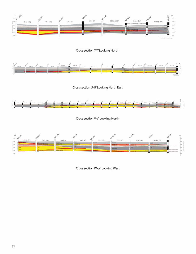
31
2.29m (7.5') of 0.05% @102.1m (335.0')2.59m (8.5') of 0.03% @104.4m (342.5') [between tails]
0.76m (2.5') of 0.08% @108.1m (354.5')
1.68m (5.5) of 0.72% @102.4m (336.0')
Medium - Fine(sand)
Very coarse - Medium Pebbly(sand & gravel)
0.76m (2.5') of 0.05% @102.9m (337.5')
Sand
Mudstone ?
Sand
Thick, high gamma
Gamma peak
Sand
Gamma peak
Double peaked gamma
Sand
Mudstone
Sand
Fine(sand)
Coarse(sand)
Gamma peak
Gamma peak
Mudstone
Sand
Silt
Sand
Mudstone
Gamma peakDouble peaked gamma
Very coarse - Medium(sand)
Muddy sand
Medium - Finegrading to
Very coarse - Medium(sand)
0.91m (3.0') of 0.08% @100.8m (330.5')1.22m (4.0') of 1.55% @101.7m (333.5')
0.30m (1.0') of 5.89% @104.4m (342.5')
YD-561 between these holes, but no data.YD-577 between these holes, but no data)
33m (~108') 34m (~112') 17m (~56')17m (~56') 32.75m (~107') 34.5m (~113') 31.5m (~103')
1.07m (3.5') of 0.32% @107.0m (351.0')
2,050
2,060
2,070
2,080
2,090
2,100
T
Ele
vatio
n (m
eter
s ab
ove
sea
leve
l)
2,050
2,060
2,070
2,080
2,090
2,100
T'
Ele
vatio
n (m
eter
s ab
ove
sea
leve
l)
YD-1789
YD-1467
YD-728
YD-696
YD-132
YD-136
Sca
n of
gam
ma
and
res.
onl
y
Sca
n of
gam
ma
and
res.
onl
y
Sca
n of
gam
ma
and
res.
onl
y
Sca
n of
gam
ma
and
res.
onl
y
YD
-135
Muddy sand
Very coarse - Medium(sand)
Medium - Fine( muddy sand)
YD-134
Cross section T-T’ Looking North
0.15m (0.5') of 0.98% @101.8m (334.0')
Medium(silt & silty sand)
Abt crs sand locally. Medium - Pebbly (Very coarse)
(sand)Some pyr locally
Fine - (Coarse), Silty(sand)
Some pyrt locally
Very fine - (Medium)(silty sand)
Abt bleached appeearnce
Medium - Pebbly (Very coarse)(sand)
Coarse - Silty(sand)
1.22m (4.0') of 1.74% @100.8m (330.5')
0.30m (1.0') of 2.55% @108.2m (355.0')0.46m (1.5') of 0.06% @109.8m (360.0')
1.22m (4.0') of 0.62% @100.6m (330.0')0.46m (1.5') of 1.32% @101.4m (332.5')
1.07m (3.5') of 1.75% @109.3m (358.5')
Grading Medium to Coarse to Pebbly(sand)
0.30m (1.0') of 0.07% @98.5m (323.0')0.61m (2.0') of 0.41% @98.8m (324.0')
0.46m (1.5') of 0.35% @109.6m (359.5')
0.30m (1.0') of 0.59% @98.6m (323.5')
0.30m (1.0') of 0.59% @110.4m (362.0')
Coarse - Medium grading to VC to Pebbly
(sand)
0.46m (1.5') of 0.13% @100.6m (330.0')
0.30m (1.0') of 0.22% @111.0m (364.0')
Medium - Coarse(sand)
0.30m (1.0') of 0.37% @103.7m (340.0')
0.30m (1.0') of 0.43% @113.0m (370.5')
Sand coarseing downward
Mudstone
Sand
Double peaked High Gamma High Gamma peak
Mudstone
Sand
Sand
Thick High Gamma
Narrow Gamma Peak
Mudstone
Sand
Sand
Minor pyr in upper and lower parts Alt 340-350 (rusty stn, tan color, grn clay, no pyr or carb, decayed flds)
Silty sand (described as sandy mudstone)
Coarse - Fine(sand)
Very coarse - Medium(mud & sand)
Gritty to PebblyVery coarse - Medium
(sand)
1.22m (4.0') of 0.21% @97.6m (320.0')
0.46m (1.5') of 0.30% @109.8m (360.0')
Gamma spike
Gamma spike
Sand
Fine or silty sand
Mudstone
Sand (poor res signature)
Sand
Fine or muddy sand
Mudstone
Sand
Mudstone
Gamma spike
Gamma Spike
Fine - Coarse(sand)
Silty (sand)(From Res Log)
1.37m (4.5') of 0.03% @102.4m (336.0')0.30m (1.0') of 0.42% @112.7m (369.5')
Elevations of about 15', adjusted.
23.2m (~76') 23m (~75') 23m (~75') 15m (~49')91m (~299') 15.5m (~51')
46.5m (~153') 26m (~85') 20.5m (~67') 45.5m (~149') 116m (~381') 22.5m (~75') 45.5m (~149') 23.5m (~77') 23.5m (~77')YD-553, 561, 555, and 703 are between these holes,
but no data is available for them.YD-2106 is between these holes, but no data
YD-1257 is between these holes, but no data
YD-1605
YD-1461
YD-1470
YD-64YD-71
8
YD-675
YD-8
YD-76YX-11
7
YD-122
YD-120
YD-1252
YD-1255
YD-202
YD-1262
YD
-284
Sca
n of
gam
ma
and
res.
log
only
Sca
nned
log
only
. Poo
r res
.
Sca
nned
Res
. and
Gam
ma
log
only
Poo
r sam
ple
desc
riptio
ns,o
nly
min
eral
dat
a us
ed.
Sca
nned
Res
. and
Gam
ma
log
only
Poo
r sam
ple
desc
riptio
ns, n
o re
s.
Poo
r sam
ple
desc
riptio
ns, n
o re
s.
Sca
nned
Res
. and
Gam
ma
log
only
Sca
nned
Res
. and
Gam
ma
log
only
Poo
r sam
ple
desc
riptio
ns, M
iner
al n
ot re
ored
edLi
th fr
om re
s, m
in. f
rom
gam
ma
Very coarse(mud & sand)
Gamma spike
Gamma spike
Sand
Fine or silty sand
Mudstone
Sand
Very fine - Medium(mud & sand)
Fine - Coarse(sand)
2,050
2,060
2,070
2,080
2,090
2,100
U
Ele
vatio
n (m
eter
s ab
ove
sea
leve
l)
2,050
2,060
2,070
2,080
2,090
2,100
U'
Ele
vatio
n (m
eter
s ab
ove
sea
leve
l)
Cross section U-U’ Looking North East
Silt w/ clay mtx
Silt & Very fine sand.
Mudstone(decscribed as silt w/ clay mtx)
Fine - (Coarse)(sand)
Local abt pyr
Sand & Gravel Abt Pyr
Medium - Fine(sand)
Fine - Very coarse(sand)
and Pebbly
Medium(sand)
Very coarse - Medium(sand)
Fine - Coarse(sand)
Mudstone (described as silt)
Very fine - Medium(sand)silty
minor pyr 3.05m (10.0') of 0.34% @102.0m (334.5')
3.35m (11.0') of 0.64% @ 109.3m (358.5')
0.61m (2.0') of 0.08% @114.6m (376.0')
Medium - Very coarse(sand)
Medium - Coarse to Coarse-Grit
(sand)
0.61m (2.0') of 0.69% @ 100.3m (329.0')
0.46m (1.5') of 0.41% @104.9m (344.0')0.30m (1.0') of 1.99% @106.9m (350.5')
0.30m (1.0') of 0.38% @116.0m (380.5')
Coarse(sand)
Fine - Coarseand gritty
(sand)
0.46m (1.5') of 1.57% @99.5m (326.5')0.30m (1.0') of 9.27% @101.1m (331.5')0.30m (1.0') of 3.84% @102.0m (334.5')0.76m (2.5') of 2.36% @103.0m (338.0')
0.61m (2.0') of 3.71% @104.9m (344.0')
0.30m (1.0') of 0.95% @114.8m (376.5')
Fine - Medium(sand)
Fine - Very coarse and gritty
(sand)
2.13m (7.0') of 0.14% @99.1m (325.0')2.13m (7.0') of 1.12% @101.2m (332.0')
0.30m (1.0') of 0.46% @113.6m (372.5')
Very coarse(sand)
Fine - Medium(sand)
Grading to SS and Grit. Very coarse Scat Pebbles
1.22m (4.0') of 0.04% @97.6m (320.0')0.46m (1.5') of 0.85% @100.5m (329.5')
0.30m (1.0') of 0.14% @112.7m (369.5')
Fine - Coarse(sand)
Carb shale & Pyr 331.5-333'1.68m (5.5') of 0.40% @101.4m (332.5')
Fine - Very coarse(sand)
Coarse - Grit(sand)
2.44m (8.0') of 0.20% @87.8m (288.0')
1.98m (5.5') of 1.70% @101.1m (331.5')
0.91m (3.0') of 0.77% @111.7m (366.5')
Fine - Very coarse(sand)
Mudstoneslighly Carbonaceous
Fine - Medium(sand)
Fine - Medium(mud & sand)
Mudstone (sandy)
0.61m (2.0') of 0.05% @86.6m (284.0')
0.30m (1.0') of 0.43% @91.9m (301.5')
0.23m (0.75') of 1.99% @102.1m (334.8')0.30m (1.0') of 2.11% @103.0m (338.0')
0.91m (3.0') of 1.14% @112.5m (369.0')
MudstoneCarbonaceous
SAND&
SILTMedium - Granules
(sand)
Mudstoneminor pyrite
Very fine - Medium(silty sand)
Coarse - Pebbly(sand & gravel)
minor pyrite
1.83m (6.0') of 0.01% @85.7m (281.0')
0.61m (2.0') of 0.56% @90.7m (297.5')
1.52m (5.0') of 0.05% @100.9m (331.0')0.76m (2.5') of 0.37% @102.4m (336.0')
1.22m (4.0') of 0.07% @110.1m (361.0')
3.96m (13.0') of 0.02% @84.1m (276.0')
0.61m (2.0') of 0.05% @88.7m (291.0')0.46m (1.5') of 0.06% @90.9m (298.0')
0.46m (1.5') of 0.89% @102.3m (335.5')
0.91m (3.0') of 0.50% @109.9m (360.5')
Coarse(sand)
Gray to BrownClean
0.76m (2.5') of 0.19% @84.5m (277.0')
0.76m (2.5') of 0.86% @89.6m (294.0')
0.30m (1.0') of 1.53% @102.0m (334.5')
1.22m (4.0') of 1.23% @109.9m (360.5')
Mudstone(described as
Mud and Sand)
Very coarse - Gritty(sand) 0.30m (1.0') of 0.46% @89.2m (292.5')
0.23m (0.75') of 0.39% @107.7m (353.5')0.91m (3.0') of 0.10% @108.8m (357.0')1.52m (5.0') of 2.12% @109.8m (360.0')
0.30m (1.0') of 0.31% @103.8m (340.5')0.30m (1.0') of 0.98% @105.0m (344.5')
0.46m (1.5') of 2.56% @109.3m (358.5')
1.07m (3.5') of 0.04% @87.8m (288.0')
0.30m (1.0') of 0.28% @103.5m (339.5')
0.46m (1.5') of 3.07% @108.8m (357.0')
1.07m (3.5') of 0.13% @86.3m (283.0')0.46m (1.5') of 0.23% @88.9m (291.5')
0.15m (0.5') of 0.07% @108.7m (356.5')0.30m (1.0') of 0.62% @109.3m (358.5')
Very fine - Medium (F)(silt)
Very fine - (Medium)(sand)
Minor pyr
1.07m (3.5') of 0.05% @89.2m (292.5')
0.30m (1.0') of 0.25% @105.5m (346.0')0.61m (2.0') of 0.09% @105.8m (347.0')0.46m (1.5') of 0.06% @109.9m (360.5')0.30m (1.0') of 0.39% @110.4m (362.0')
Sand (not described, from res.)
Hole too shallow
Mudstone(not described)
Gamma spike
Gamma spike
Gamma spike
Gamma spike
?
Muddy Sand(described as
mudstone)
No upper tail noted Medium - Peb (Very coarce)(sand)
Locally abt PyrAlt near 365'
2,050
2,060
2,070
2,080
2,090
2,100
Ele
vatio
n (m
eter
s ab
ove
sea
leve
l)
V
2,050
2,060
2,070
2,080
2,090
2,100
Ele
vatio
n (m
eter
s ab
ove
sea
leve
l)
V'
32m (~105') 32m (~105') 35m (~115') 32m (~105') 32.5m (~107') 32.5m (~107') 33.5m (~110')30.2m (~99') 15.5m (~51') 19m (~62') 19m (~62') 13m (~43') 18m (~59')
14.5m (~48') 33.5m (~110') 32m (~105') 32m (~105') 35m (~115') 30.5m (~100') 54.5m (~179')YD-37
2
YD-165
YD-1848
YD-171 YD-32
2
YD-185
YD-199
YD-195
YD-215
YX-109c
YD-178
YD-282
YD-184
YD-314
YD-150
YD-172
YD-154
YD-175
YD-173
YD-159
YD-631
YD
-129
5Pa
pper
cop
y of
gam
ma
and
resi
stiv
ity o
nly
Very coarse - Pebbly(sand & gravel)
Medium - Gran(sand & gravel)
Local Peb.abt Very fine - Fine pyr
Medium - Gran(sand & gravel)
Local minorVery fine - Fine pyr
Min
eral
not
reco
rded
Fine - Coarse(sand)
Fine - Coarse(sand)
Very Coarse - Grit(sand)
MudstoneCarbonaceous
Coarse - Fine(mud & sand)
Very Coarse - Pebbly(sand & gravel)
Very Coarse - Medium(sand)
Coarse Pebbly(sand & gravel)
Fine(mud & sand) Medium - Fine
(mud & sand)
Very Coarse - Pebbly(sand & gravel)
Medium(sand)
Coarse Clean(sand)
Coarse - Fine(mud & sand)
Fine(mud & sand)
Very Coarse - Pebbly(sand & gravel)
Medium - Peb (Very coarce)(sand)
Silty zonessome pyr
Fine - (Coarse)(sand)abt pyr
Cross section V-V’ Looking North
YD-1294
YD-1285
YD-1284
YD-1281
YD-1280
YD-1278
a
YD-1276
Coarse - Fine(muddy sand)
Very coarse - Pebbly(sand & gravel)
1.07m (3.5') of 0.13% @86.3m (283.0')0.46m (1.5') of 0.23% @88.9m (291.5)
0.15m (0.5') of 0.07% @108.7m (356.5')0.30m (1.0') of 0.62% @109.3m (358.5')
YD-159
Fine - Coarse(sand)
Silty sand. Described as Mudstone
0.76m (2.5') of 1.0' of 88.9m (291.5')
0.30m (1.0') of 0.23% @104.3m (342.0')
0.30m (1.0') of 0.42% @110.7m (363.0')
YD-106
Coarse clean (sand)
Silty or fine (sand)
Sand
Double peaked gamma anomaly. "0.03" & "0.12" marked on log
Small Gamma spike
Gamma spike. "0.10" marked on log.
Very minor gamma spike
Coarse clean(sand)
Silty Sand
Mudstone
Silty or Fine (Sand)
Mudstone
Minor gamma spike. "0.05" marked on log.Minor gamma spike. "0.03" marked on log.
High gamma spike. # illegible.
Very minor gamma spike
Sand, sli coarser base
Sand, coarse base
High gamma spike. "0.78"? marked
Weak gamma spike
Very weak gamma spike
Gamma Spike. # illegiblieCoarse Sand
Silty Sand
Mudstone
Sand
Gamma spike. "0.17"
Gamma spike. "0.06"
Wide gamma. "0.33"
Sand, coarser base
Sand, coarse clean baseassoc. w/ mineral
Tripple peaked gamma anomaly. "0.17, 0.30, 0.15" respectively
Gamma spike. "0.08"
Wide Gamma. "3.30"
No upper gamma
Sand, coarser base
Mudstone
Silty Sand, coaresing down
Coarse clean(sand)
(between tails)
Gamma spike "0.23"Gamma spike. "0.37"
Gamma Spike. "0.14"
Double peaked gamma. "0.03 and 0.07"
Gamma spike. "0.17"
Gamma spike. "0.10"
Gamma spike. "0.04"
Gamma spike. "0.07"?Gamma spike. "0.15"
Gamma spike "0.03" marked.
46.5m (~153') 33m (~108') 83m (~272') 33m (~108') 64m (~210') 65m (~213') 24.5m (~80') 31.5m (~103')
Scan
ned
Gam
ma
and
Res
. Log
onl
y.
W
2,050
2,060
2,070
2,080
2,090
2,100
Ele
vatio
n (m
eter
s ab
ove
sea
leve
l)
W'
2,050
2,060
2,070
2,080
2,090
2,100
Ele
vatio
n (m
eter
s ab
ove
sea
leve
l)
Scan
ned
Gam
ma
and
Res
. Log
onl
y.
Scan
ned
Gam
ma
and
Res
. Log
onl
y.
Scan
ned
Gam
ma
and
Res
. Log
onl
y.
Scan
ned
Gam
ma
and
Res
. Log
onl
y.
Scan
ned
Gam
ma
and
Res
. Log
onl
y.
Scan
ned
Gam
ma
and
Res
. Log
onl
y.
Coarse clean(sand) Coarse
(sand)
Silty Sand
Silty Sand
Coarse (sand)
Coarse clean(sand)
Fine(muddy sand)
Medium - Coarse(sand)
Cross section W-W’ Looking West