Embed Size (px)
Citation preview

RADIO SCIENCE Journal of Research NBS /USNC- URSI Vol. 69D, No.9, September 1965
Directivity of Uniformly Spaced Optimum Endfire Arrays With Equal Sidelobes
M.T.Ma
Central Radio Propagation Laboratory, National Bureau of Standards, Boulder, Colo.
(Received March 5, 1965; revised April 16, 1965)
A mathe matical formulation is devised for a uniformly spaced and uniformly progressively phased antenna array of a given number of isotropic ele ments such that the final radiation pattern is end fire with no large bac klobe. The pallern also has the maximum number of sidelobes of equal level, modifying the result of an earlier paper, eve n when the ele ment spacing is made arbitrarily small. The directive gain , the fir st null beamwidth , the half·power beamwidth, the current excitations, and the required phases for s uch an array are given in c urves as a fun ction of the ele me nt spacin g. It is shown that the li miting radiation characteri s ti cs whe n the ele ment spacing approaches zero can also be de termined in a relatively simple manne r.
1. Introduction
Since the publication of Dolph's paper [1946] , many articles dealing with the optimization between the beamwidth and the sidelobe level of linear antenna arrays have appeared in the lite rature. In summary, different types of mathematical formulations have been used by different investigators for differe nt arrays, depending on whether the array is broadside or endfire, whether the total number of elements in the array is odd or e ve n, and whether the element s pacing is greater or less than one·half wavelength [Dolph, 1946; Riblet, 1947; DuHamel, 1953; Pritchard , 1955]. A unifi ed approach covering all these cases wa's des cribed by Ma and Cheng [1961a].
The proble m of maximizing the directivity of an array was inves tigated by Uzkov [1946]. He showed, by means of an orthogonal transformation in vector space, that the maximum directivity of an endfire array of n isotropic elements, as the element spacing approaches zero, is numerically equal to n2• Other techniques for improving directivities of endfire arrays were also proposed [Hansen and Woodyard, 1938; Goward, 1947]. Bloch, Medhurst and Pool [1953] investigated similar problems by using the impedance relation between the array elements, but only a very limited calculation was given in their paper. Based on their method, a rather extensive calculation of the maximum directivity of an endfire array of half· wave dipoles was made later [Stearns, 1965]. Recently, Tai made some investigation of the optimum direc· tivity of uniformly spaced broadside arrays [1964] and the ordinary e ndfire arrays [1963] of isotropic sources or dipoles. The sidelobe le vel of an array was not considered or limited in any of these papers.
As far as the directivity of an array with equal side· lobes is concerned, Reuss [1959] derived a formula for the Chebyshev linear broadside arrays consisting of infinitesimal dipoles, but hi s formula provides no information concerning the effect on the directivity
when the element spacing changes. Stegen [1960] obtained an expression for the direc tivity in terms of Chebyshev polynomials, but hi s expression is valid only when the ele ment spacing is an integral multiple of a half·wavelength. A general approach for dealing with thi s problem outlined by Ma and Cheng [1961a] was based on the idea of keeping the number of side· lobes as great as possible and with a (desired) equal level e ven when the element spacing was less than one· half wavelength. Pertine nt num erical res ults on directive gains, however, were not reported there. More recently, while attempting to obtain some nu· meri cal result, it was discovered that , according to the procedures outlined by Ma and Cheng [1961a], the sidelobes in the final radiation pattern synthesized for an odd number of elements are not all equal in level, since there always is a higher sidelobe occurring near () = 71"/2, and that the final pattern for an eve n number of elements is not physically realizable (e.g., the "power" pattern function will become negative for some physical angles). It is the purpose of thi s paper to modify the procedures given before in such a way that the final pattern will have all sidelobes at an equal level. The modified procedures given in this paper will be valid for both an odd and even number of elements.
2. Mathematical Formulation
The field from a linear array of n equispaced elements as given in fi gure 1 can be mathematically represented by the polynomial:
where
n- J E(z) = 2: akzk,
k=O
z= exp (jt/J) ,
(1)
(2)
774- 625 0 - 65- 4 1249
TO DISTANT POINT
~--+--2--------------ri-1
FIGURE 1. A Linear array of n equi-spaced isotropic elements_
(3)
and ak represents the excitation of the kth elementIn this paper ak are all real, implying that the array is uniform-progressively phased (a)_ It was previously shown [Cheng and Ma, 1960] that, by introducing a new variable, y,
one can express 1 E(z) 12 , the power pattern, as a polynominal of y,
where
1 E(z) 12 = E(z)E(z- l)
n - l
= 2: bm(zm+z- m)l z+ z- I=y ---,> • P(y), 11l= O
n- l - m
bm = '2: aiam+i, 1 ~ m ~ (n-l), i = O
(5)
(6)
(7)
Since P(y) is a polynominal of (n-l)th degree with real coefficients, and is non-negative for all physical values of y in the interval [- 2, 2], it generally can only contain a combination of the following possible elementary factors:
(i) (y+ bk) or (bk - y) with bk real and ~ 2, (ii) (y+ bk)2 with bk real and 1 bk 1 < 2,
(iii) (yZ + 2bkl y+ b%l + b%2) with bkl and bk2 real.
In particular, for arrays producing the maximum possible number (n - 1) of physical nulls in the visible range - 2 ~ y ~ 2, the only factors that can appear in P(y) are (y+ 2) and (y+ bk)2 with 1 bkl < 2. Therefore, depending on whether n is odd or even, P(y) for such an array must be:
n - l -r Po(Y) = n (y+ bk)2
k=1 for odd n, (8)
n- 2 - 2
Pe(y) = (y+ 2) n (y+ bk)2 for even n, (9) k=1
where all bk are real, distinct, and I bkl < 2. In (8) and (9), we have assumed that y= 2 is the location of the main beam. The corresponding array polynominals are, respectively,
and
n - }
2
Eo(Z) = n (l + bkz + Z2) k=1
n - 2 2
for odd n, (10)
Ee(z) = (1 + Z) n (1 + bkz + Z2) for even n_ (11) k=1
The excitation coefficients ak in (1) can then be determined by expanding (10) or (11).
With this preliminary analysis given, the general procedure of synthesizing an array having the maxi· mum number of nulls can now be summarized as fol· lows: (i) to determine bk for (8) or (9) according to a I
specification, and (ii) to determine the required ex· citation coefficients using (10) or (11).
3. Directivity of Endfire Arrays With Equal Sidelobes
For arrays having all the sidelohes equal in level, the locations of nulls (y = - bk ) and sidelobes (y = Yl) are related in a special manner, where
2 > ( - bl) > YI > ( - b2) > Y2> . . .
> YIl -3 > (- bl/- I) > (- 2) for odd n, (12) 2 2
and
2 > ( - bl ) > YI >. . . > YIl - 2 > ( - 2) for even n. (13) 2
The parameters bk in (8) or (9), the corresponding excitation coefficients ak in (1), and the location of sidelobes can be uniquely determined once a desired sidelobe level relative to the main beam or a desired first null location (- bl ) is specified. The detailed derivations and procedures are omitted here, but can be found elsewhere [Ma and Cheng, 1961b].
After a power polynomial P(y) is determined, the directivity or the directive gain of an endfire array with equal sidelobes can be calculated according to the conventional definition [Silver, 1949]:
(¥-d)P(Yll)
G= Wo ' (14)
1250
where
-'- ---- --------
() = O. If a smaller d is chosen, some portion of Po(Y) in the left-hand side of figure 2a will be invisible. It
WO=J.Yb P(y) dy, Ya V4-,r
with the limits given by
Yb = 2 cos IjJb = 2 cos (- 2; d + ex) when () = 1T
(15) is clear that there exists an element spacing d* < ~ for the ordinary endfire array such that the whole
visible region will be ended at y* = 2 cos (- 4; d*)
and that the final pattern will have a sidelobe at () = 1T (16)
Ya=2 cos ljJa=2 cos e:: d+ex) when (}=o.
Note that the polynominal P(y) can always be rearranged in terms of (4 -,r) such that the exact expression for Wo (and hence for G) will be obtained by integrating (15) term by term.
4. A Transformation When d< >- /2 To keep the discussion more specific, let us consider
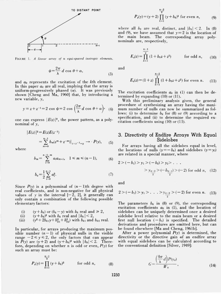
the Po(Y) given in (8). The whole pattern for d = ~ (or 2; d= 1T) is plotted as in figure 2a when the ordi
nary end fire condition, - ex = 2; d = 1T, is used. Note
that, in this case, there always is a large backlobe at () = 1T having the same magnitude as the main lobe at
z Q to W cr
'j 0=TT/2, Ijr = -TT, y=-2 <D Vi :>
L "0, ,'0, Y"
, 2TT TO= TT, Ijr =-Td+a,
, (2TT) Y = 2eos - Td+a
z o <5 w cr W .J !!? <fl
'>
L ''0,
FIGURE 2 .
(b)
'2TT ' ( 2TT Q (y') Ijr= Td+a, y =2eos Td+aJ -------- 0
Power pattern of an array with equaL sideLobes (odd n). 2" (a) Ordinary e ndfire,-a=T d = 1T',
(b) Optimum endfi re, d < d* < ~ . a =+= 0, - 0 =+= '€f d.
having the same level as the other sidelobes. In this case, no modification for improving both the di-rectivity and the beamwidth is possible if the sidelobe level remains unchanged. This actually is the case considered before by Rhodes [1953].
For d < d*, some of the sidelobes will also be invisible, then only the visible portion of the pattern would be expanded into the region O.s; () .s; 1T, making the beamwidth wider than the case when d=d*. In order to make improvement under this circumstance,
an optimum endfire condition ex =l= - 2; d, together
with a linear transformation of variables such as
(17)
is devised such that the final pattern still remains much as it formerly did up to y=y*. The parameters kl' k2 in (17), and ex can be determined by the following conditions:
y' = 2 cos (2; d+ ex) when y= 2 (() = 0),
(- 21T ) y' =2 cos -A- d+ex when y=y* (() = 1T) , (18)
y'=2 when y=-2.
The first condition of (18) maps both the magnitude and location of the main lobe, the second condition assures that the maximum possible number of sidelobes at equal level be kept and that the large backlobe be avoided, and the third condition maps the sidelobe (an odd n) or the null (an even n) originally at y=-2 to y' = 2. The transformation (17) with the conditions given in (18) is shown in figure 2b. From this figure one can see that, for d < d*, the transformation (17) always squeezes the whole pattern up to y* into the visible region and, therefore, helps to shift the pattern toward the main lobe, making the beamwidth narrower and the directivity higher. For this reason the transformed array is called the optimum endfire array. Solving (18), one obtains
ex tan-
2 2-Y2+y* 1Td ----==== tan -2+Y2+y* A '
k =- sin2 (~+ 1Tr£\ < 0 I 2 A) ' (19)
1251
-- - ---- - ----
where y* can be easily determined by the following simple relation:
n - 1 y* = 2(1- b(II+ I)/4), for n odd and -2- odd;
y* = 2(1 + y(n - I) /4), for n odd and n; 1 even, (20)
or
y* = 2 + YI - b(n-2)/2 for even n .
The phase Q' and the parameters kl and k2 required to produce an optimum endfire array can be calculated from (19) once a d < d* is chosen. From the first equation of (19) it can be concluded that Q' is always located somewhere in the first quadrant in order to make a pattern of an endfire array optimum when d< d*. Note that (19) also holds true when d=d*
d . ld ' 2'lT d'" 0 Th b an Yle s Q'''='lT--;: + >. ere seems to e a
phase di scontinuity of ('IT) as compared with the phase required by the ordinary endfire condition. This ex tra phase of '1T is actually taken care of by the fact that kl = - 1 and k2 = 0 for the case of d = d*. Of course, thi s apparent di screpancy can be removed if one tri es to map y= - 2 onto y' = - 2 , re placing the third con· dition in (18). While thi s altern ative transformation see ms more natural , as far as the Ii miting case d ~ d* is concerned , it will c reate a little mathematical diffi· c ulty in dealing with the limiting case to the othe r e nd (d~ 0) , as compared to what we have done [see (30) through (32)] by using the present approach. In any case, these two approaches yield the same array de · pending on whe ther one lik es to have the final exc itation coe ffi cients ak alternating signs (as is clearly shown in fi g. 6) or to have the sign reversal absorbed in Q' if using the alterna tive transformation s ugges ted above. As pointed out before, it is not necessary to make further modifi cation in phases for the endfire arrays with equal sidelobes whe n d= d* (considered by Rhodes [1953]) because the ordinary endfire condition for phase still holds for that parti c ular situation. Also , since thi s pape r is to primarily deal with cases when d < d*, the aforementioned two alternative approaches would not make any differe nce as far as the presentation is concerned.
The optimization discussed above specifically for Po(Y) applies as well to Pe(y) given in (9).
From (17) one has
(21)
Substituting (21) into (8) and (9), the power polynomial becomes , respectively,
n- I -y
Qo(y') = k1(n- 1) I1 (y' + b~)2 for odd n, k = 1
(22)
n- 2 2-
Qe(Y' ) = k1(n- I)(y' - 2) I1 (y' + b~)2
where
k= 1
n-2 2 -
= I k1(n-!) 1(2 - y') I1 (y' + b~,)2 for even n, k=1 (23)
(24)
Note that the second form of (23) is due to the fact that kl < 0, see (19), and k1(n- 1) < 0 for an even n. It is then clear from this second form that Qe(y') ~ 0 for - 2 :%; y' :%; 2, as it should be for a realizable power polynomial. Based on (22) and (23), the corresponding array polynomial becom es, respectively,
11- 1 2 -
E~(z) = Vk1(n- l ) I1 (1 + b{.z + Z2) for odd n, k = 1
n- 2 (25) 2 -
E'(z) = vi k1(n- l)1 (1 - z) I1 (1 + b~z+ Z2) for e ven n. k=1
(26)
A new set of exc itation coefficients required for synthe· sizing the optimum endfire array can be de termined by expanding (25) or (26).
The directivity G', the first null beamwidth (201) ,
and the half-power beamwidth (20,,) can be calculated respectively from
(27)
(28)
and
y;, = 2 cos (2; d cos 0" + Q'), (29)
where
W' = lYb Q(y') d' o V y,
Y(j 4-y'2
y~=2 cos (_2; d+Q'),
y~=2 cos C; d+ Q'),
and y;' is determined by
1252
30
G' 20
10
21T d A
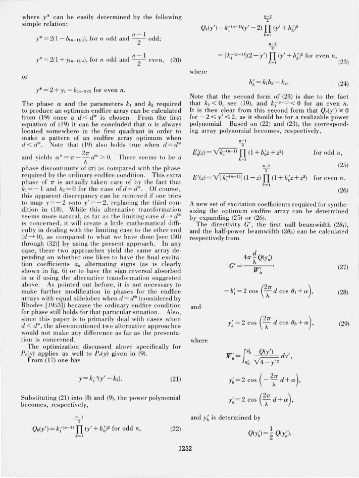
FI GURE 3. Directivities for optimum endfire arrays with equal sidelobes (- 20 dB).
Numerical res ults for n = 3 through n = 7 and for a sidelobe le vel 20 dB down from the main lobe , obtained by using these formulas are given in figu~es 3, 4, 5, 6, and 7. For comparison, the c.orrespondIng direc tivities for various d , if the ordInary endfire
2w . hi. condition - 0'=- d IS used throug out, are a so In-A
cluded in figure 3 as the dashed curves. The points mark ed with * on these dashed curves are those when d = d*.
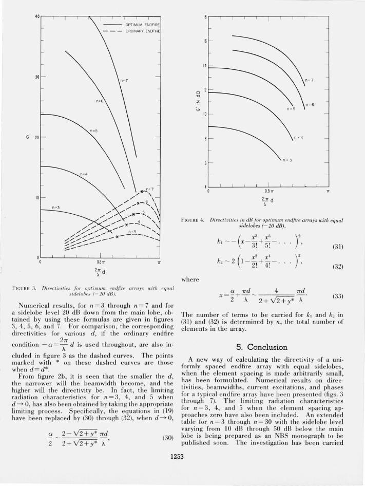
From figure 2b, it is seen that the smaller the d, the narrower will the beam width become, and the higher will the directivity be. In fact, the limiting radiation charac teristics for n = 3, 4, and 5 when d ~ 0 has also been obtained by taking th e appropriate limiti~g process. Specifically, the equations in (19) have been re placed by (30) through (32), when d ~ 0,
a 2 - v'2+Y* wd
2 2+Y2+y* A' (30)
16 r----r--,---,--,---,- ,---,-,----,-,
16
14 ~ __ _
10
n ~ 3
4L--L~ __ ~~~~-L~L-~~~ o 0.5 1T
21T d A
FIG URE 4 . Directivities in dB for optimum endjire arrays with equal sidelobes (- 20 dB).
(31)
(32)
where
0' wd 4 wd x= -+-- - --. 2 A 2+Y2+y* A
(33)
The number of terms to be carried for k, and k2 in (31) and (32) is determined by n, the total number of elements in the array.
5. Conclusion
A new way of calculating the directivity of a uniformly spaced end fire array with equal ~idelob es, when the element spacing is made arbitranly small, has been formulated. Numerical r esults on directivities, beamwidths, c urrent excitations, and phases for a typical end fire array have bee.n presented ( ~gs: 3 through 7). The limiting radiatIOn characten s tIcs for n = 3, 4, and 5 when the element spacing approaches zero have also been included. An exte nded table for n = 3 through n = 30 with the sidelobe level varying from 10 dB through 50 dB below the main lobe is being prepared as an NBS monograph to .be published soon. The inves tigation has been carned
1253
Vl w w Cl:: l? W 0
~
~ co
150
100
50
n~6
n=3 ___ ~ -- / /
/ I ./
,/
n=4 __ ----.,.;' ----/1 /
/ / I ,/'/ / /
n_~5 ____ ---""'" // / ./ /
---...-/ ,/ n=6--- ...-"""""" n=7------ .......
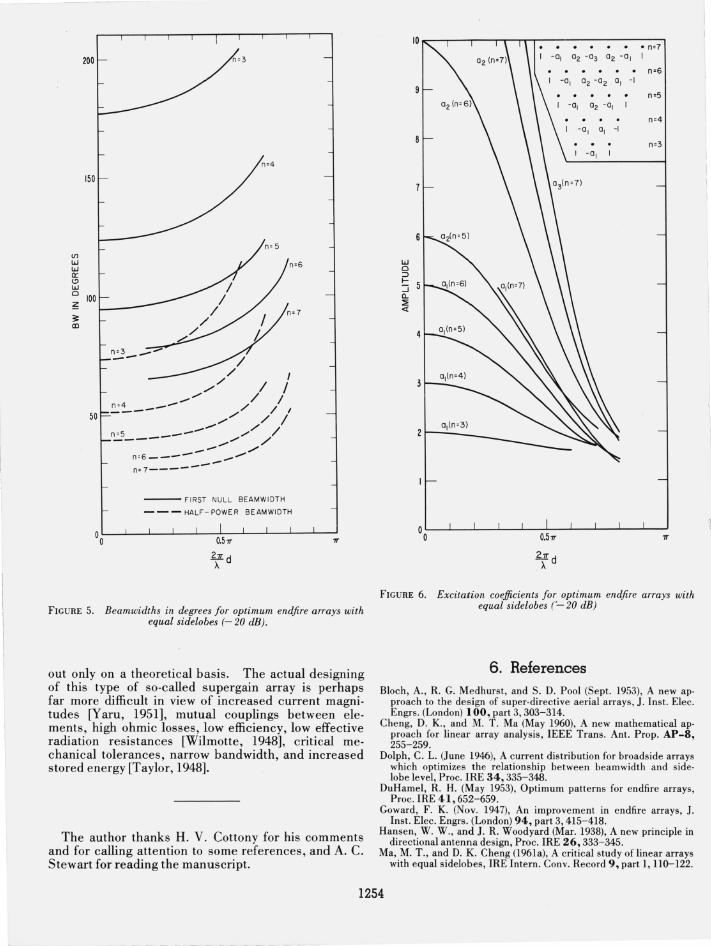
--- FIRST NULL BEAMWIDTH
---HALF-POWER BEAMWIDTH
°OL---L--J---~--L--70.75~--~--L-~--~--~~
lld A
FIGURE 5. Beamwidths in degrees for optimum end fire arrays with equal sidelobes (- 20 dB).
out only on a theoretical basis. The actual designing of this type of so·called supergain array is perhaps far more difficult in view of increased current magni· tudes [Yaru, 1951], mutual couplings between elements, high ohmic losses, low efficiency, low effective radiation resistances [Wilmotte, 1948], critical mechanical tolerances, narrow bandwidth, and increased stored energy [Taylor, 1948]_
The author thanks H. V. Cottony for his comments and for calling attention to some references, and A. C. Stewart for reading the manuscript.
10 ...-----,---r-----r-.-""l"T.--------.-n-:~7:1
02 -03 02 -01 1
1 -0, 02 -02 0, -I
1 -01 02 -0,
1 -0, 01 -I
w 0 :::> f-:::::i 0.. ::;: «
FIGURE 6. Excitation coefficients for optimum endfire arrays with equal sidelobes ('- 20 dB)
6. References Bloch, A., R. G. Medhurst, and S. D. Pool (Sept. 1953), A new ap
proach to the design of super·directive aerial arrays, J. Inst. Elec. Engrs. (London) 100, part 3, 303-314.
Cheng, D. K., and M. T. Ma (May 1960), A new mathematical ap· proach for linear array analysis, IEEE Trans. Ant. Prop. AP-8, 255-259.
Dolph, C. L. (June 1946), A current distribution for broadside arrays which optimizes the relationship between beamwidth and side· lobe level, Proc. IRE 34,335-348.
DuHamel, R. H. (May 1953), Optimum patterns for endfire arrays, Proc. IRE 41,652-659.
Goward, F. K. (Nov. 1947), An improvement in endfire arrays, J. Inst. Elec. Engrs. (London) 94, part 3, 415-418.
Hansen, W. W., and J. R. Woodyard (Mar. 1938), A new principle in directional antenna design, Proc. IRE 26,333-345.
Ma, M. T., and D. K. Cheng (1961a), A critical study of linear arrays with equal sidelobes, IRE Intern. Conv. Record 9, part I, llD-122.
1254
"0 o
<;
1.0
0.5
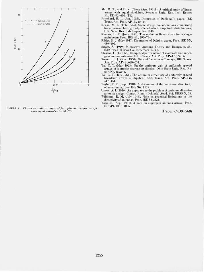
------...--- CALCU LAT ED
---- ANTICIPATED
~d A
7T
FIGURE 7. Phases in radians required for optimum end fire arrays with equal sidelobes (-20 dB).
Ma, M. T., and D. K. Cheng (Apr. 1961b), A critical study of linear arrays with equal sidelobes, Syracuse Univ. Res. Inst. Report No. EE492- 6104 Tl2.
Pritc hard, R. L. (Jan. 1955), Di scuss ion of DuHamel's pape r, IRE Trans. Ant. Prop. AP-3, 40- 43.
Reuss, M. L. (Feb. 1959), Some design considerations concerning linear arrays having Dolph-Tchebysheff amplitude distributions, U.S. Naval Res. Lab . Report No. 5240.
Rhodes, D. R. (June 1953), The optimum linear array for a single main beam, Proc. IRE 41, 793-794.
Riblet, H. J. (May 1947), Discussion of Dolph's paper, Proc. IRE 35, 489-492.
Silver, S. (1949), Microwave Antenna Theory and Design, p. 581 (McGraw-Hill Book Co., New York, N.Y.).
Stearns, C. O. (1965), Computed performance of moderate size supergain endfire antennas, IEEE Trans. Ant. Prop. AP-13; No.6.
Stegen, R. J. (Nov. 1960), Gain of Tchebysheff arrays, IRE Trans. Ant. Prop. AP-8, 629-63l.
Tai, C. T. (Mar. 1963), On the optimum gain of uniformly spaced arrays of isotropic sources or dipoles, Ohio State Univ. Res. Report No. 1522-l.
Tai, C. T. (July 1964), The optimum direc tivity of uniformly spaced broadside arrays of dipoles , IEEE Trans. Ant. Prop. AP-12, 447- 454.
Taylor, T. T. (Sept. 1948), A discuss ion of the maximum directivity of an antenna, Proc. IRE 36, 1135.
Uzkov, A. I. (1946), An approach to the problem of optimum directive antenna des ign , Compt. Rend. (Doklady) Acad. Sci. URSS 3, 35.
Wilmotte, R. M. (July 1948), Note on practical limitations in the directivity of antennas, Proc. IRE 36, 878.
Yaru , N. (Sept. 1951), A note on supergain antenna arrays, Proc. IRE 39, 1081- 1085.
(Paper 69D9-560)
1255

![Fling StepForward Directivity (BRBF)confnews.um.ac.ir/images/41/conferences/5ncce/1399.pdf · Fling StepForward Directivity Forward Directivity . [] g Forward Directivity Fling Step[]](https://img.dokumen.tips/doc/110x75/5ead3a2bf150643e9064f1eb/fling-stepforward-directivity-brbf-fling-stepforward-directivity-forward-directivity.jpg)