Embed Size (px)
Citation preview

DIRECT TORQUE CONTROL OF INDUCTION MACHINESUTILIZING MULTILEVEL INVERTER AND ARTIFICIAL
INTELLIGENT
ALI MORTEZAEI
A project report submitted in partial fulfilment of
the requirements for the award of the degree of
Master of Engineering (Electrical-Power)
Faculty of Electrical Engineering
Universiti Teknologi Malaysia
DECEMBER 2010

iii
Special dedicated to my beloved father, mother & family

iv
AKNOWLEDGEMENT
I would like to take this opportunity to thank various people who have provided much
assistance and invaluable information to make this project a success. First of all I would like
to express my sincere gratitude and appreciation to my supervisor, Dr Naziha bt. Ahmad Azli
for her valuable supervision and generous encouragement throughout the project duration.
I am also indebted to Associate Professor Dr Nik Rumzi b. Nik Idris for his significant
guidance and great support during the research.
I also wish to express my gratitude to people who have contributed to this thesis. In
particular, the members of academic and technical staff of the Energy Conversion
Department, Universiti Teknologi Malaysia for the discussions and technical help. And not
forgetting those whom have either directly or indirectly helped me in this project.
Last but not least, I own many thanks to my family and my friends for their loves,
encouragement and moral support.
v
ABSTRACT
This thesis presents a high performance Direct Torque Control (DTC) of induction
machine (IM) drives. A summary of the theoretical aspects and principles of DTC are given
with emphasis on two major problems, i.e. high torque ripple and variable switching
frequency. In order to solve these problems, this thesis proposed direct torque control of
induction machines utilizing multilevel inverter and artificial intelligent. It proposes to use
three, five and seven level cascaded and diode clamped inverter topology which results in
further torque ripple minimization compare to the two level inverter-based conventional DTC.
It also proposed a new Fuzzy DTC using Sugeno as the inference method to replace the
hysteresis comparators in the conventional DTC, which results in reducing the flux ripples
significantly as well as reducing the Total Harmonic Distortion (THD) of the phase current
since a more sinusoidal current wave is achieved by solving the problem of variable switching
frequency. The simulation of the multilevel inverter topology-based Conventional and Fuzzy
DTC is presented. The simulation results prove that torque ripple reduction is obtained while
the stator flux ripples also manage to achieve reduction. Furthermore, the switching frequency
is fixed and a smoother sinusoidal phase current is obtained.

vi
ABSTRAK
Tesis ini menyampaikan kaedah pelaksanaan pemacu Kawalan Daya Kilas
Terus (DTC) dari mesin aruhan . Ringkasan tentang teori dan prinsip-prinsip DTC
telah diberikan penekanan pada dua masalah utama, iaitu riak daya kilas yang besar
dan frekuensi pensuisan yang berubah. Tesis ini telah memperkenalkan DTC dari
mesin aruhan dengan menggunakan inverter yang mempunyai multi-tahap dan teknik
(artificial intelligent). Ia menggunakan tiga, lima dan tujuh tahap inverter yang
disambungkan secara bersiri dan (topologi inverter yang dijepit oleh diod). Ini akan
mengurangkan riak tork yang selebihnya berbanding dengan inverter dua tahap yang
berasakan konvensional konsep. Ia juga memperkenalkan Fuzzy DTC yang baru
dengan menggunakan Sugeno sebagai kaedah inferensi untuk menggantikan
pembanding histerisis bagi konvensional DTC. Ini akan mengurangkan riak flux
secara berkesan, ia juga mengurangkan THD bagi arus fasa, kerana gelombang arus
sinus dapat dicapai dengan mengatasi masalah frekuensi pensuisan yang berubah.
(Simulasi) bagi inverter multi-tahap yang berasakan konvensional konsep dan Fuzzy
DTC akan dipersembahkan. Keputusan simulasi telah mengesahkan bahawa
pengurangan riak tork telah diperolehi dan riak fluks stator juga dapat dikurangkan.
Di samping itu, frekuensi pensuisan telah ditetapkan dan fasa arus sinus yang lebih
baik dapat diperolehi.

vii
TABLE OF CONTENTS
CHAPTER TITLE PAGE
TITLE PAGE i
DECLARATION ii
DEDICATION iii
ACKNOWLEDGEMENT iv
ABSTRACT v
ABSTRAK vi
CONTENTS vii
LIST OF TABLES xiii
LIST OF FIGURES xiv
LIST OF SYMBOLS xx
1 INTRODUCTION 1
1.1 A Look Back On Electrical Machine Drives 1
1.2 Direct Torque Control (DTC) 3
1.2.1 The Conventional DTC 4
1.2.2 The Evolution of DTC 5

viii
1.3 Thesis Objective and Contributions 7
1.4 Methodology of Research 7
1.5 Thesis Organizations 8
2 LITERATURE REVIEW OF DTC 9
2.1 Introduction 9
2.2 Modeling of Induction Machine 9
2.3 Principle of DTC 14
2.3.1 3-phase Voltage Source Inverter (VSI) 14
2.3.2 Direct Flux Control 16
2.3.3 Direct Torque Control 18
2.3.4 Switching Selection 22
2.3.5 Stator Flux Estimation 23
2.3.5.1 Stator Voltage Model 23
2.3.5.2 Current Model 24
2.3.6 Hysteresis Controller 25
2.3.6.1 Switching Frequency 25
2.3.6.2 Torque Ripple 27
2.3.6.3 Current Harmonics 29

ix
2.4 Chapter Conclusions 30
3 PRINCIPLES AND SIMULATION OF THE MULTILEVEL INVERTER-BASED CONVENTIONAL AND FUZZY DTC 31
3.1 Introduction 31
3.2 Conventional DTC 31
3.2.1 2-level inverter-based conventional DTC 34
3.2.2 Multilevel inverter-based conventional DTC 39
3.2.3 3-level inverter-based conventional DTC 40
3.2.3.1 3-level cascaded inverter-based conventional DTC 41
3.2.3.2 3-level diode clamped inverter-based conventional
DTC
45
3.2.4 5-level inverter-based conventional DTC 49
3.2.4.1 5-level cascaded inverter-based conventional DTC 50
3.2.4.2 5-level diode clamped inverter-based conventional
DTC
54
3.2.5 7-level inverter-based conventional DTC 58
3.2.5.1 7-level cascaded inverter-based conventional DTC 59
3.3 Fuzzy DTC 63
3.3.1 2-level inverter-based fuzzy DTC 65
x
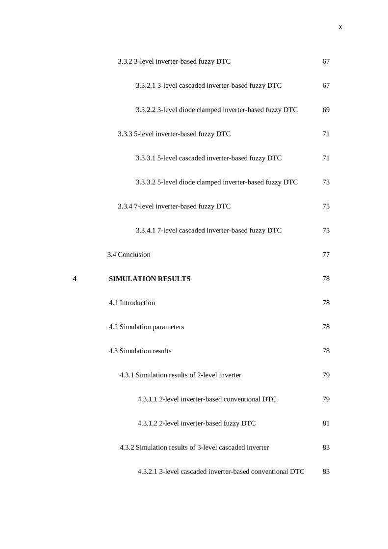
3.3.2 3-level inverter-based fuzzy DTC 67
3.3.2.1 3-level cascaded inverter-based fuzzy DTC 67
3.3.2.2 3-level diode clamped inverter-based fuzzy DTC 69
3.3.3 5-level inverter-based fuzzy DTC 71
3.3.3.1 5-level cascaded inverter-based fuzzy DTC 71
3.3.3.2 5-level diode clamped inverter-based fuzzy DTC 73
3.3.4 7-level inverter-based fuzzy DTC 75
3.3.4.1 7-level cascaded inverter-based fuzzy DTC 75
3.4 Conclusion 77
4 SIMULATION RESULTS 78
4.1 Introduction 78
4.2 Simulation parameters 78
4.3 Simulation results 78
4.3.1 Simulation results of 2-level inverter 79
4.3.1.1 2-level inverter-based conventional DTC 79
4.3.1.2 2-level inverter-based fuzzy DTC 81
4.3.2 Simulation results of 3-level cascaded inverter 83
4.3.2.1 3-level cascaded inverter-based conventional DTC 83

xi
4.3.2.2 3-level cascaded inverter-based fuzzy DTC 85
4.3.3 Simulation results of 3-level diode clamped inverter 87
4.3.3.1 3-level diode clamped inverter-based conventional
DTC 87
4.3.3.2 3-level diode clamped inverter-based fuzzy DTC 89
4.3.4 Simulation results of 5-level cascaded inverter 91
4.3.4.1 5-level cascaded inverter-based conventional DTC 91
4.3.4.2 5-level cascaded inverter-based fuzzy DTC 93
4.3.5 simulation results of 5-level diode clamped inverter 95
4.3.5.1 5-level diode clamped inverter-based conventional
DTC 95
4.3.5.2 5-level diode clamped inverter-based fuzzy DTC 97
4.3.6 Simulation results of 7-level cascaded inverter 99
4.3.6.1 7-level cascaded inverter-based conventional DTC 99
4.3.6.2 7-level cascaded inverter-based fuzzy DTC 101
4.4 Conclusion 103
5 CONCLUSIONS AND FUTURE WORK 104
5.1 Conclusions 104

xii
5.2 Future Work 105
REFERENCES 106

xiii
LIST OF TABLE
TABLE NO. TITLE PAGE
2.1 The variation of θsr with different voltage vector 19
2.2 Voltage vector selection table 23
3.1 Voltage vector selection table in 2-level inverter-based conventional
DTC 38
3.2 Voltage vector selection table in 3-level cascaded inverter-based
conventional DTC 44
3.3 Voltage vector selection table in 3-level diode clamped inverter-based
conventional DTC 48
3.4 Voltage vector selection table in 5-level cascaded inverter-based
conventional DTC 53
3.5 Voltage vector selection table in 5-level diode clamped inverter-based
conventional DTC 57
3.6 Voltage vector selection table in 7-level cascaded inverter-based
conventional DTC 62
4.1 Simulation parameters of DTC 78

xiv
LIST OF FIGURE
FIGURE NO. TITLE PAGE
1.1 Classification of induction machines control methods 2
1.2 Conventional DTC drive configuration 4
2.1 Cross-section of an elementary symmetrical three-phase machine 10
2.2 Dynamic d-q equivalent circuits of an induction machine (a) d-axis
circuit, (b) q-axis circuit 13
2.3 Schematic diagram of VSI 15
2.4 Voltage space vector 15
2.5 Six equally sectors with different set of voltage vector 16
2.6 Voltage vectors selection to control the stator flux locus within its
hysteresis band 17
2.7 Block diagram of the stator flux hysteresis comparator 17
2.8 Typical waveforms quoted from [29] 18
2.9 The variation of θsr with application of (a) active, (b) reverse active or
zero voltage vector, (c) radial voltage vector 19

xv
2.10 3-level torque hysteresis comparator 20
2.11 Four-quadrant operation 20
2.12 Typical waveforms of the torque, torque error, and torque error status 21
2.13 Optimum switching voltage vector in Sector II for shaft rotation (a)
counter-clockwise, (b) clockwise 22
2.14 Unpredictable switching frequency for (a) low speed, (b) high speed 26
2.15 Occurrence of overshoot and undershoot 27
2.16 Two trajectories of torque with (a) large sampling time, (b) small
sampling time 28
3.1 Simulation scheme conventional DTC 32
3.2 Flux estimator based on stator voltage 33
3.3 Torque estimator 33
3.4 Voltage Space vector diagram of 2-level inverter 34
3.5 Simulation scheme of 2-level inverter 34
3.6 Simulation scheme of sector selector in 2-level inverter-based
conventional DTC 35
3.7 3-level hysteresis controllers to minimize the torque error 36
3.8 Simulation scheme of voltage vector selector of 2-level inverter-based
conventional DTC 37

xvi
3.9 Simulation scheme of sector selector in multilevel inverter-based
conventional DTC 39
3.10 Voltage space vector diagram of 3-level inverter 40
3.11 Simulation scheme of 3-level cascaded inverter 41
3.12 7-level hysteresis controllers to minimize the torque error 42
3.13Simulation scheme of voltage vector selector of 3-level cascaded
inverter-based conventional DTC 43
3.14 Simulation scheme for three level diode clamped inverter 45
3.15 5-level hysteresis controllers to minimize the torque error 46
3.16 Simulation scheme of voltage vector selector of 3-level diode clamped
inverter-based conventional DTC 47
3.17 Voltage space vector diagram of 5-level inverter 49
3.18 Simulation scheme of 5-level cascaded inverter 50
3.19 11-level hysteresis controllers to minimize the torque error 51
3.20 Simulation scheme of voltage vector selector of 5-level cascaded
inverter-based conventional DTC 52
3.21 Simulation scheme of 5-level diode clamped inverter 54
3.22 7-level hysteresis controllers to minimize the torque error 55
3.23 Simulation scheme of voltage vector selector of 5-level diode clamped
inverter-based conventional DTC 56

xvii
3.24 Voltage space vector diagram of 7-level inverter 58
3.25 Simulation scheme of 7-level cascaded inverter 59
3.26 15-level hysteresis controllers to control the torque error 60
3.27 Simulation scheme of voltage vector selector of 7-level cascaded
inverter-based conventional DTC 61
3.28 Simulation scheme of fuzzy DTC 63
3.29 Fuzzy logic controller inputs and output 64
3.30 Membership functions of 2-level inverter-based fuzzy DTC 65
3.31 Simulation scheme of voltage vector selector of 2-level inverter-based
fuzzy DTC 66
3.32 Membership functions of 3-level cascaded inverter-based fuzzy DTC 67
3.33 Simulation scheme of voltage vector selector of 3-level cascaded
inverter-based fuzzy DTC 68
3.34 Membership functions of 3-level diode clamped inverter-based fuzzy
DTC 69
3.35 Simulation scheme of voltage vector selector of 3-level diode clamped
inverter-based fuzzy DTC 70
3.36 Membership functions of 5-level cascaded inverter-based fuzzy DTC 71
3.37 Simulation scheme of voltage vector selector of 5-level cascaded
inverter-based fuzzy DTC 72

xviii
3.38 Membership functions of 3-level diode clamped inverter-based fuzzy
DTC 73
3.39Simulation scheme of voltage vector selector of 5-level diode clamped
inverter-based conventional DTC 74
3.40 Membership functions of 7-level cascaded inverter-based fuzzy DTC 75
3.41 Simulation scheme of voltage vector selector of 7-level cascaded
inverter-based conventional DTC 76
4.1 Simulation results of 2-level inverter-based conventional DTC (a)
Torque-Speed (b) Flux-Current (c) Torque-Flux-Current 80
4.2 Simulation results of 2-level inverter-based fuzzy DTC (a) Torque-
Speed (b) Flux-Current (c) Torque-Flux-Current 82
4.3 Simulation results of 3-level cascaded inverter-based conventional
DTC (a) Torque-Speed (b) Flux-Current (c) Torque-Flux-Current 84
4.4 Simulation results of 3-level cascaded inverter-based fuzzy DTC (a)
Torque-Speed (b) Flux-Current (c) Torque-Flux-Current 86
4.5 Simulation results of 3-level diode clamped inverter-based
conventional DTC (a) Torque-Speed (b) Flux-Current (c) Torque-Flux-
Current 88
4.6Simulation results of 3-level diode clamped inverter-based fuzzy DTC
(a) Torque-Speed (b) Flux-Current (c) Torque-Flux-Current 90
4.7 Simulation results of 5-level cascaded inverter-based conventional
DTC (a) Torque-Speed (b) Flux-Current (c) Torque-Flux-Current 92

xix
4.8 Simulation results of 5-level cascaded inverter-based conventional
DTC (a) Torque-Speed (b) Flux-Current (c) Torque-Flux-Current 94
4.9 Simulation results of 5-level diode clamped inverter-based
conventional DTC (a) Torque-Speed (b) Flux-Current (c) Torque-Flux-
Current 96
4.10 Simulation results of 5-level diode clamped inverter-based fuzzy DTC
(a) Torque-Speed (b) Flux-Current (c) Torque-Flux-Current 98
4.11 Simulation results of 7-level cascaded inverter-based conventional
DTC (a) Torque-Speed (b) Flux-Current (c) Torque-Flux-Current 100
4.12 Simulation results of 7-level cascaded inverter-based fuzzy DTC (a)
Torque-Speed (b) Flux-Current (c) Torque-Flux-Current 102

xx
LIST OF SYMBOLS
ids ,iqs ---- d and q components of the stator current in stationary reference frame
idr ,iqr ---- d and q components of the rotor current in stationary reference frame
Lm --- Mutual inductance
Ls, Lr --- Stator and Rotor self-inductance
Mmf --- magneto-motive force
P --- No. of poles
Rs, Rr ---- Stator and rotor resistance
r.m.s. --- Root mean squared
Rpm --- Revolutions per minute
Sa,Sb,Sc ---- Switching states of phase a, b, c.
SVM --- Space Vector Modulation
Te ---- Electromagnetic torque

xxi
Terror -- Torque error
THD -- Total Harmonic Distortion
Va, Vb, Vc --- line to neutral voltage of phase a, b, c.
Vdc -- DC link voltage
VSI -- Voltage Source Inverter

CHAPTER 1
INTRODUCTION
1.1 A Look Back On Electrical Machine Drives
DC machines have been used extensively in variable speed drive over
the past decades mainly because of the decoupled control of flux and torque
that could be achieved by the field and armature current control respectively.
They are mostly used in variable speed applications to give a fast and good
dynamic torque response because the commutator maintains a fixed (and
nearly ideal) torque angle at all times. However, DC machines have two
major weaknesses, the mechanical commutator and brush assembly. These
make periodical maintenance a must and limit the use of DC machines in
explosive environment.
Induction machines have several advantages over DC machines. They
are robust, require less maintenance, cheaper, and operate at higher speed.
Basically, induction machines control methods can be classified into scalar
and vector control. In scalar control, only magnitude and frequency of voltage,
current, and flux linkage space vectors are controlled. Whereas, in vector
control, the instantaneous positions as well as the magnitude and frequency of
voltage, current, and flux linkage space vectors are controlled. A chart
showing the hierarchy of variable frequency control of induction machine is
given in Figure 1.1. Constant volt per hertz is a well-known scalar control

2
method while Field Oriented Control (FOC) and Direct Torque Control (DTC)
are the two most popular vector control methods.
The invention of Field-Oriented Control (FOC) in early 1970 by
F.Blaschke enables rugged induction machines to be controlled similar to that
of DC machines [1]. The advent of fast microprocessors and DSPs make the
vector control popular in the 1980’s. It is believed that the AC machines are
supplanting the DC machines in the near future [2].
FOC provides similar decoupled control of torque and flux, which is
inherently possible in the DC machines. The motor input currents are adjusted
to set a specific angle between fluxes produced in the rotor and stator
windings. The rotor flux position angle with respect to the stator must be
known in this control method. Once the flux angle is known, an algorithm
Figure 1.1: Classification of induction machines control methods

3
performs the transformation by changing three-phase stator currents into the
orthogonal torque and flux producing components [2]. These components are
controlled in their d-q axis and an inverse transformation is used to determine
the necessary three-phase currents or voltages.
Although the FOC enables an induction machine to attain fast torque
response, some problems still exist. An accurate flux estimator has to be
employed to ensure the estimated value used in calculation does not deviate
from the actual value. Besides, the coordinate transformation has increased
the complexity of this control method. In [3], it is highlighted that the inverter
switching frequency, torque ripple, and harmonic losses of the machine
increase in the steady-state operation if the hysteresis-based current-
controlled inverter is used.
1.2 Direct Torque Control (DTC)
Direct Torque Control was first introduced by Takahashi in 1986. The
principle is based on limit cycle control and it enables both quick torque
response and efficiency operation [3]. DTC controls the torque and speed of
the motor, which is directly based on the electromagnetic state of the motor
[4]. It has many advantages compared to FOC, such as less machine
parameter dependence, simpler implementation and quicker dynamic torque
response [5]. It only needs to know the stator resistance and terminal
quantities (v and i) in order to perform the stator flux and torque estimations.
The configuration of DTC is simpler than the FOC system due to the absence
of frame transformer, current controlled inverter and position encoder, which
4
introduces delays and requires mechanical transducer [6]. In [3], Takahashi
has proved the feasibility of DTC compared to FOC.
In 1996, ABB has introduced the first industrial, speed-sensorless DTC
induction motor drive. This simple control scheme has gained popularity and
it is believed that they will soon replace the vector control drives commonly
found in industry applications [7].
1.2.1 The Conventional DTC
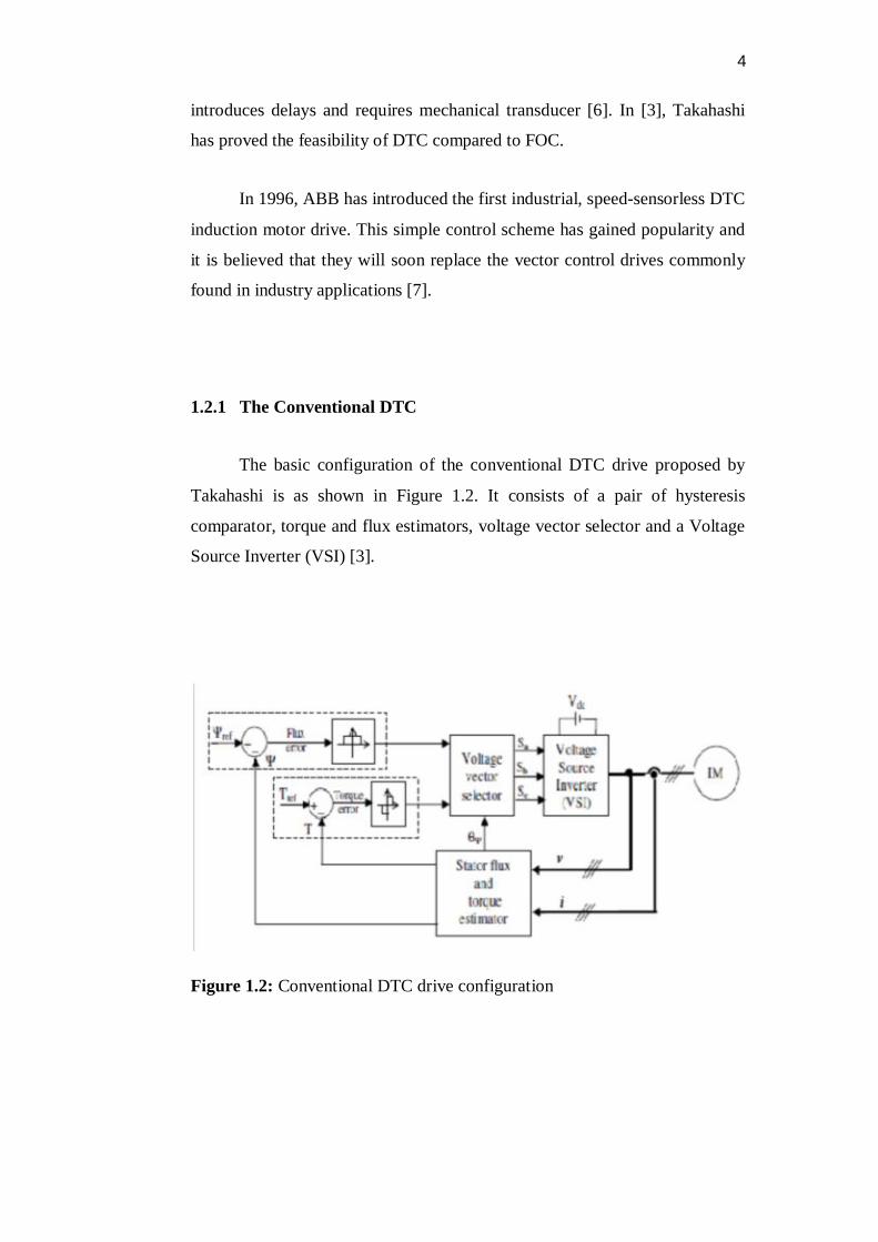
The basic configuration of the conventional DTC drive proposed by
Takahashi is as shown in Figure 1.2. It consists of a pair of hysteresis
comparator, torque and flux estimators, voltage vector selector and a Voltage
Source Inverter (VSI) [3].
Figure 1.2: Conventional DTC drive configuration

5
DTC performs separate control of the stator flux and torque, which is also
known as decouple control. The core of this control method is to minimize the
torque and flux errors to zero by using a pair of hysteresis comparators. The
hysteresis comparators lie at the heart of DTC scheme not only to determine
the appropriate voltage vector selection but also the period of the voltage
vector selected. The performance of the system is directly dependent on the
estimation of stator flux and torque. Inaccurate estimations will result in an
incorrect voltage vector selection.
The basic method for estimating the stator flux is by using the stator
voltage model. This model does not require rotor speed and only need a
single machine parameter, i.e. the stator resistance. However, noise in voltage
measurement and integration drift can pose significant problems at low speed
[8]. Another method for estimating the stator flux is named current model. It
solves the low speed problem but it needs to monitor the rotor speed. In other
words, it requires additional speed sensor or observer. In [3], a combination
of these 2 models had been proposed by using a simple lag network.
1.2.2 The Evolution of DTC
Although DTC is gaining its popularity, there are some drawbacks,
which need to be rectified. Variable switching frequency and high torque and
flux ripples are the two major problems, which draw full attention of most
researchers. To overcome these problems, extensive research and development
has been carried out.
In order to maintain the flux and torque error within the fixed
hysteresis bands, the switching frequency becomes unpredictable. It is

6
highlighted in [9] and [10] that the switching frequency varies with the
operating speed, load condition and parameters of the induction machine.
Hence, in order to ensure that the switching frequency does not exceed the
limit, we have to calculate the extreme cases corresponding to the maximum
switching frequency. Nevertheless the drive does not operate at these extreme
cases in most of the time; therefore the maximum switching frequency
capability is not fully utilized.
In order to overcome this problem, a number of methods had been
proposed in the literature. Basically these can be divided into hysteresis based
and non-hysteresis based solutions. In [11] variable hysteresis band
comparators have been designed where the band can be adjusted to maintain
constant switching frequency. For non-hysteresis based solutions, a few
techniques have been proposed, including the use of space vector modulation,
predictive control schemes and intelligent control techniques, which has been
published in [12-17].
Another problem normally associated with DTC drive is the high
torque ripple. Ideally, small torque hysteresis band will produce small torque
ripple. However, for microprocessor-based implementation, if the hysteresis
band is too small, the possibility for the torque to touch the upper band is
increased. As a result, the possibility of selecting a reversed voltage vector
instead of zero voltage vector will also increase. Incorrect voltage vector
selection will result in high torque ripple. In [19], it is proved that by reducing
the sampling time, the torque ripple can be reduced significantly. In addition,
there are numerous techniques proposed to reduce the torque ripple such as
dithering technique [20], fuzzy logic control [15], [16] and SVM [12]. A
more detail discussion is given in Chapter 2 on fixed switching frequency and
torque ripple reduction.

7
1.3 Thesis Objective and Contributions
The objective of this thesis is to study and improve the performance of
the DTC of induction machines. The thesis proposes multilevel inverter
topology-based DTC for torque and stator flux ripple reduction. Meanwhile,
artificial intelligent in selecting voltage vectors of the multilevel inverter
applied in DTC of induction machine is considered. The simple control
structure of the DTC drive is preserved. The contributions of this thesis are as
follow:
It proposes to use three, five and seven level cascaded and diode
clamped inverter topology which results in further torque ripple minimization
compare to the two level inverter-based conventional DTC.
It introduces a new Fuzzy DTC using Sugeno as the inference method
to replace the hysteresis comparators in the conventional DTC, which results
in reducing the flux ripples significantly as well as reducing the Total
Harmonic Distortion (THD) of the phase current since a more sinusoidal
current wave is achieved by solving the problem of variable switching
frequency.
It performs simulations to verify and analyze the performance of the
multilevel inverter topology-based Conventional and Fuzzy DTC using
MATLAB/SIMULINK simulation package.
1.4 Methodology of Research

8
A simulation on the two level inverter-based conventional DTC drive
is performed for better understanding by using MATLAB/SIMULINK. With
the understanding and knowledge of the 2-level inverter based conventional
DTC, multilevel inverter-based conventional DTC is proposed and then
simulated to study on their effectiveness. Finally, fuzzy DTC is introduced to
solve the problem of variable switching frequency by replacing the hysteresis
comparators. The simulation on fuzzy DTC shows significant reduction in flux
ripples and a sinusoidal phase current is provided meaning that the THD of the
phase current is reduced.
1.5 Thesis Organizations
A brief review of the contents of this thesis is given as follows:
Chapter 2 presents the principle of DTC and modeling of induction
machines in space vector form. Problems associated with DTC such as stator
flux estimation, fixed switching frequency techniques and torque ripple
reduction are also discussed.
Chapter 3 presents the principles of multilevel inverter-based
conventional and fuzzy DTC via simulation using MATLAB/SIMULINK
simulation package. The descriptions on modeling of the conventional and
fuzzy DTC drive using SIMULINK block are given.
Chapter 4 gives all the simulation results and discussions.
Lastly, Chapter 5 gives the conclusions of the thesis and possible
directions of further research.


![Model Pembelajaran berasakan konseling [Compatibility Mode]](https://img.dokumen.tips/doc/110x75/587dd7c71a28aba1298b5a1f/model-pembelajaran-berasakan-konseling-compatibility-mode.jpg)