Embed Size (px)
Citation preview

Essential moves in Trauma
fissazioneESTERNA
fissazioneINTERNA
protesi strumentario
EXTERNALfixation
prosthesis instrumentsINTERNALfixation
LIMBreconstruction
chiodi placche e viti ricostruzionelegamentosa
fissatoriIBRIDI
fissatoriARTICOLATI
nails platesand screws
ligamentsreconstruction
HYBRIDfixators
ARTICULATEDfixators
1 1 1 1 2 1 3
2 2 1 2 2 2 3
3 3 1 3 2 3 3
4 4 1 4 2 4 3 4 4
1 1 1 1 2 1 3
2 2 1 2 2 2 3
3 3 1 3 2 3 3
4 4 1 4 2 4 3 4 4
Dinamic T Humerus
Intramedullary nail
Operative technique
INTERNALfixation
nails

Citieffe thanks
Prof. Umberto Tarantino, Director Professor of Orthopaedic and Traumatology Department, “Policlinico Universitario Tor Vergata”, Roma, for partial conception and design of the nail, and Prof. Giuseppe Cannata, Assistant Adjunct Professor in the same division, for the conception and design of the dedicated instruments.Thank you both for their collaboration in the development of the product and this operative technique.
This operative technique is intended for orthopaedic surgeons and describes the standard procedure suggested by the manufacturer. Surgeons should however decide on the best approach to be followed depending on their clinical judgment and the patient’s needs.
Before use please read the instruction booklet enclosed in the packaging.

Operative technique - Dinamic T Humerus
Index
Product description 4
Standard nail instrument set 8
Indications 10
Patient positioning and access 11
Operative technique
Proximal Locking 12
Standard Nail. Distal Locking 18
Long Nail. Fracture reduction and length measurement 20
Long Nail. Intermediate locking 21
Long Nail. Distal locking 22
Ordering information 29

4
Product description
Operative technique - Dinamic T Humerus
Anti pull-out system
All the versions of the DT humerus nail have a PATENTED anti pull-out system for the proximal cancellous screws, which guarantees stable synthesis and prevents their migration.
Standard nail - One sizeIndicated for the treatment of proximal humerus fractures
Slot for protection plug
Proximal diameter: 10 mm
4 proximal holes for cephalic screws
Hole: static locking
Slot: dynamic lockingDistal diameter: 7 mm
Length: 150 mmMetaphyseal angle: 8°
1 hole for cortical screw
SCALE 1:1
Distal slotted section

5
Product description
Long nail - 14 lengths (7 right and 7 left)Indicated for the treatment of diaphyseal humerus fractures also associated to proximal fractures
Slot forprotection plug
Proximal diameter: 10 mm
4 proximal holes for cephalic screws
Hole: distal staticlocking
Slot: distal dynamiclocking
Distal diameter: 7 mm
Lengths: from 200 mm to 320 mm(in 20 mm steps)
Metaphyseal angle: 8°
Slot: intermediate dynamic locking(same position as in the standard nail)
1 hole forcortical screw
The proximal part of the long nail is the same as that of the standard nail.The oblique orientation of the distal locking screws limits the risk of neurovascular lesions.
Distal screws orientation
SCALE 1:1L. 200 mm
Hole: intermediate static locking(same position as in the standard nail)

6
Product description
Cephalic screw - Blue
Thread diameter: 5 mmself-tapping
Screwdriverretention system
Lengths: from 25 mm to 55 mm(in 2.5 mm steps)
Cortical screw - Yellow
Thread diameter: 3.5 mmself-tapping
Screwdriverretention system
Lengths: from 17.5 mm to 45 mm(in 2.5 mm steps)
Threaded portion hydroxyapatite coated
Out-nail screw - Purple
Cannulated screw: ø2 mm guide wire
Lengths: from 30 mm to 55 mm(in 2 mm steps)
Thread diameter: 5 mmself-tapping
Cephalic screw - BlueHA coated
Protection end cap
The implant is completed by inserting the end cap at the top of the nail.To facilitate the insertion the end cap is secured onto the screw driver. The end cap is available in 3 sizes: 1 standard (supplied in the nail package) and 2 long (4 mm and 8 mm), to be used in case of deep nail penetration.
Standard
Standard + 4 mm
Standard + 8 mm
Operative technique - Dinamic T Humerus

7
The proximal centering guide is composed of a radiolucent centering device to allow a clear radiographic view of the fracture, a nail hand piece and a anterior guide.It is used for nail insertion and of all locking screws except for the distal locking screws of the long nail.Three different types of screws can be used (cephalic, cortical and out-nail) distinguished by different colours. With reference to each hole in the guide it is possible to identify: - the type of screw to be introduced;- a progressive number indicating the proximal screw introduction sequence.With reference to the distal screw holes, there is one hole and one slot (static or dynamic locking).
Note The cephalic screws are inserted in the holes labelled “cancellous screw”.
Anteriorguide
Radiolucentcentering device
Nail hand piece
Proximal centering guide
Product description
Proximal guide
Direction for insertion of locking screws
8
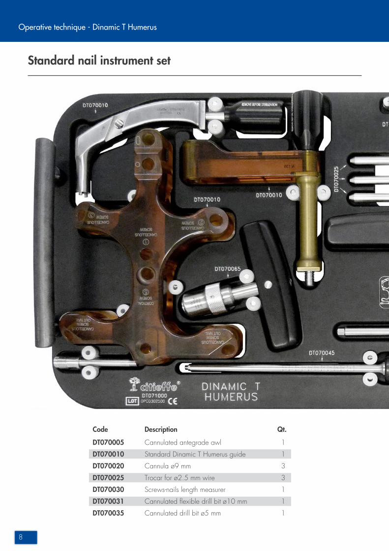
Standard nail instrument set
Operative technique - Dinamic T Humerus
DT070005 Cannulated antegrade awl 1
DT070010 Standard Dinamic T Humerus guide 1
DT070020 Cannula ø9 mm 3
DT070025 Trocar for ø2.5 mm wire 3
DT070030 Screws-nails length measurer 1
DT070031 Cannulated flexible drill bit ø10 mm 1
DT070035 Cannulated drill bit ø5 mm 1
Code Description Qt.

9
DT070045 Hexagonal screwdriver 1
DT070060 Tissue protection sleeve 1
DT070065 Quick-connect T handle 1
EBA-0030 Chuck for ø2,5-3 mm wires 1
SB-0260 5 mm hexagonal T screwdriver 1
DT071000 Dinamic T Humerus instrument tray, empty
NOTE Not included on the instrument trayDT070001 Graduated guide wire ø2,5 mm, L. 450 mmDT070300 Box for Dinamic T Humerus, emptyTK87170-2F-BL Sterilization box 580x270x110 mm, empty

10
11A 11B 11C
12A 12B 12C
Indications
Operative technique - Dinamic T Humerus
Standard nail
Proximal humerus fractures in all the sub-classifications:11A - 11B - 11C(AO classification)
Long nail
Diaphyseal humerus fractures in all sub-classifications:12A - 12B - 12Calso associated to proximal fractures(AO classification)
Figure 1
Figure 2

11
Patient positioning and access
Figure 3
Figure 4
Patient positioning
Position the patient in supine or half-sitting position (beach chair position).
Access
The skin incision should be parallel to the deltoid fibres at the level of the antero-lateral margin of the acromiun. Penetrate to the bone by blunt dissection through the muscle and supraspinatus tendon.Be careful to avoid damage to the axillary nerve and biceps tendon.
12
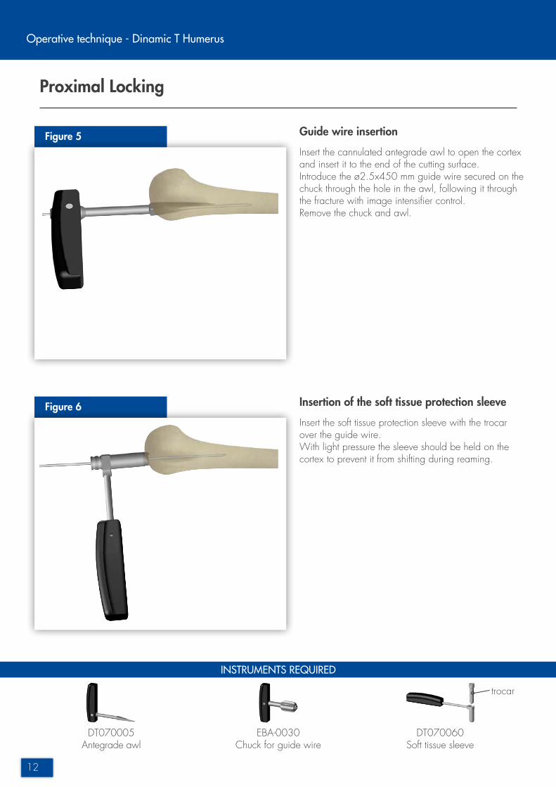
Proximal Locking
Figure 5
Figure 6
INSTRUMENTS REQUIRED
DT070005Antegrade awl
EBA-0030Chuck for guide wire
DT070060Soft tissue sleeve
Operative technique - Dinamic T Humerus
Guide wire insertion
Insert the cannulated antegrade awl to open the cortex and insert it to the end of the cutting surface.Introduce the ø2.5x450 mm guide wire secured on the chuck through the hole in the awl, following it through the fracture with image intensifier control.Remove the chuck and awl.
Insertion of the soft tissue protection sleeve
Insert the soft tissue protection sleeve with the trocar over the guide wire.With light pressure the sleeve should be held on the cortex to prevent it from shifting during reaming.
trocar
13
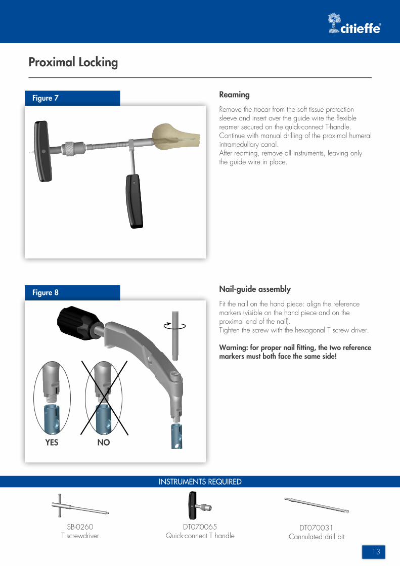
Proximal Locking
Figure 7
Figure 8
INSTRUMENTS REQUIRED
SB-0260T screwdriver
DT070065Quick-connect T handle
DT070031Cannulated drill bit
Reaming
Remove the trocar from the soft tissue protection sleeve and insert over the guide wire the flexible reamer secured on the quick-connect T-handle. Continue with manual drilling of the proximal humeral intramedullary canal.After reaming, remove all instruments, leaving only the guide wire in place.
Nail-guide assembly
Fit the nail on the hand piece: align the reference markers (visible on the hand piece and on the proximal end of the nail). Tighten the screw with the hexagonal T screw driver.
Warning: for proper nail fitting, the two reference markers must both face the same side!
YES NO

14
Proximal Locking
Figure 9
Figure 10
INSTRUMENTS REQUIRED
Operative technique - Dinamic T Humerus
Nail insertion
Introduce the nail over the guide wire into the canal and sink it until the reference notch on the hand piece is at the level of the cortex.Remove the guide wire.
Warning: for proper nail insertion, the reference notch must be at the level of the cortex!
First locking screw guide wire insertion
Unscrew the knob of the nail handpiece, insert the radiolucent proximal guide and lock it by retightening the knob.Insert the cannula and trocar in guide hole no. 1 . Ensure that the trocar is in contact with the cortex.Insert the guide wire (included in the nail packaging) through the trocar up to the second cortex. This is important to determine the correct length of the locking screw.
Note For skin incision use the single use surgical knife through the soft tissue protection guide
DT070020Cannula
DT070025Trocar
DT070010Standard guide
40470711Single use knife
Reference notch

15
Proximal Locking
Figure 11
Figure 12
INSTRUMENTS REQUIRED
Locking screw guide wire insertion
Repeat the above steps to insert the next two guide wires (included in the nail packaging) into guide holes no. 2 and no. 3 .Check proper insertion of the guide wires under image intensification in axillary projection.
Locking screw measurement
Fit the ruler on the first guide wire in contact with the trocar, which should remain in contact with the cortex. The end of the guide wire indicates, on the graduated scale, the locking screw length to be implanted.In case of an intermediate measurement it is advisable to use the smaller size locking screw.Be careful to insert the screw ruler correctly as indicated by the arrow marked on the instrument.
Warning: this measurement procedure is the same for all locking screws!
DT070020Cannula
DT070025Trocar
DT070030Length measurer

16
Proximal Locking
Figure 13
INSTRUMENTS REQUIRED
Figure 14
Operative technique - Dinamic T Humerus
Cephalic (cancellous) screws insertion
Remove the trocar from the cannula, leaving the wire in place. If the cortex texture so requires, it is possible to use the cannulated drill bit secured on a chuck or a hand drill (secured on the quick-connect T handle.Introduce the drill bit on the guide wire and advance until reaching the stop ring (always check that the cannula is in contact with the cortex). Remove both the drill bit and the guide wire, leaving the cannula inserted.
NOTE Always check that the guide wire is not being pushed deeper by the drilling action.
Screw insertion with the screwdriver
Position the screw previously measured screw on the screwdriver and lock it by turning the locking knob clockwise.The screwdriver has an hexagonal recess in the knob, to be used with a T screwdriver in case of excessive tightening.
DT070035Cannulated drill bit
DT070045Hexagonal screwdriver
SB-0260T screwdriver
DT070065Quick-connect T handle

17
Proximal Locking
Figure 15
Figure 16
INSTRUMENTS REQUIRED
Cephalic (cancellous) screw insertion
Insert the first screw in guide hole no. 1 :insertion can be measured on the scale, and is complete when reference “0” reaches the edge of the cannula.Complete the insertion of the cephalic screws according to the numerical sequence marked ont he guide.
Cortical screw insertion
If the fracture type so requires insert a cortical screw with the same technique through hole no. 5 using the screwdriver up to the “0” reference.The guide wire tip used for predrilling must go beyond the second cortex by 2 mm.
DT070045Hexagonal screwdriver

18
Standard nail. Distal Locking
INSTRUMENTS REQUIRED
Figure 17 Distal locking
3 different types of distal locking are available (static, dynamic, static-dynamic) as showed in the figure.
Distal screw insertion
In the distal part of the centering guide there are two markers that identify the hole and slot for distal locking.Using the cannulated drill bit (secured on a chuck) or a hand drill (secured on the quick-connect T handle), advance the cannulated drill bit over the guide wire up to the stop ring, always checking that the cannula is in contact with the cortex.After choosing the type of distal locking to be used, insert the screws following the same procedure.
STATICScrew position:proximal hole
DYNAMICScrew position:distal slot
STATIC-DYNAMICScrews position:proximal hole and distal slot
DT070020Cannula
DT070025Trocar
DT070030Length measurer
DT070035Cannulated drill bit
DT070045Hexagonal screwdriver
Figura 18
Operative technique - Dinamic T Humerus

19
Standard nail
Figure 19 Final assembly
INSTRUMENTS REQUIRED
DT070045Hexagonal screwdriver
Complete the implant by inserting the end cap, secured on the screwdriver, on the proximal part of the nail.it is available in 3 sizes: 1 standard (supplied with the nail) and 2 long (4 and 8 mm more than the standard), to be used in case of deep nail insertion.

20
Long nail. Fracture reduction and length measurement
Figure 20
Operative technique - Dinamic T Humerus
Nail length measurement
Insert the ruler on the wire guide and bring it in contact with the humeral head.Check under image intensification that the ruler does not penetrate the reamed bone canal.The end of the guide wire on the graduated scale indicates the length of the nail to be implanted. The size of the nail indicated is 20 mm shorter than the length of the guide wire inserted in the medullary canal.This is to allow for the conical shape of the proximal diaphyseal canal.
For proximal locking please follow the operative steps described from page 14 to page 17.
Fracture reduction
To facilitate fracture reduction, the fracture alignment and guide exchange tool can be used.Should this tool be used for fracture reduction see operative steps illustrated in figures 6 - 7 - 20.
INSTRUMENTS REQUIRED
DT070030Length measurer
DT070015Fracture alignment device
Extremity of the guide wire
Figure 21
21
INSTRUMENTS REQUIRED
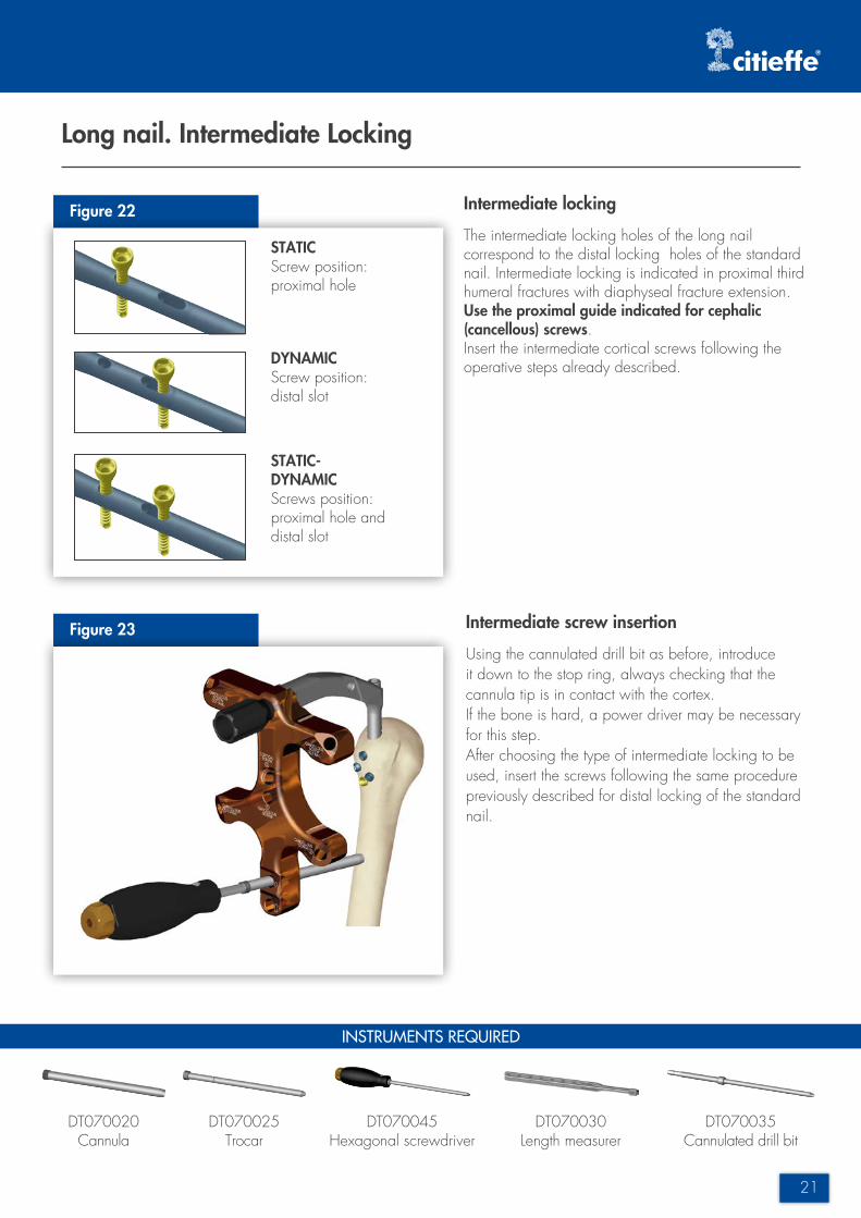
Long nail. Intermediate Locking
Figure 22
Figure 23
Intermediate locking
The intermediate locking holes of the long nail correspond to the distal locking holes of the standard nail. Intermediate locking is indicated in proximal third humeral fractures with diaphyseal fracture extension.Use the proximal guide indicated for cephalic (cancellous) screws.Insert the intermediate cortical screws following the operative steps already described.
STATICScrew position:proximal hole
DYNAMICScrew position:distal slot
STATIC-DYNAMICScrews position:proximal hole and distal slot
Intermediate screw insertion
Using the cannulated drill bit as before, introduce it down to the stop ring, always checking that the cannula tip is in contact with the cortex.If the bone is hard, a power driver may be necessary for this step.After choosing the type of intermediate locking to be used, insert the screws following the same procedure previously described for distal locking of the standard nail.
DT070020Cannula
DT070025Trocar
DT070030Length measurer
DT070035Cannulated drill bit
DT070045Hexagonal screwdriver

22
Long nail. Distal Locking
Operative technique - Dinamic T Humerus
Figure 24
Figure 25
INSTRUMENTS REQUIRED
DT070012Distal centering guide
Distal guide assembly
Remove the proximal centering guide and attach the proximal hand piece to the nail hand-piece, checking that the “HEAD” marking is facing proximally and the “FEET” marking distally.Fit the distal guide to the proximal hand piece according to the limb side being treated and the nail length inserted.
Note The only function of the guide is to facilitate centering of the distal holes. It is the operators’ responsibility to carry out the technique for isolating the soft tissues.
Distal centering guide components:Radiolucent distal block: for a clear radiographic view of the screw insertion areaCentering collimator: for alignment of the guide hole with the nail holeTranslator: for adjusting the position of the distal blockDistal guide: has a series of holes to fit all the available screw lengthsProximal hand piece: this is the connection element to the nail hand piece
proximal hand piecelocking knob
distal guidetranslator
radiolucentdistal block
collimate
locking knob
23
A B C
Long nail. Distal Locking
Figure 26
Figure 27
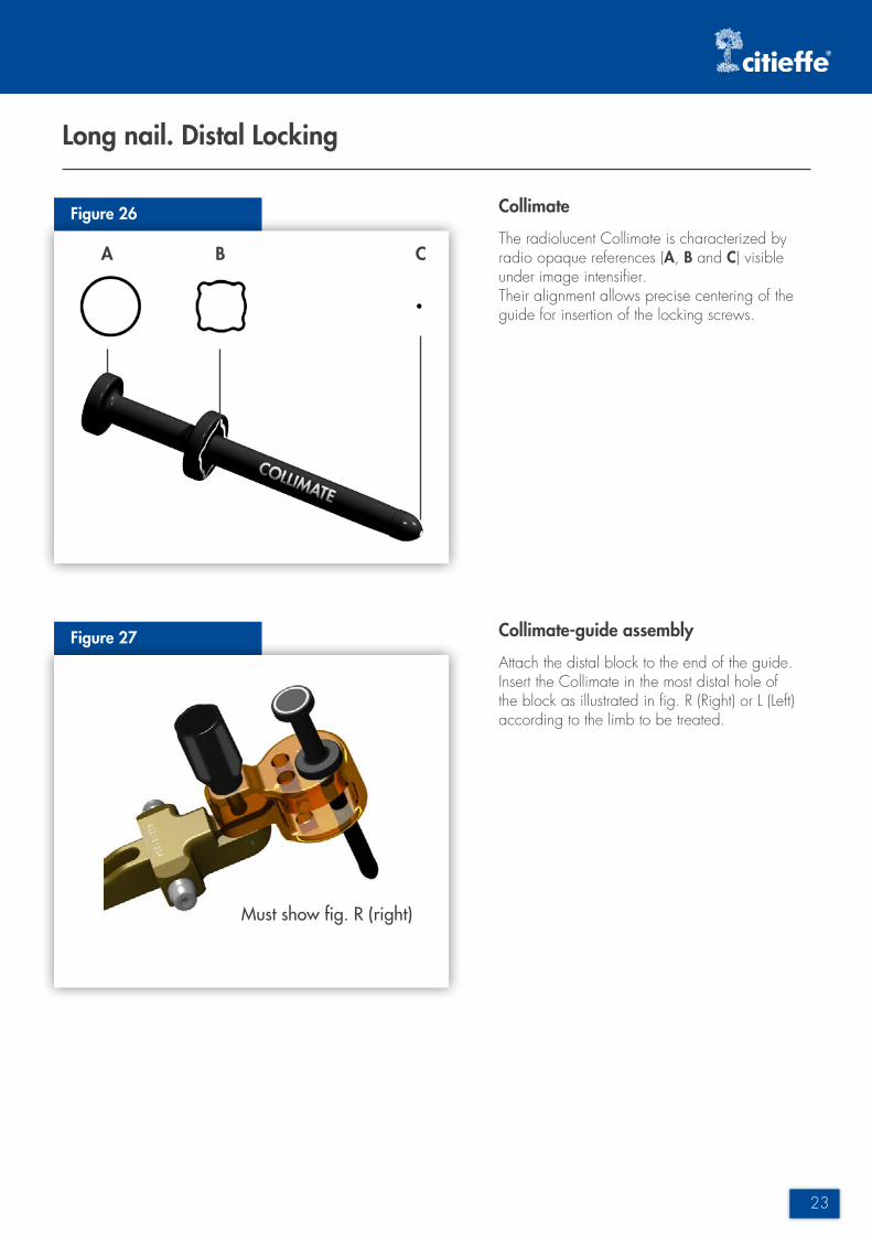
Collimate
The radiolucent Collimate is characterized by radio opaque references (A, B and C) visible under image intensifier.Their alignment allows precise centering of the guide for insertion of the locking screws.
Collimate-guide assembly
Attach the distal block to the end of the guide. Insert the Collimate in the most distal hole of the block as illustrated in fig. R (Right) or L (Left) according to the limb to be treated.
Must show fig. R (right)
24
Long nail. Distal Locking
Figure 28
Operative technique - Dinamic T Humerus
Figure 29
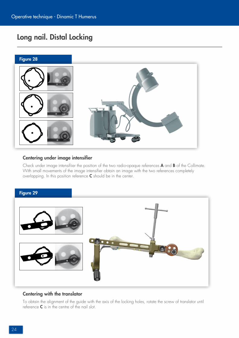
Centering under image intensifierCheck under image intensifiier the position of the two radio-opaque references A and B of the Collimate. With small movements of the image intensifier obtain an image with the two references completely overlapping. In this position reference C should be in the center.
Centering with the translatorTo obtain the alignment of the guide with the axis of the locking holes, rotate the screw of translator until reference C is in the centre of the nail slot.

25
Long nail. Distal Locking
Figure 30
Figure 31
INSTRUMENTS REQUIRED
Distal screws insertion
Introduce the cannula with the trocar through the static or dinamic hole of the distal block down to the skin. Make a longitudinal 25-30 mm incision in the skin level with the tip of the trocar.Penetrate to the bone by careful blunt dissection.With the trocar tip in contact with the bone surface, insert the guide wire so that the tip extends beyond the second cortex by about 2 mm.Check under image intensifier that the guide wire is in the nail locking hole by temporarily removing the cannula and the trocar. For the second locking screw, insert a second cannula with trocar and a second guide wire in the other hole before replacing the first guide wire with the screw. Insert the distal locking screws as already described.
DT070020Cannula
DT070025Trocar
DT070030Length measurer
DT070045Hexagonal screwdriver
Final assembly
Complete the implant by inserting the end cap, secured on the screwdriver, on the proximal part of the nail.it is available in 3 sizes: 1 standard (supplied with the nail) and 2 long (4 and 8 mm more than the standard), to be used in case of deep nail insertion.

26
CB
A
Optional screws
Figure 32
INSTRUMENTS REQUIRED
Operative technique - Dinamic T Humerus
Anterior screw
Assemble the anterior guide B on the metallic handle A by inserting the pin and by locking it with handle C.Insert the screw following the operative steps already described. Make sure not to damage thetendon of the long end of the brachial biceps muscle.
Out-nail screw
There are two holes for the out-nail screws on the proximal guide. These screws are indicated when it is necessary to better stabilize tuberosity detachments. It is suggested to use the Rondò cannulated screws ø5 mm. Position the soft tissue protection sleeve between the guide and the humerus and insert the cannula and trocar through the hole of the guide going through the soft tissue protection sleeve. Ensure that the trocar is in contact with the cortex. Introduce the wire into the trocar and drill the first cortex.
Note Only use the dedicated Rondò wires. Use of different wires can compromise measurement of screw length.
DT070020Cannula
DT070075Tissue protection sleeve
DT070050Trocar for ø2 mm wire
Figure 33
27
Optional screws
Figure 34
INSTRUMENTS REQUIRED
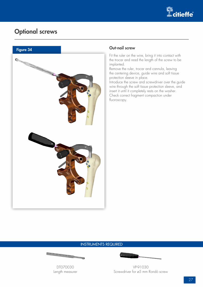
Out-nail screw
Fit the ruler on the wire, bring it into contact with the trocar and read the length of the screw to be implanted.Remove the ruler, trocar and cannula, leaving the centering device, guide wire and soft tissue protection sleeve in place.Introduce the screw and screwdriver over the guide wire through the soft tissue protection sleeve, and insert it until it completely rests on the washer.Check correct fragment compaction under fluoroscopy.
DT070030Length measurer
VP-91030Screwdriver for ø5 mm Rondò screw

28
Implant removal
Operative technique - Dinamic T Humerus
Skin incision
Expose the proximal end of the nail and identify the end cap.Unscrew the end cap by locking it on the hexagonal screw driver. Screw the proximal guide onto the end of the nail.Insert the cannula in the guide hole according to the screw to be removed.Make a skin incision and insert the trocar down to the screw.
INSTRUMENTS REQUIRED
Screw removal
Remove the trocar and, if necessary, release the head of each screw using a power driven screw removal drill bit, inserting it into the cannula and turning it anticlockwise.Anchor the hexagonal screwdriver with retention system to the screw head and remove the screw.Repeat the procedure for all the locking screws and then remove the nail.
DT070020Cannula
DT070070Drill bit screw removal
DT070045Hexagonal screwdriver
40470711Single use knife
DT070100Impactor extractor
Figure 35
Figure 36

29
Ordering information
Code Description
DT710150 ø7x150 mmproximal nail
ø7 mm diaphyseal nail
Code L. mm Bending
DT720200 200 RIGHT
DT720220 220 RIGHT
DT720240 240 RIGHT
DT720260 260 RIGHT
DT720280 280 RIGHT
DT720300 * 300 RIGHT
DT720320 * 320 RIGHT
Code L. mm Bending
DT725200 200 LEFT
DT725220 220 LEFT
DT725240 240 LEFT
DT725260 260 LEFT
DT725280 280 LEFT
DT725300 * 300 LEFT
DT725320 * 320 LEFT
* ON REQUEST
All nails are supplied in sterile package with:n° 1 standard end cap protectionn° 3 ø2.5x250 mm guide wires
DT731004 Protection end capstandard + 4 mm
DT731008 Protection end capstandard + 8 mm

30
ø5 mm cancellous screw
Code L. mm
DT750250 25
DT750275 27.5
DT750300 30
DT750325 32.5
DT750350 35
DT750375 37.5
DT750400 40
Code L. mm
DT750425 42.5
DT750450 45
DT750475 47.5
DT750500 50
DT750525 52.5
DT750550 55
ø5 mm cancellous screw - hydroxyapatite coated
Code L. mm
DT790350 35
DT790375 37.5
DT790400 40
DT790425 42.5
DT790450 45
Code L. mm
DT790475 47.5
DT790500 50
DT790525 52.5
DT790550 55
ø3.5 mm cortical screw
Code L. mm
DT735175 17.5
DT735200 20
DT735225 22.5
DT735250 25
DT735275 27.5
DT735300 30
Code L. mm
DT735325 32.5
DT735350 35
DT735375 37.5
DT735400 40
DT735425 42.5
DT735450 45
ø5 mm out-nail screw
Code L. mm
VP-15030 30
VP-15032 32
VP-15034 34
VP-15036 36
VP-15038 38
VP-15040 40
Code L. mm
VP-15042 42
VP-15044 44
VP-15046 46
VP-15048 48
VP-15050 50
VP-15055 55
Ordering information
Operative technique - Dinamic T Humerus

31
Ordering information NOT STERILE
DT070001 ø2.5 mm, L. 450 mm graduated guide wire
DT070005 Cannulated antegrade awl
DT070010 Dinamic T Humerus standard guide
DT070020 ø9 mm cannula (3 pcs.)
DT070025 Trocar for ø2.5 mm wire (3 pcs.)
DT070030 Screws nail length ruler
DT070031 ø10 mm cannulated flexible drill bit
DT070035 ø5 mm cannulated drill bit
DT070045 Hexagonal screwdriver
DT070060 Tissue protection sleeve
DT070065 Quick-connect T handle
EBA-0030 Chuck for ø2.5-3 mm guide wire
SB-0260 5 mm hexagonal T screwdriver
DT070300 Box for Dinamic T Humerus screws, empty
DT071000 Dinamic T Humerus instrument tray, empty
TK87170-2F-BL Sterilization box 580x270x110 mm, empty
40470711 ø7 mm single use knife, blade 11 mm
66042 ø2.5 mm, L. 250 mm guide wire trocar tip
66220 ø2 mm, L. 270 mm Kirschner wire
DT070050 Trocar for ø2 mm wire
DT070075 Tissue protection sleeve
VP-91030 Screwdriver for ø5 mm Rondò screw
DT071001 Out-nail screws instrument tray, empty
Out-nail screws instrument
DT070070 Drill bit for screw removal
DT070100 Dinamic T Humerus nail extractor
DT070002 ø2.5 mm, L. 450 mm graduated guide wire with olive
DT070012 Dinamic T Humerus long nail distal centering guide
DT070015 Fracture alignment and guide wire exchange tool
DT070080 Impactor extractor for long Dinamic T Humerus nail
Standard nail instrument
Long nail instrument
Optional instrument (STERILE)
Removal instrument

z
Essential moves in Trauma
TC-0
03A
.UK
- Rev
. 8 -
03/2
015
- citi
effe
® r
eser
ves
the
right
to m
ake
chan
ges
with
out n
otic
e
Commercial and Administration Management Via Armaroli, 21 - Research and Development Via Armaroli,14 40012 Calderara di Reno (Bologna - Italy) - Tel +39 051 721850 - Fax +39 051 721870
[email protected] - www.citieffe.com
Dinamic T Humerus
Intramedullary nail


![[Forensics] traumatology 1](https://img.dokumen.tips/doc/110x75/55c475bdbb61ebbc228b45ab/forensics-traumatology-1.jpg)
![[Forensics] traumatology 2.ppt](https://img.dokumen.tips/doc/110x75/55ce4f98bb61eb46528b47b2/forensics-traumatology-2ppt.jpg)