Embed Size (px)
Citation preview

Digital System
Microprocessor project
Fabrice Ben Hamouda, Yoann Bourse, Hang Zhou
2009-2010 : Semestre 1
Abstract
This paper describes our conception of a microprocessor, for the “Systeme Digital” course. Wewill emphasize on the three main parts of the project, that is to say the netlist simulator, the assemblytranslator, and finally the microprocessor itself. Our primary aim was to be able to simulate a simpledigital watch on this microprocessor. Furthermore, we chose to develop a microprocessor close tothe MIPS architecture so that we could use the compiler program we have done for another coursein order to compile Ocaml directly on our microprocessor.
1

Contents
I Netlist simulator 4
1 Simulator overview 41.1 Global description . . . . . . . . . . . . . . . . . . . . . . . . . . . . . . . . . . . . . . . . 41.2 Netlist language . . . . . . . . . . . . . . . . . . . . . . . . . . . . . . . . . . . . . . . . . 41.3 Files, classes and main functions . . . . . . . . . . . . . . . . . . . . . . . . . . . . . . . . 5
1.3.1 Input files . . . . . . . . . . . . . . . . . . . . . . . . . . . . . . . . . . . . . . . . . 51.3.2 Programming . . . . . . . . . . . . . . . . . . . . . . . . . . . . . . . . . . . . . . . 5
1.4 Executable file and flags . . . . . . . . . . . . . . . . . . . . . . . . . . . . . . . . . . . . . 71.5 Interpreting or compiling ? . . . . . . . . . . . . . . . . . . . . . . . . . . . . . . . . . . . 71.6 Functioning scheme . . . . . . . . . . . . . . . . . . . . . . . . . . . . . . . . . . . . . . . . 7
2 Makefile & Compilation 82.1 Getting started . . . . . . . . . . . . . . . . . . . . . . . . . . . . . . . . . . . . . . . . . . 82.2 Targets and options . . . . . . . . . . . . . . . . . . . . . . . . . . . . . . . . . . . . . . . 82.3 Requirements and troubleshooting . . . . . . . . . . . . . . . . . . . . . . . . . . . . . . . 82.4 Speed of simulator . . . . . . . . . . . . . . . . . . . . . . . . . . . . . . . . . . . . . . . . 9
3 Simulation results 103.1 Theoretical considerations about required set of tests . . . . . . . . . . . . . . . . . . . . . 103.2 Full Adder . . . . . . . . . . . . . . . . . . . . . . . . . . . . . . . . . . . . . . . . . . . . . 103.3 Minus . . . . . . . . . . . . . . . . . . . . . . . . . . . . . . . . . . . . . . . . . . . . . . . 103.4 Counter modulo 2 . . . . . . . . . . . . . . . . . . . . . . . . . . . . . . . . . . . . . . . . 113.5 Clock divider . . . . . . . . . . . . . . . . . . . . . . . . . . . . . . . . . . . . . . . . . . . 113.6 Counter modulo 24 . . . . . . . . . . . . . . . . . . . . . . . . . . . . . . . . . . . . . . . . 12
4 Further Improvements 144.1 Diagram display . . . . . . . . . . . . . . . . . . . . . . . . . . . . . . . . . . . . . . . . . 144.2 The time parameter . . . . . . . . . . . . . . . . . . . . . . . . . . . . . . . . . . . . . . . 144.3 Boolean constants . . . . . . . . . . . . . . . . . . . . . . . . . . . . . . . . . . . . . . . . 144.4 RAM/ROM primitives . . . . . . . . . . . . . . . . . . . . . . . . . . . . . . . . . . . . . . 144.5 Circuit-based digital watch . . . . . . . . . . . . . . . . . . . . . . . . . . . . . . . . . . . 15
5 Doxygen documentation 15
II Assembly language and microprocessor specification 16
6 Overview 166.1 Schema . . . . . . . . . . . . . . . . . . . . . . . . . . . . . . . . . . . . . . . . . . . . . . 176.2 Registers . . . . . . . . . . . . . . . . . . . . . . . . . . . . . . . . . . . . . . . . . . . . . . 176.3 Carry and zero registers . . . . . . . . . . . . . . . . . . . . . . . . . . . . . . . . . . . . . 18
6.3.1 Carry register . . . . . . . . . . . . . . . . . . . . . . . . . . . . . . . . . . . . . . . 186.3.2 Zero register . . . . . . . . . . . . . . . . . . . . . . . . . . . . . . . . . . . . . . . 18
6.4 External interfaces . . . . . . . . . . . . . . . . . . . . . . . . . . . . . . . . . . . . . . . . 186.5 Timer and sleep mode . . . . . . . . . . . . . . . . . . . . . . . . . . . . . . . . . . . . . . 18
7 Instructions set 197.1 Real instructions . . . . . . . . . . . . . . . . . . . . . . . . . . . . . . . . . . . . . . . . . 197.2 Pseudo-instructions . . . . . . . . . . . . . . . . . . . . . . . . . . . . . . . . . . . . . . . . 20
2

8 Assembly translation 218.1 Getting started . . . . . . . . . . . . . . . . . . . . . . . . . . . . . . . . . . . . . . . . . . 218.2 Quick tour of the program code . . . . . . . . . . . . . . . . . . . . . . . . . . . . . . . . . 21
8.2.1 Parsing . . . . . . . . . . . . . . . . . . . . . . . . . . . . . . . . . . . . . . . . . . 228.2.2 Handling of instructions . . . . . . . . . . . . . . . . . . . . . . . . . . . . . . . . . 228.2.3 Simulation . . . . . . . . . . . . . . . . . . . . . . . . . . . . . . . . . . . . . . . . 23
8.3 Syntax . . . . . . . . . . . . . . . . . . . . . . . . . . . . . . . . . . . . . . . . . . . . . . . 238.4 Watch example . . . . . . . . . . . . . . . . . . . . . . . . . . . . . . . . . . . . . . . . . . 23
III Microprocessor realisation 24
9 Realisation 249.1 PHP Netlist generation . . . . . . . . . . . . . . . . . . . . . . . . . . . . . . . . . . . . . 249.2 Presentation of involved circuits . . . . . . . . . . . . . . . . . . . . . . . . . . . . . . . . . 249.3 A new simulator flag . . . . . . . . . . . . . . . . . . . . . . . . . . . . . . . . . . . . . . . 25
10 Improvements 2510.1 Seven Segments and Graphical Output . . . . . . . . . . . . . . . . . . . . . . . . . . . . . 2510.2 Ocaml Compilation . . . . . . . . . . . . . . . . . . . . . . . . . . . . . . . . . . . . . . . . 26
11 How to use our Simulator 26
12 Results 2612.1 Digital watch . . . . . . . . . . . . . . . . . . . . . . . . . . . . . . . . . . . . . . . . . . . 2612.2 Result Comparison . . . . . . . . . . . . . . . . . . . . . . . . . . . . . . . . . . . . . . . . 27
References 27
3
Part I
Netlist simulatorThis section describes the first step toward the simulation of a digital watch. The final result will bebased on a microprocessor that we will have created, and which will require a netlist simulator, that isto say a program able to interpret and simulate logical circuits.
1 Simulator overview
1.1 Global description
This simulator was built in C++, mainly because this project immediately appeared to us under theform of classes and pointers. Since the beginning, for purposes of performance, we wanted our simulatorto have two main modes : interpreting the data or compiling it. In the following subsections, you will seehow we translated circuits into text, how we treated this text by C++ programs and how we configuredthe two modes of output.
1.2 Netlist language
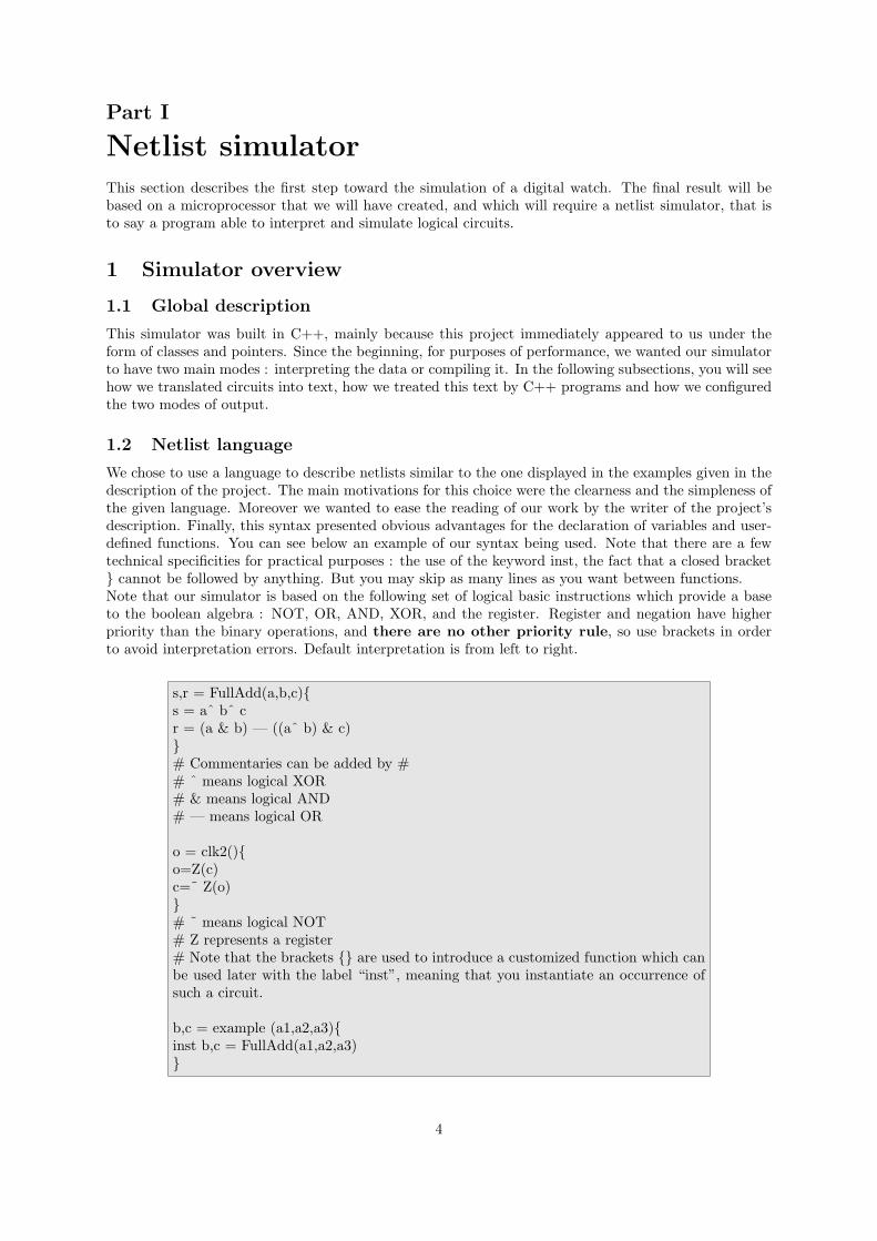
We chose to use a language to describe netlists similar to the one displayed in the examples given in thedescription of the project. The main motivations for this choice were the clearness and the simpleness ofthe given language. Moreover we wanted to ease the reading of our work by the writer of the project’sdescription. Finally, this syntax presented obvious advantages for the declaration of variables and user-defined functions. You can see below an example of our syntax being used. Note that there are a fewtechnical specificities for practical purposes : the use of the keyword inst, the fact that a closed bracket} cannot be followed by anything. But you may skip as many lines as you want between functions.Note that our simulator is based on the following set of logical basic instructions which provide a baseto the boolean algebra : NOT, OR, AND, XOR, and the register. Register and negation have higherpriority than the binary operations, and there are no other priority rule, so use brackets in orderto avoid interpretation errors. Default interpretation is from left to right.
s,r = FullAdd(a,b,c){s = aˆ bˆ cr = (a & b) — ((aˆ b) & c)}# Commentaries can be added by ## ˆ means logical XOR# & means logical AND# — means logical OR
o = clk2(){o=Z(c)c=˜ Z(o)}# ˜ means logical NOT# Z represents a register# Note that the brackets {} are used to introduce a customized function which canbe used later with the label “inst”, meaning that you instantiate an occurrence ofsuch a circuit.
b,c = example (a1,a2,a3){inst b,c = FullAdd(a1,a2,a3)}
4

We will also have to specify the value of several input variables. The syntax we chose is similar to anarray whose columns are separated by a tabulation. It is possible to reproduce a line a certain amountof times using the symbol *, or skip a cycle by an empty line (therefore every empty line creates a newcycle with no forced modification). You may also try to force the value of a variable that is not an input.It will take this value of the beginning of the cycle but may be overwritten by some other functions.Below stands an example :
a1 a2 a30 0 10 1 0∗51 1 0
1.3 Files, classes and main functions
1.3.1 Input files
• input.netThis files contains the netlist description of the used circuits. You must define custom circuitsbefore instantiating them.
• input.setThis files contains the default number of clock cycles, and the values of customized variables foreach cycle.
1.3.2 Programming
• mainThis file is the core of the simulator, as in any C++ project. It loads the various modules (describedbelow) whenever needed. It defines the two possible ways to use the simulator : the compilationor the interpretation. It is also in this file that while loops represent clock cycles.
• toolsHere are defined several tools, especially to manipulate vectors more easily.
• parserVarThis module creates an item of the settingfile class which can be seen as a flow to read the file“settings.net”.
settingfileThe variable s contains the source file under the form of a stream.Variable repeat record the number of line repetitions yet to come.init settings initializes the global settings at the beginning of the program.forced var is a function called every cycle in order to define the value of givenvariables.
• parserNetlistThis file analyses input.net. The parser uses step variables to memorize its position in the syntaxanalysis : (see the doxygen documentation for more informations)
5

Creating a function :0 -outputs- = 1 -function’s name- (2 -inputs-) 3 -waiting for the bracket- {4 -function core-}
Instantiating a function :-1 : no instantiating function-2 : receive output of non instantiating function
The function ReadFunction analyses the text of a function : il calls the functions Process-Expression which analyses a logical expression, and the functions ProcessName which are thecore of the creation of the various functions. They are all subfunctions of ParserNetList, whichhandles as well the topological sort of the functions thanks to the subfunction SortlistOps.
• graphThe name of this file is due to the graph structure induced during the parsing, whose consequencesare present all over the program.
variableThis class represents a variable, identified by a name and a value. We register thelist of operations of which the variable is an input and we define several functionsto read or modify the variable’s parameters.
registerVThis class is our mean to deal with the problem of registers : every registerV containstwo pointers towards “input” variable and “output” variable : the functionSaveRegister() loads the value of the input and the function NextClockEdge()copies it into the output. The internal value of the register allows an easyinstantiation of functions : only registers are copied, not the combinatorial graph.
operationAn operation is the heart of a function. Every object of this class contains twovariable* arrays pointing to the inputs and outputs of the operation, and afunctionInst pointer heading towards the function the operation is used in.
• functionUser
functionUserThis class is the global one, defining every user-customized function of which thevarious circuits will be an instance. It contains global parameters shared by allinstances of a function such as input, outputs, registers and the list of oper-ations sorted topologically.
• functionInst This is a leftover of a previous version of our project, still accessible through theflag --nogc (no graph copy). Previously, functionUser was nothing but a generic pattern, andreal circuits were instances of functionInst, which used the pattern in order to compute. Yet,this system had a major problem with combinatorial loops when the output of a function wasconnected to one of its inputs, even through a register. In order to correct that shortcoming, wedecided that a circuit would not be an instance of functionInst, but a copy of functionUser to thegeneral functionUser which represent the whole circuit.
6
1.4 Executable file and flags
We allowed the use of flags in order for the user to set various option or parameters when calling theexecutable file resulting from the compilation of our simulator. Following syntaxes are accepted :
simulateur [options] netlistsimulateur -h (for help and a total list of possible flags)
where main options are :-v : displays comments about what the program is doing (verbose)-q : hides the simulation results-p period : length of a clock cycle (in seconds)-c : compiling mode instead of interpreting--cc bin : use “bin” compiler instead of gcc -s settings : path to the setting file-n n : number of cycles--column s : size of a columnnetlist : path to the netlist file--noits : no intermediate toposort (only final)
1.5 Interpreting or compiling ?
The compiling mode transforms the given circuit in a C program : sim.C and then compiles it. Thisway, the circuit is an independent program and therefore a lot faster. On the other hand, it is impossi-ble to specify or to force the value of variables with a setting file. Here is an overview of the two processes :
Compiling :- Variables declaration (CPutDeclarations)- Combinatorial computing (CPutCommands) whole users functions are copied, not only registers.- Save of registers (CPutRegistersSave)- Next clock, restoring registers (CPutRegistersNext)
Interpreting :Every time an operation invoilving a user-created function is called :- Next clock, restoring registers (NextClockEdge)- Combinatorial computing (Eval)- Save registers (SaveRegisters)
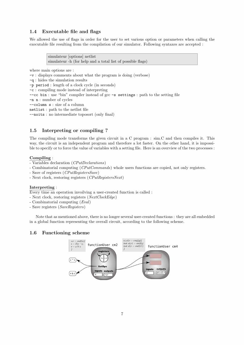
Note that as mentioned above, there is no longer several user-created functions : they are all embeddedin a global function representing the overall circuit, according to the following scheme.
1.6 Functioning scheme
7

2 Makefile & Compilation
2.1 Getting started
On Linux, open a command line console (in “simulateur” folder) and type :
• make 12345
• make watch : you will see a watch without microprocessor
To use compiling mode, you need GNU gcc compiler.On Linux, just add option SIM NS FLAGS=-c.Note that with --cc option you can specify options to gcc, for example optimization option like -O3 or-O2.
If you want, you can use CodeBlocks : http://www.codeblocks.org. There is a CodeBlocks project.Just open it.
2.2 Targets and options
We have created a Makefile to automatically compile the project and transform all *.php files (automaticgeneration of complex netlists, see 4.5 ) into netlist *.net files and to simulate them using if possible*.mem and *.set files. Important targets are :
• all : compile the project
• doc : compile this documentation
• doxygen : compile the doxygen documentation
• demo : execute all netlist
• 12345 : execute required for project (Full Adder, Minus, ...) netlist
• watch : print the watch (add some options to simulator to select the good period and the watchoutput format)
• netlists/%.run : execute the netlists/%.net or netlists/%.php netlist
• democlean : delete all generated netlists
• clean : delete all generated files except documentation and “simulateur” executable
• mrproper : delete all generated files without any exception
There are a lot of options, you can see the Makefile to have more informations :
• TEST=yes : compare results of simulation with saved results (in *.res files)
• TEST=res : automatically generate *.res files (you have to verify that the content is correct)
• SIM FLAGS : flags for simulator
• SIM NS FLAGS : flags for simulator for target that do not use a setting file (we use it for testing thecompilation mode : SIM NS FLAGS=-c)
2.3 Requirements and troubleshooting
In order for the makefile to work correctly, you will need to have installed support of PHP.
8

2.4 Speed of simulator
To have an approximative idea of the speed of our simulator, you can execute the watch without forcingthe period :
• time make netlists/watch.run SIM FLAGS=‘‘-n 1000000 --watch’’
• time make netlists/watch.run SIM FLAGS=‘‘-n 1000000 --watch -c’’
The time command print the time needed to execute the simulation. You can see that compiling modeis faster than interpreting mode. There is an overhead at the beginning because of time of compilationbut after that it is very fast. In addition, for real tests, it’s recommended to print nothing to stdout(because it takes a lot of time) with flag -q for simulator and to use clock cycles.
9

3 Simulation results
3.1 Theoretical considerations about required set of tests
For the following circuits, at each cycle t ∈ N, we call state the list (z1(t), ...zm(t)) of values of output ofregisters (zk) at the beginning of the cycle. At each cycle, inputs (i1(t), ..., in(t)) and state completelydefine the value of others variables since others variables only depend on value of inputs and of output ofregisters. In particular, state and inputs define outputs (let’s set (o1(t), ..., or(t)) be the vector of outputvalue at cycle t) and next output of registers (z1(t+1), ..., zm(t+1)) because the next output of a registeris exactly current value of input of this register. More precisely, there is one function f :
f : {0, 1}n+m → {0, 1}r+m
so that the following condition is true :
(o1(t), ..., or(t), z1(t + 1), ..., zm(t + 1)) = f(i1(t), ..., in(t), z1(t), ..., zm(t))
States are initialized that way :(z1(0), ..., zm(0)) = (0, ..., 0)
We notice that if inputs are constants (or if there is no input), ~z(t + 1) = (z1(t + 1), ..., zm(t + 1)) onlydepends on ~z(t) = (z1(t), ..., zm(t)) and on the constant inputs. Since there are only 2m possibilities forthe values of a vector in {0, 1}m, the sequence (~z(t))t∈N is periodic with a period less or equal than 2m.In addition, if at cycle t and cycle t′ (t′ 6= t), states are identical, the period is less than t′ − t.
In particular, you can notice that if ~z(t) = ~z(t + 1) for an cycle t, the state is never modified whenthe circuit is in the state ~z(t) and when input is i(t).
3.2 Full Adder
s,r = FullAdd(a,b,c){s = aˆ bˆ cr = (a & b) — ((aˆ b) & c)}
a b c0 0 00 0 10 1 00 1 11 0 01 0 11 1 01 1 1∗9
Simulation results :s r
0 0 01 1 02 1 03 0 14 1 05 0 16 0 17 1 1· · ·
This circuit doesn’t involve any register : any output will require no more than one clock cycle in orderto be computed. Therefore, we only need to try all the possible combinations for a, b and c (providedby magic masks).
3.3 Minus
The minus function is equivalent to negate the input and then add one to it. This means that the first1 (the least important one) will keep the value 1. All the 0 before will not change, and after it, 0 will beturned into 1 and 1 into 0. That’s the property we will have to check on our circuit....100100→ negation : ...011011→ incrementing : ...011100In order to prove this function, we modified the netlist so as to print the output of the register (the
10

only state of the circuit). As long as input is x = 0, the state c is 0 (constant input). An input x = 1changes the state c to 1 and output y = 1. After that, all bit are changed to their opposite and thatnever changes the state c (because c(2) = c(3) = 1 for input x = 0 and c(3) = c(4) = 1 for input x = 1).We have therefore proved correctness of the circuit with the 5 first lines of simulation results.
y,c = minus b(x){y = x ˆ cc = Z(x—y)}
x01101∗12
Simulation results :y c
0 0 01 1 02 0 13 1 14 0 1· · ·
3.4 Counter modulo 2
We need to check that the counter only counts clock cycles when x=1, and that s + 2r corresponds tothe number of such cycles, modulo 2. With complete simulation, you can see that when the input isx = 0, this do not change the state (because s(0) = s(1) = 0 and s(2) = s(3) = 0). Hence the numberof cycle with input 0 between two cycles with input 1 has no importance. There is only left to verifythat, in all states (s = 0 or s = 1), when input is 1, counter increments itself (s being the main digitand r the overflow carry) and it is the case. The 5 first lines of simulation results are sufficient to provecorrectness of the circuit.
s,r = cm2(x){s = Z(x ˆ s)r = x & s}
x100101∗11
Simulation results :r s
0 0 01 1 02 1 03 1 14 0 05 1 16 0 07 1 1· · ·· · ·
3.5 Clock divider
This circuit doesn’t need any input (only the specification of the number of clock cycles to execute). weneed to verify that it produces a periodic output. Hence, we just need to check 22 = 4 values to be surethat it is a clock divider : first 4 lines are enough.
11

o = clk2(){o=Z(c)c=˜ Z(o)}
∗16
Simulation results :o
0 01 12 13 04 05 16 17 08 0· · ·
3.6 Counter modulo 24
This counter is based on a counter modulo 32 = 25 that is to say 5 CM2 in a row. We used the factthat the CM2 contain actually two different numbers : the current number in outputs si and the nextnumber to come, in zi, just before the register. The difficulty to this counter is to reset the outputs whenthe counter reaches 24. We decided to use an additionnal feedback condition able to reset all si, thatis to say that we intercept the future number to come when it is . . . 0011000 = 24 and replace it with. . . 00000 = 0[24].
For purposes of legibility, we detailed the first part of the input (that is to say 1 / *23 / 0 / *5 ).
12

s,r,z = cm2m(x,v){z = x ˆ ss = Z(z) & vr = x & s}
s5,s4,s3,s2,s1 = cm24(y){tt = ˜ (z4 & z5)inst s1,r1,z1 = cm2m(y,tt)inst s2,r2,z2 = cm2m(r1,tt)inst s3,r3,z3 = cm2m(r2,tt)inst s4,r4,z4 = cm2m(r3,tt)inst s5,r5,z5 = cm2m(r4,tt)}
x11111111111111111111111000001∗27
Simulation results :s5 s4 s3 s2 s1
0 0 0 0 0 01 0 0 0 0 12 0 0 0 1 03 0 0 0 1 14 0 0 1 0 05 0 0 1 0 16 0 0 1 1 07 0 0 1 1 18 0 1 0 0 09 0 1 0 0 110 0 1 0 1 011 0 1 0 1 112 0 1 1 0 013 0 1 1 0 114 0 1 1 1 015 0 1 1 1 116 1 0 0 0 017 1 0 0 0 118 1 0 0 1 019 1 0 0 1 120 1 0 1 0 021 1 0 1 0 122 1 0 1 1 023 1 0 1 1 124 1 0 1 1 125 1 0 1 1 126 1 0 1 1 127 1 0 1 1 128 1 0 1 1 129 0 0 0 0 030 0 0 0 0 131 0 0 0 1 0· · ·52 1 0 1 1 153 0 0 0 0 0· · ·
13

4 Further Improvements
4.1 Diagram display
To improve the legibility of the outputs, we have imagined another display of the output : instead of 0and 1, the --diag flag causes the output to be a frieze where 0 is bottom and 1 is top, as displayed onthe example.
4.2 The time parameter
In order to simulate the quartz periodic signal for the microprocessor, we have decided to allow the userto set the duration they want for a clock cycle. This is done thanks to an additional loop and the use ofthe function gettime of day.
4.3 Boolean constants
We added the possibility to use boolean constants 0 and 1 directly in the netlist, therefore avoiding theneed to declare an alimentation like VDD.
4.4 RAM/ROM primitives
As a transition toward the work that is simulating a whole microprocessor, we have added to our projectROM/RAM primitives. You can instantiate ROM or RAM with the following code :
ram do1, do2 = name(ao2, ao1, ao0, w, ai2, ai1, ai0, di1, di0)rom do1, do0 = name(ao2, ao1, ao0)
First character : Data or AddressSecond character : In or Out, that means for writing (in) or for reading (out)Third character : level of bit (2 being the most significant bit)w : write input data into input address if equal to 1
Size of address bus and data bus are determined by the number of arguments and returned values. Moreprecisely, if there are n returned values and m arguments, data bus is n bits length and address bus ism−n bits length for ROM and m−n−1
2 bits length. The order of argument is this mentioned above. Sizeof memory is 2a if address bus has a bits. Names of variables have no importance.
Reading is executed before writing. You can also define RAM and ROM through a *.mem file usingthe flag : -m file. The content of the file should follow that pattern, with the keyword mem :
mem:Name3212mem:Name2...
This uses a special functionInst called functionMem, which stores the data in a data vector.
14

4.5 Circuit-based digital watch
The conclusion of this simulation work was the simulation of a digital watch based on complex circuitsas describes in the courses provided by Mr Vuillemin. The netlists (”simulateur/netlists/watch.php“) ofthose gigantic circuits were created thanks to PHP scripts which offered a very clear way to display textin loops or recursive calls. It offered a nice transition towards the microprocessor-based digital watch,with for instance the creation of a graphic interface based on 7-segments display, activated by the flag--watch. This subject will be later discussed in our next report.
5 Doxygen documentation
A detailed documentation is available in the folder “simulateur/doc”, describing more precisely everyfile, class and function. Just type make doxygen to compile it.
15
Part II
Assembly language and microprocessorspecificationWe will now describe the specifications and features of the microprocessor we will be using to simulate adigital watch, thanks to the netlist simulator previously conceived. Assembly programs will be translatedinto digital instructions that the microprocessor will interpret in order to use correctly logical circuitsfor computation. The translation from assembly to machine language is performed by a program whichis also able to simulate the expected results of the assembly code.
6 Overview
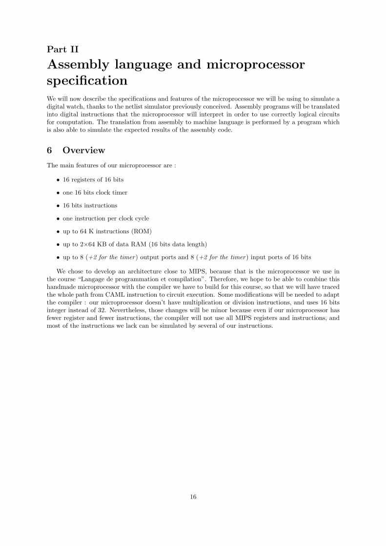
The main features of our microprocessor are :
• 16 registers of 16 bits
• one 16 bits clock timer
• 16 bits instructions
• one instruction per clock cycle
• up to 64 K instructions (ROM)
• up to 2×64 KB of data RAM (16 bits data length)
• up to 8 (+2 for the timer) output ports and 8 (+2 for the timer) input ports of 16 bits
We chose to develop an architecture close to MIPS, because that is the microprocessor we use inthe course “Langage de programmation et compilation”. Therefore, we hope to be able to combine thishandmade microprocessor with the compiler we have to build for this course, so that we will have tracedthe whole path from CAML instruction to circuit execution. Some modifications will be needed to adaptthe compiler : our microprocessor doesn’t have multiplication or division instructions, and uses 16 bitsinteger instead of 32. Nevertheless, those changes will be minor because even if our microprocessor hasfewer register and fewer instructions, the compiler will not use all MIPS registers and instructions, andmost of the instructions we lack can be simulated by several of our instructions.
16
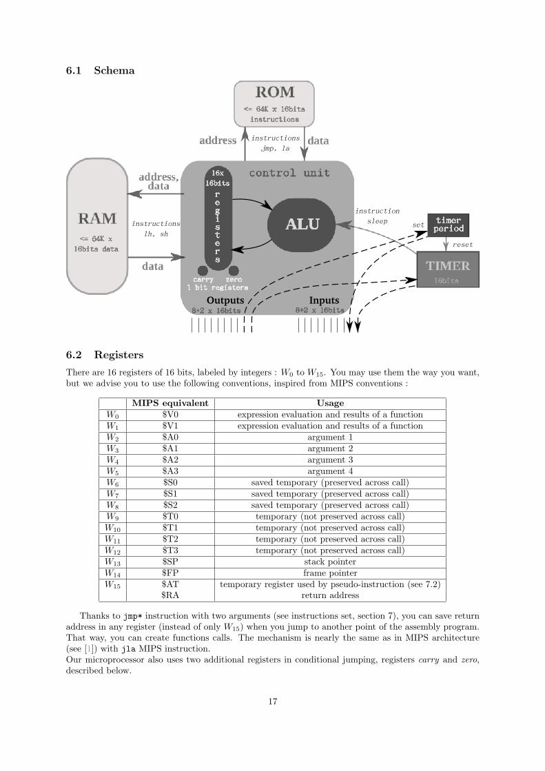
6.1 Schema
6.2 Registers
There are 16 registers of 16 bits, labeled by integers : W0 to W15. You may use them the way you want,but we advise you to use the following conventions, inspired from MIPS conventions :
MIPS equivalent UsageW0 $V0 expression evaluation and results of a functionW1 $V1 expression evaluation and results of a functionW2 $A0 argument 1W3 $A1 argument 2W4 $A2 argument 3W5 $A3 argument 4W6 $S0 saved temporary (preserved across call)W7 $S1 saved temporary (preserved across call)W8 $S2 saved temporary (preserved across call)W9 $T0 temporary (not preserved across call)W10 $T1 temporary (not preserved across call)W11 $T2 temporary (not preserved across call)W12 $T3 temporary (not preserved across call)W13 $SP stack pointerW14 $FP frame pointerW15 $AT temporary register used by pseudo-instruction (see 7.2)
$RA return address
Thanks to jmp* instruction with two arguments (see instructions set, section 7), you can save returnaddress in any register (instead of only W15) when you jump to another point of the assembly program.That way, you can create functions calls. The mechanism is nearly the same as in MIPS architecture(see [1]) with jla MIPS instruction.Our microprocessor also uses two additional registers in conditional jumping, registers carry and zero,described below.
17

6.3 Carry and zero registers
One of the most important difference with MIPS architecture is the lack of conditional instructionslike MIPS beq (see [1]). This lack is compensated by two 1 bit pseudo-registers carry and zero. Theyare unaccessible to the user. They are automatically updated by most instructions. We have someinstructions providing jump conditioned on the value of those two registers.
6.3.1 Carry register
Carry register is only updated by arithmetic operations (addu, subu, sub, sra, srl instructions, andpseudo-instructions which use these real instructions - see instructions set, section 7).
• addu Wdst Wsrc1 Wsrc2 : carry will be set if Wsrc1 + Wsrc2 ≥ 216 (values considered as unsigned)
• subu Wdst Wsrc1 Wsrc2 : carry will be set if Wsrc1 −Wsrc2 ≥ 0 (values considered as unsigned)
• sub Wdst Wsrc1 Wsrc2 : carry will be set if Wsrc1 −Wsrc2 ≥ 0 (values considered as signed)
• sra Wdst Wsrc : carry is the less significant bit of Wsrc
• sla Wdst Wsrc : carry is the less significant bit of Wsrc
For example, suppose that W0 = 10 and W1 = −4 = 216 − 4 :- addu W2 W0 W1 will set carry- subu W2 W0 W1 will clear carry because 10 < 216 − 4- sub W2 W0 W1 will set carry because 10 ≥ −4
6.3.2 Zero register
Zero is updated after each instruction using a destination register (Wdst in 7.instruction set). If the newvalue of Wdst is 0, zero will be set, otherwise it will be cleared.That way, you can easily jump if two registers are equal by jumping if the result of a xor on those tworegister is 0.
6.4 External interfaces
Programs can communicate with other module of the CPU through input and output instructions. Hereare the current mapping of address :
Input Output0-7 real 16 bits input port 0-7 real 16 bits output port 0-78 16 bits timer period9 16 bits timer
Default values are 0.
6.5 Timer and sleep mode
Our microprocessor has a 16 bits timer, that is to say a counter modulo period incremented at each clockcycle. A 0 period corresponds to a counter modulo 216 (default). You can set its period and its valuewith input and output instructions (see above).
Warning : If you change the period to a value less than or equal to current timer value, thecounter will not be reset. Hence it is recommended to manually reset counter (by setting it to 0) afterchanging its period.
You can put microprocessor into sleep mode with sleep instruction. Nothing is done until the timerreaches its period. This feature is important for the digital watch, because we need to increment secondswith the good period.
18

7 Instructions set
You will find below the set of instructions used by our microprocessor. Assembly programs used withour translator can use real microprocessor instructions or pseudo-instructions that will be converted intoseveral real instructions by the translator.
We will use the following notations :
Wx register Wx
K (n) constant of n bits 4, 8 or 16 bitslo(*) low bits (half) of * 4 or 8 bitshi(*) high bits (half) of * 4 or 8 bitsaddr(label) address of the label 16 bits
7.1 Real instructions
Here are real instructions, the four last columns displaying the instruction code saved in a ROM program.
19

ALU instructions4×4 bits
addu Wdst Wsrc1 Wsrc2 Wdst ←Wsrc1 + Wsrc2 0 dst src1 src2adduc Wdst Wsrc1 Wsrc2 Wdst ←Wsrc1 + Wsrc2 + carry 1 dst src1 src2subu1 Wdst Wsrc1 Wsrc2 Wdst ←Wsrc1 −Wsrc2 2 dst src1 src2sub1 Wdst Wsrc1 Wsrc2 Wdst ←Wsrc1 −Wsrc2 3 dst src1 src2xor Wdst Wsrc1 Wsrc2 Wdst ←Wsrc1 xor Wsrc2 4 dst src1 src2or Wdst Wsrc1 Wsrc2 Wdst ←Wsrc1 or Wsrc2 5 dst src1 src2and Wdst Wsrc1 Wsrc2 Wdst ←Wsrc1 and Wsrc2 6 dst src1 src2
move Wdst Wsrc Wdst ←Wsrc 8 dst src 0not Wdst Wsrc Wdst ← not Wsrc 8 dst src 1sra Wdst Wsrc Wdst ← shift2 right arithmetic3 of Wsrc 8 dst src 2srl Wdst Wsrc Wdst ← shift2 right logical of Wsrc 8 dst src 3
Jump instructionsjmp Wsrc Jump to Wsrc 9 0 src 0jmpz Wsrc Jump to Wsrc if zero 9 0 src 2jmpc Wsrc Jump to Wsrc if carry 9 0 src 4jmpnz Wsrc Jump to Wsrc if non zero 9 0 src 3jmpnc Wsrc Jump to Wsrc if non carry 9 0 src 5
jmp Wsrc Wret Jump to Wsrc 9 ret src 8save next address to Wret
jmpz Wsrc Wret Jump to Wsrc if zero 9 ret src 10save next address to Wret
jmpc Wsrc Wret Jump to Wsrc if carry 9 ret src 12save next address to Wret
jmpnz Wsrc Wret Jump to Wsrc if non zero 9 ret src 11save next address to Wret
jmpnc Wsrc Wret Jump to Wsrc if non carry 9 ret src 13save next address to Wret
Load/Store instructionslhi4 Wdst K (8) hi(Wdst)← K 10 dst hi(K) lo(K)lli3 Wdst K (8) lo(Wdst)← K 11 dst hi(K) lo(K)lh Wdst Wsrc Wdst ← RAM(Wsrc) 8 dst src 4sh Wsrc1 Wsrc2 RAM(Wsrc2) ←Wsrc1 12 0 src1 src2
Input/Output - other instructionsoutput K (4) Wsrc output(K) ←Wsrc 13 0 K srcinput Wdst K (4) Wdst ← input(K) 8 dst K 5
sleep Sleep (see 6.5) 8 0 0 8
7.2 Pseudo-instructions
Since real instructions lack some important practical functions, we have created pseudo-instructions.Every time the assembly translator sees such an instruction, this is immediately translated into realinstructions.
1The only difference between sub and subu is the carry modification (see 6.3.1).2One bit shift. Notice that left shift can be done with addu instruction.3Arithmetic means that sign bit is copied.4Instructions lli and lhi do not modify or erase the unused part of the register, respectively hi(Wsrc) and lo(Wsrc).
20

Warning : Some pseudo-instructions use W15 registers without saving it.
Load/Store pseudo-instructionsli Wdst 0 xor Wdst Wsrc Wsrc
li Wdst K (16) lhi Wdst hi(K)lli Wdst lo(K)
la Wdst label li Wdst addr(label)
Arithmetic pseudo-instructionsaddui Wdst K (16) Wsrc li W15 K
addu Wdst W15 Wsrc
adduci Wdst K (16) Wsrc li W15 Kadduc Wdst W15 Wsrc
subui Wdst K (16) Wsrc li W15 Ksubu Wdst W15 Wsrc
subi Wdst K (16) Wsrc li W15 Ksub Wdst W15 Wsrc
8 Assembly translation
The second step of our project was to create a program able to translate assembly language into mi-croprocessor instructions (16 bits integers). The program has also a simulation mode, which enable theuser to overview the content of the register through the time, so that they can fix their programs.
8.1 Getting started
Like for the simulator, you may compile the assembly translator by Code Blocks or our own makefile(just type make in “asm” folder). You will then be able to use the program “asm” with the followingsyntax :
asm [options] sourcesasm -h for help
Where option are :-v for verbose mode--sim to launch the simulation after asembly translation--rc to display the content of the registers during simulation-p 0 period of one cycle-n 0 maximum number of cycles--watch display a watch instead of just printing the contents of outputs (see bellow)
In the watch mode, output ports 0 to 5 corresponds to a 7-segment digits (each bit is a segment - theorder is the traditional order : less significant bit is the upper segment). The simulator display the watcheach time you wrote something in output port 0. That’s why you have to update this port at the end,when you want to update the watch. Please see example “asm/tests/watch.asm” for more informations.
Notice that targets Makefile are nearly the same as simulator ones. You can so automatically runtests by typing : make demo TEST=yes. This will run simulator one each *.asm file of folder “asm/tests”for 1000000 cycles and compare the results with *.res file.
8.2 Quick tour of the program code
Here is a brief description of the way the assembly translator works. We hope it will be helpful if youever have to look up the source code.
21

8.2.1 Parsing
The file is first parsed in the parser module. A simple handmade loop gets the arguments and thename of the instructions. A counter stores the number of instructions already studied so that the parserstores with every label name the number of the instruction it corresponds to. Pseudo-instructions mayincrement the counter more than once because they may introduce a lot of new real instructions. Allthose instructions are stored in a vector.
8.2.2 Handling of instructions
A map module stores the main informations about instructions and pseudo-instruction by enabling thecreation of a table associating to every string name a special structure.
typedef struct instr infoinstr type type; Instructions are sorted by type to enable global verificationsint code; The code is the first of the 4 bits of the instruction code in the ROMint exn; See belowint nb int arg; Number of expected registers or integer constants in the arguments.
The purpose of exn is double : A positive exn is the complementary identification of the instruction,that is to say the fourth of 4 bits of the instruction code in the ROM if this bit is used to describe theinstruction.A negative exn (case of pseudo-instructions) contains the number of real instructions this instructionstands for.
The map module provides the general structure of the instruction, but the parser builds a specificobject for every different instruction :
class instructionfriend class src file;
private :instr type type;int code; Instruction code (4 bit integer)int instr code; ROM code (16 bit integer)int exn;string name;int arg[3]; The initial int arguments will be completed later to form the 3 last 4bits part of ROM instruction codestring s arg; String argument for instruction dealing with labelsint line; Line in the assembly program to display errorsint nb int arg;
public :instruction(string name , int cline, table instr *table); Constructor fromthe generic informationsvoid print(); Print name and arguments.void printc() { cout << instr code << endl;};void error(string msg);void verif(table label *labels, vector<instruction> *vect,vector<instruction>::iterator *it, bool verbose); See below
bool execute(int registers[18], vector<instruction>::iterator *it,vector<instruction>::iterator begin, int ram[SIZE RAM], unsignedshort inputs[NB IO], unsigned short output[NB IO], bool watch); Seesimulation
22

A simple loop on all the instructions stored in a vector enables to replace labels by the address of theinstruction they correspond to, and replace pseudo-instructions by the real instructions they stand for.The ROM code of the instruction is also computed. All of this corresponds to the function verif.
8.2.3 Simulation
The simulation of assembler in C++ has to simulate several aspects of the real microprocessor. RAM,input and outputs are represented by tables (integer or short). So are the registers. Note that carry andzero are the 16th and 17th elements being used to simulate carry and zero register.The actual simulation is executed by calling the execute(...) function of every instruction in the vector.It reacts differently based on the code and arguments of the function, simulating all the operationsrequired.
8.3 Syntax
The assembly language recognized is very close to the syntax of microprocessor instructions. Belowstands an example of the syntax used.
label1 :label2 : instr arg1 arg2 arg3
instr arg1 arg2 arg3 ; comments
Instructions begin after a tabulation, and are separated of labels by colons. You can add comments aftera semicolon. instr is the string corresponding to the name of the real or pseudo-instructions in section7 page 19. argi are most of the time registers names, but they can also be constant integers, or labelnames.You can find detailed examples in the .asm files of our project (“asm/tests” folder). Here are a fewexamples of complete instructions.
addui W5 W5 1sub W15 W5 W6la W15 watch
8.4 Watch example
Thanks to this translator, we were able to program a digital watch in assembly language, in order to runit on our microprocessor. You may find the code of the program in the “asm/tests/watch.asm” file.You can directly simulate the watch with the command :
make watch
The result will be printed with the 7-segment interface we introduced before.There is also a watch which count the time from 23:59:59 to 00:00:00. Just type :
make watch2
23

Part III
Microprocessor realisationThis part will deal with the use of the aforementioned tools in order to create a full working micro-processor. That is to say we must now define electronic circuits that we will simulate thanks to thenetlist simulator in order to run a digital watch assembly program (translated to machine language inthe previous part).
9 Realisation
9.1 PHP Netlist generation
The first problem we had to deal with was that a microprocessor required complex circuits that couldbe huge. Writing them by hand would be an overwhelming task resulting undoubtly in many errors. Weneeded an automatic generation of such complex netlists. Loops and recursions were required.On the other hand, we didn’t want to add such functions to our netlist language. We wanted our netliststo represent exactly the real circuit, and not be a higher level description of the circuit. Therefore, wechose to add a special step before netlist simulation, that is to say the generation of complex netlists.To that aim, we chose to use PHP, because it was initially designed as a preprocessor for webpages andtherefore enables a very easy manipulation of text (and an easy way to output text). In a few filesdesigned to be used as “libraries”, we programmed the most important functions (lists, mux operator...)which would later be used by all our PHP netlists. We also designed a counter library, enabling thecreation of any counter modulo v (used in particular for the sleep instruction).PHP files are automatically compiled toward .net files. That way, the initial PHP script can benefit fromloops and recursion of PHP language, but stay close to the real netlist language (thanks to the possibilityto add PHP code between tags : <? . . .? > anywhere). Moreover, the final .net netlist contains an exactdescription of the final circuit.
9.2 Presentation of involved circuits
We designed those circuit trying to be as general as possible. Therefore, even if the circuits operate on16 bits integers, this can easily be changed in most cases thanks to a PHP parameter.
• AddSub :This circuit is the core of the aritmetic operation. It gets as inputs two 16 bit integers, plus 3extra bits : the carry, a bit containing the information of whether or not the previous numbers areunsigned, and a bit containing the information about the operation to do (addition or substraction).The output is a 16 bit integer, and a new carry.
• Registers :Registers are represented by a small circuit dealing with a 16 bit integer : it is a loop (the outputstays the same) unless the parameter w (for write) is true, in that case the output will be changedto a 16 bit integer given in input.
• Logical operations :Logical operation are implemented thanks to the logical gates which apply the operation on everybit.
• Main :The circuit we call main has the same inputs and outputs than the microprocessor. The interpre-tation of the instructions is eased by an intelligent design of their syntax : the second argument isalways the destination, the third one is always the source.
24

ROMInstructions
counteradd by one or
change by jump
Select4 bits
jump
Source14 bits
Source24 bits
Destination4 bits
addu
subu...
xor
16 bits
16 bits
Mux
16 bits
16 bits
16 bits
ALU carryzero
16 bits
1 bit registers
Figure 1: Netlist organization
9.3 A new simulator flag
Outputs (and inputs) of microprocessor netlist are quite different from netlist watch one (see 4.5) and ofany other circuit : there are 8 ports of 16 bits and two other bit : one toggles each time microprocessorhas performed an output and the other each time microprocessor has performed an input.In normal mode, simulator should print all outputs each time microprocessor has performed an output.In watch mode (graphical watch or old watch mode), simulator should update watch only when needed(and should use different outputs as netlist watch mode). That’s why we have added a new flag tosimulator : --micro.
10 Improvements
10.1 Seven Segments and Graphical Output
We have added a new mode to your simulator : graphical watch (flag --watch2. It’s the same modeas watch mode (see 4.5) except that output is graphical (there is a screenshot page 26). You will needWxWidgets to compile the simulator. If you don’t have this library, you can disable this new mode byadding USE WX=no in make command line.
a
b
c
d
e
f g
We use seven bits to represent segments a to g. For convenience, instead of providing each segment withtwo images for the opposite states, we just regard all vertical segments to be the identical, and the samefor horizontal segments. In this way, we only need four patterns to represent any digit. Notice that thecolon used to separate hour and minute (as well as minute and second) need another image, hence fivedifferent images suffice to simulate the watch.
25
10.2 Ocaml Compilation
Our compiler mimo is the work of the compilation course, while the rule is a bit different from that ofMIPS in these 3 espects:
1. Instead of using 32 registers of 32 bits, here 16 registers of 16 bits suffice.
2. The multiplication, division, modulo instructions are replaced by software function.
3. The conditional jump instruction in MIPS is converting by xor or sub followed by jmpz, jmpnz,jmpc and jmpnc (the definition is in 2.1 ALU instructions) because our jump operations are relatingto the registers zero and carry.
4. The system call instruction in MIPS is substituted by input, output and sleep instructionsand by some software functions (for allocation data on heap for example). There are 8 gates forinput and output respectively, so in this way, we can output the 7 segments information of a digitsimultaneously. Notice that the print int instruction in MIPS corresponds to output in port0, and print newline instruction corresponds to output 1 in port 1.
11 How to use our Simulator
The Makefile in “simulateur” folder enables you to automatically compile, assemble and simulate withmicroprocessor netlist any assembly or Ocaml file. Just type make name.asm.run or make file.ml.run.
Here are examples :
• make ../asm/tests/watch.asm.run SIM FLAGS="-n 01 --watch2" : run the assembly watch atthe maximum speed (seconds printed are not real seconds) and use graphical watch mode.
• make ../asm/tests/watch.asm.run SIM FLAGS="-n 0 --watch -p 0.005" : run the assemblywatch at the correct period (0.05 seconds - correspond to period loaded in period timer of micro-processor at the beginning of the assembly code) and use old watch mode2.
• make ../mimo/testMicro/watch.ml.run SIM FLAGS="-n 0 --watch2 -p 0.0001 -c" : run theOcaml watch in compilation mode at the correct period (0.0001 seconds - correspond to periodloaded in period timer of microprocessor at the beginning of the assembly code).
If you prefer, you can also use “start.py” script which enables you running any of these examples easily(type “3c” and enter to run last item for example).
12 Results
12.1 Digital watch
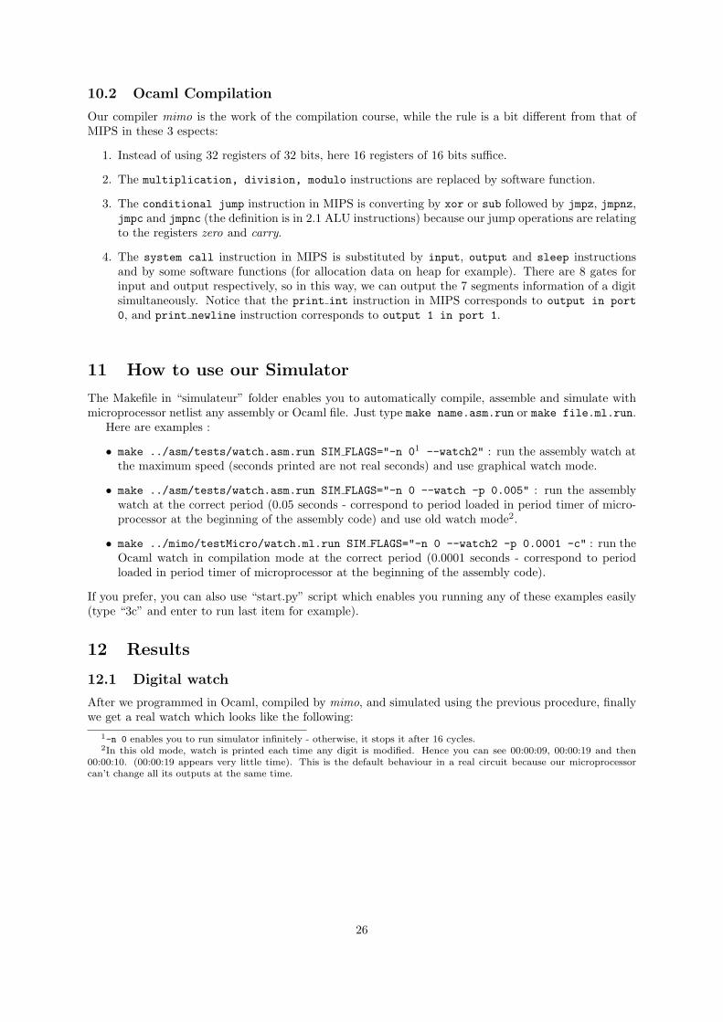
After we programmed in Ocaml, compiled by mimo, and simulated using the previous procedure, finallywe get a real watch which looks like the following:
1-n 0 enables you to run simulator infinitely - otherwise, it stops it after 16 cycles.2In this old mode, watch is printed each time any digit is modified. Hence you can see 00:00:09, 00:00:19 and then
00:00:10. (00:00:19 appears very little time). This is the default behaviour in a real circuit because our microprocessorcan’t change all its outputs at the same time.
26
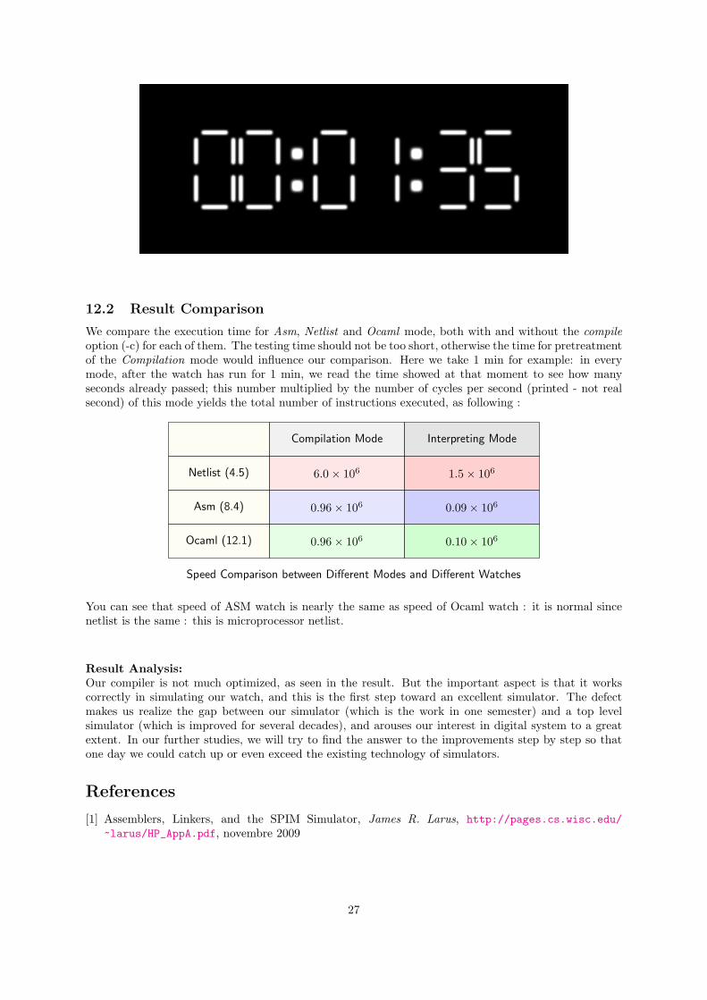
12.2 Result Comparison
We compare the execution time for Asm, Netlist and Ocaml mode, both with and without the compileoption (-c) for each of them. The testing time should not be too short, otherwise the time for pretreatmentof the Compilation mode would influence our comparison. Here we take 1 min for example: in everymode, after the watch has run for 1 min, we read the time showed at that moment to see how manyseconds already passed; this number multiplied by the number of cycles per second (printed - not realsecond) of this mode yields the total number of instructions executed, as following :
Netlist (4.5)
Asm (8.4)
Ocaml (12.1)
Compilation Mode Interpreting Mode
6.0× 10⁶ 1.5× 10⁶
0.96× 10⁶ 0.09× 10⁶
0.96× 10⁶ 0.10× 10⁶
Speed Comparison between Different Modes and Different Watches
You can see that speed of ASM watch is nearly the same as speed of Ocaml watch : it is normal sincenetlist is the same : this is microprocessor netlist.
Result Analysis:Our compiler is not much optimized, as seen in the result. But the important aspect is that it workscorrectly in simulating our watch, and this is the first step toward an excellent simulator. The defectmakes us realize the gap between our simulator (which is the work in one semester) and a top levelsimulator (which is improved for several decades), and arouses our interest in digital system to a greatextent. In our further studies, we will try to find the answer to the improvements step by step so thatone day we could catch up or even exceed the existing technology of simulators.
References
[1] Assemblers, Linkers, and the SPIM Simulator, James R. Larus, http://pages.cs.wisc.edu/
~larus/HP_AppA.pdf, novembre 2009
27