Embed Size (px)
Citation preview
DIAX03DDS02.2/03.2 Drive Controller -
Basic Unit
DOK-DIAX03-DDS02.2/3.2-PRJ1-EN-P
Project Planning Manual
mannesmannRexroth
engineering
Indramat274263

DDS02.2/03.2
DOK-DIAX03-DDS02.2/3.2-PRJ1-EN-E1,44 • 04.97
DIAX03
DDS02.2/03.2 Drive Controller -
Basic Unit
Project Planning Manual
DOK-DIAX03-DDS02.2/3.2-PRJ1-EN-E1,44 • 04.97
• Mappe 11a
• DDS_2-PJ.pdf
• 209-0075-4310-00
This electronic document based on the hardcopy document with docu-ment desig.: DOK-DIAX03-DDS02.2/3.2-PRJ1-EN-P
Document designations of previouseditions
Status Comments
DOK-DIAX03-DDS02.2/3.2-PRJ1-EN-P Jan. 97 1st releaseDDS02.2/03.2
DOK-DIAX03-DDS02.2/3.2-PRJ1-EN-E1,44 Apr. 97 First E-Doc.
INDRAMAT GmbH, 1997
Copying this document, and giving it to others and the use or communi-cation of the contents thereof without express authority, are forbidden.Offenders are liable for the payment of damages. All rights are reservedin the event of the grant of a patent or the registration of a utility model ordesign (DIN 34-1).
The electronic documentation (E-doc) may be copied as often as neededif such are to be used by the consumer for the purpose intended.
INDRAMAT GmbH • Bgm.-Dr.-Nebel-Str. 2 • D-97816 Lohr a. Main
Telefon 09352/40-0 • Tx 689421 • Fax 09352/40-4885
Abt. ENA (JH)
Service-Hotline: Tel. 0172 - 660 040 6 or 0171 - 333 882 6
All rights are reserved with respect to the content of this documentationand the availability of the product.
Title
Type of documentation
Document code
Internal file reference
Reference
Editing sequence
Copyright
Published by
Validity

DDS02.2/03.2
DOK-DIAX03-DDS02.2/3.2-PRJ1-EN-E1,44 • 04.97 Contents I
Contents
1 Introducing the system 1-11.1 Individual components of the digital AC servo drives..........................................................................1-2
1.2 Supply units for DDS02.2/03.2 drive controllers...................................................................................1-2
2 Safety guidelines for electrical drives 2-12.1 General information..............................................................................................................................2-1
2.2 Guidelines for protection against contact with electrical parts .............................................................2-2
2.3 Guidelines on "protective low voltages" ...........................................................................................2-3
2.4 Guidelines for protection against dangerous movements....................................................................2-3
2.5 Guidelines for protection when handling and installing ........................................................................2-5
3 DDS02.2/03.2 Drive Controllers 3-13.1 Configured drive controllers .................................................................................................................3-1
3.2 Drive controller - basic unit...................................................................................................................3-4
Cooling methods............................................................................................................................3-4
3.3 Software module ..................................................................................................................................3-7
Firmware........................................................................................................................................3-7
3.4 Firmware configuration.........................................................................................................................3-9
3.5 Plugin modules...................................................................................................................................3-10
3.6 Configuration Rating Plates................................................................................................................3-12
3.7 Summary of components inserted in a configuration.........................................................................3-13
4 Technical Data 4-14.1 Power section.......................................................................................................................................4-1
4.2 Current consumption of the signal processing devices........................................................................4-2
4.3 Ambient and environmental conditions ................................................................................................4-4
4.4 Drive controller energy loss..................................................................................................................4-5
Energy loss in a DDS02.2-W.........................................................................................................4-5
Energy loss in a DDS02.2-A... .......................................................................................................4-6
Energy loss in a DDS02.2-F... .......................................................................................................4-7
Energy loss in a DDS03.2-W.........................................................................................................4-8
4.5 Weight ..................................................................................................................................................4-8
5 Planning the construction of the control cabinet 5-15.1 Mounting the DDS02.2-W... drive controller.........................................................................................5-4
5.2 Mounting the DDS02.2-A... drive controller..........................................................................................5-5
5.3 Mounting the DDS02.2-F... drive controller ........................................................................................5-10
5.4 Mounting a DDS03.2-W...-. drive controller .......................................................................................5-12
5.5 Interference suppression and EMC....................................................................................................5-13
DDS02.2/03.2
DOK-DIAX03-DDS02.2/3.2-PRJ1-EN-E1,44 • 04.97 Contents II
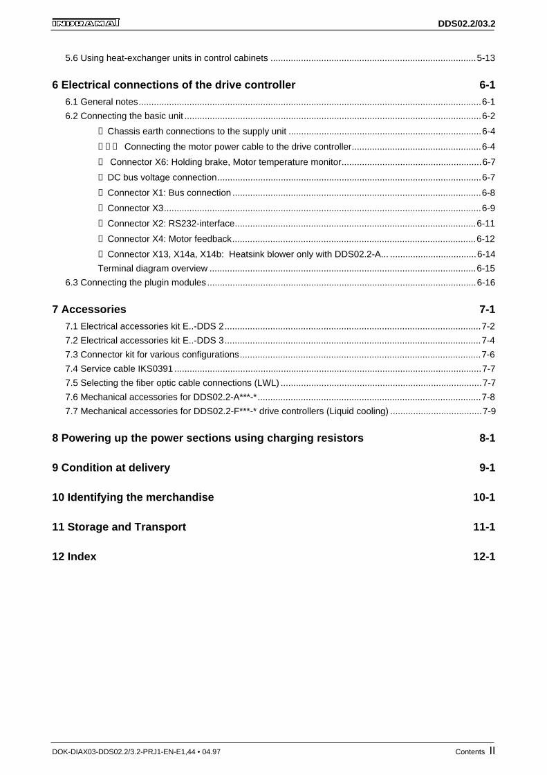
5.6 Using heat-exchanger units in control cabinets .................................................................................5-13
6 Electrical connections of the drive controller 6-16.1 General notes.......................................................................................................................................6-1
6.2 Connecting the basic unit .....................................................................................................................6-2
① Chassis earth connections to the supply unit ............................................................................6-4
②③④ Connecting the motor power cable to the drive controller...................................................6-4
④ Connector X6: Holding brake, Motor temperature monitor.......................................................6-7
⑤ DC bus voltage connection........................................................................................................6-7
⑥ Connector X1: Bus connection ..................................................................................................6-8
⑦ Connector X3.............................................................................................................................6-9
⑧ Connector X2: RS232-interface...............................................................................................6-11
⑨ Connector X4: Motor feedback................................................................................................6-12
⑩ Connector X13, X14a, X14b: Heatsink blower only with DDS02.2-A... ..................................6-14
Terminal diagram overview .........................................................................................................6-15
6.3 Connecting the plugin modules ..........................................................................................................6-16
7 Accessories 7-17.1 Electrical accessories kit E..-DDS 2.....................................................................................................7-2
7.2 Electrical accessories kit E..-DDS 3.....................................................................................................7-4
7.3 Connector kit for various configurations...............................................................................................7-6
7.4 Service cable IKS0391 .........................................................................................................................7-7
7.5 Selecting the fiber optic cable connections (LWL) ...............................................................................7-7
7.6 Mechanical accessories for DDS02.2-A***-*........................................................................................7-8
7.7 Mechanical accessories for DDS02.2-F***-* drive controllers (Liquid cooling) ....................................7-9
8 Powering up the power sections using charging resistors 8-1
9 Condition at delivery 9-1
10 Identifying the merchandise 10-1
11 Storage and Transport 11-1
12 Index 12-1
DDS02.2/03.2
DOK-DIAX03-DDS02.2/3.2-PRJ1-EN-E1,44 • 04.97 Introducing the system 1-1
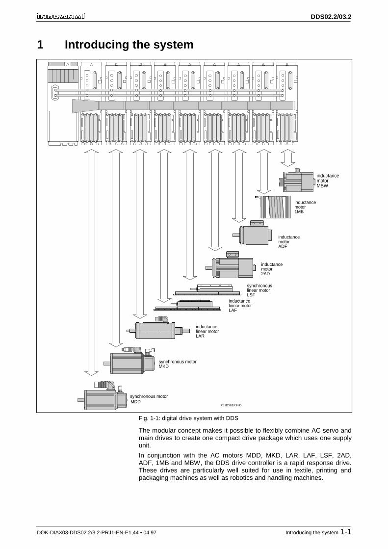
1 Introducing the system
inductancelinear motorLAR
synchronous motorMKD
MDDX01DSF1P.FH5
inductancelinear motorLAF
synchronouslinear motorLSF
inductancemotor2AD
inductancemotorADF
inductancemotor1MB
inductancemotorMBW
synchronous motor
Fig. 1-1: digital drive system with DDS
The modular concept makes it possible to flexibly combine AC servo andmain drives to create one compact drive package which uses one supplyunit.
In conjunction with the AC motors MDD, MKD, LAR, LAF, LSF, 2AD,ADF, 1MB and MBW, the DDS drive controller is a rapid response drive.These drives are particularly well suited for use in textile, printing andpackaging machines as well as robotics and handling machines.
DDS02.2/03.2
DOK-DIAX03-DDS02.2/3.2-PRJ1-EN-E1,44 • 04.97 Introducing the system 1-2
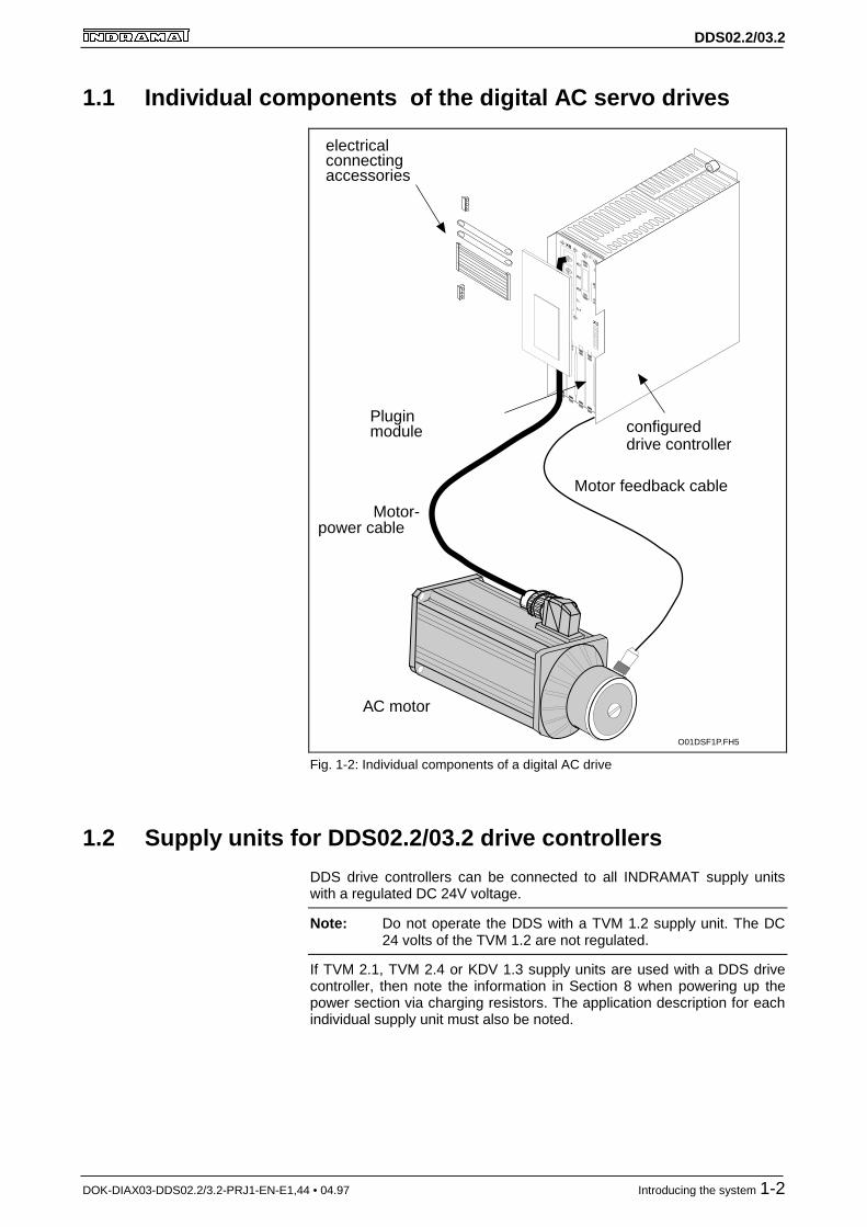
1.1 Individual components of the digital AC servo drives
O01DSF1P.FH5
L-
L+
X8
S1
1
11
A3
A1
A2
X1
configureddrive controller
electricalconnectingaccessories
Motor feedback cable
Motor-power cable
AC motor
Pluginmodule
Fig. 1-2: Individual components of a digital AC drive
1.2 Supply units for DDS02.2/03.2 drive controllers
DDS drive controllers can be connected to all INDRAMAT supply unitswith a regulated DC 24V voltage.
Note: Do not operate the DDS with a TVM 1.2 supply unit. The DC24 volts of the TVM 1.2 are not regulated.
If TVM 2.1, TVM 2.4 or KDV 1.3 supply units are used with a DDS drivecontroller, then note the information in Section 8 when powering up thepower section via charging resistors. The application description for eachindividual supply unit must also be noted.

DDS02.2/03.2
DOK-DIAX03-DDS02.2/3.2-PRJ1-EN-E1,44 • 04.97 Safety guidelines for electrical drives 2-1
2 Safety guidelines for electrical drivesPrior to using the units, please note the following guidelines on personnelsafety.
2.1 General information
• The safety instructions in these user guidelines must be observed atall times. Improper use of this equipment and disregarding the war-nings given here can lead to property damage, cause bodily injury or,in extreme cases, lead to death.
INDRAMAT is not liable for damages resulting from non-compliancewith the warning given herein.
• Documentation in the local language must be obtained prior to com-missioning, if the language of the documentation at hand is not un-derstood.
• Proper transport, correct storage, assembly and installation as well ascareful operation are the prerequisites for optimal and safe operationof this equipment.
• Qualified personnel:
Only correspondingly qualified personnel may work on this equipmentor within its vicinity. Personnel are qualified if they have sufficientknowledge of assembly, installation and operation of the product aswell as of all warnings and safety measures in these operating in-structions.
Furthermore, they should be trained, instructed or qualified to switchelectrical circuits and equipment on and off, to earth and label themaccording to safety regulations. Personnel should have adequatesafety equipment and be trained in first aid.
• Only use spare parts approved by the manufacturer.
• The safety instructions and regulations for the application must be ob-served.
• The equipment is designed for installation in machines which are in-tended for commercial use.
• Startup is only permitted once it is certain that the machine in whichthe products are installed complies with EC directive 89/392/EWG(machine directives).
• Operation is only permitted if the national EMC directives for the spe-cific application permit it. Within the EU, EMC directive 89/336/EWGapplies.
Guidelines for EMC compliant installation are outlined in the document"EMC for AC drives and controls“.
Maintaining the national standards is the responsibility of the manu-facturer of the machine or plant.
• Technical data, connection and installation conditions are outlined inthe respective product documentation and must be maintained.

DDS02.2/03.2
DOK-DIAX03-DDS02.2/3.2-PRJ1-EN-E1,44 • 04.97 Safety guidelines for electrical drives 2-2
2.2 Guidelines for protection against contact with electricalparts
If live parts with voltages exceeding 50 volts are in in any way exposedand could lead to possible contact, then this could lead to bodily injury. Tooperate electrical equipment it is necessary to apply certain parts of it withsuch dangerous voltages.
DANGER
High electrical voltage!Danger to life and risk of injury!⇒ Observe the general construction and safety guideli-
nes for work on electrical power installations.⇒ After installation, check that the earth wire is perma-
nently connected to all electrical units as specified inthe connection diagram.
⇒ Operation, even for brief measuring and test purpo-ses, is only permitted when the earth wire is perma-nently connected to all electrical components.
⇒ Disconnect the equipment from the mains or the vol-tage source before working on electrical parts withvoltage levels exceeding 50 volts. Secure the equip-ment against being switched back on.
⇒ Wait five minutes after powering down berfore startingwork on the equipment. This is due to the capacitorsfitted in the equipment.
⇒ Do not touch the electrical connecting points of acomponent while power is on.
⇒ Cover live parts properly before switching the equip-ment on so that no contact is possible.
⇒ Provide protection against indirect contact (as per DINEN 50178/ed.11.94, sect. 5.3.2.3).
WARNING
High discharge current!Danger to life and risk of serious injury!⇒ All units and the motor are to be connected to the
earth wire at the earthable point or they must beearhted first before switching on.
⇒ The discharge current exceeds 3.5 mA. A permanentconnection to the supply system is thus required for allunits (per DIN EN 50178/edition 11.94, sect. 5.3.2.3).
⇒ Always connect earth wire berfore starting up evenwhen just testing. High voltages could otherwise beapplied to the housing.

DDS02.2/03.2
DOK-DIAX03-DDS02.2/3.2-PRJ1-EN-E1,44 • 04.97 Safety guidelines for electrical drives 2-3
2.3 Guid elines on "protective low voltages"
The connections on the drive components and interfaces for the signalvoltages range from five to 30 volts. These electrical circuits belong to thesafely isolated electrical circuits (protective low voltages).
WARNING
High electrical voltage from incorrect connections!
Danger to life and limb or serious bodily injury!⇒ Only those units, electrical components or cables
which have, as per the standards, sufficient and safeisolation of connected electrical circuits may be atta-ched to the signal voltages (per DIN EN 50178/edition11.94, sect. 5.3.2.3).
2.4 Guidelines for protection against dangerous movements
Dangerous movements can occur for various reasons:
• as a result of an incorrect velocity command
• a software error
• physical component problems
• faulty wiring or cabling
• an error in the value or signal encoder and
• incorrect use of components
These errors can occur just after the equipment is turned on or after anindefinite period of time.
DDS02.2/03.2
DOK-DIAX03-DDS02.2/3.2-PRJ1-EN-E1,44 • 04.97 Safety guidelines for electrical drives 2-4
DANGER
Dangerous movements!Danger to life and risk of injury or of property damage!
⇒ The drive component moniotirng devices make mal-functions in the connected drives almost impossible.In view of operator safety, however, this cannot besolely relied upon. An incorrect movement, the size ofwhich depends on the kind of malfunction and opera-ting status, must in any case be anticipated before thebuilt-in monitoring devices are activated. Operatorsafety must thus be ensured with the use of monito-ring devices or measures taken which are superordi-nate on the plant side. These are provided, accordingto the specific conditions of the plant, after a dangerand error analysis by the plant constructor has beencompleted. The safety requirements which apply tothe plant are included here.
⇒ Keep clear of the machine in that area in which mo-vements could occur. Possible measures to take toprevent access are:- protective fences- protective railings- covers- light barriers
⇒ Fences and coverings should have sufficient strengthto withstand the maximum possible momentum.
⇒ E-stop switches must be mounted in the immediatevicinity of an operator for easy reach. Check to makesure it is functional before starting up.
⇒ Isolate the drive power connection via an emergencystop circuit or use a starting lockout to protect againstunintentioinal startups.
⇒ Make sure that the drives are standing still before ac-cessing or entering the danger zone.
⇒ De-energize electrical equipment using the masterswitch and secure against switching on again for:- maintenance and repair work- clearning work- or prior to long breaks in operation
⇒ Avoid operating high-frequency, remote-control andradio equipment near the electronics and supply lines.If use of such a unit cannot be avoided, check the sy-stem and plant for possible malfunctions at all positi-ons of general use before starting up. If necessary,carry out a special EMC test on the plant.

DDS02.2/03.2
DOK-DIAX03-DDS02.2/3.2-PRJ1-EN-E1,44 • 04.97 Safety guidelines for electrical drives 2-5
2.5 Guidelines for protection when handling and installing
CAUTION
Risk of injury during handling!Bodily injury caused by crushing, shearing, cutting and
thrusting movements is possible!
⇒ Observe the general construction and safety regulati-ons for handling and installation.
⇒ Use suitable installation and transport equipment in aproper fashion. if necessary, use special tools.
⇒ Take suitable precautions to prevent pinching andcrushing.
⇒ If necessary, wear suitable protective clothing such asprotective eyewear, shoes or gloves.
⇒ Do not stand under suspended loads.⇒ Wipe up liquids spilled onto the floor to prevent slip-
ping.

DDS02.2/03.2
DOK-DIAX03-DDS02.2/3.2-PRJ1-EN-E1,44 • 04.97 DDS02.2/03.2 Drive Controllers 3-1
3 DDS02.2/03.2 Drive Controllers
3.1 Configured drive controllers
The drive controllers are modular in design. The basic unit is adapted todifferent functions with the use of various modules. The drive controllersare delivered by INDRAMAT already configured in terms of the desiredfunction.
A configured drive controller is made up of both hardware and firmware.The firmware fixes the functions of the drive controller.
A configured drive controller is made up of:
• a drive controller - basic unit
• plugin modules
• software modules
• firmware (in software and plugin modules)
X02DSF1P.FH5
Soft-
ware-
modul
1
6
1
11
Command
communi-
cations
module
Aux.
plugin
mod.
Drive controller - basic unit
U1
U4U3
U2Hardwareconfiguration
type plate
SYSTEMCONFIGURATION
DDS02.2-W100-BE32-01-FW
DDS02.2-W100-B
DSS 02.1M
DLF 01.1M
COVER
COVER
DSM 02.3-FW
U1
U2
U3
U4
U5
265350 K47/96
FWA-DIAX03-SSE-01VRS-MS266233 K47/96
SN266233-04215 RS
Firmware configuration type plate
Type platebasic unit
DDS 02.2-W100-B K47/96
SN266233-04215 RS
S1
H1
U1 U2 U3 U4
X1
X3
X4
U5
X5
A1
L+
AchtungHier muß das
korrekteTypenschild
gemäßKonfigurationsblatt
aufgeklebt sein
ATTENTIONTHE CONFIGURATION
TYPE STICKER, WHICHIS IN ACCORDANCEWITH THE CONFIGU-
RATION SHEET, MUSTBE PLACED HERE.
U5
U4
01
2 3
45
6
78
90
1
2 3
45
6
78
9
Fig. 3-1: Components of the configured DDS02.2-*** drive controller
Configured drive controllerDDS02.2-****-****-**-FW

DDS02.2/03.2
DOK-DIAX03-DDS02.2/3.2-PRJ1-EN-E1,44 • 04.97 DDS02.2/03.2 Drive Controllers 3-2
S1
X1
X2
X4
X3
X6 1
6U5
U1 U2
H1
L-
L+
X5a
X5b
X03DSF1P.FH5
Soft-
ware
module
Command
communi-
cations
module
Drive controller basic unit
U1
Hardwareconfigurationrating plate
AchtungHier muß das
korrekteTypenschild
gemäßKonfigurationsblatt
aufgeklebt sein
ATTENTIONTHE CONFIGURATION
TYPE STICKER, WHICHIS IN ACCORDANCEWITH THE CONFIGU-
RATION SHEET, MUSTBE PLACED HERE.
SYSTEMCONFIGURATION
U1
U2
U3
U4
U5
Aux.
plugin
module
U5
265358 K47/96
FWA-DIAX03-SSE-01VRS266233 K47/96
SN266233-04214 RS
DDS03.2-W030-BE32-01-FW
DDS03.2-W030-B
DSS 02.1M
COVER
COVER
COVER
DSM 02.3-FWDDS 03.2-W030-B K47/96
SN266233-04214 RS
Firmware configuration rating plate
Rating plate -basic unit
01
2 3
45
6
78
90
1
2 3
45
6
78
9
U2
Fig. 3-2: Components of a configured DDS03.2-***
Configured drive controllerDDS03.2-****-****-**-FW

DDS02.2/03.2
DOK-DIAX03-DDS02.2/3.2-PRJ1-EN-E1,44 • 04.97 DDS02.2/03.2 Drive Controllers 3-3
T01DSF1P.FH5
Product groupDDS DDS
Line2 023 03
Version1 2
CoolingAir, control cabinet outside air (external) A 3Coolant F 3
W
Rated current
15A 015 130A 030 250A 050100A 100 3200A 200 3
Motor feedbackDigital servo feedback and BResolver feedback
Command communicationsANALOG interface AINTERBUS-S interface CSingle-axis pos. control LSERCOS interface E
Function i.d.fixed and determined by INDRAMATe.g.: 01 01
Version of function i.d.
01
FirmwareDesignation that firmware must be orderedas separate subitem.
FW
DDS XX . 2 - X XXX - X X XX - XX - FWType codes Example: 2
Comments:1 only availabile for cooling "W"2 only available for "03"3 only available for "02"
Air, control cabinet outside air (internal)
fixed and determined by INDRAMATe.g.: 01
Fig. 3-3: Type codes of a configured DDS drive controller
Type codes

DDS02.2/03.2
DOK-DIAX03-DDS02.2/3.2-PRJ1-EN-E1,44 • 04.97 DDS02.2/03.2 Drive Controllers 3-4
3.2 Drive controller - basic unit
The slots of the basic unit are empty.
Cooling methodsINDRAMAT offers various cooling methods for the DDS02.2 drive control-lers (see Fig. 3-4).
Cooling methods:
• heat technology (airflow inside the control cabinet)
• cold technology (airflow outside the control cabinet
• liquid cooling (coolant)
Units implementing heat technology dissipate heat within the control cabi-net.
Consequently:
• large control cabinet
• and/or air conditioning may be needed.
This requires the least amount of mounting and installation effort, howe-ver.
The units with cold technology and which use coolants have the advanta-ge that a large part of their heat is dissipated outside the control cabinet.As a result, they can be mounted in small cabinets or housing.
Units cooled with coolants also offer the advantage of regaining lost ener-gy.
Heat technology
Cold technology, cooling withcoolants

DDS02.2/03.2
DOK-DIAX03-DDS02.2/3.2-PRJ1-EN-E1,44 • 04.97 DDS02.2/03.2 Drive Controllers 3-5
X04DSF1P.FH5
Heat technology
Mountingpanel
Power loss
DDS 02.2 - W . . .DDS 03.2 - W . . .
DDS 02.2 - K . .
DDS 02.2 - F . . .
Power loss
Cold technology
Liquid cooling
Control cabinet back wall
Power loss
Power loss
Power loss
Mounting panel
approx. 20%
approx.80%
ap.80%
approx. 20%
Fig. 3-4: Cooling methods in DDS02.2 drive controllers
Cooling methods

DDS02.2/03.2
DOK-DIAX03-DDS02.2/3.2-PRJ1-EN-E1,44 • 04.97 DDS02.2/03.2 Drive Controllers 3-6
Fig. 3-5: Type codes of the basic DDS unit
Type codes

DDS02.2/03.2
DOK-DIAX03-DDS02.2/3.2-PRJ1-EN-E1,44 • 04.97 DDS02.2/03.2 Drive Controllers 3-7
3.3 Software module
Different functions require different software modules. The software mo-dule contains both firmware and drive parameters. The software moduleneeded depends on the selected hardware configuration and the functi-ons of the drive.
The software module guarantees that if the unit needs to be replaced, thealready entered parameters can be carried over to the new unit.
T03DSF1P.FH5
Product groupDSM DSM
Line2 = 02
Version3 = 3
Firmwaredesignation that firmware must be orderedas separate subitem = FW
Example: DSM 02 . 3 - FW
Fig. 3-6: Type codes of the software module
O02DSF1P.FH5
FWC-DIAX03-SSE-02VRS-MS266234 K35/96
DSM 2.3
DSM02.3-FW
Softwaremodule type
Serial number
Abbrev.
Firmware type
Barcode
Fig. 3-7: Rating plates on the software module
FirmwareThe functional features of the drive controllers are fixed by the firmware.
The firmware must be ordered as a separate item. This means that it isalways possible to re-order the same firmware version.
The firmware is continously being updated to function more accuratelywithout, however, changing the functions. This designation is indicated inthe type codes as the firmware release status.
If new functions are added, then the index number of the firmware versionis increased (see Fig. 3-8) .
Type codes

DDS02.2/03.2
DOK-DIAX03-DDS02.2/3.2-PRJ1-EN-E1,44 • 04.97 DDS02.2/03.2 Drive Controllers 3-8
FW C - DIAX03 - SSE - 01 V RS - MS
CategoryFirmware FW
CategoryPrint. circ.board C
Product nameProduct: DIAX03 DIAX03
Firmware type (alpha-numeric)SERCOS interface SSE
Firmware version (01...99)01 01
Character of the firmwareTest version TStandard V
Firmware release (Update)The status at time ofdelivery is the onedelivered. RS
Language (abbrev.)see INN 09.04, sect. 1-1)multilingual MS
Type codes Example:
T04DSF1P.FH5
Fig. 3-8: Firmware type codes
Type codes

DDS02.2/03.2
DOK-DIAX03-DDS02.2/3.2-PRJ1-EN-E1,44 • 04.97 DDS02.2/03.2 Drive Controllers 3-9
3.4 Firmware configuration
The firmware configuration identifies which firmware is used in a configu-red drive controller.
This means that the firmware configuration is used to determine whichfirmware the software module has, and, if applicable, which firmware is ina plugin module. The rating plate of the firmware configuration is on theface plate.
FW C - DIAX03 - SSE - 01 V RS - MS
CategoryFirmware FW
CategoryPrint. circ.board C
Product nameProduct: DIAX03 DIAX03
Firmware type (alpha-numeric)SERCOS interface SSE
Firmware version (01...99)01 01
Character of the firmwareTest version TStandard V
Firmware release (Update)The status at time ofdelivery is the onedelivered. RS
Language (abbrev.)see INN 09.04, sect. 1-1)multilingual MS
Type codes Example:
T04DSF1P.FH5
Fig. 3-9: Type codes of the firmware configuration
FWA-DIAX03-SSE-01VRS-MS K42/96269236
SN269236-02328 RS
C01DSF1P.FH5
Unit typeShipping dateweek/year
Material number
Barcode
Serial number Firmware ReleaseStatus
Fig. 3-10: Type plates for the firmware configuration

DDS02.2/03.2
DOK-DIAX03-DDS02.2/3.2-PRJ1-EN-E1,44 • 04.97 DDS02.2/03.2 Drive Controllers 3-10
3.5 Plugin modules
Only a few of the plugin modules are introduced below. The precisefunctions offered by a specific firmware version are outlined in the re-spective function description.
Type: DSS02.1M
The "SERCOS interface DSS" plugin module makes it possible to operatea digital drive with SERCOS compatible controls via a fiber optic cable. Italso offers inputs for evaluating reference switches, travel range limitswitches and sensor inputs.
Type: CLC-...
The CLC-... command card supports the central control of the drive unitsfor the implementation of an "electronic shaft".
Type: DSA01.1M
The "absolute encoder emulator" generates absolute actual position valu-es as per SSI standards (synchronous serial interface).
Type: DRF01.1M
Plugin module DRF01.1M can function in terms of either:
• an actual position detection via a resolver
or
• measuring voltages via two differential inputs
The encoder interface DAG01.2M evaluates:
• lengths and angle measuring systems with the EnDat bidirectional in-terface
• and angle measuring systems as per SSI standards
Type. DAK01.1M
The DAK01.1 is a stackable plugin module of the CLC-D02... commandcard and represents an interface to an ARCNET bus system.
Type: DEA04.2M, DEA05.2M, DEA06.2M
These plugin modules have 15 inputs and 16 outputs each via which thedrive can exchange binary signals with a PLC. They are differentiated interms of the address set.
Type: DEF01.1M
The "incremental position interface" plugin module supports the trans-mission of squarewave signals for evaluating an external measuring sy-stem directly mounted to the moving machine component in the drivecontroller.
SERCOS interface
Command card
Absolute encoder emulator
Analog signal interface
Encoder interface for encoderswith EnDat interface or
synchronous serial interface(SSI)
ARCNET coupler card
Input/outoput interface
Incremental position interface

DDS02.2/03.2
DOK-DIAX03-DDS02.2/3.2-PRJ1-EN-E1,44 • 04.97 DDS02.2/03.2 Drive Controllers 3-11
Type: DLF01.1M
The "high-resolution position interface" plugin module supports thetransmission of sinusoidal signals for evaluating an external measuringsystem directly mounted to the moving machine component in the drivecontroller.
Type: DZF02.1M
The "gearwheel encoder interface" plugin module supports the evaluationof the high-resolution main spindle position encoder.
Type: DZF03.1M
This "gearwheel encoder interface“ plugin module supports the evaluationof a gearwheel encoder (e.g., Lenord & Bauer Geber GEL244).
Note: The technical data and the terminal diagrams of the pluginmodules can be foand in the document "DIAX03 Plugin modu-les for digital intelligent drive controllers".
High-resolution positioninginterface
Gearwheel encoder interface
Gearwheel encoder interface

DDS02.2/03.2
DOK-DIAX03-DDS02.2/3.2-PRJ1-EN-E1,44 • 04.97 DDS02.2/03.2 Drive Controllers 3-12
3.6 Configuration Rating Plates
The type codes for
• the configured drive controller,
• the basic unit,
• the software module inserted in slot U5
• and the plugin modules inserted in slots U1 to U4
can be found on the rating plate.
These type codes can be used to determine which components are inwhich slots.
In the event of any problems, these type codes on the rating plate can beused to quickly order the correct replacement parts.
Note: The configuration plate supplies information about which mo-dules are in the drive controller. Please check, before startingup, that all modules are correctly in place.
Note: When mounting the drive controller, the face plate is removedfrom the controller along with the rating plate. Please make su-re that the face plate is remounted to the drive controller fromwhich it was removed.
C02DSF1P.FH5
SYSTEMCONFIGURATION
DDS 02.2-W050-BE31-01-FW
DDS 02.2-W050-B
DSS 02.1 M
DLF 01.1 M
COVER
COVER
DSM 02.3-FW
U1
U2
U3
U4
U5
269421
Slotdesignation
Type of theconfigured
drive controllerType of the
basic unit
Type of theplugin module
Type of thesoftware module
Material number ofthe
configured drive contr.
COVER = Slot in plugin module is empty
K42/96 Shipping dateweek/year
Fig. 3-11: An example of a configuration rating plate

DDS02.2/03.2
DOK-DIAX03-DDS02.2/3.2-PRJ1-EN-E1,44 • 04.97 DDS02.2/03.2 Drive Controllers 3-13
3.7 Summary of components inserted in a configuration
Use this summary to identify which plugin module ought to be in a specificdrive controller configuration.
Compare the configuration in the summary with the type of the configureddrive controller.
If the suffix of the type designation agrees with a configuration in thesummary, then the summary should list what is fitted into slots onethrough four of the basic unit.
This summary is not a selection list for available configurations.
Configuration Slot U1 Slot U2 Slot U3 Slot U4 Slot U5BE01-01-FW DSS02.1M DZF02.1M DFF01.1M CLC-D02.1M-FW DSM02.3-FW
BE01-02-FW DSS02.1M DZF02.1M DFF01.1M CLC-D02.3M-FW DSM02.3-FW
BE02-01-FW DSS02.1M DZF02.1M DFF01.1M DAG01.1M DSM02.3-FW
BE02-02-FW DSS02.1M DZF02.1M DFF01.1M DAG01.2M DSM02.3-FW
BE03-01-FW DSS02.1M DZF02.1M DAG01.1M DEA04.2M DSM02.3-FW
BE03-02-FW DSS02.1M DZF02.1M DAG01.2M DEA04.2M DSM02.3-FW
BE04-01-FW DSS02.1M DZF02.1M DAG01.1M COVER DSM02.3-FW
BE04-02-FW DSS02.1M DZF02.1M DAG01.2M COVER DSM02.3-FW
BE05-01-FW DSS02.1M DRF01.1M CLC-D02.1M-FW DAK01.1M DSM02.3-FW
BE05-02-FW DSS02.1M DRF01.1M CLC-D02.3M-FW DAK01.1M DSM02.3-FW
BE05-03-FW DSS02.1M DRF01.1M CLC-D02.3M-FW DAQ02.1M DSM02.3-FW
BE06-01-FW DSS02.1M DRF01.1M DEA04.2M COVER DSM02.3-FW
BE07-01-FW DSS02.1M DLF01.1M CLC-D02.1M-FW DAK01.1M DSM02.3-FW
BE07-02-FW DSS02.1M DLF01.1M CLC-D02.3M-FW DAK01.1M DSM02.3-FW
BE07-03-FW DSS02.1M DLF01.1M CLC-D02.3M-FW DAQ02.1M DSM02.3-FW
BE08-01-FW DSS02.1M DLF01.1M DFF01.1M COVER DSM02.3-FW
BE09-01-FW DSS02.1M DFF01.1M COVER COVER DSM02.3-FW
BE10-01-FW DSS02.1M DEA04.2M DSA01.1M COVER DSM02.3-FW
BE11-01-FW DSS02.1M DFF01.1M DEA04.2M CLC-D02.1M-FW DSM02.3-FW
BE11-02-FW DSS02.1M DFF01.1M DEA04.2M CLC-D02.3M-FW DSM02.3-FW
BE12-01-FW DSS02.1M COVER COVER COVER DSM02.3-FW
BE13-01-FW DSS02.1M DEA04.2M DFF01.1M DRF01.1M DSM02.3-FW
BE14-01-FW DSS02.1M DEA04.2M DRF01.1M CLC-D02.1M-FW DSM02.3-FW
BE14-02-FW DSS02.1M DEA04.2M DRF01.1M CLC-D02.3M-FW DSM02.3-FW
BE15-01-FW DSS02.1M DFF01.1M DRF01.1M COVER DSM02.3-FW
BE16-01-FW DSS02.1M DFF01.1M CLC-D02.1M-FW COVER DSM02.3-FW
BE16-02-FW DSS02.1M DFF01.1M CLC-D02.3M-FW COVER DSM02.3-FW
BE17-01-FW DSS02.1M DFF01.1M CLC-D02.1M-FW DAK01.1M DSM02.3-FW
BE17-02-FW DSS02.1M DFF01.1M CLC-D02.3M-FW DAQ02.1M DSM02.3-FW
BE18-01-FW DSS02.1M DRF01.1M CLC-D02.1M-FW COVER DSM02.3-FW
BE18-02-FW DSS02.1M DRF01.1M CLC-D02.3M-FW COVER DSM02.3-FW
BE20-01-FW DSS02.1M DLF01.1M DFF01.1M CLC-D02.1M-FW DSM02.3-FW
BE20-02-FW DSS02.1M DLF01.1M DFF01.1M CLC-D02.3M-FW DSM02.3-FW
BE21-01-FW DSS02.1M DLF01.1M CLC-D02.1M-FW COVER DSM02.3-FW
BE21-02-FW DSS02.1M DLF01.1M CLC-D02.3M-FW COVER DSM02.3-FW

DDS02.2/03.2
DOK-DIAX03-DDS02.2/3.2-PRJ1-EN-E1,44 • 04.97 DDS02.2/03.2 Drive Controllers 3-14
Configuration Slot U1 Slot U2 Slot U3 Slot U4 Slot U5BE22-01-FW DSS02.1M DZF02.1M DEA04.2M DFF01.1M DSM02.3-FW
BE23-01-FW DSS02.1M DEA04.2M COVER COVER DSM02.3-FW
BE24-01-FW DSS02.1M COVER DEA04.2M CLC-D02.1M-FW DSM02.3-FW
BE24-02-FW DSS02.1M COVER DEA04.2M CLC-D02.3M-FW DSM02.3-FW
BE25-01-FW DSS02.1M DEA04.2M DFF01.1M DSA01.1M DSM02.3-FW
BE27-01-FW DSS02.1M DZF02.1M DFF01.1M COVER DSM02.3-FW
BE28-01-FW DSS02.1M DLF01.1M DFF01.1M DEA04.2M DSM02.3-FW
BE29-01-FW DSS02.1M DZF02.1M CLC-D02.1M-FW COVER DSM02.3-FW
BE29-02-FW DSS02.1M DZF02.1M CLC-D02.3M-FW COVER DSM02.3-FW
BE30-01-FW DSS02.1M DFF01.1M DEA04.2M COVER DSM02.3-FW
BE31-01-FW DSS02.1M DRF01.1M COVER COVER DSM02.3-FW
BE32-01-FW DSS02.1M DLF01.1M COVER COVER DSM02.3-FW
BE33-01-FW DSS02.1M DLF01.1M DEA04.2M COVER DSM02.3-FW
BE34-01-FW DSS02.1M DLF01.1M DEA04.2M CLC-D02.1M-FW DSM02.3-FW
BE34-02-FW DSS02.1M DLF01.1M DEA04.2M CLC-D02.3M-FW DSM02.3-FW
BE35-01-FW DSS02.1M DZF02.1M CLC-D02.1M-FW DAK01.1M DSM02.3-FW
BE35-02-FW DSS02.1M DZF02.1M CLC-D02.3M-FW DAQ02.1M DSM02.3-FW
BE37-01-FW DSS02.1M DZF02.1M COVER COVER DSM02.3-FW
BE38-01-FW DSS02.1M DZF02.1M DEA04.2M COVER DSM02.3-FW
BE39-01-FW DSS02.1M DZF02.1M DEA04.2M CLC-D02.1M-FW DSM02.3-FW
BE39-02-FW DSS02.1M DZF02.1M DEA04.2M CLC-D02.3M-FW DSM02.3-FW
BE40-01-FW DSS02.1M DEA04.2M DRF01.1M DSA01.1M DSM02.3-FW
BE41-01-FW DSS02.1M CLC-D02.1M-FW COVER COVER DSM02.3-FW
BE41-02-FW DSS02.1M CLC-D02.3M-FW COVER COVER DSM02.3-FW
BE42-01-FW DSS02.1M CLC-D02.1M-FW DAK01.1M COVER DSM02.3-FW
BE42-02-FW DSS02.1M CLC-D02.3M-FW DAK01.1M COVER DSM02.3-FW
BE42-03-FW DSS02.1M COVER CLC-D02.3M-FW DAQ02.1M DSM02.3-FW
BE43-01-FW DSS02.1M DEA04.2M CLC-D02.1M-FW DAK01.1M DSM02.3-FW
BE43-02-FW DSS02.1M DEA04.2M CLC-D02.3M-FW DAQ02.1M DSM02.3-FW
BE44-01-FW DSS02.1M DFF01.1M DRF01.1M CLC-D02.1M-FW DSM02.3-FW
BE44-02-FW DSS02.1M DFF01.1M DRF01.1M CLC-D02.3M-FW DSM02.3-FW
BE45-01-FW DSS02.1M DAG01.2M COVER COVER DSM02.3-FW
BE46-01-FW DSS02.1M DEA04.2M CLC-D02.1M-FW DSA01.1M DSM02.3-FW
BE46-02-FW DSS02.1M DEA04.2M CLC-D02.3M-FW DSA01.1M DSM02.3-FW
BE47-01-FW DSS02.1M DFF01.1M DSA01.1M COVER DSM02.3-FW
BE48-01-FW DSS02.1M DFF01.1M DRF01.1M DSA01.1M DSM02.3-FW
BE49-01-FW DSS02.1M DFF01.1M CLC-D02.1M-FW DSA01.1M DSM02.3-FW
BE49-02-FW DSS02.1M DFF01.1M CLC-D02.3M-FW DSA01.1M DSM02.3-FW
BE50-01-FW DSS02.1M DRF01.1M DSA01.1M COVER DSM02.3-FW
BE51-01-FW DSS02.1M DRF01.1M CLC-D02.1M-FW DSA01.1M DSM02.3-FW
BE51-02-FW DSS02.1M DRF01.1M CLC-D02.3M-FW DSA01.1M DSM02.3-FW
BE51-03-FW DSS02.1M DRF01.1M CLC-D02.1M-FW DSA01.1M DSM02.3-FW
BE52-01-FW DSS02.1M CLC-D02.1M-FW DSA01.1M COVER DSM02.3-FW
BE52-02-FW DSS02.1M CLC-D02.3M-FW DSA01.1M COVER DSM02.3-FW
BE53-01-FW DSS02.1M CLC-D02.1M-FW DAK01.1M DSA01.1M DSM02.3-FW
BE53-02-FW DSS02.1M DSA01.1M CLC-D02.3M-FW DAQ02.1M DSM02.3-FW
BE54-01-FW DSS02.1M DSA01.1M COVER COVER DSM02.3-FW
BE55-01-FW DSS02.1M DLF01.1M DEA04.2M DSA01.1M DSM02.3-FW

DDS02.2/03.2
DOK-DIAX03-DDS02.2/3.2-PRJ1-EN-E1,44 • 04.97 DDS02.2/03.2 Drive Controllers 3-15
Configuration Slot U1 Slot U2 Slot U3 Slot U4 Slot U5BE57-01-FW DSS02.1M DLF01.1M DFF01.1M DSA01.1M DSM02.3-FW
BE61-01-FW DSS02.1M DLF01.1M CLC-D02.1M-FW DSA01.1M DSM02.3-FW
BE61-02-FW DSS02.1M DLF01.1M CLC-D02.3M-FW DSA01.1M DSM02.3-FW
BE62-01-FW DSS02.1M DLF01.1M DSA01.1M COVER DSM02.3-FW
BE63-01-FW DSS02.1M DZF02.1M DEA04.2M DSA01.1M DSM02.3-FW
BE65-01-FW DSS02.1M DZF02.1M DFF01.1M DSA01.1M DSM02.3-FW
BE69-01-FW DSS02.1M DZF02.1M CLC-D02.1M-FW DSA01.1M DSM02.3-FW
BE69-02-FW DSS02.1M DZF02.1M CLC-D02.3M-FW DSA01.1M DSM02.3-FW
BE70-01-FW DSS02.1M DZF02.1M DSA01.1M COVER DSM02.3-FW
BE71-01-FW DSS02.1M DZF02.1M DAG01.1M CLC-D02.1M-FW DSM02.3-FW
BE71-02-FW DSS02.1M DZF02.1M DAG01.2M CLC-D02.1M-FW DSM02.3-FW
BE71-03-FW DSS02.1M DZF02.1M DAG01.2M CLC-D02.3M-FW DSM02.3-FW
BE72-01-FW DSS02.1M DZF02.1M DAG01.1M DSA01.1M DSM02.3-FW
BE72-02-FW DSS02.1M DZF02.1M DAG01.2M DSA01.1M DSM02.3-FW
BE74-01-FW DSS02.1M DAG01.1M DEA04.2M COVER DSM02.3-FW
BE74-02-FW DSS02.1M DAG01.2M DEA04.2M COVER DSM02.3-FW
BE75-01-FW DSS02.1M DAG01.2M DEA04.2M CLC-D02.1M-FW DSM02.3-FW
BE75-02-FW DSS02.1M DAG01.2M DEA04.2M CLC-D02.3M-FW DSM02.3-FW
BE76-01-FW DSS02.1M DEF01.1M COVER COVER DSM02.3-FW
BE77-00-FW DSS02.1M DEF01.1M DEA04.2M CLC-D02.3M-FW DSM02.3-FW
BE78-00-FW DSS02.1M DEF01.1M DEA04.2M COVER DSM02.3-FW
BE79-01-FW DSS02.1M DZF03.1M COVER COVER DSM02.3-FW
BE80-01-FW DSS02.1M DZF03.1M DEA04.2M COVER DSM02.3-FW
BE81-00-FW DSS02.1M DEF01.1M CLC-D02.3M-FW COVER DSM02.3-FW
BE95-01-FW DSS02.1M CLC-D02.1M-FW DEA04.2M DEA05.2M DSM02.3-FW
BE95-02-FW DSS02.1M CLC-D02.3M-FW DEA04.2M DEA05.2M DSM02.3-FW
Fig. 3-12: Summary of components of the basic units inserted into different con-figurations

DDS02.2/03.2
DOK-DIAX03-DDS02.2/3.2-PRJ1-EN-E1,44 • 04.97 Technical Data 4-1
4 Technical Data
4.1 Power section
Designation Value Unit
DC bus voltage 300 +/- 15% VFig. 4-1: DC bus voltage
In the second column, the possible continuous current is listed for themaximum peak current, while the possible peak current is given for themaximum continuous current in the third column of the following list.
Drive controller Max. peak current /continuous current
Peak current / max.continuous current
DDS02.2-W015-... 15A / 15A 15A / 15A
DDS03.2-W015-... 15A / 15A 15A / 15A
DDS03.2-W030-... 30A / 12A 20A / 20A
DDS03.2-W050-... 50A / 20A 50A / 20A
DDS02.2-W050-... 50A / 50A 50A / 50A
DDS02.2-A050-... 50A / 50A 50A / 50 A
DDS02.2-F050-... 50A / 50A 50A / 50A
DDS02.2-W100-... 100A / 60A 70A / 70A
DDS02.2-A100-... 100A / 100A 100A / 100A
DDS02.2-F100-... 100A / 100A 100A / 100A
DDS02.2-W200-... 200A / 65A 90A / 90A
DDS02.2-A200-... 200A / 85A 160A / 105A
DDS02.2-F200-... 200A / 105A 200A / 105AFig. 4-2: Allocation of peak and continuous currents
DC bus voltage
Allocation of peak andcontinuous currents

DDS02.2/03.2
DOK-DIAX03-DDS02.2/3.2-PRJ1-EN-E1,44 • 04.97 Technical Data 4-2
4.2 Current consumption of the signal processing devices
The supply unit makes available DC +24V - and DC +/- 15V for all con-nected drive controllers. The sum of the current consumed by all drivecontrollers may not be permitted to exceed the current output of thesupply unit.
It generally applies to the current consumption of the drive controllers thatfor DC +/-15V, 200 mA each and for DC +24V, 1100 mA.
The current consumption for a drive unit can be determined as follows fordetailed calculations:
Current consumption of the basic unit
+ Current consumption of the plugin modules inserted in basic unit
+ Current consumption of the motor feedback (only applies if connected at X4 of the basic unit)
= Current consumption of a drive unit
Drive control-ler types
Current con-sumption DC+15V in mA
Current con-sumption DC-15V in mA
Current con-sumption DC+24V in mA
DDS02.2-... 150 150 500
DDS03.2-... 150 150 500Fig. 4-3: Current consumption of the basic unit
Use the type code of the motor to locate the designation of the motorfeedback.
Motor feed-back
Current con-sumption DC+15V in mA
Current con-sumption DC-15V in mA
Current con-sumption DC+24V in mA
G 25 5 0
K 25 5 0
L 0 0 40
M 0 0 60
S 0 0 40
T 20 0 0
6 0 0 40
7 0 0 60
L, S, 6 = digital servo feedback (DSF)M, T, 7 = digital servo feedback with multiturn absolute encoder (DSF + MTG)G = resolver feedback (RSF)K = resolver feedback with multiturn absolute encoder (RSF + MTG)
Fig. 4-4: Current consumption of the motor feedback
Note: If the designation of the motor feedback is not listed in Fig. 4-4then the current consumption of the feedback is not relevant tothe calculations.
Current consumption of thesignal processing
Current consumption of thebasic unit
Current consumption of themotor feedback
DDS02.2/03.2
DOK-DIAX03-DDS02.2/3.2-PRJ1-EN-E1,44 • 04.97 Technical Data 4-3
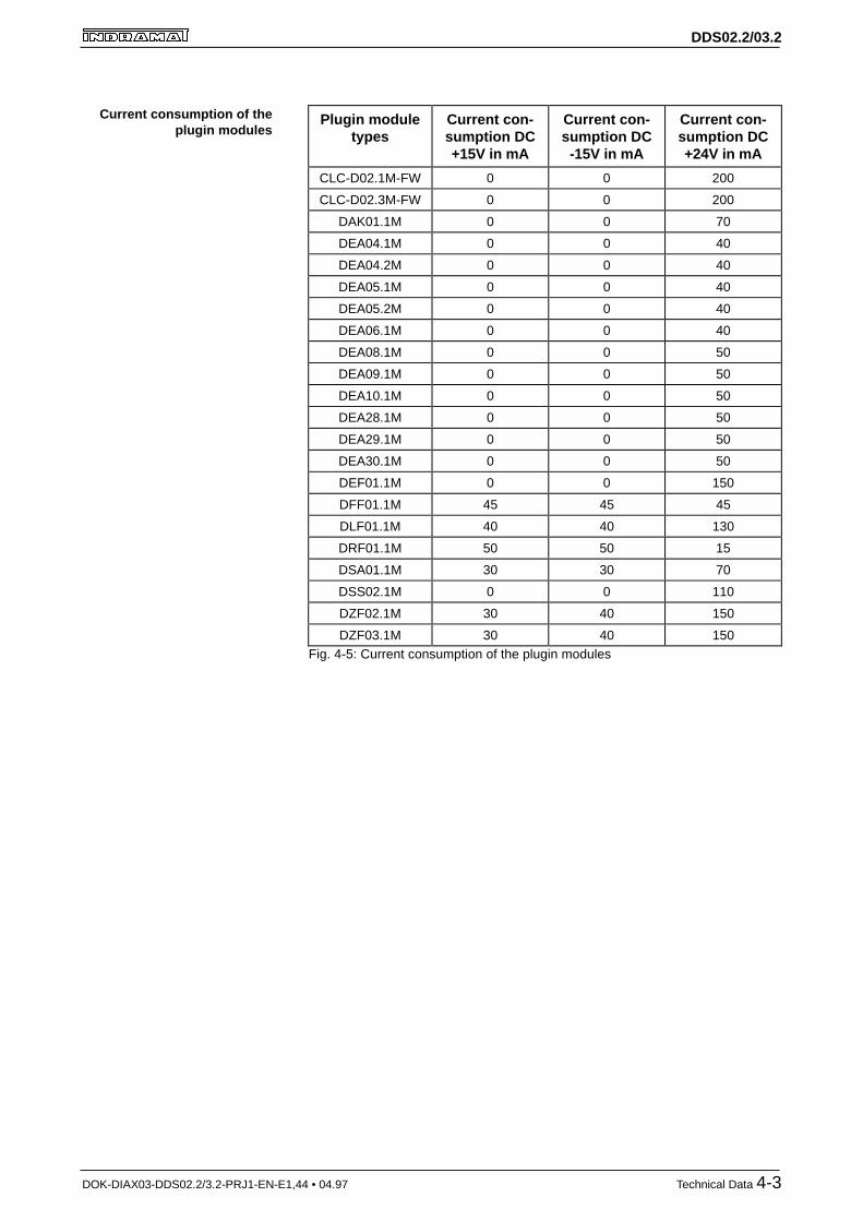
Plugin moduletypes
Current con-sumption DC+15V in mA
Current con-sumption DC-15V in mA
Current con-sumption DC+24V in mA
CLC-D02.1M-FW 0 0 200
CLC-D02.3M-FW 0 0 200
DAK01.1M 0 0 70
DEA04.1M 0 0 40
DEA04.2M 0 0 40
DEA05.1M 0 0 40
DEA05.2M 0 0 40
DEA06.1M 0 0 40
DEA08.1M 0 0 50
DEA09.1M 0 0 50
DEA10.1M 0 0 50
DEA28.1M 0 0 50
DEA29.1M 0 0 50
DEA30.1M 0 0 50
DEF01.1M 0 0 150
DFF01.1M 45 45 45
DLF01.1M 40 40 130
DRF01.1M 50 50 15
DSA01.1M 30 30 70
DSS02.1M 0 0 110
DZF02.1M 30 40 150
DZF03.1M 30 40 150Fig. 4-5: Current consumption of the plugin modules
Current consumption of theplugin modules
DDS02.2/03.2
DOK-DIAX03-DDS02.2/3.2-PRJ1-EN-E1,44 • 04.97 Technical Data 4-4
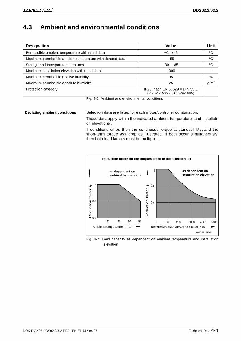
4.3 Ambient and environmental conditions
Designation Value Unit
Permissible ambient temperature with rated data +0...+45 ºC
Maximum permissible ambient temperature with derated data +55 ºC
Storage and transport temperatures -30...+85 ºC
Maximum installation elevation with rated data 1000 m
Maximum permissible relative humidity 95 %
Maximum permissible absolute humidity 25 g/m3
Protection category IP20, nach EN 60529 = DIN VDE0470-1-1992 (IEC 529-1989)
Fig. 4-6: Ambient and environmental conditions
Selection data are listed for each motor/controller combination.
These data apply within the indicated ambient temperature and installati-on elevations .
If conditions differ, then the continuous torque at standstill MdN and theshort-term torque MKB drop as illustrated. If both occur simultaneously,then both load factors must be multiplied.
as dependent onambient temperature
1
0.6
0.8
40 45 50 55
Ambient temperature in °C
Re
du
ctio
n f
acto
r f T
1
0.6
0.8
1000 2000 3000 4000
Re
du
ctio
n f
acto
r f H
5000
K01DSF1P.FH5
0
as dependent oninstallation elevation
Installation elev. above sea level in m
Reduction factor for the torques listed in the selection list
Fig. 4-7: Load capacity as dependent on ambient temperature and installationelevation
Deviating ambient conditions

DDS02.2/03.2
DOK-DIAX03-DDS02.2/3.2-PRJ1-EN-E1,44 • 04.97 Technical Data 4-5
4.4 Drive controller energy loss
Determining energy loss in the controller by adding the maximum energyloss to the controller type does not account for the actual continuous loadto the controller.
Over an average period of time, the maximum amount of the continuouscurrent at standstill IdN of the motor flows through the controller (see motordocumentation).
The actually resulting energy loss depends on the continuous current atstandstill IdN of the connected motor. The continuous current IdN at stand-still is listed in the motor documentation.
Controller: DDS 2.1 - W050 - …
Motor: MDD 093A-N-020-…
Standstill current IdN of the motor: 9.5 A
Energy loss as determined in Fig. 4-8: approx. 80 W
Energy loss in a DDS02.2-W...
600
500
400
300
200
100
1 0 2 0 3 0 4 0 5 0 6 0 7 0 8 0 9 0
380
260
110 DDS 2.2-W015-...
DDS 2.2-W050-...
DDS 2.2-W100-...Pow
er lo
ss P
v in
W
Motor cont. curr. at standstill IdN in AK02DSF1P.FH5
Controller typeDDS 2.2-W200-...
Max. power loss560
Fig. 4-8: Determining energy loss in the control cabinet
Example: determining energyloss
Energy loss in the controlcabinet

DDS02.2/03.2
DOK-DIAX03-DDS02.2/3.2-PRJ1-EN-E1,44 • 04.97 Technical Data 4-6
Energy loss in a DDS02.2-A...
120
100
80
60
40
20
2 0 4 0 6 0 8 0 1 0 0 1 2 0
Pow
er lo
ss P
v in
W
Motor cont. curr. at standstill IdN in A
K03DSF1P.FH5
Max. power loss120
Controller typeDDS 2.2-A200-...
97 DDS 2.2-A100-...
54 DDS 2.2-A050-...
Fig. 4-9: Determining energy loss in the control cabinet
500
400
300
200
100
2 0 4 0 6 0 8 0 1 0 0 1 2 0
Pow
er lo
ss P
v in
W
Motor cont. curr. at standstill IdN in A
K04DSF1P.FH5
Max. power loss477
Controller typeDDS 2.2-A200-...
380 DDS 2.2-A100-...
215 DDS 2.2-A050-...
Fig. 4-10: Determining energy loss via the heatsink and conducted outside thecontrol cabinet
Energy loss in the controlcabinet
Energy loss outside the controlcabinet

DDS02.2/03.2
DOK-DIAX03-DDS02.2/3.2-PRJ1-EN-E1,44 • 04.97 Technical Data 4-7
Energy loss in a DDS02.2-F...
120
100
80
60
40
20
2 0 4 0 6 0 8 0 1 0 0 1 2 0
Pow
er lo
ss P
v in
W
Motor cont. curr. at standstill IdN in AK05DSF1P.FH5
Max. power loss120
Controller typeDDS 2.2-F200-...
97 DDS 2.2-F100-...
54 DDS 2.2-F050-...
Fig. 4-11: Determining energy loss in the control cabinet
500
400
300
200
100
2 0 4 0 6 0 8 0 1 0 0 1 2 0
K06DSF1P.FH5
380 DDS 2.2-F100-...
215 DDS 2.2-F050-...
Pow
er lo
ss P
v in
W
Motor cont. curr. at standstill IdN in A
Max. power loss477
Controller typeDDS 2.2-F200-...
Fig. 4-12: Determining energy loss via the coolant
Energy loss in the controlcabinet
Energy loss via the coolant

DDS02.2/03.2
DOK-DIAX03-DDS02.2/3.2-PRJ1-EN-E1,44 • 04.97 Technical Data 4-8
Energy loss in a DDS03.2-W...
150
100
50
5 10 15 20
110 DDS 3.2-W030-...
Pow
er lo
ss P
v in
W
Motor cont. curr. at standstill IdN in AK07DSF1P.FH5
Controller typeDDS 3.2-W050-...
Max. power loss140
Fig. 4-13: Determining energy loss in the control cabinet
4.5 Weight
Drive controller types Weight in kg
DDS02.2-W...-. (heat technology) approx. 7.5
DDS02.2-A...-. (cold technology) approx. 11
DDS02.2-F...-. (liquid cooling) approx. 11
DDS03.2-W...-. (heat technology) approx. 5.5Fig. 4-14: Weight of the drive controller
Energy loss in the controlcabinet
DDS02.2/03.2
DOK-DIAX03-DDS02.2/3.2-PRJ1-EN-E1,44 • 04.97 Planning the construction of the control cabinet 5-1
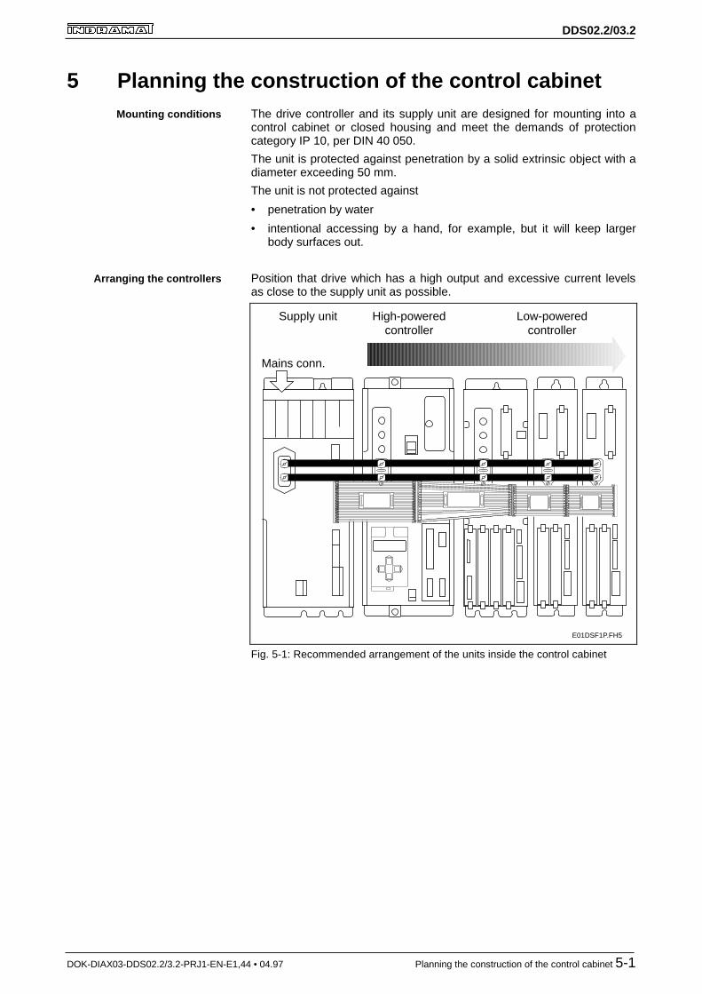
5 Planning the construction of the control cabinetThe drive controller and its supply unit are designed for mounting into acontrol cabinet or closed housing and meet the demands of protectioncategory IP 10, per DIN 40 050.
The unit is protected against penetration by a solid extrinsic object with adiameter exceeding 50 mm.
The unit is not protected against
• penetration by water
• intentional accessing by a hand, for example, but it will keep largerbody surfaces out.
Position that drive which has a high output and excessive current levelsas close to the supply unit as possible.
X5b
E01DSF1P.FH5
Supply unit High-poweredcontroller
Mains conn.
Low-poweredcontroller
ATTENTION!NEVER REMOVE OR INSTALL THISPLUGS WHILE VOLTAGE IS APPLIED.BLACK CABLE ON THE BOTTOM!Verbindung nie unter Spannunglösen bzw. stecken.Schwarze Leitung immer unten!
ATTENTION!NEVER REMOVE OR INSTALL THISPLUGS WHILE VOLTAGE IS APPLIED.BLACK CABLE ON THE BOTTOM!Verbindung nie unter Spannunglösen bzw. stecken.Schwarze Leitung immer unten!
ATTENTION!NEVER REMOVE OR INSTALL THISPLUGS WHILE VOLTAGE IS APPLIED.BLACK CABLE ON THE BOTTOM!Verbindung nie unter Spannunglösen bzw. stecken.Schwarze Leitung immer unten!
ATTENTION!NEVER REMOVE OR INSTALL THISPLUGS WHILE VOLTAGE IS APPLIED.BLACK CABLE ON THE BOTTOM!Verbindung nie unter Spannunglösen bzw. stecken.Schwarze Leitung immer unten!
Fig. 5-1: Recommended arrangement of the units inside the control cabinet
Mounting conditions
Arranging the controllers
DDS02.2/03.2
DOK-DIAX03-DDS02.2/3.2-PRJ1-EN-E1,44 • 04.97 Planning the construction of the control cabinet 5-2
110 ±0,5 110 ±0,5
TVDKDV3KDV4TVR3
DDS 2DDS 2
155 ±0,5
DDS 2
110 ±0,5 155 ±0,5
TDAKDA3.2
DDS 2
110 ±0,5 200 ±0,5
DDS 2
E02DSF1P.FH5
TVDKDV3KDV4TVR3
TVDKDV3KDV4TVR3
TVDKDV3KDV4TVR3
TDAKDA3.2
110 ±0,5
DDS 2TVM2.12.4
60
110 ±0,5
KDV2.2KDV2.3
DDS 2
110 ±0,5
KVR 1 DDS 2
110 ±0,5 110 ±0,5
KVR 1DDS 2
110 ±0,5
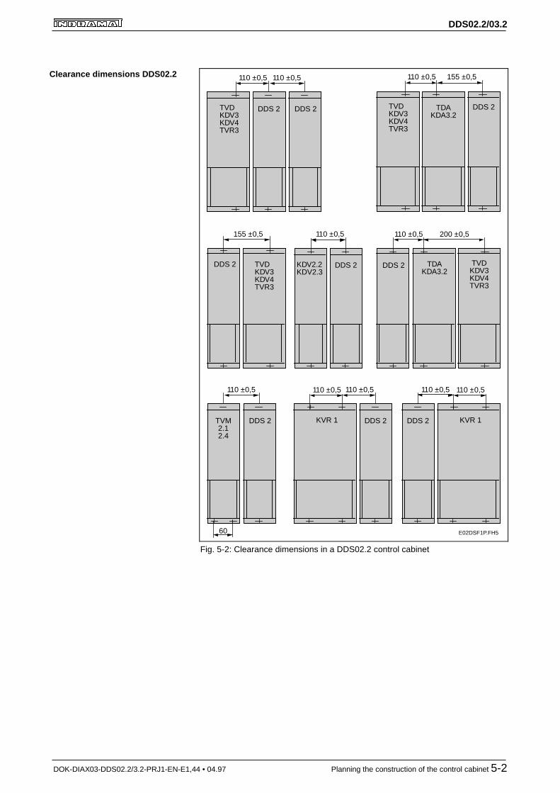
Fig. 5-2: Clearance dimensions in a DDS02.2 control cabinet
Clearance dimensions DDS02.2

DDS02.2/03.2
DOK-DIAX03-DDS02.2/3.2-PRJ1-EN-E1,44 • 04.97 Planning the construction of the control cabinet 5-3
E03DSF1P.FH5
KVR 1
110 ±0,5
DDS 3
92 ±0,5
KVR 1
110 ±0,5
DDS 3
92 ±0,5
92 ±0,5
DDS 3DDS 2
110 ±0,5 137 ±0,5
TDAKDA 3.2
TVDKDV 3KDV 4TVR 3
DDS 3
92 ±0,5 200 ±0,5
TVDKDV3KDV4TVR3
TDAKDA3.2
DDS 3
92 ±0,5
TVDKDV 3KDV 4TVR 3
DDS 3
74 ±0,5
DDS 3
155 ±0,5
TVDKDV 3KDV 4TVR 3
DDS 3
KDV2.22.3
92 ±0,5
DDS 3 TVM2.12.4
60
92 ±0,5
DDS 3
Fig. 5-3: Clearance dimensions in a DDS03.2 control cabinet
Clearance dimensions forDDS03.2

DDS02.2/03.2
DOK-DIAX03-DDS02.2/3.2-PRJ1-EN-E1,44 • 04.97 Planning the construction of the control cabinet 5-4
5.1 Mounting the DDS02.2-W... drive controller
Weight: approx. 7.5
A1 ; A2 ; A3 = M6
L- ; L+ ; PE = M5
Tighteningtorque
MA = 5 Nm
MA = 3 Nm
Connection MA
Mounting panel orcontrol
M6 machine screw (DIN 912)(Allen screw)
Allen screwdriver 906q / SW 5x400-46185Ident. no. 221 672 (avail. upon request)
105
325
min.40 mm
free
Con
tact
gua
rd
390
(18)
17
355
min
. 80
mm
min
. 80
mm
Coolinginlet
Cooling outlet
E04DSF1P.FH5
L-
L+
X8
S1
1
11
A3
A1
A2
X1
137
= =
6022.5
7
837
3
L-
L+
S1
1
11
A3
A1
A2
X1
X2
X4
X3
X6
1
6
X5
U5
U1 U3U2 U4
H1
1
8
9
15
Fig. 5-4: Dimensional sheet - DDS02.2-W... drive controller
DDS02.2/03.2
DOK-DIAX03-DDS02.2/3.2-PRJ1-EN-E1,44 • 04.97 Planning the construction of the control cabinet 5-5
5.2 Mounting the DDS02.2-A... drive controller
completely sealedhousing or cabinet
ext.
air baffle
X05DSF1P.FH5
blower
DDS2.•-A...
power loss
heatsink
exte
rn
inte
rn
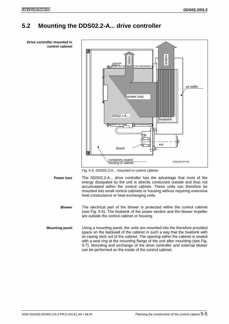
Fig. 5-5: DDS02.2-A... mounted in control cabinet
The DDS02.2-A... drive controller has the advantage that most of theenergy dissipated by the unit is directly conducted outside and thus notaccumulated within the control cabinet. These units can therefore bemounted into small control cabinets or housing without requiring extensiveheat conductance or heat exchanging units.
The electrical part of the blower is protected within the control cabinet(see Fig. 5-5). The heatsink of the power section and the blower impellerare outside the control cabinet or housing.
Using a mounting panel, the units are mounted into the therefore providedspace on the backwall of the cabinet in such a way that the heatsink withits casing stick out of the cabinet. The opening within the cabinet is sealedwith a seal ring at the mounting flange of the unit after mounting (see Fig.5-7). Mounting and exchange of the drive controller and external blowercan be performed on the inside of the control cabinet.
Drive controller mounted incontrol cabinet
Power loss
Blower
Mounting panel

DDS02.2/03.2
DOK-DIAX03-DDS02.2/3.2-PRJ1-EN-E1,44 • 04.97 Planning the construction of the control cabinet 5-6
Wei
ght:
appr
ox. 1
1
A1
; A2
; A3
= M
6
L- ;
L+ ;
PE
=
M5
Tig
hten
ing
torq
ue
MA =
5 N
m
MA =
3 N
m
Con
nect
ion
MA
Contact guard
14
355 min. 80 mmmin. 80 mm
325
min
.40
mm
free
E05
DS
F1P
.FH
5
Hea
tsin
k
1023
345
160
X13
390
S1
8 373
1 11X1
X2 X4X3
X6
1 6
X5
U5
U1
U3
U2
U4H
1
18
105
A1
A2
A3
L- L+
X14
aX
14b
915
Fig. 5-6: Dimensional sheet DDS02.2-A...
Dimensional sheet

DDS02.2/03.2
DOK-DIAX03-DDS02.2/3.2-PRJ1-EN-E1,44 • 04.97 Planning the construction of the control cabinet 5-7
Alle
n sc
rew
with
SW
5
Mak
e su
re th
at th
ere
is a
cond
uctiv
e co
nnec
tion
betw
een
the
cont
rol c
abin
et
Mac
hine
scr
ew /
4xM
4x18
Z4-
1 D
IN91
2 (1
)
Par
ts la
belle
d w
ith (
1) a
re p
art
of th
e bl
ower
uni
t.
Par
ts la
belle
d w
ith (
2) a
re p
art o
fth
e M
1-K
D a
cces
sorie
s ki
t.
blow
er 1
09-0
575-
4832
-XX
Mac
hine
scr
ew /
2xM
4x14
Z4
DIN
912
(1)
Hou
sing
bac
k w
all
Hou
sing
and
cab
inet
des
ign
Spa
ce fo
r ad
d. b
low
ers
M4
thre
ad
Blo
wer
mou
ntin
g fr
ame
(1)
Con
tact
gua
rd
KD
mod
ule
mou
ntin
g fr
ame
(2)
Air
baffl
e (1
)M
8 th
read
Spa
ce fo
r ad
d. K
D m
odul
es
Mac
hine
scr
ew /
4xM
4x16
DIN
912
(2)
(2)
M4/
4x c
onta
ct w
ashe
r
185
69
O03DSF1P.FH5
Fig. 5-7: Mounting a DDS02.2-A... drive controller
Mounting plan - DDS02.2-A...

DDS02.2/03.2
DOK-DIAX03-DDS02.2/3.2-PRJ1-EN-E1,44 • 04.97 Planning the construction of the control cabinet 5-8
E06DSF1P.FH5
KDV DDS 2.•-A...
110
min. 80min. 80
105
174
18
blower
min. 400 185
min. 2
6942
1
325
min
. 80
355
min
. 200
dismantlingdirection
completely sealedhousing or cabinet
blower mounting frame
heatsink
ext. blower
160
KD module mounting frame
air baffleDirection
ofair flow
blowermotor
DDS 2.•-A... DDS 2.•-A... DDS 2.•-A...
X15F6
X15F6
X15F6
Fig. 5-8: Installation dimensions
Installation dimensions -DDS02.2-A...

DDS02.2/03.2
DOK-DIAX03-DDS02.2/3.2-PRJ1-EN-E1,44 • 04.97 Planning the construction of the control cabinet 5-9
E07DSF1P.FH5
110±0.5 110±0.5 110±0.5
96±0.5
11
15
50+
1
9292±0.2
= =
115
133±
0.2
9
18
6 x ø5
351+
1
373±
0.2
403±
0.2
4 x ø5
= =
86+1
spacefor
DDS 2.• - A
spacefor other
units,dimensions
as with 1
View of control cabinet interior
Space for ext. blower
Fig. 5-9: Space and clearance dimensions - DDS02.2-A...
Space and clearancedimensions - DDS02.2-A...
DDS02.2/03.2
DOK-DIAX03-DDS02.2/3.2-PRJ1-EN-E1,44 • 04.97 Planning the construction of the control cabinet 5-10
5.3 Mounting the DDS02.2-F... drive controller
Mounting panel orcontrol cabinet back
M6 machine screw (DIN 912)(Allen screw)
Allen screwdriver906q / SW 5x400-46185Ident. no. 221 672(available upon request)
Weight: approx. 11
A1 ; A2 ; A3 = M6
L- ; L+ ; PE = M5
Tighteningtorque
MA = 5 Nm
MA = 3 Nm
Connection MA
Con
tact
gua
rd
(18)
17
355
min
. 80
mm
min
. 80
mm
Mountingpanel
325
75
165min.
40 mmfree
L-
L+
X8
S1
1
11
A3
A1
A2
X1
Control cabinetback wall
min.25 mm
free
E08DSF1P.FH5
390
137
= =
6022.5
S1
837
3
1
11
X1
X2
X4
X3
X6
1
6
X5
U5
U1 U3U2 U4
H1
1
8
30
105
75
125
50 11
Space forprotective
flap in mounting
150
M5
7
A1
A2
A3
L-
L+
9
15
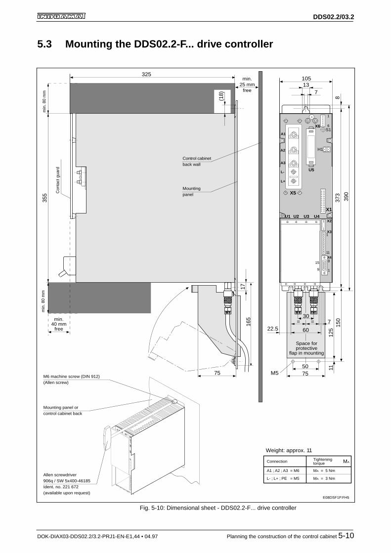
Fig. 5-10: Dimensional sheet - DDS02.2-F... drive controller

DDS02.2/03.2
DOK-DIAX03-DDS02.2/3.2-PRJ1-EN-E1,44 • 04.97 Planning the construction of the control cabinet 5-11
50
74
5.57
7082
136
15
9
Cover
2x M5x12
M01DSF1P.FH5
Fig. 5-11: Dimensional sheet of accessory kit SH-FL
Coupling
SW 19
SW 14
approx. 50
M02DSF1P.FH5
Fig. 5-12: Dimensional sheet accessory kit M2-F
Note: Please note that mounting and installation guidelines outlinedin document on "Liquid cooling Indramat drive components",(doc. no: 209-0042-4131-00).
Dimensional sheetAccessory kit SH-FL
Dimensional sheetAccessory kit M2-F

DDS02.2/03.2
DOK-DIAX03-DDS02.2/3.2-PRJ1-EN-E1,44 • 04.97 Planning the construction of the control cabinet 5-12
5.4 Mounting a DDS03.2-W...-. drive controller
Mounting panel orcontrol cabinet back
M6 machine screw (DIN 912)(Allen screw)
Allen screw driver906q / SW 5x400-46185Ident. no. 221 672(avail. upon request)
L- ; L+ ; PE = M5
Tighteningtorque
MA = 3 Nm
Connection MA
Con
tact
gua
rd
390
(18)
17
355
min
. 80
mm
min
. 80
mm
free
Mountingpanel
137
S1
837
3
1
11
A3
A2
A1
X1
X2
X4
X3
1
6U5
U1 U2
H1
1
8
325
min.40 mm
free
70
E09DSF1P.FH5
L-
L+
7
X5a
max. 4mm2
max.1.5mm2
max.1.5mm2
Cooling outlet
Cooling inlet
X5b
Weight: approx. 5.5 kg
X6
9
15
S1
1
11
A3
A1
A2
X1
Fig. 5-13: Dimensional sheet - DDS03.2-W...-.

DDS02.2/03.2
DOK-DIAX03-DDS02.2/3.2-PRJ1-EN-E1,44 • 04.97 Planning the construction of the control cabinet 5-13
5.5 Interference suppression and EMC
The mounting and installation guidelines in the Project Planning Manualon "EMC in drive and control systems" must be noted to maintain the le-gal EMC requirements.
5.6 Using heat-exchanger units in control cabinets
If heat-exchanger units are not installed and operated properly, then thedrive components inside the control cabinet could be damaged by moistu-re and condensation!
Humid air penetrates the control cabinet and, when it cools, condenseson the drive components installed.
If the heat-exchanger unit is not located properly in the control cabinet,then the water, constantly condensing on it, can drip into the installedcomponents or be sprayed onto them by the cold air current.
Proper use of heat-exchanger units:
• Only use heat-exchanger units in well-sealed control cabinets so thatmoisture cannot be brought in by any humid air from outside!
• If the control cabinets are operated with opened doors, for startup,servicing and so on, then make sure, once the doors are closed, thatthe drive components are not at any time cooler than the air in thecontrol cabinet. Condensation could otherwise occur. For this reason,the heat-exchanging unit must continue to operate even when theplant is switched off so that the temperature of the control cabinet airand the drive components installed remains at the same level.
• Set heat-exchanger units with permanent temperature adjustment to40 °C no lower!
• Position heat-exchanger units with temperature correction so that theinside temperature of the control cabinet is not lower than the outsideair temperature. Set limit to 40 °C!
Always situate heat-exchanging units so that any condensation cannotdrip into the installed drive components. Heat-exchangers on the controlcabinet roof require a special design!
Design the control cabinet in such a way that the unit blower cannot spraycondensation deposits onto the drive components after periods duringwhich the unit was not running!
• Make sure that no condensation drips from the heat-exchanger unitinto the installed drive components!
• Make sure that the temperature is correctly set on the heat-exchangerunit!
DANGER from condensation
DANGER from condense water
Avoiding condensation
Avoiding dripping and sprayingwater
Summary

DDS02.2/03.2
DOK-DIAX03-DDS02.2/3.2-PRJ1-EN-E1,44 • 04.97 Planning the construction of the control cabinet 5-14
incorrectcorrect
warm cold
heat-exch. unit
Control cabinet
warm cold
air duct
electronicunit
X06DSF1P.FH5
heat-exch. unit
electronicunit
Control cabinet
Fig. 5-14: Arranging the heat-exchanger unit on the roof of the control cabinet
X07DSF1P.FH5
Incorrect
Air outlet
Correct
air inlet
Heat-exch.unit
Airduct
electronicequipment
Control cabinet Control cabinet
air inlet
Heat-exch.unit
electronicequipment
Fig. 5-15: Arranging the heat-exchanger unit on the front of the control cabinet
Heat-exchanger unit on the roofof the control cabinet
Heat-exchanger unit on thefront of the control cabinet

DDS02.2/03.2
DOK-DIAX03-DDS02.2/3.2-PRJ1-EN-E1,44 • 04.97 Electrical connections of the drive controller 6-1
6 Electrical connections of the drive controller
6.1 General notes
• The signal lines must be routed separately of the supply lines due tointerference.
• All signal lines should use plugin clamps or D subminiature pluginconnectors to facilitate any unit replacement that might be needed.
• Analog signals must be routed via shielded leads and their shieldsmounted only to the drive controller.
• Mains, DC bus and motor leads may not be permitted to come intocontact with or be connected to the DC ±15V and DC +24V low volta-ges.
• If a high or interference voltage test of the electrical equipment of themachine is to be conducted, then all connections must be clamped offor removed entirely to avoid damage to the electronic components(permissible as per VDE 0113). The INDRAMAT drive componentsare tested in accordance with the VDE 0160 high-voltage test regulati-ons.
• Electrostatic loads endanger electronic components. Body parts thatcome into contact with these components or printed circuits, must firstbe discharged by grounding. This means that the human body must bedischarged by touching a grounded object, soldering iron and partsand tools must be placed on a conductive surface.
• Endangered components such as plugin modules must be stored ortransported in special packaging.
• Maintaining limit values for the transmission of interference (noise re-duction) at the points of connection of the machine or plant, particularlywhen operating in residential or light industrial areas, requires a shiel-ded routing of the motor power cable or the use of a shielded motorpower cable. Proper installation of an interference filter, as recom-mended by Indramat, into the mains supply conductors of the machineor plant is also advisable. The limit values as per class B (noise re-duction grade N) as per EN 55011/3.91 and table I per EN 55014/1987at the machine must be maintained. Further information can be foundin the project planning manual "EMC in drive and control systems“(Doc. no.: 209-0049-4305-..).
DDS02.2/03.2
DOK-DIAX03-DDS02.2/3.2-PRJ1-EN-E1,44 • 04.97 Electrical connections of the drive controller 6-2
6.2 Connecting the basic unit
L-
L+
S1
1
11
A3
A1
A2
X1
X2
X4
X3
X6
1
6
X5
U5
U1 U3U2 U4
H1
1
8
F01DSF1P.FH5
Motor feedback connection
RS-232 interfaceconn. for VT-100terminal or PC
Conn.motor temperature monitorMotor brake connectionExt. DC +24V conn.
Ground conn. tosupply unit
Ground conn. tomotor
Status displayerror and error messages
Fault reset key
Software moduleThree-phase current conn.of motor power cable
DC bus connectionThe connection fromadjacent unit usesconductor rails.
- drive lockout control- acknowledge drive lockout- ready- 2 analog diagnostic outputs
Bus connection toadjacent unit.The end plug insupply module conn.kit must be insertedinto the modulefurthest away.
5
2
3 1 4
6
8
7
9
ATTENTION!NEVER REMOVE OR INSTALL THISPLUGS WHILE VOLTAGE IS APPLIED.BLACK CABLE ON THE BOTTOM!Verbindung nie unter Spannunglösen bzw. stecken.Schwarze Leitung immer unten!
Blower connectiononly via DDS02.2-A...
15
9
10
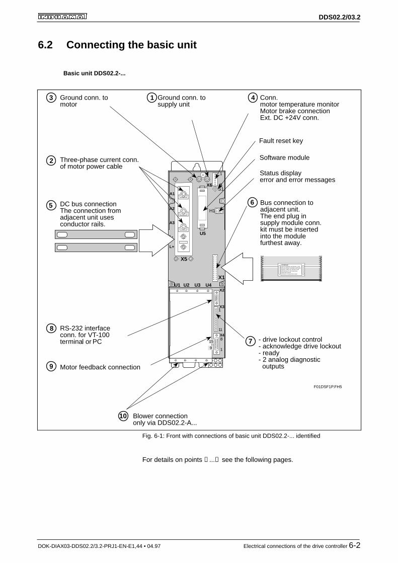
Fig. 6-1: Front with connections of basic unit DDS02.2-... identified
For details on points ①...⑩ see the following pages.
Basic unit DDS02.2-...

DDS02.2/03.2
DOK-DIAX03-DDS02.2/3.2-PRJ1-EN-E1,44 • 04.97 Electrical connections of the drive controller 6-3
S1
X1
X2
X4
X3
X6 1
6U5
U1 U2
H1
L-
L+
X5a
X5b
A3
A2
A1
F02DSF1P.FH5
5
2
3
1 4
6
8
7
ATTENTION!NEVER REMOVE OR INSTALL THISPLUGS WHILE VOLTAGE IS APPLIED.BLACK CABLE ON THE BOTTOM!Verbindung nie unter Spannunglösen bzw. stecken.Schwarze Leitung immer unten!
9
1 2 3
Motor feedback connection
RS-232 interfaceconn. for VT-100terminal or PC
Conn.motor temperature monitorMotor brake connectionExt. DC +24V conn.
Ground conn. tosupply unit
Ground conn. tomotor
Status displayerror and error messages
Fault reset key
Software module
Three-phase current conn.of motor power cable
DC bus connectionThe connection fromadjacent unit usesconductor rails.
- drive lockout control- acknowledge drive lockout- ready- 2 analog diagnostic outputs
Bus connection toadjacent unit.The end plug insupply module conn.kit must be insertedinto the modulefurthest away.
Fig. 6-2: Front with connections on basic unit DDS03.2-... identified
For details on points ①...⑩ see the following pages.
Basic unit DDS03.2-...

DDS02.2/03.2
DOK-DIAX03-DDS02.2/3.2-PRJ1-EN-E1,44 • 04.97 Electrical connections of the drive controller 6-4
①① Chassis earth connections to the supply unit
Ground connections
V01DSF1P.FH5
Fig. 6-3: Chassis earth connection to the supply module
The cross section of the chassis earth connection :
• must be as big as the cross section of the mains supply line
• not not smaller than 10 mm2
Earth loops should be avoided, if possible, as intermeshing causes inter-ference and can make fault clearance more difficult.
②②③③④④ Connecting the motor power cable to the drive controller
Use Indramat motor power cables for the lines between the drive control-ler and the AC motors.
The INDRAMAT motor power cable contains:
• three lines for the motor power connection
• one line for the protective conductor connection
• a separately shielded pair of cables for motor temperture monitoring
• a separately shielded pair of lines for the motor brake
• a total shield for power cables IKG. Applies if being operated withinresidential or light industrial areas to maintain the limit values for theemission of interference (noise reduction). Otherwise, a totally shiel-ded routing of the power supply may be necessary.
The motor power cable is a ready-made cable and available from Indra-mat. A cable can also be made out of four individual leads (three phases,one protective conductor), with a separately conducted, shielded thermalresistance and brake connection cable. for further information on techni-cal data, connections and cross sections, please check the motordescription and the cable catalog.
The maximum cable length equals 75 meters if INDRAMAT cables areused.
Core cross section
Motor power cable
Maximum cable length

DDS02.2/03.2
DOK-DIAX03-DDS02.2/3.2-PRJ1-EN-E1,44 • 04.97 Electrical connections of the drive controller 6-5
A01
DS
F1P
.FH
5
1 24 5
E H
MDDM3
A1 A3A2
A B C D
X6
Holdingbrake
F G
3 6
TM
+
TM
-
BR
0VB
UB
0VB
24VExt
0VExt 24V
PTC
U
DDS 02.2
Fig. 6-4: Motor power connection, holding brake connection and motor tempera-ture monitor with DDS02.2
S1
A3
A1
A2
X6
H1
A02DSF1P.FH5
1
2
3
4
5
6
X6Shield
U5
Motor power cable
±10%
0VExt.
24VExt.
5 or wh.
6 or br
TM+TM-
UBBR0VB0VB
7 or red
8 or bk.
1)
1)
2)
2)
1)
1)
1) The connecting cores of the motor power cable are numerically identified. Exception: the cores of cable IN 253 are color coded.
2) The external power source of the holding brake equals: 24V three-phase current ±10%. A minimum core cross section of 0.75 mm2 is recommended.
Fig. 6-5: Motor power cable connection - DDS02
Motor power connection -DDS02
Power cable connection -DDS02

DDS02.2/03.2
DOK-DIAX03-DDS02.2/3.2-PRJ1-EN-E1,44 • 04.97 Electrical connections of the drive controller 6-6
A03
DS
F1P
.FH
5
1 24 5
E H
MDD ServomotorM
3
A B C D
X6
Holdingbrake
F G
3 6
TM
+
TM
-
BR
0VB
UB
0VB
24VExt
0VExt 24V
PTC
U
DDS 03.2
1 2 X53 4
A1
A2
A3
Fig. 6-6: Motor power connection, holding brake connection and motor tempera-ture monitor - DDS03.2
S1
A3
A2
A1
1
6
U5
H1
X5a
X6
A04DSF1P.FH5
1
2
3
4
5
6
X6Shield
Motor power cable
±10%
0VExt.
24VExt.
5 or wh.
6 or br
TM+TM-
UBBR0VB0VB
7 or red
8 or bk.
1)
1)
2)
2)
1)
1)
1) The connecting cores of the motor power cable are numerically coded. Exception: the cores of cable IN 253 are color coded.
2) The external supply source of the holding brakes equals: 24V three-phase voltage ±10%. A cable cross section of at least 0.75 mm2 is recommended.
Fig. 6-7: Motor power cable connection - DDS03
In terms of the motor, the connection takes the form of either a connectoror a terminal box.
The DDS drive controller connections are outlined in the motor documen-tation as well as the circuitry with the precise clamp designations.
Motor power connection -DDS03
Power cable connection -DDS03
Motor power cable connection

DDS02.2/03.2
DOK-DIAX03-DDS02.2/3.2-PRJ1-EN-E1,44 • 04.97 Electrical connections of the drive controller 6-7
④④ Connector X6: Holding brake, Motor temperature monitor
It is only necessary to connect DC 24V if a motor holding brake is used.
The current consumption of the holding brake is listed in the motor docu-mentation.
The holding brake of MDD/MKD motors is not a service brake. It wearsdown after approximately 20,000 motor revolutions against the closedbrake disc.
Note: To release the holding brake it is necessary to apply DC +24V+/- 10 % directly to the motor. The voltage to release the motorbrake is applied at X6/3 and X6/6. It must be certain that thebrake will effectively release even if longer motor power cablesare used (the voltage drop resulting from longer motor powercables can be compensated with higher voltages (up to DC+28V) at X6/3 and X6/6).
The drive controller controls the motor holding brake.
A thermistor is connected at X6/1 and X6/2 (PTC or NTC, depending onmotor type) (see Fig. 6-6).
⑤⑤ DC bus voltage connectionAdjacent drive controllers are normally connected via the DC bus railswhich are in accessories kit E .. - DDS 2. If DC bus rails are not neededfor a specific connection, then it can be established via stranded leadsthat are as short as possible (maximum length is one meter). The crosssection of the lead depends on the supply unit or the DC bus continuousoutput.
DC bus rails must be used with the DDS02.2-.200-... .
Supply units DC bus continousoutput in kW
Line cross sectionin mm 2
TVM 1.2-... 7.5 4
TVM 2.2-.../ TVM 2.4-... 7.5 4
KDV 1.3-... 30 25
KDV 2.2-.../ KDV 2.3-... 30 25
KDV 3.1-... 30 25
KDV 4.1-... 30 25
TVD 1.2-08-3 7.5 4
TVD 1.2-15-3 15 10Fig. 6-8: DC bus connections - required cross sections
Controlling the motor holdingbrake
Motor temperature monitor

DDS02.2/03.2
DOK-DIAX03-DDS02.2/3.2-PRJ1-EN-E1,44 • 04.97 Electrical connections of the drive controller 6-8
⑥⑥ Connector X1: Bus connectionThe control electronics of the drive controllers are supplied via connectorX1. The connection starts at the supply unit and runs to the drive control-lers with the help of the bus cable. The bus cable is in kit E . . -DDS 2.Insert the cable with the black core at the bottom, into connector X1.Insert the end connector supplied in the kit (e.g.,: E3-TVD) of the supplyunit into the last unit (the unit physically furthest away from the supplyunit). In some cases, it is possible to use a special bus cable with a ma-ximum length of one meter.
E10DSF1P.FH5
Supply unitMains
L-
L+
L-
L+
End conn.
blackstrand of
busconn.cable
ATTENTION!NEVER REMOVE OR INSTALL THISPLUGS WHILE VOLTAGE IS APPLIED.BLACK CABLE ON THE BOTTOM!Verbindung nie unter Spannunglösen bzw. stecken.Schwarze Leitung immer unten!
ATTENTION!NEVER REMOVE OR INSTALL THISPLUGS WHILE VOLTAGE IS APPLIED.BLACK CABLE ON THE BOTTOM!Verbindung nie unter Spannunglösen bzw. stecken.Schwarze Leitung immer unten!
Fig. 6-9: Connecting the units via flat-ribbon cables and DC bus rails
R01DSF1P.FH5
123456789
101112
UBB+15V0V0V0V0V-15V-15V0V+24V
D
MMMM
1)1)
Bus connectionConn. X1
1)"UD" - Signal:High = DC bus voltage UD greater than permissible min. value
"BB" - Signal:High = drive module ready
Fig. 6-10: Connector assignment X1

DDS02.2/03.2
DOK-DIAX03-DDS02.2/3.2-PRJ1-EN-E1,44 • 04.97 Electrical connections of the drive controller 6-9
⑦⑦ Connector X3
R02DSF1P.FH5
X3
X3
X2
X4
1
2
3
4
5
6
7
8
9
10
11
AK1OVAK20V
BbBbAS+AS-ASQASQ
X3
M
MAnalogdiagnosticoutputs
Startinglockout
Readyto operatecontact
Fig. 6-11: Connector assignment X3
The analog diagnostic outputs are analog outputs via which drive-internalvariables are generated for test purposes, e.g., when commissioning. Forfurther details on analog diagnostics outputs, please see the applicationdescription.
Current load capacity: 4 mA
Output voltage: DC 10 V
If ready to operate contact „Bb“ closes, then the drive controller is ready toreceive power. It closes if the control voltage is on and all monitoringfunctions are signalling a ready state.
Contact „Bb“ can be evaluated in the control, for example, so that thecontrol immediately recognizes which drive controller in the drive packagehad a power failure.
Switching capacity: DC 24 V, 1 A (short-term and continuous)
Note: The direct connection of a contactor coil to the Bb contact isnot permitted as the contact could be overloaded by excessiveshort-term currents after frequent switching sequences thuscausing it to break down.
The use of varistors as protective circuits is not acceptable asthese require ever-higher levels of current over the course oftheir service life. This could cause early failures of the compo-nents and ultimately the unit as well.
Analog diagnostic outputsAK1, AK2
Ready to operate contact Bb

DDS02.2/03.2
DOK-DIAX03-DDS02.2/3.2-PRJ1-EN-E1,44 • 04.97 Electrical connections of the drive controller 6-10
The starting lockout represents a safety device to prevent unintentionalstartups of the connected motors in the event of a fault. It makes sure thatthe separately working areas of a machine or plant are securely switchedoff.
Note: The starting lockout is not intended to bring to a standstill axesthat are moving.
For further information on this subject, see the documention "Startinglockout functions in DDS drive controllers“ (Doc. no.: 209-0069-4313-XX).
AS+,AS-: control input for relay coilsvoltage: DC 20 .... 30 Vpower: 1.5 W
ASQ, ASQ: potential free response contact which acknowledges the activation of a starting lockout to an external control.Switching power: DC24V, 1A (short-term and continuous)
To activate the starting lockout, apply a voltage of DC +20 to 30V betwe-en input terminals AS+ and AS-. The switching of the startup relay in thedrive controller is confirmed by closing the potential-free response contact(output ASQ - ASQ) at the external control.
Starting lockoutAS+, AS-, ASQ, ASQ

DDS02.2/03.2
DOK-DIAX03-DDS02.2/3.2-PRJ1-EN-E1,44 • 04.97 Electrical connections of the drive controller 6-11
⑧⑧ Connector X2: RS232-interface
SignalTxDRxDRTSCTSSGND
housing
Pin23457
connector X215 pin D-subminiature conn.
SignalTxDRxDRTSCTSSGNDDTRDSR
Pin3278546
9-pin D subminiature
serial interfaceV24, RS 232C
X2
Service cable IKS0391
8
1
15
5
1
9
A05DSF1P.FH5
Order designation:
Cable Length in meters2, 5, 10 or 15m
. .
DDS 2.1
Fig. 6-12: Service cable
Service cable IKS0391 is needed to commission drive controllers withanalog interface as this interface is used for parametrization during star-tup with the use or a terminal or terminal program.
DDS02.2/03.2
DOK-DIAX03-DDS02.2/3.2-PRJ1-EN-E1,44 • 04.97 Electrical connections of the drive controller 6-12
⑨⑨ Connector X4: Motor feedback
The motor feedback is connected at X4.
The use of Indramat cables is recommended for the connections betweendrive controller and the servo motor feedback.
MDD and MKD motors are equipped with their own measuring systemwhich is connected to X4 of the basic unit.
The motors 2AD, ADF, 1MB and MBW can be equipped with their ownmeasuring system connected at X4 or a system connected at the re-spective interface plugin module. For further information, please see themotor documentation.
The linear motors LAR, LAF and LSF do not have a feedback of theirown. These motors are operated with an external system. These systemsare not connected at the X4 feedback connection of the basic unit butrather at the plugin module needed for the system. For further informati-on, see the motor documentation.
If Indramat feedback cables are used, then the maximum length equals75 meters if the connection is made at X4 of the basic unit.
If a measuring system is connected at a plugin module, however, then thelengths relevant to the plugin modules must be complied with.
For further information on INDRAMAT feedback cables, please see therelevant motor documentation.
Feedback of MDD and MKDmotors
Feedback of2AD, ADF, 1MB and MBW
motors
Feedback ofLAR, LAF and LSF motors
Maximum cable lengths

DDS02.2/03.2
DOK-DIAX03-DDS02.2/3.2-PRJ1-EN-E1,44 • 04.97 Electrical connections of the drive controller 6-13
1
8
15
7
14
SDO
SDI
SCL
FS
Dig
ital S
ervo
Fee
dbac
k
X4
10C+
3C-
9S+
2S-
40VM
12UG
9
7
4
2
3
12
8
1
5
6
10
MDDServo motor
Drivecontroller
87654321
1514131211109
X4
SDIFS
UG
C+S+
SDOSCL
0VM
C-S-Shield
R03DSF1P.FH51) Apply shield to connector housing !
1) 1)
Feedback conn. INS0513
Fig. 6-13: Connector assignment of the X4 in a DDSxx.2-xxxx-B
1
8
15
7
14
SDO
SDI
SCL
FS
Res
olve
r fe
edba
ck
X4
10S2
3S4
9S1
2S3
40VM/R3
12R1
9
7
4
2
3
12
8
1
5
6
10
MKDServo motor
Drivecontroller
87654321
1514131211109
X4
SDIFS
R1
S2S1
SDOSCL
0VM/R3S4S3Shield
R04DSF1P.FH5
1)
1) Apply shield to connector housing !
1)Feedback conn. INS0513
Fig. 6-14: Connector assignment of the X4 in a DDSxx.2-xxxx-B
Feedback connection X4 inDDSxx.2-xxxx-B for digital
servo feedback
Feedback connection X4 inDDSxx.2-xxxx-B for resolver
feedback

DDS02.2/03.2
DOK-DIAX03-DDS02.2/3.2-PRJ1-EN-E1,44 • 04.97 Electrical connections of the drive controller 6-14
⑩⑩ Connector X13, X14a, X14b: Heatsink blower only with DDS02.2-A...
Connectors X13, X14a, X14b can only be found in the DDS 2.• - A… drivecontrollers (see dimensional sheet illustration).
M
blower unitLE 4
Adjacent unit Adjacent unit
Voltage suppliedfrom adjacent unit
via cable;cable part of elec.
accessories kitE • • - DDS 2.
A06DSF1P.FH5
X13 X14b X14a
F6
L1 N
Fig. 6-15: Blower connection on the DDS02.2-A...
The DDS 2.•-A… should preferrably be connected to an adjacent unit witha 230V or 115V blower connection. If this is not possible, then a connec-tor is required (part no. 219 118). This connector will be delivered as ofcalendar week 10/95 along with the LE4 blower unit.
Type Supply voltage
in V
Frequencyin Hz
Maimum po-wer con-
sumption inVA
Fuse F6
LE4 220 AC 230 (+6/-10%) 50...60 70 0.630A/250E
LE4 115 AC 115 (±10%) 50...60 70 1.250A/250EFig. 6-16: Technical data for the LE4 blower unit
Blower Unit

DDS02.2/03.2
DOK-DIAX03-DDS02.2/3.2-PRJ1-EN-E1,44 • 04.97 Electrical connections of the drive controller 6-15
Terminal diagram overview
A07DSF1P.FH5
1
2
4
5
Drive controllerDDS 02.2 - .... - B ...
E
H
Signalprocessing(12 pin, bus cable)
X1
1 12
Additional drive modules connectedwith electrical connecting accessories
Power source ofdrive
componentsvia elec. conn.
access.
MD
D M
otor
M3
A1
A3
A2A
B
C
D
X6
Holdingbrake
F
G
Ver
sorg
ungs
mod
ul
L - L +X5
DC 300VPowervoltage
(conductor rails)
L -
L +
DC bus voltage(conductor rails)
X5
1
8
15
7
14
SDO
SDI
SCL
FS
Dig
ital S
ervo
Fee
dbac
k
X4
10C+
3C-
9S+
2S-
40VM
12UG
3
6
1
2
3
4
5
6
7
8
9
10
11
1
2
3
4
5
10
0VM
TxD TxD
RxD RxD
RTS RTS
AK1
0VM
AK2
0VM
Bb
Bb
AS+
AS-
ASQ
ASQ
X2
X3
U1
1 2 3 4-7
8,9
10 11 12
UD
BB
+ 1
5V
0VM
- 15
V
0VL
+ 2
4V
Bus connectingcable
black
X1
TM+
TM-
BR
0VB
UB
0VB
24V
Ext
0VE
xt
24V
CTS CTS
RS 232interface
U2
U3
U4Softwaremodule
U5
Analogdiagnostic
outputs
Startinglockout 9
7
4
2
3
12
8
1
5
6
10
Connection of optionalinterface module per
relevant terminal diagram.
PT
C
U
Command comm.mod.
Aux. pluginmodule
Aux. pluginmodule
Aux. pluginmodule
1) Apply shield to connector housing !
1)
1) 1)
Fig. 6-17: Terminal diagram overview for the DDS02.2-... basic unit with MDDmotor

DDS02.2/03.2
DOK-DIAX03-DDS02.2/3.2-PRJ1-EN-E1,44 • 04.97 Electrical connections of the drive controller 6-16
The complete terminal diagram overview of the DDS02.2-...-D drive con-trollers shows a MDD motor with digital servo feedback (DSF) connected(see Fig. 6-17). This diagram serves as an example for this mo-tor/controller combination.
The complete terminal diagram overview must, of course, be altered withdifferent motor/controller combinations. The drive configuration descripti-on will outline which measuring system should be connected to whichbasic unit or plugin module.
Nr. Motor Controller Difference to terminal diagram overview (see Fig. 6-17)
1 MDD with DSF andconnector
DDS02.2-....-B No difference
2 MDD with DSF andconnector
DDS03.2-....-B Slots U3 and U4 not extant
3 MDD with RSFandconnector
DDS02.2-....-B Clamp designations for X4 see Fig. 6-14
4 MDD with RSFandconnector
DDS03.2-....-B Slots U3 and U4 not extantClamp designations for X4 see Fig. 6-14
5 MKD with RSFandTerminal box
DDS02.2-....-B Clamp designations for X4 see Fig. 6-14The connections to motor feedback and motor power connection canbe found in the motor documentation
6 MKD with RSFandTerminal box
DDS03.2-....-B Clamp designations for X4 see Fig. 6-14Slots U3 and U4 not extantThe connections to motor feedback and motor power connection canbe found in the motor documentation
7 LAF DDS02.2-....-B X4 is free; Measuring system is connected to plugin module.Connection to the measuring system of motor and motor power con-nection can be found in the motor documentation
8 LAR withconnector
DDS02.2-....-B X4 is free; Measuring system is connected to plugin module.Connection to the measuring system of motor and motor power con-nection can be found in the motor documentation
9 LSF DDS02.2-....-B X4 is free; Measuring system is connected to plugin module.Connection to the measuring system of motor and motor power con-nection can be found in the motor documentation
10 2AD DDS02.2-....-B Connection to the measuring system of motor and motor power con-nection can be found in the motor documentation
11 ADF DDS02.2-....-B Connection to the measuring system of motor and motor power con-nection can be found in the motor documentation
12 1MB DDS02.2-....-B Connection to the measuring system of motor and motor power con-nection can be found in the motor documentation
13 MBW DDS02.2-....-B Connection to the measuring system of motor and motor power con-nection can be found in the motor documentation
DSF = digital servo feedback RSF = resolver feedbackFig. 6-18: Differences to the complete terminal diagram overview
6.3 Connecting the plugin modulesBoth the terminal diagrams and the technical data on the plugin modulesare outlined in the document „DIAX03 Plugin module for digital intelligentdrive controllers“.

DDS02.2/03.2
DOK-DIAX03-DDS02.2/3.2-PRJ1-EN-E1,44 • 04.97 Accessories 7-1
7 Accessories
The electrical connecting accessories kit E..-DDS.. simplies the task ofconnecting a drive package made up of various units with various alloca-tions.
To be able to select this E..-DDS.. kit, it is necessary to know the exactallocation of the units within the control cabinet.
The DDS02 drive controller generally needs an E..-DDS 2 kit.
The DDS03 generally needs the E..-DDS 3 kit.
Connector kit S..-DDS 2 is also needed. It depends on the unit configura-tion. Connector kit S..-DDS 2 can be selected for the respective configu-ration as per Fig. 8.3.
Connector kit S..-DDS 2 is identical for both the DDS02 and the DDS03.
Connection accessories E..-DDS..
Connector kit S..-DDS 2

DDS02.2/03.2
DOK-DIAX03-DDS02.2/3.2-PRJ1-EN-E1,44 • 04.97 Accessories 7-2
7.1 Electrical accessories kit E..-DDS 2
The following illustration is intended to assist in determining which E..-DDS 2 kit is needed to connect adjacent units.
Electrical connectingaccessories
for drive controller types
DDS 2.• - W
for connectingfollowing units
orientation to the right orientation to the left
E9-DDS 2E9-DDS 2E1-DDS 2E1-DDS 2E6-DDS 2E1-DDS 2E3-DDS 2E6-DDS 2E1-DDS 2
E3-DDS 2E3-DDS 2E3-DDS 2E8-DDS 2E4-DDS 2E9-DDS 2E9-DDS 2E4-DDS 2E3-DDS 2E3-DDS 2E8-DDS 2E8-DDS 2
E5-DDS 2E5-DDS 2E2-DDS 2E2-DDS 2E7-DDS 2E2-DDS 2E3-DDS 2E7-DDS 2E2-DDS 2
E3-DDS 2E3-DDS 2E3-DDS 2E10-DDS 2E5-DDS 2E5-DDS 2E5-DDS 2E5-DDS 2E3-DDS 2E3-DDS 2E10-DDS 2E10-DDS 2
KDV 1KDV 2KDV 3KDV 4KVR 1TVDTVMTVR 2TVR 3
DDS 2.• - WDDS 2.• - FDDS 2.• - ADDS 3KDAKDFKDSTDATDM 1TFMTDM 3/4TDM 6/7
Y01DSF1P.FH5
E11-DDS 2E11-DDS 2E13-DDS 2E13-DDS 2E15-DDS 2E1-DDS 2E17-DDS 2E6-DDS 2E1-DDS 2
E3-DDS 2E3-DDS 2E17-DDS 2E8-DDS 2E18-DDS 2E11-DDS 2E11-DDS 2E4-DDS 2E3-DDS 2E3-DDS 2E8-DDS 2E8-DDS 2
E12-DDS 2E12-DDS 2E14-DDS 2E14-DDS 2E16-DDS 2E2-DDS 2E17-DDS 2E7-DDS 2E2-DDS 2
E3-DDS 2E3-DDS 2E17-DDS 2E10-DDS 2E12-DDS 2E12-DDS 2E12-DDS 2E5-DDS 2E3-DDS 2E3-DDS 2E10-DDS 2E10-DDS 2
DDS 2.• - WDDS 2.• - F
Type codesType codesType codes
DDS 2.• - ADDS 2.• - WDDS 2.• - F DDS 2.• - A
The DDS 2.• - A should preferrably be connected to an adjacent unit with 220 V or 115 V blower connection.If this is not possible, then the connector 219 118 is needed for the blower connection of the DDS 2.• - A.As of 10/95, this connector will be delivered with the blower unit LE 4.
Fig. 7-1: An overview of the electrical connection accessories E..-DDS 2

DDS02.2/03.2
DOK-DIAX03-DDS02.2/3.2-PRJ1-EN-E1,44 • 04.97 Accessories 7-3
Y02DSF1P.FH5
L-
L+
S1
A3
A1
A2
X1
X2
X4
X3
X6
X5
U5
U1 U3U2 U4
H1
Connector for• motor temperature monitoring
• motor brake• external DC 24V
6-pin plugin terminal(part no. 241672)
Bus connection
Connector forI/Os
11-pin plugin terminal(Part no. 241592)
Parts forconnecting the
individualcontrollers
Power connection(DC bus rails)
Length depends on• type of adjacent unit
• distance to adjacent unit
H2
H3CHK
+UL
0VL
E4
E5
E3
E2
E1
X 1
2X
11
X 1
0S
3LO
WS
2R
XT
XH
IGH
01
2 3
45
6
78
90
1
2 3
45
6
78
9
1 2 3 4 5 6
1 2 3 4 5 6 7 8 9 10 11
ATTENTION!NEVER REMOVE OR INSTALL THISPLUGS WHILE VOLTAGE IS APPLIED.BLACK CABLE ON THE BOTTOM!Verbindung nie unter Spannunglösen bzw. stecken.Schwarze Leitung immer unten!
Power source of externalblower with DDS 2.• - A... -
units
Fig. 7-2: Components of the electrical kit E..-DDS 2

DDS02.2/03.2
DOK-DIAX03-DDS02.2/3.2-PRJ1-EN-E1,44 • 04.97 Accessories 7-4
7.2 Electrical accessories kit E..-DDS 3
The following illustration is intended to assist in determining which E..-DDS 3 kit is needed to connect adjacent units.
*)The unit to which theDDS 3 drive controlleris to be connected.
orientation to the right orientation to the left
Y03DSF1P.FH5
The electrical connectingaccessories required for
the connection
*) *)
Type codes
E10-DDS 3E10-DDS 3E1-DDS 3E1-DDS 3E7-DDS 3E1-DDS 3E3-DDS 3E1-DDS 3E7-DDS 3
E3-DDS 3E9-DDS 3E5-DDS 3E10-DDS 3E10-DDS 3E5-DDS 3E3-DDS 3E3-DDS 3E9-DDS 3E9-DDS 3
Type codes
KDV 1KDV 2KDV 3KDV 4KVR 1TVDTVMTVR 3TVR 2
DDS 2DDS 3KDAKDFKDSTDATDM 1TFMTDM 3/4TDM 6/7
DDS 3
Type codes
E6-DDS 3E6-DDS 3E2-DDS 3E2-DDS 3E8-DDS 3E2-DDS 3E4-DDS 3E2-DDS 3E8-DDS 3
E4-DDS 3E9-DDS 3E6-DDS 3E6-DDS 3E6-DDS 3E6-DDS 3E4-DDS 3E4-DDS 3E9-DDS 3E9-DDS 3
DDS 3
Fig. 7-3: A general overview of the electrical kit E..-DDS 3

DDS02.2/03.2
DOK-DIAX03-DDS02.2/3.2-PRJ1-EN-E1,44 • 04.97 Accessories 7-5
S1
X1
X2
X4
X3
X6 1
6U5
U1 U2
H1
L-
L+
X5a
X5b
Y04DSF1P.FH5
Connector for- motor temperature monitoring- motor brake- external DC 24V6-pin plugin terminal(part no. 241672)
DC bus rails
Bus
Connector forI/Os11-pin plugin terminal(part no. 241592)
Parts forconnectingindividualcontrollers
Power connection
Length depends on• type of adjacent unit
• distance to adjacent unit
Motor power connectors4-pin plugin terminal(part no. 252821)
Fig. 7-4: Components of the kit E..-DDS 3
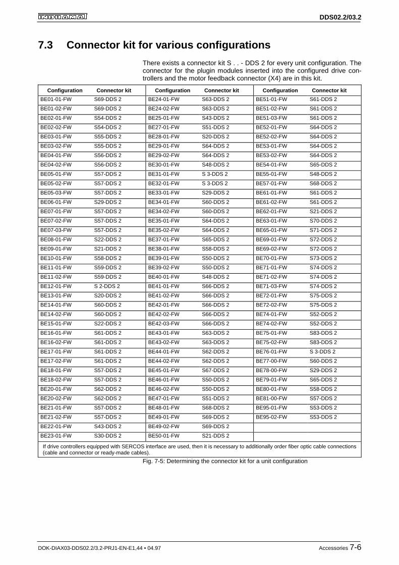
DDS02.2/03.2
DOK-DIAX03-DDS02.2/3.2-PRJ1-EN-E1,44 • 04.97 Accessories 7-6
7.3 Connector kit for various configurations
There exists a connector kit S . . - DDS 2 for every unit configuration. Theconnector for the plugin modules inserted into the configured drive con-trollers and the motor feedback connector (X4) are in this kit.
Configuration Connector kit Configuration Connector kit Configuration Connector kit
BE01-01-FW S69-DDS 2 BE24-01-FW S63-DDS 2 BE51-01-FW S61-DDS 2
BE01-02-FW S69-DDS 2 BE24-02-FW S63-DDS 2 BE51-02-FW S61-DDS 2
BE02-01-FW S54-DDS 2 BE25-01-FW S43-DDS 2 BE51-03-FW S61-DDS 2
BE02-02-FW S54-DDS 2 BE27-01-FW S51-DDS 2 BE52-01-FW S64-DDS 2
BE03-01-FW S55-DDS 2 BE28-01-FW S20-DDS 2 BE52-02-FW S64-DDS 2
BE03-02-FW S55-DDS 2 BE29-01-FW S64-DDS 2 BE53-01-FW S64-DDS 2
BE04-01-FW S56-DDS 2 BE29-02-FW S64-DDS 2 BE53-02-FW S64-DDS 2
BE04-02-FW S56-DDS 2 BE30-01-FW S48-DDS 2 BE54-01-FW S65-DDS 2
BE05-01-FW S57-DDS 2 BE31-01-FW S 3-DDS 2 BE55-01-FW S48-DDS 2
BE05-02-FW S57-DDS 2 BE32-01-FW S 3-DDS 2 BE57-01-FW S68-DDS 2
BE05-03-FW S57-DDS 2 BE33-01-FW S29-DDS 2 BE61-01-FW S61-DDS 2
BE06-01-FW S29-DDS 2 BE34-01-FW S60-DDS 2 BE61-02-FW S61-DDS 2
BE07-01-FW S57-DDS 2 BE34-02-FW S60-DDS 2 BE62-01-FW S21-DDS 2
BE07-02-FW S57-DDS 2 BE35-01-FW S64-DDS 2 BE63-01-FW S70-DDS 2
BE07-03-FW S57-DDS 2 BE35-02-FW S64-DDS 2 BE65-01-FW S71-DDS 2
BE08-01-FW S22-DDS 2 BE37-01-FW S65-DDS 2 BE69-01-FW S72-DDS 2
BE09-01-FW S21-DDS 2 BE38-01-FW S58-DDS 2 BE69-02-FW S72-DDS 2
BE10-01-FW S58-DDS 2 BE39-01-FW S50-DDS 2 BE70-01-FW S73-DDS 2
BE11-01-FW S59-DDS 2 BE39-02-FW S50-DDS 2 BE71-01-FW S74-DDS 2
BE11-02-FW S59-DDS 2 BE40-01-FW S48-DDS 2 BE71-02-FW S74-DDS 2
BE12-01-FW S 2-DDS 2 BE41-01-FW S66-DDS 2 BE71-03-FW S74-DDS 2
BE13-01-FW S20-DDS 2 BE41-02-FW S66-DDS 2 BE72-01-FW S75-DDS 2
BE14-01-FW S60-DDS 2 BE42-01-FW S66-DDS 2 BE72-02-FW S75-DDS 2
BE14-02-FW S60-DDS 2 BE42-02-FW S66-DDS 2 BE74-01-FW S52-DDS 2
BE15-01-FW S22-DDS 2 BE42-03-FW S66-DDS 2 BE74-02-FW S52-DDS 2
BE16-01-FW S61-DDS 2 BE43-01-FW S63-DDS 2 BE75-01-FW S83-DDS 2
BE16-02-FW S61-DDS 2 BE43-02-FW S63-DDS 2 BE75-02-FW S83-DDS 2
BE17-01-FW S61-DDS 2 BE44-01-FW S62-DDS 2 BE76-01-FW S 3-DDS 2
BE17-02-FW S61-DDS 2 BE44-02-FW S62-DDS 2 BE77-00-FW S60-DDS 2
BE18-01-FW S57-DDS 2 BE45-01-FW S67-DDS 2 BE78-00-FW S29-DDS 2
BE18-02-FW S57-DDS 2 BE46-01-FW S50-DDS 2 BE79-01-FW S65-DDS 2
BE20-01-FW S62-DDS 2 BE46-02-FW S50-DDS 2 BE80-01-FW S58-DDS 2
BE20-02-FW S62-DDS 2 BE47-01-FW S51-DDS 2 BE81-00-FW S57-DDS 2
BE21-01-FW S57-DDS 2 BE48-01-FW S68-DDS 2 BE95-01-FW S53-DDS 2
BE21-02-FW S57-DDS 2 BE49-01-FW S69-DDS 2 BE95-02-FW S53-DDS 2
BE22-01-FW S43-DDS 2 BE49-02-FW S69-DDS 2
BE23-01-FW S30-DDS 2 BE50-01-FW S21-DDS 2
If drive controllers equipped with SERCOS interface are used, then it is necessary to additionally order fiber optic cable connections(cable and connector or ready-made cables).
Fig. 7-5: Determining the connector kit for a unit configuration

DDS02.2/03.2
DOK-DIAX03-DDS02.2/3.2-PRJ1-EN-E1,44 • 04.97 Accessories 7-7
7.4 Service cable IKS0391
Service cable IKS0391 is needed to startup drives with ANALOG interface(see Fig. 6-12) as parametrization is conducted during startup via this in-terface using a terminal or terminal program.
7.5 Selecting the fiber optic cable connections (LWL)
The SERCOS interface implements a fiber optic cable (LWL) to commu-nicate between drive and control.
For further information on the topic "Fiber optic cable" please see theapplication description "Handling fiber optic cables" (doc. no. 209-0090-4101-xx).
In this document, the following points are discussed:
• general information about such cables
• basic planning guidelines for optical transmission systems
• routing guidelines for fiber optic cables
• attentuation measurements for ready-made fiber optic cables
• available LWL-FSMA plugin connectors and LWL cables
• how to make FSMA connectors
• tools for making LWL cables
Use the following illustration to determine the order data of the fiber opticcables for the entire system.

DDS02.2/03.2
DOK-DIAX03-DDS02.2/3.2-PRJ1-EN-E1,44 • 04.97 Accessories 7-8
1
6
DDS 2
1
11
01
2 3
45
6
78
90
1
2 3
45
6
78
9
1
6
DDS 2
1
11
01
2 3
45
6
78
90
1
2 3
45
6
78
9
1
6
DDS 2
1
11
01
2 3
45
6
78
90
1
2 3
45
6
78
9
X08DSF1P.FH5
LWL
ring
CNC
SERCOSInterface
LWL plugin coupling(control cab. leadthrough)part no. 252 524
IKO 982/ . . . depends on unit arrange.
IKO 982 / . . .
length in meters
IKO 985 / . . . /(for routing inside control cabinet)
length in meters
ø 6
mm
ø 2mm
DDS2
DDS2
orientation to the right orientation to the left*) The unit with
which the DDS 2is to be connected
with an LWLcable.
Type code
DDS 2, DDS 3
TDA
IKO 982/0,25 (239 183)
IKO 982/0,3 (239 184)
IKO 982/0,25 (239 183)
LWL cabletype (part no.)
The LWL cable for connecting
*) *)
1
6
DDS 2
1
11
01
2 3
45
6
78
90
1
2 3
45
6
78
9
LWL cabletype (part no.)
Fig. 7-6: Select the ready-made LWL cable for a SERCOS ring
7.6 Mechanical accessories for DDS02.2-A***-*
The blower unit LE4 contains those parts designated with a (1) in Fig. 5-7.
• LE4 220 for a mains voltage of AC 220V, 50...60 Hz
• LE4 115 for a mains voltage of AC 115V, 50...60 Hz
The M1-KD accessories those parts designated with a (2) in Fig. 5-7.
Blower unitLE4 220, LE4 115
Mechanical accessories kitM1-KD

DDS02.2/03.2
DOK-DIAX03-DDS02.2/3.2-PRJ1-EN-E1,44 • 04.97 Accessories 7-9
7.7 Mechanical accessories for DDS02.2-F***-* drivecontrollers (Liquid cooling)
50
74
5.57
7082
136
15
9
Cover
2x M5x12
M01DSF1P.FH5
Fig. 7-7: Dimensional sheet for accessory kit SH - FL
Coupling
SW 19
SW 14
approx. 50
M02DSF1P.FH5
Fig. 7-8: Dimensional sheet for accessory kit M2-F
Kit M2-F contains two coupling units for the liquid cooling option of a drivecontroller.
Accessory kitSH - FL
Accessory kitM2-F

DDS02.2/03.2
DOK-DIAX03-DDS02.2/3.2-PRJ1-EN-E1,44 • 04.97 Powering up the power sections using charging resistors 8-1
8 Powering up the power sections using chargingresistors
Powering up the power section via charging resistors „RL “ is an optionwhich must be selected with:
Power supply units TVM 2.1 / 2.4 - under the following conditions:
– power transformer > 10 KVA
– power transformer > 2.5 KVA and auxiliary capacitance
– no power transformer because of 220 V three-phase mains
Power supply unit KDV 1.3 - under the following conditions:
– power transformer > 50 KVA
– power transformer > 35 KVA and auxiliary capacitance
– no power transformer because of 220 V three-phase mains
Note: The Bb contact of the DDS2 drive controller closes if all moni-toring functions signal a ready state. Unlike the analog drivecontrollers TDM and KDS, the Bb contact can no longer beused to bridge the charging resistors.
Bb contact is closed with TDMand KDS drive controllers, if:
Bb contact is closed with DDSdrive controllers, if:
drive controller is ready to outputpower
DDS drive controller ready for powerto be switched on
(Bb can be used as signal to bridgethe charging resistors)
(Bb cannot be used as signal tobridge the charging resistors)
Contact „Bb“ closes if the power isswitched on and all monitoring
functions are signalling that all is inorder
Contact „Bb“ closes if the controlvoltage is switched on and all moni-toring functions are signalling that all
is in order.
Diagnosis:any unit that has failed in the drivepackage cannot be determined via
the Bb contact
Diagnosis:any unit that has failed in the drivepackage can be determined via the
Bb contact.Fig. 8-1: Comparison of ready to operate signals
Compare ready to operate

DDS02.2/03.2
DOK-DIAX03-DDS02.2/3.2-PRJ1-EN-E1,44 • 04.97 Powering up the power sections using charging resistors 8-2
K3
K1
K7
1 2
K1L1L2L3
L- L-
L+ L+
4
KDV / Bb1TVM / Bb1
K3
3
PE
DC24V
NC
K1
RF
K2
7 8
RK
R1 R3
R2 R4
K2
5 6
K2
K2
Supply unitKDV 1.3TVM 2.1
Drivecontroller
DDS 2
S3Safety
door
S1E-stop
RF inputwith ANALOG interface
(DAE 1.1 X13/4; DAA X15/4)
S2End-pos.
S5On
S4Off
Bb1 = Supply module ready (drive system)F1 = Power supply fuseK1 = Mains contactorK2 = DC bus dyn. brake contactorK3 = Release Bb1K6 = Pickup delay approx. 500 msK7 = Load contactorNC = Control error message - open with fault in drive (servo error) - closed with E-stop
RF = Control drive enable signalRK = DC bus dyn. brake resistorRL = Charging resistorS1 = E-stopS2 = End pos. of axisS3 = Safety doorsS4 = Power offS5 = Power on, reset DC bus dyn. brakeT1 = No matching transf. with 3 x AC 220 V
ATTENTION: Once K2 has been released, do not switch contactor back on for 0.5s.It mut be prevented that K2 is released and pickedup due to successive opening and closing of S2 or K3. Thiscould damage K2. Contactor K2, once switched off, may only be switched back on with a defined command (e.g.,S5).
B01DSF1P.FH5
U
Control voltage for KDV 1.3, TVM 2.1 and TVM 2.4 supply units:• with charging resistors
• with DC bus dynamic brake
K7 RLF1
L1L2L3
Control voltage
Attention : note phase coincidence!
T1
K6 K1
K6
X10/6
X10/7
K1
Fig. 8-2: Control voltage with indirect powering up of the power section via char-ging resistors in DDS drive controllers

DDS02.2/03.2
DOK-DIAX03-DDS02.2/3.2-PRJ1-EN-E1,44 • 04.97 Condition at delivery 9-1
9 Condition at deliveryThe merchandise is packed into cartons at the time of delivery. In the ca-se of individual or mixed orders (several different units), all units are pak-ked in individual one-way cartons. Accessories are in a separate carton.All individual cartons are combined in one large transport container at thetime of delivery (on a carton or pallet).
If several units are delivered, then two-way packaging can be used.
There is an envelope containing two delivery slips on the transport contai-ner. There are no other papers, unless specifically requested.
Packaging can be opened without causing damage by simply sepratingthe glued strips!

DDS02.2/03.2
DOK-DIAX03-DDS02.2/3.2-PRJ1-EN-E1,44 • 04.97 Identifying the merchandise 10-1
10 Identifying the merchandiseIn the case of a mixed order, the transport container contains the indivi-dually packaged controllers and accessories. in the case of a multiple or-der of the same units, the accessories may be placed in a separatetransport container.
There is a barcode sticker on the DDS package. It identifies the contentsin type and order processing.
C03DSF1P.FH5
Typenbezeichnung
Seriennummer des Gerätes
Positionsnummerdes Lieferscheines
DDS 02.2-W050-BE3
Made in W-GermanyGmbH Lohr/Main
Kommissionsnummer
belieferte Firma
codierteTypenbezeichnung
247204-02032
2-01-FW247204-02032
0001136672
Positionsnummerdes Lieferscheines
Kommissionsnummer
Seriennummer des Gerätes
REXROTH MECMAN
Fig. 10-1: Barcode sticker on the DDS packaging (example)
If several identical units are in one package, then the serial numbers of allthe units contained therein are under the barcode sticker (only in the caseof two-way packaging).
There is a rating plate on the front of the DDS.
C04DSF1P.FH5
Codedserialnumber
DDS 02.2-W100-B
247199-02094
Internal i.d. no.Serial number
Shippingdateweek/year
247199 K16/93
SN 247199-02094 A05
INDRAMATmaterialnumber
Typedesignation
Fig. 10-2: Rating plate on the basic DDS unit

DDS02.2/03.2
DOK-DIAX03-DDS02.2/3.2-PRJ1-EN-E1,44 • 04.97 Identifying the merchandise 10-2
The accessories are packed in bags. The order designation is written onthe bag. There is a slip in the bag which lists order number and the ac-cessory parts. In the case of ready-made cables, the order number is affi-xed to the cable. Any other types of cables have the cable number printedon them.
Page 1 Page 2
Page 3 Page 4
S1 - DDS 2
1 220623
4 221657
2 221661
1 223008
No. Designation Mat.
Delivery slip for kit S1-DDS2Z.no.:109-0852-4206-00
Date: 04.11.92Filei: S1-DDS2Mat.no. BPZ:
For unit configurations:
DA01-00DA02-00
D-SUB conn. 15 pin, bushing
D-SUB conn. 15 pin, pin
screw
housing 15 pin
plugin terminal 10 pin
1 2 3 4 5 6 7 8 9
1 241647
18915
1 89 15
G01DSF1P.FH5
250 811
Fig. 10-3: Examples of a packing slip
Accessories

DDS02.2/03.2
DOK-DIAX03-DDS02.2/3.2-PRJ1-EN-E1,44 • 04.97 Storage and Transport 11-1
11 Storage and Transport
The controllers must be stored in a dry, dust and shock free environmentwithin a permissible temperature range of -30 to +85°C.
Use shock-absorbing supports during transport, if necessary!
Transport notes found on the packaging:
G02DSF1P.FH5
AchtungHochwertige Elektronik
AttentionFragile Electronics
Vor Nässe schützenNicht belastenDo not apply loadDo not drop
Nicht werfenNicht kantenDo not tipKeep dry
Fig. 11-1: Some safety guidelines for transport

DDS02.2/03.2
DOK-DIAX03-DDS02.2/3.2-PRJ1-EN-E1,44 • 04.97 Index 12-1
12 Index
AAccessories 10-2
mechanical 7-8, 7-9
Accessory kit
M2-F 7-9
SH-FL 7-9
Ambient conditions 4-4
Ambient temperature 4-4
BBlower 5-5, 6-14
Blower Unit 6-14, 7-8
Bus cable 6-8
Bus connection 6-8
CCable length 6-4
Cable lengths 6-12
Chassis connection 6-4
Clearance dimensions
DDS02.2 5-2
DDS03.2 5-3
Condensation 5-13
Configuration Rating Plates 3-12
Configurations 3-13
Configured drive controllers 3-1
Connection accessories 7-1
Connector kit 7-1
Connectors kit 7-6
Continuous current 4-1
Current consumption 4-2
DDC bus voltage 6-7
Diagnostic outputs 6-9
Dimensional sheet
DDS02.2-A... 5-6
DDS02.2-W... 5-4
DDS03.2-W... 5-12
M2-F 5-11
SH-FL 5-11
Drive controller
coolants 3-4
cooling methods 3-5
heat technology 3-4
Drive controller - basic unit 3-4
Drive controller - cold technology 3-4
Drive controller components 3-1, 3-2
Drive controllers
Type codes 3-3, 3-6
EEMC 5-13
Energy loss 4-5
DDS02.2-A... 4-6
DDS02.2-F... 4-7
DDS02.2-W... 4-5
DDS03.2-W... 4-8
Environmental conditions 4-4
FFeedback connection 6-13
Fiber optic cables (LWL) 7-7
Firmware 3-7, 3-9
HHeat-exchanger units 5-13
Holding brake 6-7
IIndividual components 1-2
Installation elevation 4-4
Interference suppression 5-13
MMotor feedback 6-12
Motor power cable 6-4
Motor power connection 6-5, 6-6
Motor temperature monitor 6-7
Mounting conditions 5-1
Mounting panel 5-5
PPeak current 4-1
Plugin module 6-16
Plugin modules 3-10
Power loss 5-5
Power supply units 8-1
RRating plate basic unit 10-1
Ready to operate contact Bb 6-9
RS232 6-11
SSafety guidelines 2-1
Software module 3-7
Starting lockout 6-10
Storage 11-1
Supply units 1-2

DDS02.2/03.2
DOK-DIAX03-DDS02.2/3.2-PRJ1-EN-E1,44 • 04.97 Index 12-2
TTechnical Data 4-1
Terminal diagram 6-16
Transport 11-1
WWeight 4-8

DDS02.2/03.2
DOK-DIAX03-DDS02.2/3.2-PRJ1-EN-E1,44 • 04.97
Directory of Customer Service LocationsGermany
Sales region central
INDRAMAT GmbHD-97816 Lohr am MainBgm.-Dr.-Nebel-Str. 2
Telefon: 09352/40-0Telefax: 09352/40-4885
Sales region east
INDRAMAT GmbHD-09120 ChemnitzBeckerstraße 31
Telefon: 0371/3555-0Telefax: 0371/3555-230
Sales region west
INDRAMAT GmbHD-40849 RatingenHansastraße 25
Telefon: 02102/4318-0Telefax: 02102/41315
Sales region north
INDRAMAT GmbHD-22085 HamburgFährhausstraße 11
Telefon: 040/227126-16Telefax: 040/227126-15
Sales region south
INDRAMAT GmbHD-80339 MünchenRidlerstraße 75
Telefon: 089/540138-30Telefax: 089/540138-10
Sales region southwest
INDRAMAT GmbHD-71229 LeonbergBöblinger Straße 25
Telefon: 07152/972-6Telefax: 07152/972-727
INDRAMAT Service-Hotline
INDRAMAT GmbHTelefon: D-0172/660 040 6
-oder-
Telefon: D-0171/333 882 6
Customer service locations within Germany
EuropeAustria
G.L.Rexroth Ges.m.b.H.Geschäftsbereich INDRAMATA-1140 WienHägelingasse 3
Telefon: 1/9852540-400Telefax:1/9852540-93
Austria
G.L.Rexroth Ges.m.b.H.Geschäftsbereich INDRAMATA-4061 PaschingRandlstraße 14
Telefon: 07229/4401-36Telefax: 07229/4401-80
Belgium
Mannesmann Rexroth N.V.-S.A.Geschäftsbereich INDRAMATB-1740 TernatIndustrielaan 8
Telefon: 02/5823180Telefax: 02/5824310
Denmark
BEC Elektronik ASDK-8900 RandersZinkvej 6
Telefon: 086/447866Telefax: 086/447160
England
Mannesmann Rexroth Ltd.INDRAMAT DivisionCirencester, Glos GL7 1YG4 Esland Place, Love Lane
Telefon: 01285/658671Telefax: 01285/654991
Finnland
Rexroth Mecman OYSF-01720 VantaaRiihimiehentie 3
Telefon: 0/848511Telefax: 0/846387
France
Rexroth - Sigma S.A.Division INDRAMATF-92632 Gennevilliers CedexParc des Barbanniers 4,Place du Village
Telefon: 1/41475430Telefax: 1/47946941
France
Rexroth - Sigma S.A.Division INDRAMATF-69634 Venissieux - Cx91, Bd 1 Joliot Curie
Telefon: 78785256Telefax: 78785231
France
Rexroth - Sigma S.A.Division INDRAMATF-31100 Toulouse270, Avenue de lardenne
Telefon: 61499519Telefax: 61310041
Italy
Rexroth S.p.A.Divisione INDRAMATI-20063 Cernusco S/N.MIVia G. Di Vittoria, 1
Telefon: 02/92365-270Telefax: 02/92108069
Italy
Rexroth S.p.A. DivisioneINDRAMATVia Borgomanero, 11I-10145 Torino
Telefon: 011/7712230Telefax: 011/7710190
Netherlands
Hydraudyne Hydrauliek B.V.Kruisbroeksestraat 1aP.O. Box 32NL-5280 AA Boxtel
Telefon: 04116/51951Telefax: 04116/51483
Spain
Rexroth S.A.Centro Industrial SantiagoObradors s/nE-08130 Santa Perpetua de Mo-goda (Barcelona)
Telefon: 03/718 68 51Telex: 591 81Telefax: 03/718 98 62
Spain
Goimendi S.A.División IndramatJolastokieta (Herrera)Apartado 11 37San Sebastion, 20017
Telefon: 043/40 01 63Telex: 361 72Telefax: 043/39 93 95
Sweden
AB Rexroth MecmanINDRAMAT DivisionVaruvägen 7S-125 81 Stockholm
Telefon: 08/727 92 00Telefax: 08/64 73 277
Switzerland
Rexroth SADépartement INDRAMATChemin de l`Ecole 6CH-1036 Sullens
Telefon: 021/731 43 77Telefax: 021/731 46 78
Switzerland
Rexroth AGGeeschäftsbereich INDRAMATGewerbestraße 3CH-8500 Frauenfeld
Telefon: 052/720 21 00Telefax: 052/720 21 11
Russia
Tschudnenko E.B.Arsenia 22153000 IvanovoRußland
Telefon: 093/22 39 633
European customer service locations without Germany

DDS02.2/03.2
DOK-DIAX03-DDS02.2/3.2-PRJ1-EN-E1,44 • 04.97
Outside of EuropeArgentina
Mannesmann Rexroth S.A.I.C.Division INDRAMATAcassusso 48 41/71605 Munro (Buenos Aires)Argentina
Telefon: 01/756 01 40 01/756 02 40Telex: 262 66 rexro arTelefax: 01/756 01 36
Argentina
NakaseAsesoramiento TecnicoDiaz Velez 29291636 Olivos(Provincia de Buenos Aires)ArgentinaArgentina
Telefon 01/790 52 30
Australia
Australian Industrial MacheneryServices Pty. Ltd.Unit 3/45 Horne STCampbellfield VIC 2061Australia
Telefon: 03/93 59 0228Telefax: 03/93 59 02886
Brazil
Mannesmann Rexroth AutomaçãoLtda.Divisão INDRAMATRua Georg Rexroth, 609Vila Padre AnchietaBR-09.951-250 Diadema-SPCaixa Postal 377BR-09.901-970 Diadema-SP
Telefon: 011/745 90 65 011/745 90 70Telefax: 011/745 90 50
Canada
Basic Technologies CorporationBurlington Division3426 Mainway DriveBurlington, OntarioCanada L7M 1A8
Telefon: 905/335-55 11Telefax: 905/335-41 84
China
Rexroth (China) Ldt.Shanghai OfficeRoom 206Shanghai Intern. Trade Centre2200 Yanan Xi LuShanghai 200335P.R. China
Telefon: 021/627 55 333Telefax: 021/627 55 666
China
Rexroth (China) Ldt.Shanghai Parts & Service Centre199 Wu Cao Road, Hua CaoMinhang DistrictShanghai 201 103P.R. China
Telefon: 021/622 00 058Telefax: 021/622 00 068
China
Rexroth (China) Ldt.1430 China World Trade Centre1, Jianguomenwai AvenueBeijing 100004P.R. China
Telefon: 010/50 50 380Telefax: 010/50 50 379
China
Rexroth (China) Ldt.A-5F., 123 Lian Shan StreetSha He Kou DistrictDalian 116 023P.R. China
Telefon: 0411/46 78 930Telefax: 0411/46 78 932
Honkong
Rexroth (China) Ldt.19 Cheung Shun Street1st Floor, Cheung Sha Wan,Kowloon, Honkong
Telefon: 741 13 51/-54 and 741 14 30Telex: 3346 17 GL REX HXTelefax: 786 40 19 786 07 33
India
Mannesmann Rexroth (India) Ltd.INDRAMAT DivisionPlot. 96, Phase IIIPeenya Industrial AreaBangalore - 560058
Telefon: 80/839 21 01 80/839 73 74Telex: 845 5028 RexBTelefax: 80/839 43 45
Japan
Rexroth Co., Ltd.INDRAMAT DivisionI.R. BuildingNakamachidai 4-26-44Tsuzuki-ku, Yokohama 226Japan
Telefon: 045/942-72 10Telefax: 045/942-03 41
Korea
Rexroth-Seki Co Ltd.1500-12 Da-Dae-DongSaha-Gu, Pusan, 604-050
Telefon: 051/264 90 01Telefax: 051/264 90 10
Korea
Seo Chang Corporation Ltd.Room 903, Jeail Building44-35 Yoido-DongYoungdeungpo-KuSeoul, Korea
Telefon: 02/780-82 07 ~9Telefax: 02/784-54 08
Mexico
Motorización yDiseño de Controles, S.A. de C.V.Av. Dr. Gustavo Baz No. 288Col. Parque Industrial la IomaApartado Postal No. 31854060 TlalnepantlaEstado de Mexico
Telefon: 5/397 86 44Telefax: 5/398 98 88
USA
Rexroth CorporationINDRAMAT Division5150 Prairie Stone ParkwayHoffman Estates, Illinois 60192
Telefon: 847/645-36 00Telefax: 857/645-62 01
USA
Rexroth CorporationINDRAMAT Division2110 Austin AvenueRochester Hills, Michigan 48309
Telefon: 810/853-82 90Telefax: 810/853-82 90
Customer service locations outside of Europe

Indramat


![[창업에듀]03.2 비즈니스 모델 생산관리 프로세스 바로 알기](https://img.dokumen.tips/doc/110x75/58d0d0001a28ab47238b4625/032-58d0d0001a28ab47238b4625.jpg)
![[03.2] cobit y el gobierno de ti](https://img.dokumen.tips/doc/110x75/55aaa4e21a28ab693e8b4774/032-cobit-y-el-gobierno-de-ti.jpg)