Embed Size (px)
Citation preview
DulcoFlex DFB SERIES INSTRUCTION MANUAL 04.13 P/N 7500777 Rev. C
1
INSTRUCTION MANUAL
DFB 10, DFB 13, DFB 16, DFB 19, DFB 22 This manual forms an integral part of the pump and must accompany it until its demolition. The series DFBu peristaltic pump is a machine destined to work in industrial areas and as such the instruction manual must form part of the legislative dispositions and the applicable technical standards and does not substitute any installation standard or eventual additional standard.
The person in charge of safety should therefore guarantee that: -‐ The pump is transported, installed, put in service, used, maintained and repaired by qualified personnel who should possess: -‐ Specific training and sufficient experience. -‐ Knowledge of the technical standards and applicable laws. -‐ Knowledge of the general national and local safety standards and also of installation. Any work carried out on the electrical part of the pump should be authorized by the person responsible for safety. Given that the pump is destined to form part of an installation, it is the responsibility of whoever supervises the installation to guarantee absolute safety, adopting the necessary measures of additional protection.
GENERAL SAFETY WARNING
Pumps are machines that operate under pressure and have numerous moving parts. - Improper use - Removing the protections and/or disconnecting the protection device - Lack of inspections and maintenance
CAN CAUSE SERIOUS DAMAGE OR INJURY

DulcoFlex DFB SERIES INSTRUCTION MANUAL 04.13 P/N 7500777 Rev. C
2
INDEX
Page # Cover
01
Index
02
IdentCode
03
Transport, and Storage
04
General Safety Standards
05
General Description
07
Installation
08
Roller Pressure Adjustment
09
Operating Conditions
10
Performance Curves
10
Checks Before Starting the Pump
11
Maintenance
12
Removing the Hose – Disassembly
12
Installing the Hose – Assembly
12
Problems, Causes and Solutions
13
Diagram of Components Parts
14
Spare Parts List
15
Warranty
16

DulcoFlex DFB SERIES INSTRUCTION MANUAL 04.13 P/N 7500777 Rev. C
3

DulcoFlex DFB SERIES INSTRUCTION MANUAL 04.13 P/N 7500777 Rev. C
4
TRANSPORT and STORAGE
TRANSPORT • The pump is protected by cardboard packaging. • The packaging materials are recyclable.
STORAGE
• Avoid areas open to inclement weather or excessive humidity. • For storage periods of longer than 60 days, protect the coupling surfaces ( clamps,
reducers, motors ) with adequate anti-‐oxidant products. • Spare tubes should be stored in a dry place away from the direct light.

DulcoFlex DFB SERIES INSTRUCTION MANUAL 04.13 P/N 7500777 Rev. C
5
GENERAL SAFETY STANDARDS
• Instructions of this manual that may compromise safety
standards are identified by this symbol.
• Instructions of this manual that may compromise electrical safety are identified by this symbol.
• Instructions of this manual that may compromise the proper operation of the pump are identified with this symbol.
Do not start the pump without first having installed the front cover.
For any operation of the equipment, it is necessary to make certain that the pump is stopped and the electrical supply disconnected.
Changing the hose should be done with the pump stopped.
Do not exceed the nominal pressure, speed or temperature of the pump, or use the pump for applications other than that originally planned without first consulting the manufacturer.
Cleaning the pump, including the hose, should be done with fluids compatible with the construction of the pump and hose, and in accordance with recommended maximum temperatures.
WARNING!
WARNING!
WARNING!

DulcoFlex DFB SERIES INSTRUCTION MANUAL 04.13 P/N 7500777 Rev. C
6
Do not start the pump without it being properly secured.
Do not attempt to carry out any maintenance operations or dismantle the pump without first making sure that the piping is not under pressure and contain no fluid and are isolated by proper valving.
The start system of the motor should be provided with a direction inverter, stop-go button and emergency stop button (together with the pump), in such a way that the pump can be manipulated with total safety.
In the case of the hose becoming stuck during removal and/or installation it is recommended to reverse the direction of the pump, lubricate, and then repeat the operation.
Peristaltic pumps are positive displacement devices capable of generating high pressures. To prevent a possible overload of pressure, due to for example, the accidental closure of a valve. It is advisable to fit a safety device such as a safety valve or other pressure limiting device in the discharge piping.
Check the direction of rotation of the pump, as it is reversible it could generate pressure in the suction and compromise the safety of the installation. The circulation of the fluid should be in the same direction as the turning direction of the pump as seen from the inspection plate situated on the front cover.
The durability of the hose may vary due to operating conditions, so the possibility of a rupture and subsequent leakage of the fluid should be anticipated. The (optional) hose leakage detector can be interlocked to stop the pump and/or actuate isolation valve and/or alarm.
For C.I.P. or S.I.P. applications, please consult the factory.
WARNING!

DulcoFlex DFB SERIES INSTRUCTION MANUAL 04.13 P/N 7500777 Rev. C
7
GENERAL DESCRIPTION PERISTALTIC PUMP • Construction of the pump. As shown in the figure below, the pump unit is a very simple, robust design with very few moving parts.
The outer casing (1) terminates with threaded connections. Inside the casing are found the rotor (2), complete with two rollers (3). As the rotor turns, the rollers compress the reinforced hose/tube (4), trapping a volume of fluid and forcing it out through the discharge. A change in the direction of rotation will give rise to a change in direction of the pumped fluid.
1
2
3
4

DulcoFlex DFB SERIES INSTRUCTION MANUAL 04.13 P/N 7500777 Rev. C
8
INSTALLATION • Installation should normally be made in a well-‐ventilated area away from heat sources. If it is
necessary to place the pump outside it should be provided with a cover to protect it from sunlight and inclement weather.
• The positioning of the pump should allow easy access for all kinds of maintenance operations. Piping: Correct installation Suction: • The pump should be located as near as possible to the supply of liquid so that the suction pipe is
as short and straight as possible. The suction pipe should be perfectly airtight and made of suitable material so that it does not collapse due to the internal vacuum.
-‐ The minimum diameter should be similar to that of the hose/tube element. - With viscous fluids a larger diameter is recommended.
(Consult manufacturer or distributor). - The pump has automatic suction and does not need an inlet valve.
• The pump is reversible, so the suction and discharge connections are interchangeable. (The pump is normally piped in a manner that best adapts to the physical installation) • It is recommendable to use a flexible connection between the piping and the pump in order to
avoid the transmission of vibration to the piping. Discharge: • To reduce power requirements, use the straightest and shortest piping possible. The diameter
should be the same as the nominal diameter of the pump, except where precise calculations of piping losses have been performed.
- With viscous fluids a larger diameter is needed. (Consult the manufacturer or distributor).
• Connect the fixed piping to the pump with a length of flexible pipe to facilitate maintenance,
reduce vibrations and relieve piping stress on the pump. Fix the piping firmly. • The discharge will pulse: To reduce the effect, it is advisable to install adequate pulsation
dampeners. (See accessories.)
DulcoFlex DFB SERIES INSTRUCTION MANUAL 04.13 P/N 7500777 Rev. C
9
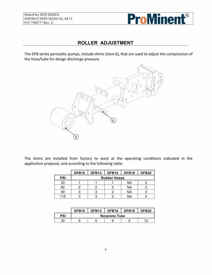
ROLLER ADJUSTMENT The DFB series peristaltic pumps, include shims (item 6), that are used to adjust the compression of the hose/tube for design discharge pressure.
The shims are installed from factory to work at the operating conditions indicated in the application proposal, and according to the following table:
DFB10 DFB13 DFB16 DFB19 DFB22 PSI Rubber Hoses 30 1 1 1 NA 2 60 2 2 2 NA 3 90 3 3 2 NA 3
115 3 3 3 NA 4 DFB10 DFB13 DFB16 DFB19 DFB22
PSI Norprene Tube 30 5 5 9 5 12
6
9

DulcoFlex DFB SERIES INSTRUCTION MANUAL 04.13 P/N 7500777 Rev. C
10
OPERATING CONDITIONS Operating temperatures and pressures are limited by hose/tube construction as follows: MATERIAL TEMPERATURE MIN. (ºF) TEMPERATURE MAX. (ºF) PRESSURE MAX. (PSI)
NR -4 176 115 NBR 14 176 115
EPDM 14 176 115 HYPALON 14 176 115
NORPRENE 275 30

DulcoFlex DFB SERIES INSTRUCTION MANUAL 04.13 P/N 7500777 Rev. C
11
CHECKS BEFORE SWITCHING ON THE PUMP
Check that the pumping equipment has not suffered any damage during transportation or storage, any damage should be notified to the supplier immediately. Check that the supply voltage is suitable for the drive and motor. Hose/Tube: Make sure that the hose/tube is chemically compatible with the fluid to be pumped, that the operating temperature of the fluid does not exceed that recommended and that the operating pressure does not exceed that recommended for the hose/tube. Rollers: If the roller supports are in a resting position, then the pump has come from storage or transportation; change the position to working position. Do not switch on the pump without the pump body cover being correctly installed.
Lubrication. Check that the pump head, the hose/tube and the rollers are liberally lubricated. The specially formulated food grade silicon grease can be obtained from Prominent Fluid Controls or from the local authorized distributor. Check that the thermal protector corresponds with the motor nameplate data.
Check for proper direction of rotation. (rotation test). Check that the optional electrical components are connected to the control panel and test that they function correctly. Check that a proper pressure gauge is installed in the discharge. If the application involves a highly viscous fluid or a long suction pipe, it is recommended that a proper absolute-‐pressure gauge be installed in the suction. If excessive pulsation is anticipated or could be harmful to the system, the installation of a discharge pulsation dampening device is recommended. Check in predicted working conditions that the values of flow, pressure and absorbed power of the motor correspond to the project.

DulcoFlex DFB SERIES INSTRUCTION MANUAL 04.13 P/N 7500777 Rev. C
12
MAINTENANCE Any work carried out on the pump must be done when the pump is stationary and disconnected from the electrical supply.
Lubrication Every hose replacement, Check that the rollers and the hose are properly greased. Add lubricant as necessary to maintain liberal lubrication. The specially formulated food grade silicon grease can be obtained from Prominent Fluid Controls or from the local authorized distributor.
REMOVING OF HOSE -‐ DISASSEMBLY
• Isolate the pump – all suction and discharge valves must be closed to prevent loss of product
and limit personnel exposure. • Disconnect the suction and discharge piping. (flexible connections are suggested) • Remove the front cover. • Remove the roller assembly that is not in contact with the hose/tube. • Replace the cover and rotate the rotor approximately 180° to release the other roller from the
hose/tube. • Separate the press flanges to free the hose/tube, and remove the hose/tube (along with the
inserts if desired).
INSTALLING THE HOSE -‐ ASSEMBLY
• Clean the internal surfaces of the pump body. Lubricate the internal faces of the body of the
pump where there could be friction with the hose. • Inspect the rollers, checking for any damage to the surface and condition of the roller bearings. • Insert the connections in each hose end. • Install the hose in the pump body, and liberally lubricate the hose and the rollers with food
grade silicon grease. • Install the press flanges that fasten the hose and its connections to the pump body. • Replace the roller assembly. • Install the front cover. • Reconnect the suction/discharge piping.
PROBLEMS, CAUSES AND SOLUTIONS

DulcoFlex DFB SERIES INSTRUCTION MANUAL 04.13 P/N 7500777 Rev. C
13
PROBLEM POSSIBLE CAUSE SOLUTIÓN Elevated temperature
Hose with no lubricant Elevated temperature of product Poor or bad suction conditions Rollers not turning properly Excessive pumping speed
Use special lubricant Reduce pumping temperature Clear any obstructions Recalculate sections and lengths Check roller to shaft mounting, bearings Reduce velocity of pump
Reduction of capacity/pressure
Suction or discharge valve closed. Hose insufficiently compressed Rupture of the hose (the product leaks to the casing) Partial obstruction of suction piping Insufficient product amount in suction reservoir Insufficient diameter of suction piping Excessive length of suction pipe High viscosity of product Entry of air via the suction connections High pulsation on suction
Open valves as necessary Check roller/shaft positioning, shimming Replace drive hose Clean piping Fill or stop Increase pipe size/reduce pump speed Shorten suction piping Reduce viscosity Increase suction pipe size Confirm that the pump is suitable Tighten connections and accessories Install pulsation dampener Reconsider application (speed etc.)
Vibrations in pump and piping
The piping is not correctly fitted together Excessive pumping speed Insufficient diameter of piping Baseplate of pump loose Elevated pulsation of pump
Refit piping Reduce the speed of the pump Increase pipe diameter Anchor the baseplate firmly Mount suction or discharge pulsation dampening equipment
Short life of the hose
Chemical attack High speed of pump High pumping temperature High working pressure Abnormal elevation of temperature Unsuitable lubricant Insufficient quantity of grease Cavitation Pump Cavitation of the pump
Confirm compatibility of the hose with the pumped fluid and any cleaning fluids Reduce speed of pump Reduce temperature of product Reduce speed of pump Increase diameter of discharge pipe Check roller shimming Use lubricant from factory Top off lubricant Reconsider suction conditions
Stretching of the hose inside the pump
Insufficient grease High suction pressures (>3 Bar) Hose full of sediment Brackets insufficiently tightened
Top off lubricant Reduce suction pressure Clean hose Retighten brackets
The pump does not start
Insufficient starter power Insufficient power from frequency converter Blockage in the pump
Increase starter power Increase power Check that the voltage is adequate Do not drop below a frequency of 10Hz (confirm this point with the distributor) Start-up will occur at least 10Hz. Check there are no obstructions in the pipe

DulcoFlex DFB SERIES INSTRUCTION MANUAL 04.13 P/N 7500777 Rev. C
14

DulcoFlex DFB SERIES INSTRUCTION MANUAL 04.13 P/N 7500777 Rev. C
15
PARTS LISTING
DFB 10 DFB 13 DFB 16 DFB 19 DFB 22 ITEM Q Part # Part # Part # Part # Part #
1 Pump body 1 7761086 7761086 7761068 7761068 7761321 2 Rotor 1 7761088 7761088 7761069 7761069 7761322 3 Roller shaft 2 7501012 7501012 7501013 7501013 7501014 4 Roller shaft screw 2 NA NA NA NA 7501092 5 Roller 2 7501015 7501015 7501018 7501018 7501020 6 Roller support 2 7501016 7501016 7501017 7501017 7501019 7 Long stud 1 7761074 7761074 7761074 7761074 7761074 8 Short stud 3 7761077 7761077 7761077 7761077 7761077
10 Front cover 0 7501037 7501037 7501038 7501038 7501039 11 Connection SS-NPT 2 7500991 7500996 7500999 7501004 7501007 11 Connection PVC-NPT 2 7500994 7500998 7501003 7501006 7501011 11 Connection PVDF-NPT 2 7500992 7500997 7501000 7501005 7501008 11 Connection TRI_CLAMP 2 7761081 7761103 7761061 7761130 7761332 12 Press flange - Hose 2 7500990 7500995 7501001 NA 7501009 12 Press flange - Tube 2 7500993 7500990 7501002 7501001 7501010 13 Base plate - plastic 1 7747100 7747100 7747100 7747100 7747100 14 Rotor washer 1 7761095 7761095 7761070 7761070 7761337 15 Cover press knob 1 7761084 7761084 7761084 7761084 7761084 16 Cover press knob - blind 3 7761085 7761085 7761085 7761085 7761085 17 Hose in NR,BN,EP,HY,NO 1 Application Specific 18 Gear Reducer / Motor 1 Application Specific 19 Roller ball bearing 4 7501021 7501021 7501022 7501022 7501023 20 Roller lip seal 4 NA NA NA NA 7761339 21 Cover Gasket 1 7761090 7761090 7761073 7761073 7761502 23 Shims 0.5mm 7500987 7500987 7500986 7500986 7500988 23 Shims 5.0mm NA NA NA NA 7500989

DulcoFlex DFB SERIES INSTRUCTION MANUAL 04.13 P/N 7500777 Rev. C
16
WARRANTY
- The contractor shall obtain from the manufacturer its warranty that the equipment shall be warranted for a period of one (1) year from the date of start-up or 18 months from signed delivery acknowledgement, whichever comes first, to be free from defects in materials and workmanship. This warranty does not include the hose or the lubricant as these are elements that have a normal function wear, irrespective of their duration.
- This warranty is valid as long as the equipment functions within the parameters as quoted or on subsequent changes authorized.
- This warranty includes materials and labor only, and does not include
transportation of materials to or from our warehouse in Pittsburgh, PA. Transportation charges will be the responsibility of the customer.