Embed Size (px)
Citation preview
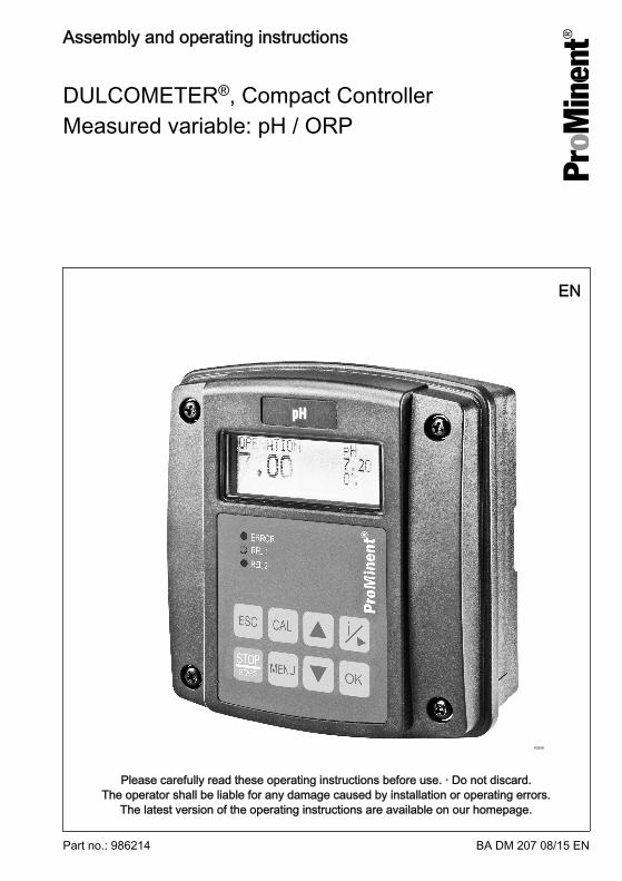
DULCOMETER®, Compact ControllerMeasured variable: pH / ORP
Assembly and operating instructions
A0206
EN
Part no.: 986214 BA DM 207 08/15 EN
Please carefully read these operating instructions before use. · Do not discard.The operator shall be liable for any damage caused by installation or operating errors.
The latest version of the operating instructions are available on our homepage.
General non-discriminatory approach In order to make it easier to read, thisdocument uses the male form in grammat‐ical structures but with an implied neutralsense. It is aimed equally at both men andwomen. We kindly ask female readers fortheir understanding in this simplification ofthe text.
Supplementary information
Please read the supplementary information in its entirety.
Information
This provides important information relating to the correct operation of the unit or isintended to make your work easier.
Safety Information
The safety information includes detailed descriptions of the hazardous situation, seeÄ Chapter 2.1 ‘Explanation of the safety information’ on page 8The following symbols are used to highlight instructions, links, lists, results and other ele‐ments in this document:
More symbols
Symbol Description
Action, step by step
Outcome of an action
Links to elements or sections of these instructions or other applicabledocuments
n List without set order
[Button] Display element (e.g. indicators)
Operating element (e.g. button, switch)
‘Display /GUI’ Screen elements (e.g. buttons, assignment of function keys)
CODE Presentation of software elements and/or texts
Supplemental instructions
2
Table of contents1 Identity code........................................................................................................... 6
2 Introduction............................................................................................................. 82.1 Explanation of the safety information............................................................. 82.2 Users' qualifications...................................................................................... 10
3 Safety and responsibility....................................................................................... 123.1 General Safety Information.......................................................................... 123.2 Correct and proper use................................................................................ 13
4 Functional description........................................................................................... 154.1 Flow diagram................................................................................................ 164.2 Overview of the first level menu................................................................... 17
5 Assembly and installation..................................................................................... 205.1 Scope of delivery.......................................................................................... 225.2 Mounting (mechanical)................................................................................. 225.2.1 Wall mounting............................................................................................ 225.2.2 Pipe mounting........................................................................................... 245.2.3 Control panel mounting............................................................................. 255.3 Installation (electrical)................................................................................... 335.3.1 Cable Cross-Sections and Cable End Sleeves......................................... 345.3.2 Installation of coaxial cable to guard terminal XE1.................................... 345.3.3 Installation (electrical)................................................................................ 395.4 Switching of inductive loads......................................................................... 39
6 Commissioning..................................................................................................... 416.1 Initial commissioning.................................................................................... 416.2 Selection of the measured variable.............................................................. 416.3 Setting the controller during commissioning................................................. 41
7 Operating diagram................................................................................................ 437.1 Overview of equipment/Control elements.................................................... 437.2 Adjusting display contrast............................................................................. 447.3 Continuous display....................................................................................... 457.4 Info display................................................................................................... 457.5 Password...................................................................................................... 47
8 Operating menus for the measured variables pH and ORP................................. 488.1 pH sensor calibration (CAL)......................................................................... 48
Table of contents
3
8.2 Redox sensor calibration (CAL)................................................................... 568.3 Setting limit values [LIMITS]......................................................................... 588.4 Setting the control [CONTROL].................................................................... 608.5 Input setting (INPUT).................................................................................... 638.6 Output setting (OUTPUT)............................................................................. 668.7 DEVICE setting............................................................................................ 70
9 Control parameters and functions......................................................................... 719.1 DULCOMETER® Compact Controller function states ................................. 719.2 STOP/START key........................................................................................ 739.3 Priming (PRIME).......................................................................................... 749.4 Hysteresis limit............................................................................................. 759.5 Temperature correction variable for pH........................................................ 769.6 Checkout time for measured variable and correction variable..................... 779.7 Checkout time control................................................................................... 779.8 Power relay "P-REL" as limit value relay...................................................... 789.9 Setting and functional description of "Relay Used as a Solenoid Valve" .. . . 799.10 Alarm relay................................................................................................. 819.11 "Error logger" operating mode.................................................................... 81
10 Maintenance......................................................................................................... 8210.1 Changing the fuse, DULCOMETER® Compact Controller......................... 8210.2 Fault reporting and troubleshooting............................................................ 83
11 Technical data DULCOMETER® Compact Controller........................................... 8611.1 Permissible ambient conditions.................................................................. 8611.2 Sound Pressure Level................................................................................ 8611.3 Material data............................................................................................... 8711.4 Chemical Resistance.................................................................................. 8711.5 Dimensions and weights............................................................................ 88
12 Electrical data....................................................................................................... 89
13 Spare parts and accessories................................................................................ 92
14 Replacing spare part units ................................................................................... 9314.1 Replacing the top part of the housing......................................................... 9314.2 Replacing the lower part of the housing (wall/tube retaining bracket)........ 9514.3 Replacing the lower part of the housing (control panel installation)........... 97
15 Standards complied with and Declaration of Conformity.................................... 100
Table of contents
4
16 Disposal of Used Parts....................................................................................... 101
17 Index................................................................................................................... 102
Table of contents
5
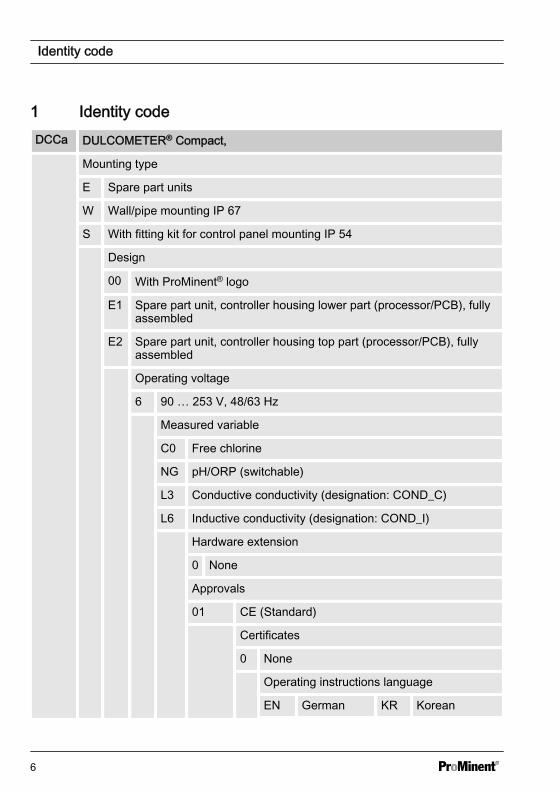
1 Identity codeDCCa DULCOMETER® Compact,
Mounting type
E Spare part units
W Wall/pipe mounting IP 67
S With fitting kit for control panel mounting IP 54
Design
00 With ProMinent® logo
E1 Spare part unit, controller housing lower part (processor/PCB), fullyassembled
E2 Spare part unit, controller housing top part (processor/PCB), fullyassembled
Operating voltage
6 90 … 253 V, 48/63 Hz
Measured variable
C0 Free chlorine
NG pH/ORP (switchable)
L3 Conductive conductivity (designation: COND_C)
L6 Inductive conductivity (designation: COND_I)
Hardware extension
0 None
Approvals
01 CE (Standard)
Certificates
0 None
Operating instructions language
EN German KR Korean
Identity code
6
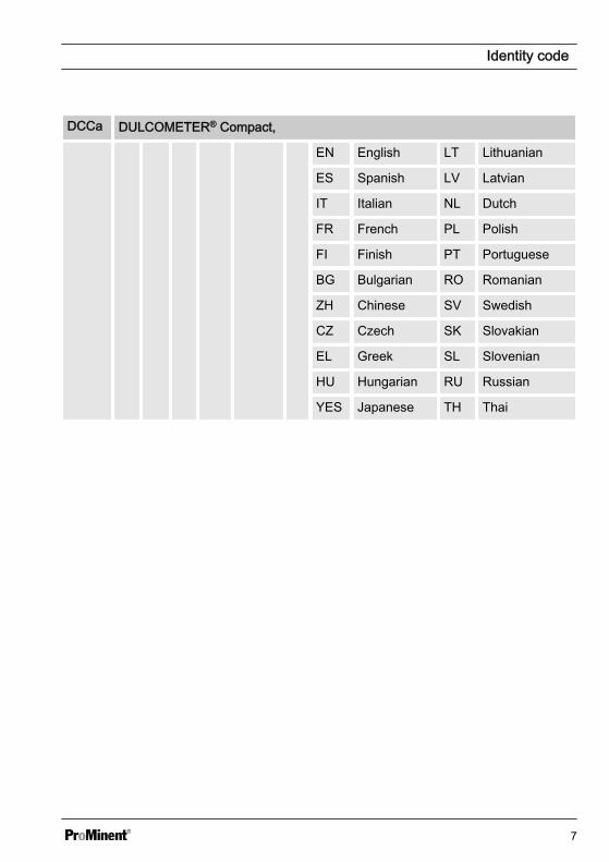
DCCa DULCOMETER® Compact,
EN English LT Lithuanian
ES Spanish LV Latvian
IT Italian NL Dutch
FR French PL Polish
FI Finish PT Portuguese
BG Bulgarian RO Romanian
ZH Chinese SV Swedish
CZ Czech SK Slovakian
EL Greek SL Slovenian
HU Hungarian RU Russian
YES Japanese TH Thai
Identity code
7
2 IntroductionData and functions
These operating instructions describe thetechnical data and functions of theDULCOMETER® Compact Controller,measured variable pH / ORP.
2.1 Explanation of the safetyinformation
Introduction
These operating instructions provide infor‐mation on the technical data and functionsof the product. These operating instruc‐tions provide detailed safety informationand are provided as clear step-by-stepinstructions.
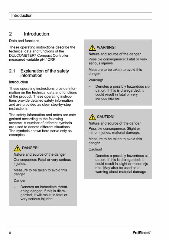
The safety information and notes are cate‐gorised according to the followingscheme. A number of different symbolsare used to denote different situations.The symbols shown here serve only asexamples.
DANGER!
Nature and source of the dangerConsequence: Fatal or very seriousinjuries.
Measure to be taken to avoid thisdanger
Danger!
– Denotes an immediate threat‐ening danger. If this is disre‐garded, it will result in fatal orvery serious injuries.
WARNING!
Nature and source of the dangerPossible consequence: Fatal or veryserious injuries.
Measure to be taken to avoid thisdanger
Warning!
– Denotes a possibly hazardous sit‐uation. If this is disregarded, itcould result in fatal or veryserious injuries.
CAUTION!
Nature and source of the dangerPossible consequence: Slight orminor injuries, material damage.
Measure to be taken to avoid thisdanger
Caution!
– Denotes a possibly hazardous sit‐uation. If this is disregarded, itcould result in slight or minor inju‐ries. May also be used as awarning about material damage.
Introduction
8
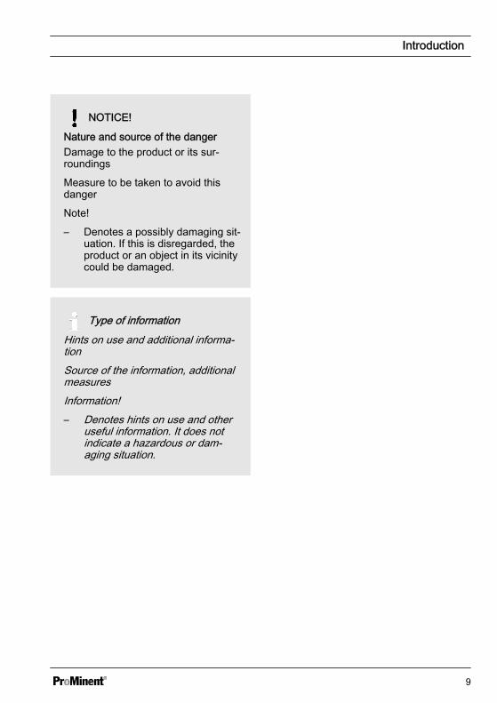
NOTICE!
Nature and source of the dangerDamage to the product or its sur‐roundings
Measure to be taken to avoid thisdanger
Note!
– Denotes a possibly damaging sit‐uation. If this is disregarded, theproduct or an object in its vicinitycould be damaged.
Type of informationHints on use and additional informa‐tionSource of the information, additionalmeasuresInformation!– Denotes hints on use and other
useful information. It does notindicate a hazardous or dam‐aging situation.
Introduction
9
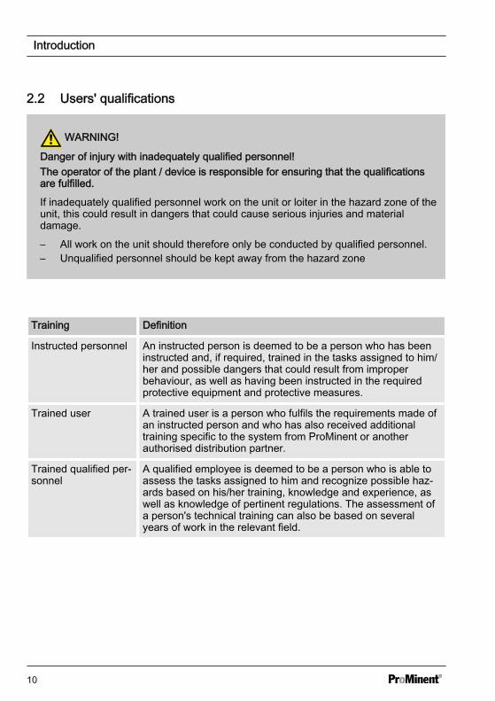
2.2 Users' qualifications
WARNING!
Danger of injury with inadequately qualified personnel!The operator of the plant / device is responsible for ensuring that the qualificationsare fulfilled.
If inadequately qualified personnel work on the unit or loiter in the hazard zone of theunit, this could result in dangers that could cause serious injuries and materialdamage.
– All work on the unit should therefore only be conducted by qualified personnel.– Unqualified personnel should be kept away from the hazard zone
Training Definition
Instructed personnel An instructed person is deemed to be a person who has beeninstructed and, if required, trained in the tasks assigned to him/her and possible dangers that could result from improperbehaviour, as well as having been instructed in the requiredprotective equipment and protective measures.
Trained user A trained user is a person who fulfils the requirements made ofan instructed person and who has also received additionaltraining specific to the system from ProMinent or anotherauthorised distribution partner.
Trained qualified per‐sonnel
A qualified employee is deemed to be a person who is able toassess the tasks assigned to him and recognize possible haz‐ards based on his/her training, knowledge and experience, aswell as knowledge of pertinent regulations. The assessment ofa person's technical training can also be based on severalyears of work in the relevant field.
Introduction
10
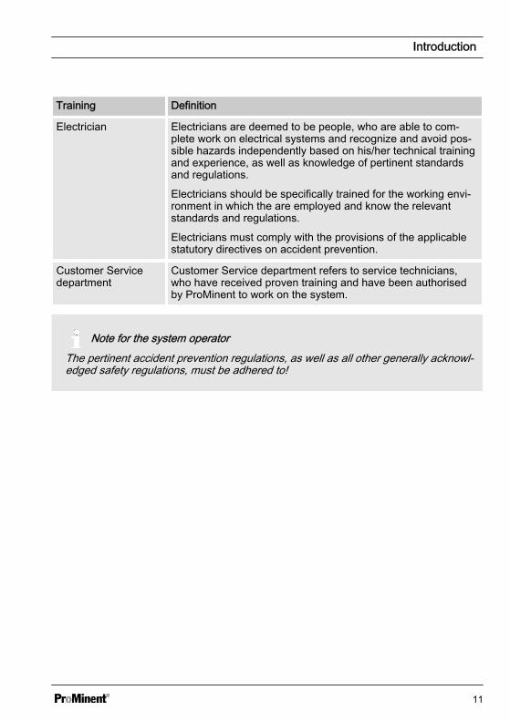
Training Definition
Electrician Electricians are deemed to be people, who are able to com‐plete work on electrical systems and recognize and avoid pos‐sible hazards independently based on his/her technical trainingand experience, as well as knowledge of pertinent standardsand regulations.
Electricians should be specifically trained for the working envi‐ronment in which the are employed and know the relevantstandards and regulations.
Electricians must comply with the provisions of the applicablestatutory directives on accident prevention.
Customer Servicedepartment
Customer Service department refers to service technicians,who have received proven training and have been authorisedby ProMinent to work on the system.
Note for the system operatorThe pertinent accident prevention regulations, as well as all other generally acknowl‐edged safety regulations, must be adhered to!
Introduction
11
3 Safety and responsibility3.1 General Safety Information
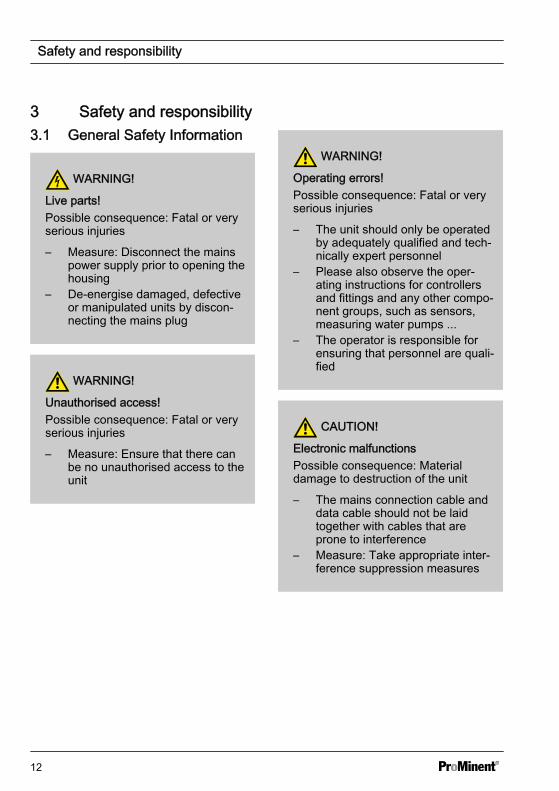
WARNING!
Live parts!Possible consequence: Fatal or veryserious injuries
– Measure: Disconnect the mainspower supply prior to opening thehousing
– De-energise damaged, defectiveor manipulated units by discon‐necting the mains plug
WARNING!
Unauthorised access!Possible consequence: Fatal or veryserious injuries
– Measure: Ensure that there canbe no unauthorised access to theunit
WARNING!
Operating errors!Possible consequence: Fatal or veryserious injuries
– The unit should only be operatedby adequately qualified and tech‐nically expert personnel
– Please also observe the oper‐ating instructions for controllersand fittings and any other compo‐nent groups, such as sensors,measuring water pumps ...
– The operator is responsible forensuring that personnel are quali‐fied
CAUTION!
Electronic malfunctionsPossible consequence: Materialdamage to destruction of the unit
– The mains connection cable anddata cable should not be laidtogether with cables that areprone to interference
– Measure: Take appropriate inter‐ference suppression measures
Safety and responsibility
12

NOTICE!
Correct and proper useDamage to the product or its sur‐roundings
– The unit is not intended tomeasure or regulate gaseous orsolid media
– The unit may only be used inaccordance with the technicaldetails and specifications pro‐vided in these operating instruc‐tions and in the operating instruc‐tions for the individualcomponents
NOTICE!
Correct sensor operation / Run-intimeDamage to the product or its sur‐roundings
– Correct measuring and dosing isonly possible if the sensor isworking perfectly
– It is imperative that the run-intimes of the sensors are adheredto
– The run-in times should beallowed for when planning initialoperation
– It may take a whole working dayto run-in the sensor
– Please read the operating instruc‐tions for the sensor
NOTICE!
Correct sensor operationDamage to the product or its sur‐roundings
– Correct measuring and dosing isonly possible if the sensor isworking perfectly
– Check and calibrate the sensorregularly
NOTICE!
Compensation of control deviationsDamage to the product or its sur‐roundings
– This controller cannot be used incontrol circuits which requirerapid compensation (< 30 s)
3.2 Correct and proper use
NOTICE!
Compensation for control deviationsDamage to the product or its sur‐roundings
– The controller can be used in pro‐cesses, which require compensa‐tion of > 30 seconds
Safety and responsibility
13
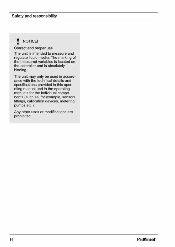
NOTICE!
Correct and proper useThe unit is intended to measure andregulate liquid media. The marking ofthe measured variables is located onthe controller and is absolutelybinding.
The unit may only be used in accord‐ance with the technical details andspecifications provided in this oper‐ating manual and in the operatingmanuals for the individual compo‐nents (such as, for example, sensors,fittings, calibration devices, meteringpumps etc.).
Any other uses or modifications areprohibited.
Safety and responsibility
14
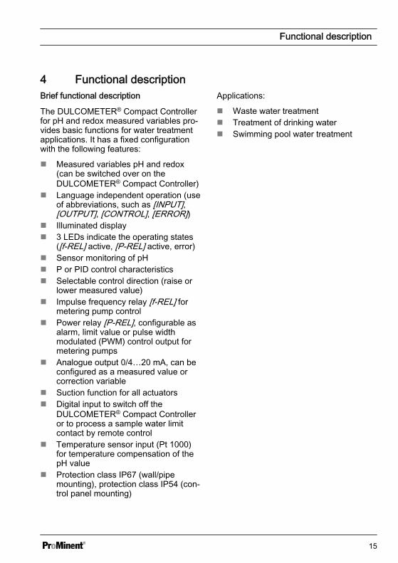
4 Functional descriptionBrief functional description
The DULCOMETER® Compact Controllerfor pH and redox measured variables pro‐vides basic functions for water treatmentapplications. It has a fixed configurationwith the following features:
n Measured variables pH and redox(can be switched over on theDULCOMETER® Compact Controller)
n Language independent operation (useof abbreviations, such as [INPUT],[OUTPUT], [CONTROL], [ERROR])
n Illuminated displayn 3 LEDs indicate the operating states
([f-REL] active, [P-REL] active, error)n Sensor monitoring of pHn P or PID control characteristicsn Selectable control direction (raise or
lower measured value)n Impulse frequency relay [f-REL] for
metering pump controln Power relay [P-REL], configurable as
alarm, limit value or pulse widthmodulated (PWM) control output formetering pumps
n Analogue output 0/4…20 mA, can beconfigured as a measured value orcorrection variable
n Suction function for all actuatorsn Digital input to switch off the
DULCOMETER® Compact Controlleror to process a sample water limitcontact by remote control
n Temperature sensor input (Pt 1000)for temperature compensation of thepH value
n Protection class IP67 (wall/pipemounting), protection class IP54 (con‐trol panel mounting)
Applications:
n Waste water treatmentn Treatment of drinking watern Swimming pool water treatment
Functional description
15
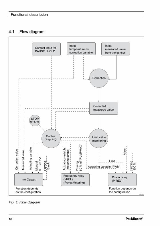
4.1 Flow diagram
mA OutputFrequency relay (f-REL) (Pump:Metering)
Power relay (P-REL)
Corrected measured value
Input temperature as correction variable
Contact input for PAUSE / HOLD
Input measured value from the sensor
Control (P or PID)
Correction
Alar
m
Limit
Actuating variable (PWM)
Actu
atin
g va
riabl
e
Mea
sure
d va
lue
Cor
rect
ion
valu
e
Actu
atin
g va
riabl
e (m
eter
ing
stro
ke)
Function depends on the configuration
Limit value monitoring
A0325
STOP START
Man
ual
0 ...
25
mA
Function depends on the configuration
Prim
ing
16 m
A
Prim
ing
80
% o
f "PU
MPM
AX"
Prim
ing
100
%
Fig. 1: Flow diagram
Functional description
16
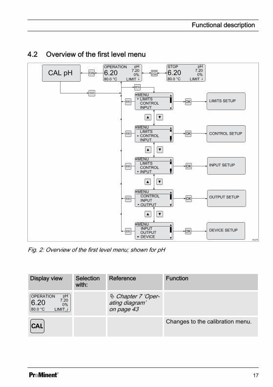
4.2 Overview of the first level menu
A0276
OPERATION pH
6.2080.0 °C
7.200%
LIMIT ↓
≡MENU
MENU
LIMITSCONTROLINPUT
LIMITS SETUP
≡MENULIMITSCONTROLINPUT
≡MENULIMITSCONTROLINPUT
≡MENU
OUTPUT
CONTROLINPUT
≡MENU
DEVICEOUTPUTINPUT
ESC
ESC
ESC
ESC
ESC
CONTROL SETUP
INPUT SETUP
OUTPUT SETUP
DEVICE SETUP
STOP pH
6.2080.0 °C
7.200%
LIMIT ↓STARTSTOPCAL pH CAL
ESC
Fig. 2: Overview of the first level menu; shown for pH
Display view Selectionwith:
Reference Function
OPERATION pH
6.2080.0 °C
7.200%
LIMIT ↓A0329
Ä Chapter 7 ‘Oper‐ating diagram’on page 43
Changes to the calibration menu.
Functional description
17
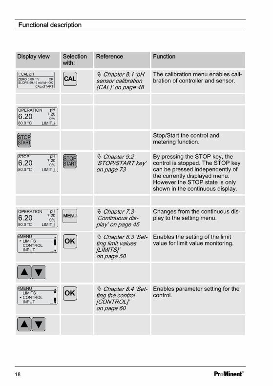
Display view Selectionwith:
Reference Function
CAL pH
SLOPE 59.16 mV/pH OKCAL=START
ZERO 0.00 mV OK
A0332
Ä Chapter 8.1 ‘pHsensor calibration(CAL)’ on page 48
The calibration menu enables cali‐bration of controller and sensor.
OPERATION pH
6.2080.0 °C
7.200%
LIMIT ↓A0329
Stop/Start the control andmetering function.
STOP pH
6.2080.0 °C
7.200%
LIMIT ↓A0333
Ä Chapter 9.2‘STOP/START key’on page 73
By pressing the STOP key, thecontrol is stopped. The STOP keycan be pressed independently ofthe currently displayed menu.However the STOP state is onlyshown in the continuous display.
OPERATION pH
6.2080.0 °C
7.200%
LIMIT ↓A0329
Ä Chapter 7.3‘Continuous dis‐play’ on page 45
Changes from the continuous dis‐play to the setting menu.
≡MENULIMITSCONTROLINPUT A0326
Ä Chapter 8.3 ‘Set‐ting limit values[LIMITS]’on page 58
Enables the setting of the limitvalue for limit value monitoring.
≡MENULIMITSCONTROLINPUT A0327
Ä Chapter 8.4 ‘Set‐ting the control[CONTROL]’on page 60
Enables parameter setting for thecontrol.
Functional description
18

Display view Selectionwith:
Reference Function
≡MENULIMITSCONTROLINPUT A0328
Ä Chapter 8.5‘Input setting(INPUT)’on page 63
Enables setting of the measuredvalue input parameter.
≡MENU
OUTPUT
CONTROLINPUT
A0330
Ä Chapter 8.6 ‘Output setting(OUTPUT)’on page 66
Enables setting of the mA outputparameter.
≡MENU
DEVICEOUTPUTINPUT
A0331
Ä Chapter 8.7‘DEVICE setting’on page 70
Enables adjustment of the pass‐word and the controller[RESTART] function.
Functional description
19
5 Assembly and installationn User qualification, mechanical instal‐
lation: trained qualified personnel, seeÄ Chapter 2.2 ‘Users' qualifications’on page 10
n User qualification, electrical installa‐tion: Electrical technician, seeÄ Chapter 2.2 ‘Users' qualifications’on page 10
CAUTION!
Possible consequence: Materialdamage.
The hinge between the front and rearpart of the housing cannot absorbhigh levels of mechanical loading.When working on theDULCOMETER® Compact Controller,firmly hold the top section of the con‐troller housing.
CAUTION!
Check band for strain reliefPossible consequence: Materialdamage.
The ribbon cable and its socketcannot be mechanically loaded.Hence it is essential that whenmounting the controller in the controlpanel mounting, the check strap (partnumber 1035918) is fitted for strainrelief and mechanical securing.Without the check strap, the ribboncable or its socket could be damagedif they were to fall out of the controllerupper housing.
NOTICE!
Mounting position and conditions– The controller conforms to IP 67
degree of protection (wall/pipemounting) or IP 54 (control panelmounting) requirements. Thisdegree of protection is only ach‐ieved if all seals and cable glandsare correctly fitted.
– The (electrical) installation shouldonly take place after (mechanical)installation
– Ensure that there is unimpededaccess for operation
– Ensure safe and low-vibrationfastening
– Avoid direct sunlight– Permissible ambient temperature
of the controller at the installationlocation: -10 ... +60 °C at max.95% relative air humidity (non-condensing)
– Take into consideration the per‐missible ambient temperature ofthe sensors and other compo‐nents connected
– The controller is only suitable foroperation in closed rooms. Ifoperated outside, the controllermust be protected against theenvironment by a suitable protec‐tive enclosure
Read-off and operating position– Install the device in a favourable
position for reading and operating(preferably at eye level)
Assembly and installation
20
Mounting position– Leave sufficient free space for the
cables
Packaging materialDispose of packaging material in anenvironmentally responsible way. Allpackaging components carry the cor‐responding recycling code .
Assembly and installation
21
5.1 Scope of deliveryThe following parts belong to the standard scope of delivery of a DULCOMETER® Com‐pact Controller.
Description Quantity
Assembled device 1
Cable connection set DMTa/DXMa (metr.) 1
Operating instructions 1
5.2 Mounting (mechanical)The DULCOMETER® Compact Controller is suitable for mounting on a wall, pipe or con‐trol panel.
Mounting materials (contained in the scope of supply):
Description Quantity
Wall/tube retaining bracket 1
Round head screws 5x45 mm 2
Washer 5.3 2
Rawlplug Ø 8 mm, plastic 2
5.2.1 Wall mountingMounting (mechanical)
Assembly and installation
22

2
1
A0273
Fig. 3: Removing the wall/pipe bracket1. Remove the wall/pipe bracket. Pull
the two snap-hooks (1) outwardsand push upwards
2. Fold out the wall/pipe bracket (2)and pull out in a downwards direc‐tion
3. Mark two drill holes diagonal toeach other by using the wall/pipebracket as a drilling template
4. Drill holes: Ø 8 mm, d = 50 mm
A0274
Fig. 4: Screwing on the wall/pipe bracketusing washers5. Screw on the wall/pipe bracket
using the washers
6. Suspend the DULCOMETER®
Compact Controller at the top in thewall/pipe bracket and push usinglight pressure at the bottom againstthe wall/pipe bracket. Then pressupwards until the DULCOMETER®
Compact Controller audibly snapsinto position.
Assembly and installation
23
5.2.2 Pipe mountingMounting (mechanical)
Pipe diameterPipe diameter: 25 mm to 60 mm.
2
1
A0273
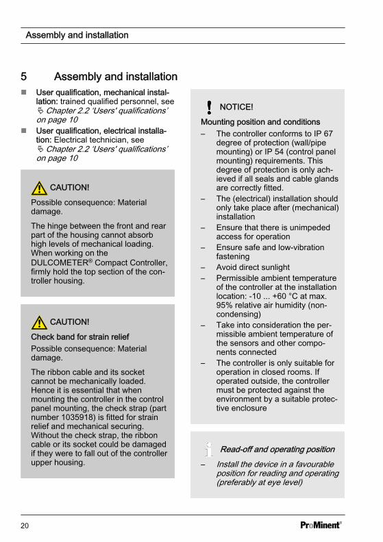
Fig. 5: Removing the wall/pipe bracket1. Remove the wall/pipe bracket. Pull
the two snap-hooks (1) outwardsand push upwards
2. Fold out the wall/pipe bracket (2)and pull out in a downwards direc‐tion
3. Secure the wall/pipe bracket usingcable ties (or pipe clips) to the pipe
A0275
3
2
1
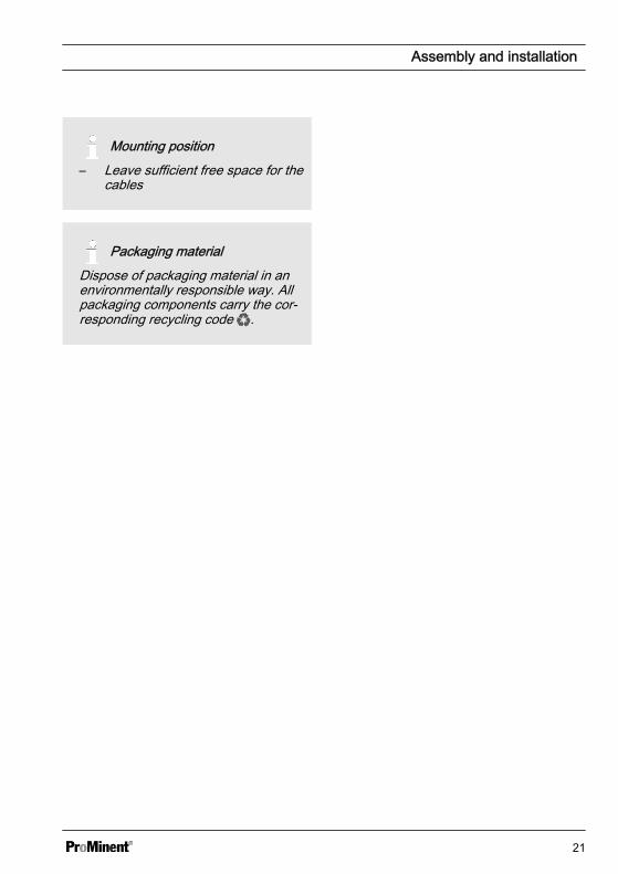
Fig. 6: Suspend and secure theDULCOMETER® Compact Controller4. Suspend the DULCOMETER®
Compact Controller at the top (1) inthe wall/pipe bracket and pushusing light pressure at the bottom(2) against the wall/pipe bracket.Then press upwards (3) until theDULCOMETER® Compact Con‐troller audibly snaps into position
Assembly and installation
24
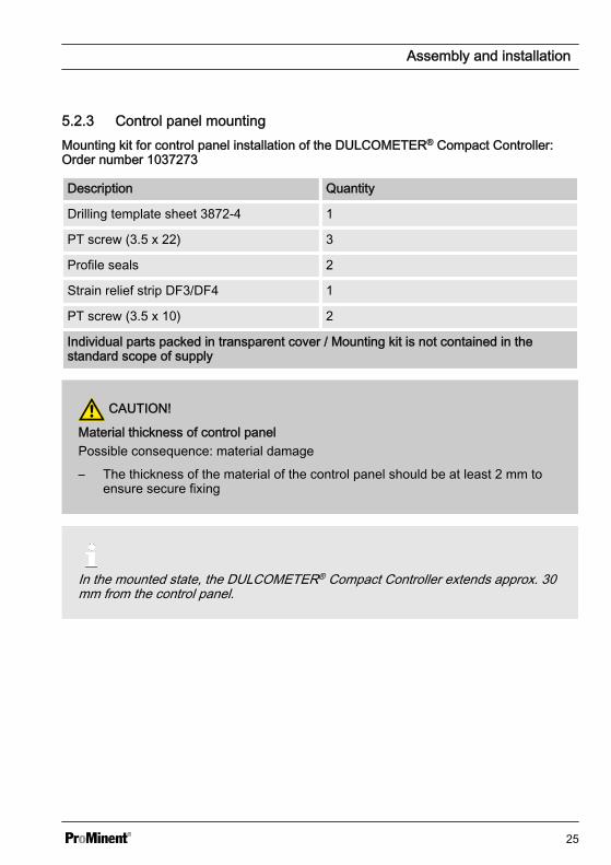
5.2.3 Control panel mountingMounting kit for control panel installation of the DULCOMETER® Compact Controller:Order number 1037273
Description Quantity
Drilling template sheet 3872-4 1
PT screw (3.5 x 22) 3
Profile seals 2
Strain relief strip DF3/DF4 1
PT screw (3.5 x 10) 2
Individual parts packed in transparent cover / Mounting kit is not contained in thestandard scope of supply
CAUTION!
Material thickness of control panelPossible consequence: material damage
– The thickness of the material of the control panel should be at least 2 mm toensure secure fixing
In the mounted state, the DULCOMETER® Compact Controller extends approx. 30mm from the control panel.
Assembly and installation
25
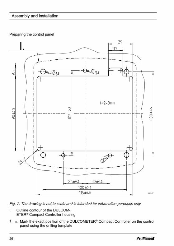
Preparing the control panel
I.
A0347
Fig. 7: The drawing is not to scale and is intended for information purposes only.I. Outline contour of the DULCOM‐
ETER® Compact Controller housing
1. Mark the exact position of the DULCOMETER® Compact Controller on the controlpanel using the drilling template
Assembly and installation
26
2.
Core holeAdhere to the 3.5 mm Ø as the core hole diameter for screwing in the fixingbolts.
Drill four holes for the bolts for the top section of the controller housing using a 3.5mm Ø drill bit
3. Drill three holes for the bolts for the bottom section of the controller housing usinga 4.5 mm Ø drill bit
4. Drill four holes using an 8 mm Ø drill bit and use a jigsaw to cut the cut-out
ð Deburr all the edges.
Assembly and installation
27
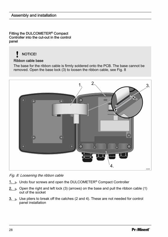
Fitting the DULCOMETER® CompactController into the cut-out in the controlpanel
NOTICE!
Ribbon cable baseThe base for the ribbon cable is firmly soldered onto the PCB. The base cannot beremoved. Open the base lock (3) to loosen the ribbon cable, see Fig. 8
1. 2. 3.
4.
Fig. 8: Loosening the ribbon cable1. Undo four screws and open the DULCOMETER® Compact Controller
2. Open the right and left lock (3) (arrows) on the base and pull the ribbon cable (1)out of the socket
3. Use pliers to break off the catches (2 and 4). These are not needed for controlpanel installation
Assembly and installation
28
1.2.
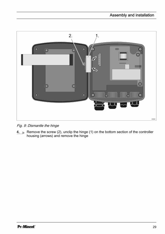
Fig. 9: Dismantle the hinge4. Remove the screw (2), unclip the hinge (1) on the bottom section of the controller
housing (arrows) and remove the hinge
Assembly and installation
29
A03601.
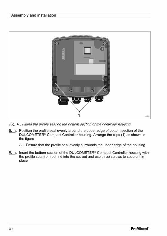
Fig. 10: Fitting the profile seal on the bottom section of the controller housing5. Position the profile seal evenly around the upper edge of bottom section of the
DULCOMETER® Compact Controller housing. Arrange the clips (1) as shown inthe figure
ð Ensure that the profile seal evenly surrounds the upper edge of the housing.
6. Insert the bottom section of the DULCOMETER® Compact Controller housing withthe profile seal from behind into the cut-out and use three screws to secure it inplace
Assembly and installation
30
A0351
1.
2.1.
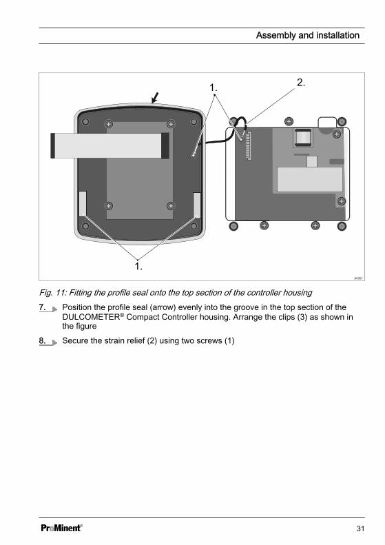
Fig. 11: Fitting the profile seal onto the top section of the controller housing7. Position the profile seal (arrow) evenly into the groove in the top section of the
DULCOMETER® Compact Controller housing. Arrange the clips (3) as shown inthe figure
8. Secure the strain relief (2) using two screws (1)
Assembly and installation
31
A0352
1.
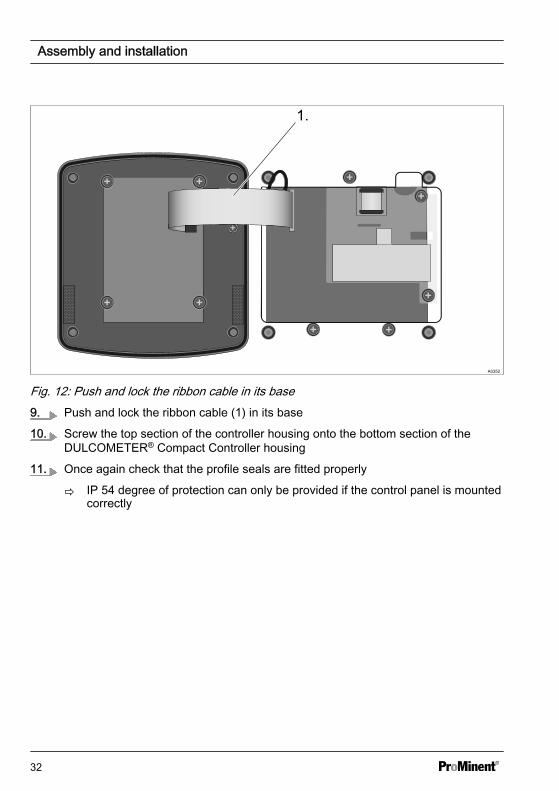
Fig. 12: Push and lock the ribbon cable in its base9. Push and lock the ribbon cable (1) in its base
10. Screw the top section of the controller housing onto the bottom section of theDULCOMETER® Compact Controller housing
11. Once again check that the profile seals are fitted properly
ð IP 54 degree of protection can only be provided if the control panel is mountedcorrectly
Assembly and installation
32
5.3 Installation (electrical)
WARNING!
Live parts!Possible consequence: Fatal or veryserious injuries
– Measure: Disconnect the elec‐trical power supply to the devicebefore opening the housing andsecure to prevent unintentionalreconnection
– Disconnect damaged or defectivedevices or devices that havebeen tampered with and preventunintended reconnection
– The provision of a suitable iso‐lating device (emergency-offswitch, etc.) is the responsibilityof the plant operator
The signal leads of theDULCOMETER® Compact Controllermust not be routed alongside interfer‐ence-prone cabling. Faults could leadto malfunctions of theDULCOMETER® Compact Controller.
Assembly and installation
33
5.3.1 Cable Cross-Sections and Cable End Sleeves
Minimum cross-sec‐tion
Maximum cross-section
Stripped insulationlength
Without cable endsleeve
0.25 mm2 1.5 mm2
Cable end sleevewithout insulation
0.20 mm2 1.0 mm2 8 - 9 mm
Cable end sleevewith insulation
0.20 mm2 1.0 mm2 10 - 11 mm
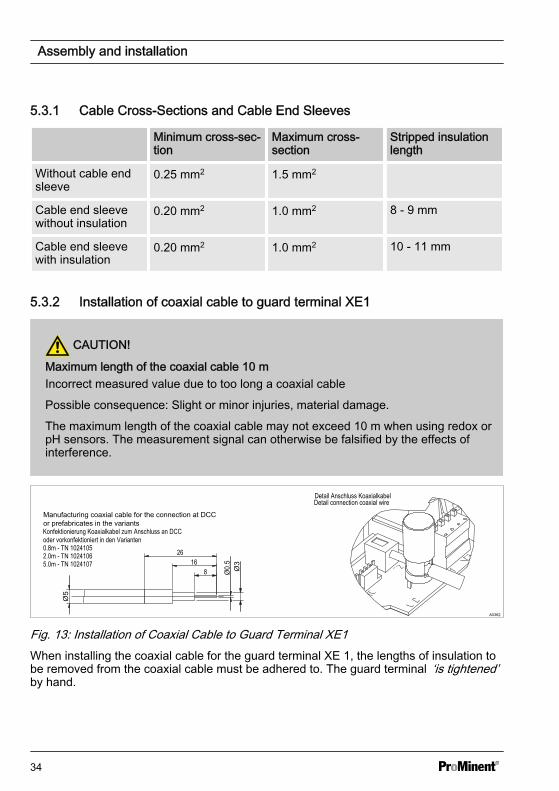
5.3.2 Installation of coaxial cable to guard terminal XE1
CAUTION!
Maximum length of the coaxial cable 10 mIncorrect measured value due to too long a coaxial cable
Possible consequence: Slight or minor injuries, material damage.
The maximum length of the coaxial cable may not exceed 10 m when using redox orpH sensors. The measurement signal can otherwise be falsified by the effects ofinterference.
Konfektionierung Koaxialkabel zum Anschluss an DCCoder vorkonfektioniert in den Varianten
Detail Anschluss Koaxialkabel
A0362
Fig. 13: Installation of Coaxial Cable to Guard Terminal XE1When installing the coaxial cable for the guard terminal XE 1, the lengths of insulation tobe removed from the coaxial cable must be adhered to. The guard terminal ‘is tightened’by hand.
Assembly and installation
34
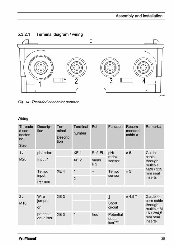
5.3.2.1 Terminal diagram / wiring
A0348
Fig. 14: Threaded connector number
Wiring
Threaded con‐nectorno.
Size
Descrip‐tion
Ter‐minal
Description
Terminal
number
Pol Function Recom‐mendedcable
Remarks
1 /
M20
ph/redox
Input 1
XE 1 Ref. El. pH/redoxsensor
5 GuidecablethroughmultipleM20 / 2x5mm sealinserts
XE 2 meas.sig
Temp.input
Pt 1000
XE 4 1 + Temp.sensor
5
2 -
2 /
M16
Wirejumper
or
potentialequaliser
XE 3
Shortcircuit
4,5 * Guide 4-core cablethroughmultiple M16 / 2x4,5mm sealinserts
XE 3 1 free Potentialequal‐iser***
Assembly and installation
35
Threaded con‐nectorno.
Size
Descrip‐tion
Ter‐minal
Description
Terminal
number
Pol Function Recom‐mendedcable
Remarks
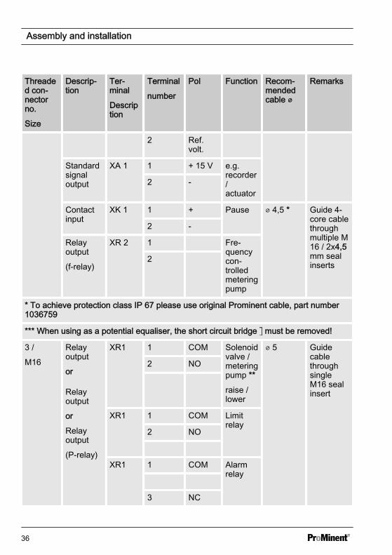
2 Ref.volt.
Standardsignaloutput
XA 1 1 + 15 V e.g.recorder/actuator
2 -
Contactinput
XK 1 1 + Pause 4,5 * Guide 4-core cablethroughmultiple M16 / 2x4,5mm sealinserts
2 -
Relayoutput
(f-relay)
XR 2 1 Fre‐quencycon‐trolledmeteringpump
2
* To achieve protection class IP 67 please use original Prominent cable, part number1036759
*** When using as a potential equaliser, the short circuit bridge must be removed!
3 /
M16
Relayoutput
or
Relayoutput
or
Relayoutput
(P-relay)
XR1 1 COM Solenoidvalve /meteringpump **
raise /lower
5 GuidecablethroughsingleM16 sealinsert
2 NO
XR1 1 COM Limitrelay
2 NO
XR1 1 COM Alarmrelay
3 NC
Assembly and installation
36
Threaded con‐nectorno.
Size
Descrip‐tion
Ter‐minal
Description
Terminal
number
Pol Function Recom‐mendedcable
Remarks
** An RC suppressor must be connected (not part of the scope of delivery)
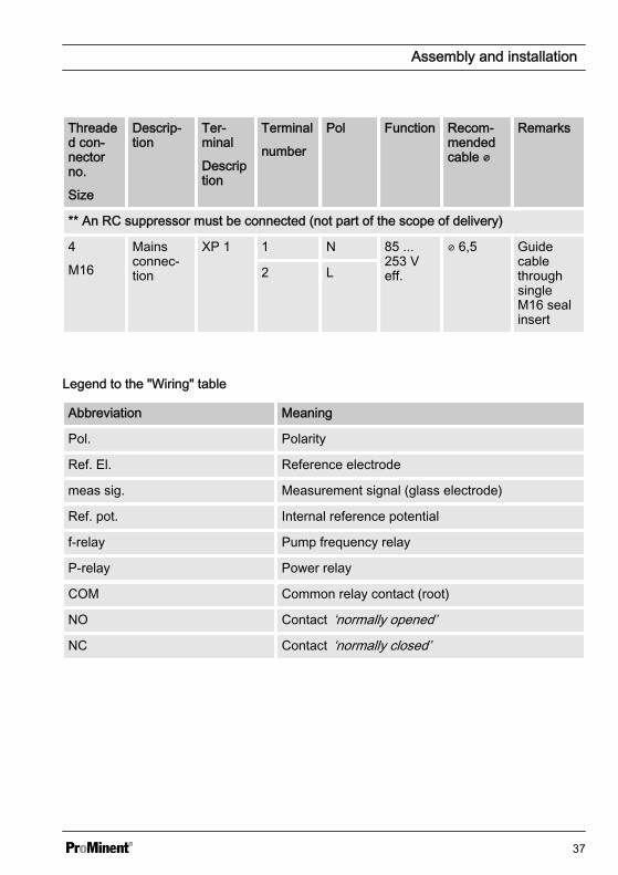
4
M16
Mainsconnec‐tion
XP 1 1 N 85 ...253 Veff.
6,5 GuidecablethroughsingleM16 sealinsert
2 L
Legend to the "Wiring" table
Abbreviation Meaning
Pol. Polarity
Ref. El. Reference electrode
meas sig. Measurement signal (glass electrode)
Ref. pot. Internal reference potential
f-relay Pump frequency relay
P-relay Power relay
COM Common relay contact (root)
NO Contact ‘normally opened’
NC Contact ‘normally closed’
Assembly and installation
37
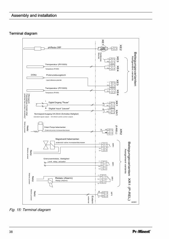
Terminal diagram
Ne
tz
pH/Redox ORP
Temperatur (Pt1000)
Digital Eingang "Pause"
Offen/geschl.
Potenzialfreier Kontakt nötig!
Drahtbrücke
+-
Extern Pumpe heben/senken
Normsignal-Ausgang 0/4-20mA (Schreiber,Stellglied)
2
Temperatur (Pt1000)
Potenzialausgleich
Assig
nm
en
t varia
nts
Bele
gungsva
riante
n
Ne
tzMagnetventil heben/senken
Ne
tzN
etz
Relais (Alarm)
Grenzwertrelais, Stellglied
Exte
rn
Bele
gungsva
riante
n X
R1 (P
-RE
L)
A0361
Fig. 15: Terminal diagram
Assembly and installation
38
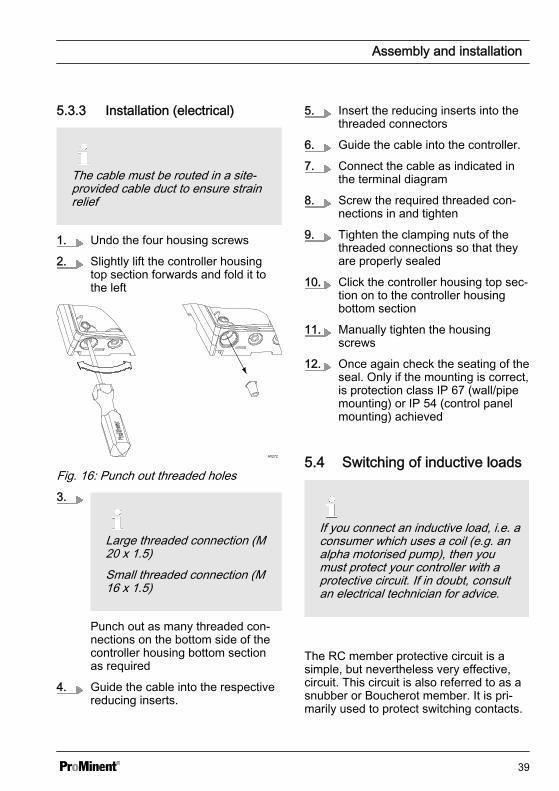
5.3.3 Installation (electrical)
The cable must be routed in a site-provided cable duct to ensure strainrelief
1. Undo the four housing screws
2. Slightly lift the controller housingtop section forwards and fold it tothe left
A0272
Fig. 16: Punch out threaded holes3.
Large threaded connection (M20 x 1.5)Small threaded connection (M16 x 1.5)
Punch out as many threaded con‐nections on the bottom side of thecontroller housing bottom sectionas required
4. Guide the cable into the respectivereducing inserts.
5. Insert the reducing inserts into thethreaded connectors
6. Guide the cable into the controller.
7. Connect the cable as indicated inthe terminal diagram
8. Screw the required threaded con‐nections in and tighten
9. Tighten the clamping nuts of thethreaded connections so that theyare properly sealed
10. Click the controller housing top sec‐tion on to the controller housingbottom section
11. Manually tighten the housingscrews
12. Once again check the seating of theseal. Only if the mounting is correct,is protection class IP 67 (wall/pipemounting) or IP 54 (control panelmounting) achieved
5.4 Switching of inductive loads
If you connect an inductive load, i.e. aconsumer which uses a coil (e.g. analpha motorised pump), then youmust protect your controller with aprotective circuit. If in doubt, consultan electrical technician for advice.
The RC member protective circuit is asimple, but nevertheless very effective,circuit. This circuit is also referred to as asnubber or Boucherot member. It is pri‐marily used to protect switching contacts.
Assembly and installation
39
When switching off, the connection inseries of a resistor and capacitor meansthat the current can be dissipated in adamped oscillation.
Also when switching on, the resistor actsas a current limiter for the capacitorcharging process. The RC member pro‐tective circuit is highly suitable for ACvoltage supplies.
The magnitude of the resistance R ofthe RC member is determined accordingto the following equation:
R=U/IL(Where U= Voltage across the load andIL = current through the load)
The magnitude of the capacitor is deter‐mined using the following equation:
C=k * ILk=0,1...2 (dependent on the application).
Only use capacitors of class X2.
Units: R = Ohm; U = Volt; IL = Ampere;C = µF
If consumers are connected whichhave a high starting current (e.g. plug-in, switched mains power supplies),then a means of limiting the startingcurrent must be provided.
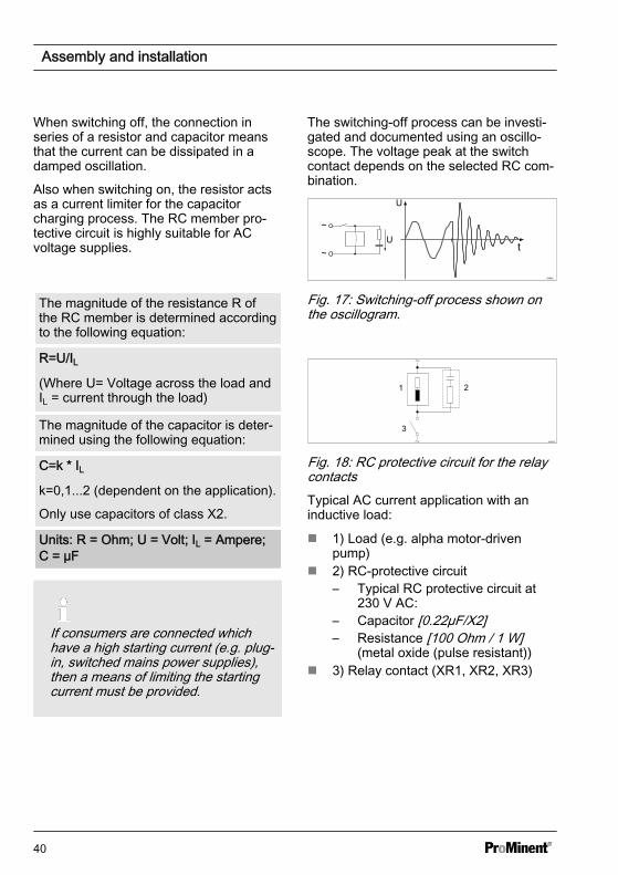
The switching-off process can be investi‐gated and documented using an oscillo‐scope. The voltage peak at the switchcontact depends on the selected RC com‐bination.
A0842
Fig. 17: Switching-off process shown onthe oscillogram.
A0835
Fig. 18: RC protective circuit for the relaycontactsTypical AC current application with aninductive load:
n 1) Load (e.g. alpha motor-drivenpump)
n 2) RC-protective circuit– Typical RC protective circuit at
230 V AC:– Capacitor [0.22µF/X2]– Resistance [100 Ohm / 1 W]
(metal oxide (pulse resistant))n 3) Relay contact (XR1, XR2, XR3)
Assembly and installation
40
6 Commissioningn Users' qualification: trained user, see
Ä Chapter 2.2 ‘Users' qualifications’on page 10
WARNING!
Sensor run-in periodsThis can result in hazardous incorrectmetering
– Correct measuring and meteringis only possible if the sensor isworking perfectly
– Please read the operating manualfor the sensor
– The sensor must be calibratedafter commissioning
Following completion of mechanical andelectrical assembly, the DULCOMETER®
Compact Controller should be integratedinto the measuring point.
6.1 Initial commissioningWhen first switching on theDULCOMETER® Compact Controller theDULCOMETER® Compact Controller is ina STOP state.
Selection of the measurement variable,controller setting and setting of the var‐ious, process-dependent, parameterstakes place next. Ä Chapter 8 ‘Operatingmenus for the measured variables pH andORP’ on page 48.
6.2 Selection of the measuredvariable
The pH and redox measurement variablesare set in the ‘INPUT’ menu.
NOTICE!
Reset to factory settingsIf you set or switch the measurementvariable, all parameters in the con‐troller are reset to the factory settingsfor the selected measurement vari‐able.
You must then reset all the controllerfunctions.
6.3 Setting the controller duringcommissioning
NOTICE!
Reset to factory settingsWhen switching over the meteringdirection, all actuators in theDULCOMETER® Compact Controllerare reset to the factory settings for theselected metering direction.
For safety reasons, all actuators aredeactivated. The base load is reset to0 %. All parameters relating to theactuator, are reset to the factory set‐ting.
Consequently all parameters relatingto the actuator, must be reset.
Commissioning
41
The DULCOMETER® Compact Controlleronly controls ‘one-way’ . Only one positionor one negative control variable can becalculated. The direction of the controlvariable is set in the ‘PUMP’ menu. Thereis no dead zone. In this sense, controlcannot be ‘switched off’ (except with‘STOP’ or ‘PAUSE’ ).The value of the P-proportion of the con‐trol (Xp) is specified with theDULCOMETER® Compact Controller inthe units of the corresponding measure‐ment variable (e.g. 1.5 pH).
For pure P-control and a separationbetween the set and actual values, whichcorresponds to the Xp value, the calcu‐lated control variable is +100 % (with thesetting ‘raise’ ) or -100 % (with the setting‘lower’ ).
Commissioning
42
7 Operating diagram7.1 Overview of equipment/Control elementsn User qualification: instructed user, see Ä Chapter 2.2 ‘Users' qualifications’
on page 10
A0291
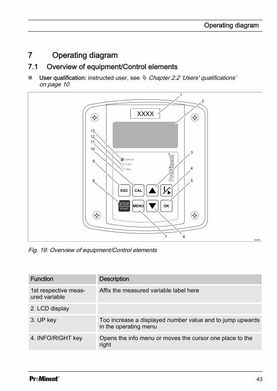
Fig. 19: Overview of equipment/Control elements
Function Description
1st respective meas‐ured variable
Affix the measured variable label here
2. LCD display
3. UP key Too increase a displayed number value and to jump upwardsin the operating menu
4. INFO/RIGHT key Opens the info menu or moves the cursor one place to theright
Operating diagram
43
Function Description
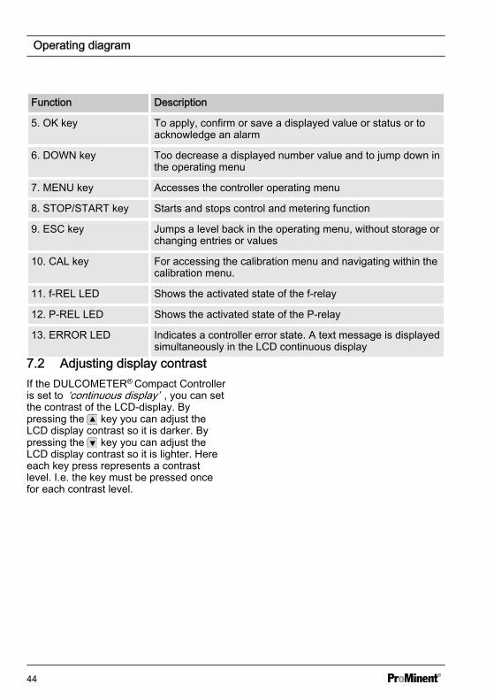
5. OK key To apply, confirm or save a displayed value or status or toacknowledge an alarm
6. DOWN key Too decrease a displayed number value and to jump down inthe operating menu
7. MENU key Accesses the controller operating menu
8. STOP/START key Starts and stops control and metering function
9. ESC key Jumps a level back in the operating menu, without storage orchanging entries or values
10. CAL key For accessing the calibration menu and navigating within thecalibration menu.
11. f-REL LED Shows the activated state of the f-relay
12. P-REL LED Shows the activated state of the P-relay
13. ERROR LED Indicates a controller error state. A text message is displayedsimultaneously in the LCD continuous display
7.2 Adjusting display contrastIf the DULCOMETER® Compact Controlleris set to ‘continuous display’ , you can setthe contrast of the LCD-display. Bypressing the key you can adjust theLCD display contrast so it is darker. Bypressing the key you can adjust theLCD display contrast so it is lighter. Hereeach key press represents a contrastlevel. I.e. the key must be pressed oncefor each contrast level.
Operating diagram
44
7.3 Continuous display
A0285
1
2
345
6
7
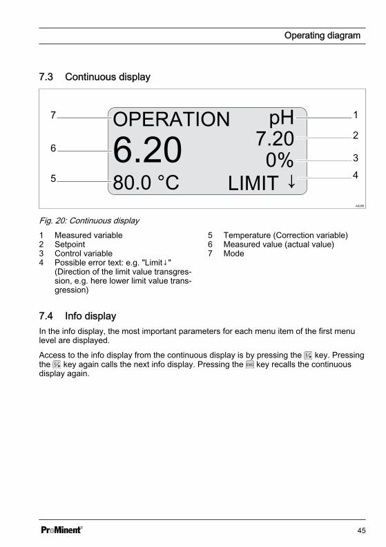
Fig. 20: Continuous display1 Measured variable2 Setpoint3 Control variable4 Possible error text: e.g. "Limit↓"
(Direction of the limit value transgres‐sion, e.g. here lower limit value trans‐gression)
5 Temperature (Correction variable)6 Measured value (actual value)7 Mode
7.4 Info displayIn the info display, the most important parameters for each menu item of the first menulevel are displayed.
Access to the info display from the continuous display is by pressing the key. Pressingthe key again calls the next info display. Pressing the key recalls the continuousdisplay again.
Operating diagram
45

A0284
OPERATION pH
6.2025.0 °C
7.200%
LIMIT ↓
LIMITSLIMIT↑= 7.80pHLIMIT↓= 6.50pH
SENSOR: pHTEMP: auto
VOLTAGE=170.8 mVGLASSRES=567MΩ
P-REL: alarmmA OUT: meas val
CONTROLPUMP: dosing↓TYPE: PBASIC= 0%
INPUT
CONTACT: pause
OUTPUT
f-REL: dosing
MEASLASTERROR
VERSIONS
NO PROBE 135 min
SW-VER 01.00.00.00
SN 2366733289 (05)
mA Range↑ 88 minmV Range↑136 min
BL-VER 03.02.02.01
BOARDTEMP= 50 °C
Fig. 21: Info displayUsing the key you can jump from the currently displayed info display directly to theselection menu of this info display.
Using the key you can jump back to the info display.
Info display "MEAS"The "MEAS" info display shows the following measured values:– [VOLTAGE]: currently measured sensor mV value– [GLASSRES]: measured glass resistance of connected pH sensors for media
temperatures of 15 °C to 80 °C. The displayed value is only valid when usedwith ProMinent pH sensors
– [BOARDTEMP]: Current housing interior temperature
Operating diagram
46
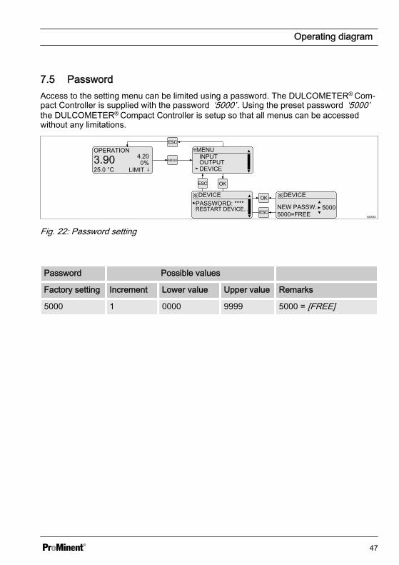
7.5 PasswordAccess to the setting menu can be limited using a password. The DULCOMETER® Com‐pact Controller is supplied with the password ‘5000’ . Using the preset password ‘5000’the DULCOMETER® Compact Controller is setup so that all menus can be accessedwithout any limitations.
A0353
OPERATION
3.9025.0 °C
4.200%
LIMIT ↓MENU
≡MENU
DEVICEOUTPUTINPUT
※DEVICEPASSWORD: ****
※DEVICE
NEW PASSW. 5000=FREE
RESTART DEVICE... 5000
Fig. 22: Password setting
Password Possible values
Factory setting Increment Lower value Upper value Remarks
5000 1 0000 9999 5000 = [FREE]
Operating diagram
47

8 Operating menus for the measured variables pH and ORPn User qualification: instructed user, see Ä Chapter 2.2 ‘Users' qualifications’
on page 10
A0276
OPERATION pH
6.2080.0 °C
7.200%
LIMIT ↓
≡MENU
MENU
LIMITSCONTROLINPUT
LIMITS SETUP
≡MENULIMITSCONTROLINPUT
≡MENULIMITSCONTROLINPUT
≡MENU
OUTPUT
CONTROLINPUT
≡MENU
DEVICEOUTPUTINPUT
ESC
ESC
ESC
ESC
ESC
CONTROL SETUP
INPUT SETUP
OUTPUT SETUP
DEVICE SETUP
STOP pH
6.2080.0 °C
7.200%
LIMIT ↓STARTSTOPCAL pH CAL
ESC
Fig. 23: Operating menu overview8.1 pH sensor calibration (CAL)
Correct sensor operation– Correct measuring and metering is only possible if the sensor is working per‐
fectly– Observe the sensor operating instructions– The carrying out of a 2-point calibration is strongly recommended and is to be
preferred to a single point calibration
Operating menus for the measured variables pH and ORP
48
During calibration, the DULCOMETER® Compact Controller sets the control outputs to‘0’ . Exception to this: a basic load or a manual control variable has been set. Thisremains active. The mA standard signal output is frozen.
When calibration/testing has been completed successfully, all of the error checks relatingto the reading are restarted. The DULCOMETER® Compact Controller saves all thedetermined data for zero point and slope when the calibration is successful.
Used bufferDispose of the used buffer solution. Related info: see buffer solution safety datasheet.
Setting Possible values
Startingvalue
Increment Lower value Upper value Remarks
Buffer tem‐perature
Measuredvalue
0.1 0 120 °C The tem‐perature canonly beadjustedunder
‘TEMP’‘auto’or
‘manual’
Buffervalues
Start value =
7.00 pH(ZERO)
4.00 pH(SLOPE)
0.01 pH 0.00 pH 14.00 pH Limit valueZERO = 6..8pH
Limit valueSLOPE = <6 pH; > 8 pH
Operating menus for the measured variables pH and ORP
49
2-Point Calibration
A0278
OPERATION pH
6.2025.0 °C
7.200%
LIMIT ↓
CAL pH
SLOPE 59.16 mV/pH OKCAL=START
ZERO 0.00 mV OK
CAL pH
TEMP= 025.0 °CBUFFER
CAL pH 7
7.00 pHCAL=START
CAL pH 7.00SENSOR = 3 mV
WAIT...
CAL pH 4/9
04.00 pHCAL=START
CAL pH 4.00SENSOR = 167 mV
WAIT...
CAL pH ZERO -3.37mV OK
CAL=ACCEPTSLOPE 56,67 mV/pH OK
Zero (6,00...8,00 pH)
SLOPE (<6,00 pH; >8,00 pH)
Fig. 24: 2-Point calibration pH sensor
Operating menus for the measured variables pH and ORP
50
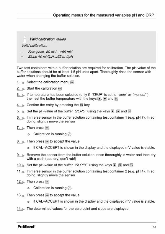
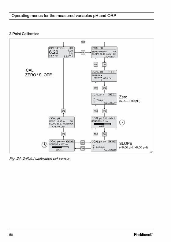
Valid calibration valuesValid calibration:– Zero point -60 mV…+60 mV– Slope 40 mV/pH…65 mV/pH
Two test containers with a buffer solution are required for calibration. The pH value of thebuffer solutions should be at least 1.5 pH units apart. Thoroughly rinse the sensor withwater when changing the buffer solution.
1. Select the calibration menu
2. Start the calibration
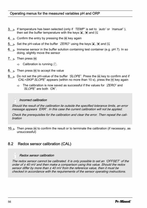
3. If temperature has been selected (only if ‘TEMP’ is set to ‘auto’ or ‘manual’ ),then set the buffer temperature with the keys , and
4. Confirm the entry by pressing the key
5. Set the pH-value of the buffer ‘ZERO’ using the keys , and
6. Immerse sensor in the buffer solution containing test container 1 (e.g. pH 7). In sodoing, slightly move the sensor
7. Then press
ð Calibration is running .
8. Then press to accept the value
ð if CAL=ACCEPT is shown in the display and the displayed mV value is stable.
9. Remove the sensor from the buffer solution, rinse thoroughly in water and then drywith a cloth (pad dry, don't rub!)
10. Set the pH-value of the buffer ‘SLOPE’ using the keys , and
11. Immerse sensor in the buffer solution containing test container 2 (e.g. pH 4). In sodoing, slightly move the sensor
12. Then press
ð Calibration is running .
13. Then press to accept the value
ð if CAL=ACCEPT is shown in the display and the displayed mV value is stable.
14. The determined values for the zero point and slope are displayed
Operating menus for the measured variables pH and ORP
51

ð The calibration is now saved as successful if the values for ‘ZERO’ and‘SLOPE’ are both ‘OK’ .
Incorrect calibrationShould the result of the calibration lie outside the specified tolerance limits, an errormessage appears ‘ERR’ . In this case the current calibration will not be applied.Check the prerequisites for the calibration and clear the error. Then repeat the cali‐bration
15. Then press to confirm the result or to terminate the calibration (if necessary, asunsuccessful)
Operating menus for the measured variables pH and ORP
52
1-Point slope calibration
A0354
OPERATION pH
6.2025.0 °C
7.200%
LIMIT ↓
CAL pH
SLOPE 59.16 mV/pH OKCAL=START
ZERO 0.00 mV OK
CAL pH
TEMP= 025.0 °CBUFFER
CAL pH 7
7.00 pHCAL=START
CAL pH 7.00SENSOR = 3 mV
CAL=SKIP ZERO
CAL pH 4/9
04.00 pHCAL=START
CAL pH 4.00SENSOR = 167 mV
CAL pH ZERO -3.37mV OK
CAL=ACCEPTSLOPE 56,67 mV/pH OK
WAIT...SLOPE (<6,00 pH; >8,00 pH)
Fig. 25: Single point slope calibration
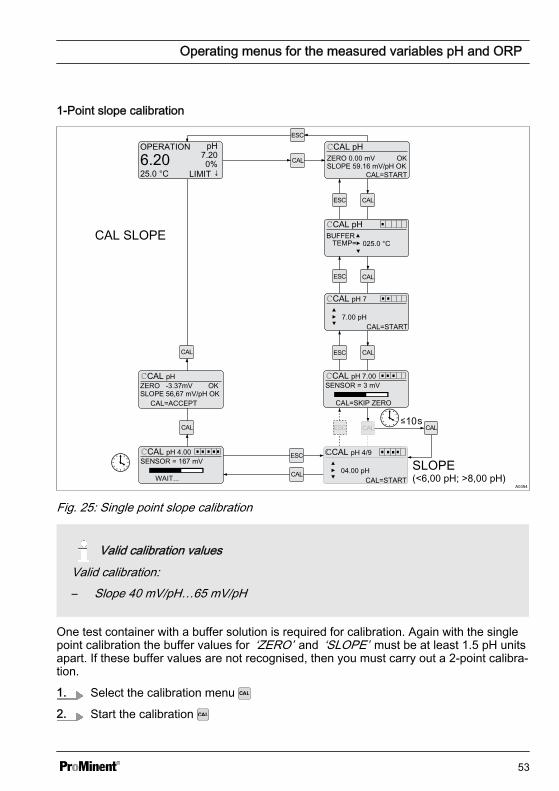
Valid calibration valuesValid calibration:– Slope 40 mV/pH…65 mV/pH
One test container with a buffer solution is required for calibration. Again with the singlepoint calibration the buffer values for ‘ZERO’ and ‘SLOPE’ must be at least 1.5 pH unitsapart. If these buffer values are not recognised, then you must carry out a 2-point calibra‐tion.
1. Select the calibration menu
2. Start the calibration
Operating menus for the measured variables pH and ORP
53
3. If temperature has been selected (only if ‘TEMP’ is set to ‘auto’ or ‘manual’ ),then set the buffer temperature with the keys , and
4. Confirm the entry by pressing the key or key
5. Do not set the pH-value of the buffer ‘ZERO’ . Press the key to confirm and if‘CAL=SKIP ZERO’ appears (within no more than 10 s), press the key again
ð You have skipped the zero point calibration and are now in the slope calibra‐tion screen
6. Set the pH-value of the buffer ‘SLOPE’ using the keys , and
7. Immerse sensor in the buffer solution containing test container (e.g. pH 4). In sodoing, slightly move the sensor
8. Then press
ð Calibration is running .
9. Then press to accept the value
10. The determined values for the zero point and slope are displayed
ð The calibration is now saved as successful if the values for ‘ZERO’ and‘SLOPE’ are both ‘OK’ .
Incorrect calibrationShould the result of the calibration lie outside the specified tolerance limits, an errormessage appears ‘ERR’ . In this case the current calibration will not be applied.Check the prerequisites for the calibration and clear the error. Then repeat the cali‐bration
11. Then press to confirm the result or to terminate the calibration (if necessary, asunsuccessful)
Operating menus for the measured variables pH and ORP
54
Single point zero point calibration
A0355
OPERATION pH
6.2025.0 °C
7.200%
LIMIT ↓
CAL pH
SLOPE 59.16 mV/pH OKCAL=START
ZERO 0.00 mV OK
CAL pH
TEMP= 025.0 °CBUFFER
CAL pH 7
7.00 pHCAL=START
CAL pH 7.00SENSOR = 3 mV
WAIT...
CAL pH 4/9
04.00 pHCAL=START
CAL pH 4.00SENSOR = 167 mV
CAL=SKIP SLOPE
CAL pH ZERO -3.37mV OK
CAL=ACCEPTSLOPE 56,67 mV/pH OK
CALCAL
Zero (6,00...8,00 pH)
Fig. 26: Single point zero point calibration
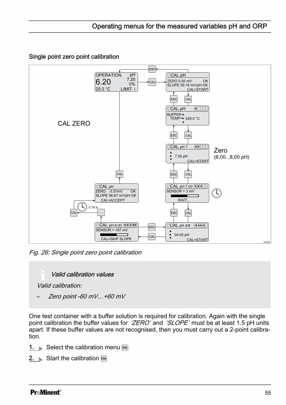
Valid calibration valuesValid calibration:– Zero point -60 mV…+60 mV
One test container with a buffer solution is required for calibration. Again with the singlepoint calibration the buffer values for ‘ZERO’ and ‘SLOPE’ must be at least 1.5 pH unitsapart. If these buffer values are not recognised, then you must carry out a 2-point calibra‐tion.
1. Select the calibration menu
2. Start the calibration
Operating menus for the measured variables pH and ORP
55
3. If temperature has been selected (only if ‘TEMP’ is set to ‘auto’ or ‘manual’ ),then set the buffer temperature with the keys , and
4. Confirm the entry by pressing the key again
5. Set the pH-value of the buffer ‘ZERO’ using the keys , and
6. Immerse sensor in the buffer solution containing test container (e.g. pH 7). In sodoing, slightly move the sensor
7. Then press
ð Calibration is running .
8. Then press to accept the value
9. Do not set the pH-value of the buffer ‘SLOPE’ . Press the key to confirm and if‘CAL=SKIP SLOPE’ appears (within no more than 10 s), press the key again
ð The calibration is now saved as successful if the values for ‘ZERO’ and‘SLOPE’ are both ‘OK’ .
Incorrect calibrationShould the result of the calibration lie outside the specified tolerance limits, an errormessage appears ‘ERR’ . In this case the current calibration will not be applied.Check the prerequisites for the calibration and clear the error. Then repeat the cali‐bration
10. Then press to confirm the result or to terminate the calibration (if necessary, asunsuccessful)
8.2 Redox sensor calibration (CAL)
Redox sensor calibrationThe redox sensor cannot be calibrated. It is only possible to set an ‘OFFSET’ of theorder of ± 40 mV and then make a comparison using this value. Should the redoxsensor differ by more than ± 40 mV from the reference value, then it must bechecked in accordance with the requirements of the sensor operating instructions.
Operating menus for the measured variables pH and ORP
56
Correct sensor operation– Correct measuring and metering is only possible if the sensor is working per‐
fectly– Observe the sensor operating instructions
During the calibration: the DULCOMETER® Compact Controller sets the control outputsto ‘0’ . Exception to this: a basic load or a manual control variable has been set. Thisremains active. The mA standard signal output is frozen.
Used bufferDispose of the used buffer solution. Related info: see buffer solution safety datasheet.
A0356
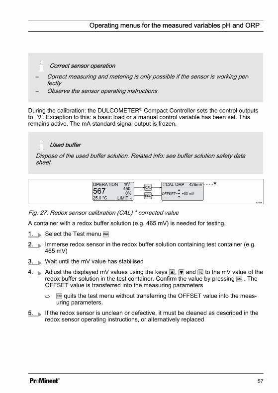
Fig. 27: Redox sensor calibration (CAL) * corrected valueA container with a redox buffer solution (e.g. 465 mV) is needed for testing.
1. Select the Test menu
2. Immerse redox sensor in the redox buffer solution containing test container (e.g.465 mV)
3. Wait until the mV value has stabilised
4. Adjust the displayed mV values using the keys , and to the mV value of theredox buffer solution in the test container. Confirm the value by pressing . TheOFFSET value is transferred into the measuring parameters
ð quits the test menu without transferring the OFFSET value into the meas‐uring parameters.
5. If the redox sensor is unclean or defective, it must be cleaned as described in theredox sensor operating instructions, or alternatively replaced
Operating menus for the measured variables pH and ORP
57
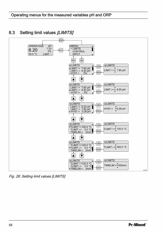
8.3 Setting limit values [LIMITS]
A0279
OPERATION pH
6.2025.0 °C
7.200%
LIMIT ↓
MENU
≡MENULIMITSCONTROLINPUT
※LIMITS
LIMIT↓= 6.50 pHLIMIT↑= 7.80 pH
HYST.= 5%
※LIMITS
7.80 pH
※LIMITS
LIMIT↑=
6.50 pH
※LIMITS
LIMIT↓= 6.50 pHLIMIT↑= 7.80 pH
※LIMITS
0,28 pH
※LIMITSLIMIT↓= 6.50 pHLIMIT↑= 7.80 pH
※LIMITS
TLIMIT↓= 0.0 °CTLIMIT↑=120.0 °C
TIMELIM.= 0min
※LIMITS
HYST.=
000.0 °C
※LIMITS
TLIMIT↓= 0.0 °CTLIMIT↑=120.0 °C
TIMELIM.= 0min
※LIMITS
TIMELIM.= 000min
LIMIT↓=
TLIMIT↓=
HYST.= 5%
HYST.= 0,28 pH
※LIMITS
TLIMIT↓= 0.0 °CTLIMIT↑=120.0 °C
TIMELIM.= 0min
※LIMITS
120.0 °CTLIMIT↑=
Fig. 28: Setting limit values [LIMITS]
Operating menus for the measured variables pH and ORP
58
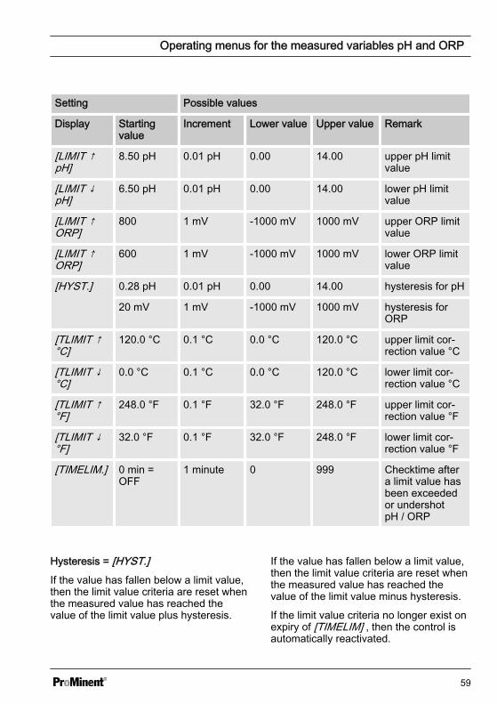
Setting Possible values
Display Startingvalue
Increment Lower value Upper value Remark
[LIMIT ↑pH]
8.50 pH 0.01 pH 0.00 14.00 upper pH limitvalue
[LIMIT ↓pH]
6.50 pH 0.01 pH 0.00 14.00 lower pH limitvalue
[LIMIT ↑ORP]
800 1 mV -1000 mV 1000 mV upper ORP limitvalue
[LIMIT ↑ORP]
600 1 mV -1000 mV 1000 mV lower ORP limitvalue
[HYST.] 0.28 pH 0.01 pH 0.00 14.00 hysteresis for pH
20 mV 1 mV -1000 mV 1000 mV hysteresis forORP
[TLIMIT ↑°C]
120.0 °C 0.1 °C 0.0 °C 120.0 °C upper limit cor‐rection value °C
[TLIMIT ↓°C]
0.0 °C 0.1 °C 0.0 °C 120.0 °C lower limit cor‐rection value °C
[TLIMIT ↑°F]
248.0 °F 0.1 °F 32.0 °F 248.0 °F upper limit cor‐rection value °F
[TLIMIT ↓°F]
32.0 °F 0.1 °F 32.0 °F 248.0 °F lower limit cor‐rection value °F
[TIMELIM.] 0 min =OFF
1 minute 0 999 Checktime aftera limit value hasbeen exceededor undershotpH / ORP
Hysteresis = [HYST.]If the value has fallen below a limit value,then the limit value criteria are reset whenthe measured value has reached thevalue of the limit value plus hysteresis.
If the value has fallen below a limit value,then the limit value criteria are reset whenthe measured value has reached thevalue of the limit value minus hysteresis.
If the limit value criteria no longer exist onexpiry of [TIMELIM] , then the control isautomatically reactivated.
Operating menus for the measured variables pH and ORP
59
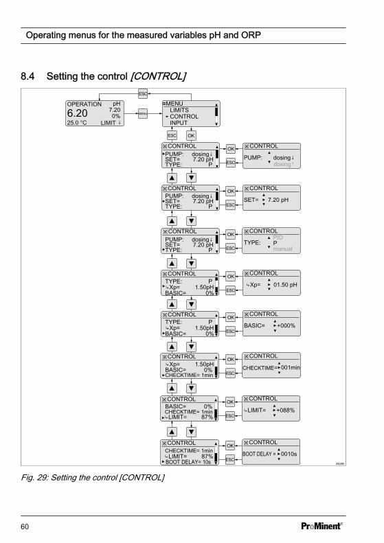
8.4 Setting the control [CONTROL]
A0280
OPERATION pH
6.2025.0 °C
7.200%
LIMIT ↓MENU
≡MENULIMITSCONTROLINPUT
※CONTROLPUMP: dosing↓SET= 7.20 pHTYPE: P
※CONTROL
PUMP: dosing↓
※CONTROL
SET= 7.20 pH
※CONTROL
※CONTROL
TYPE: P
※CONTROL
※CONTROL ※CONTROL
01.50 pH
※CONTROL ※CONTROL
BASIC= +000%
PUMP: dosing↓SET= 7.20 pHTYPE: P
PUMP: dosing↓SET= 7.20 pHTYPE: P
TYPE: PXp= 1.50pHBASIC= 0%
Xp=
TYPE: PXp= 1.50pHBASIC= 0%
※CONTROL ※CONTROL
CHECKTIME= 001minCHECKTIME= 1min
Xp= 1.50pHBASIC= 0%
※CONTROL ※CONTROL
LIMIT= +088%CHECKTIME= 1minLIMIT= 87%
BASIC= 0%
dosing↑
PID
manual
※CONTROL ※CONTROL
BOOT DELAY = 0010sCHECKTIME= 1minLIMIT= 87%BOOT DELAY= 10s
Fig. 29: Setting the control [CONTROL]
Operating menus for the measured variables pH and ORP
60
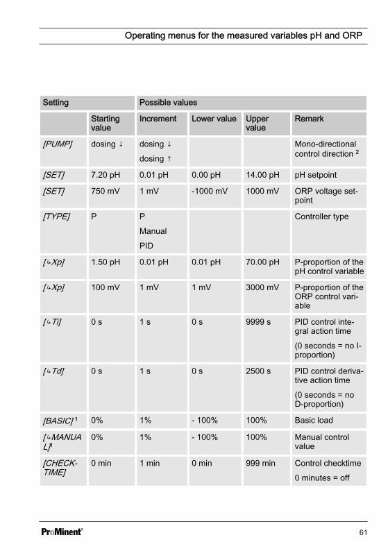
Setting Possible values
Startingvalue
Increment Lower value Uppervalue
Remark
[PUMP] dosing ↓ dosing ↓
dosing ↑
Mono-directionalcontrol direction 2
[SET] 7.20 pH 0.01 pH 0.00 pH 14.00 pH pH setpoint
[SET] 750 mV 1 mV -1000 mV 1000 mV ORP voltage set‐point
[TYPE] P P
Manual
PID
Controller type
[Xp] 1.50 pH 0.01 pH 0.01 pH 70.00 pH P-proportion of thepH control variable
[Xp] 100 mV 1 mV 1 mV 3000 mV P-proportion of theORP control vari‐able
[Ti] 0 s 1 s 0 s 9999 s PID control inte‐gral action time
(0 seconds = no I-proportion)
[Td] 0 s 1 s 0 s 2500 s PID control deriva‐tive action time
(0 seconds = noD-proportion)
[BASIC] 1 0% 1% - 100% 100% Basic load
[MANUAL]1
0% 1% - 100% 100% Manual controlvalue
[CHECK‐TIME]
0 min 1 min 0 min 999 min Control checktime
0 minutes = off
Operating menus for the measured variables pH and ORP
61
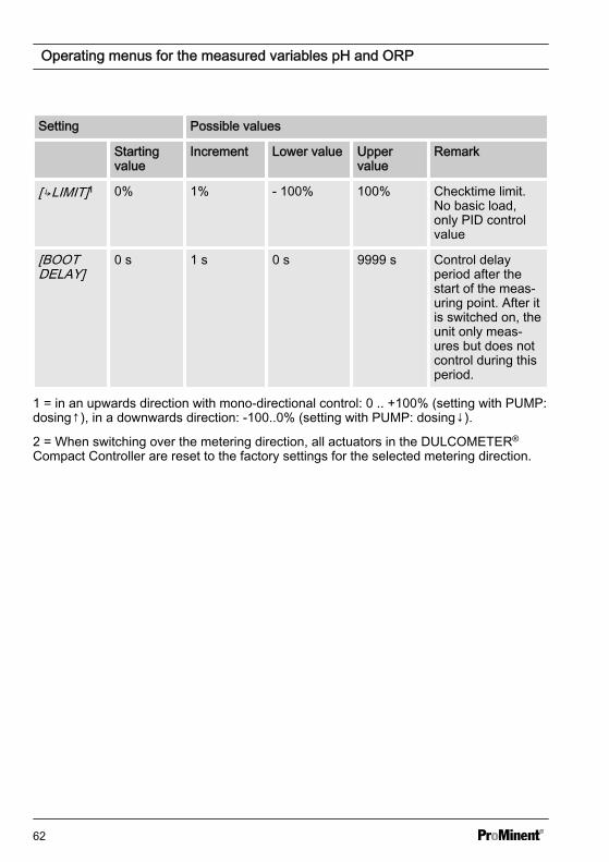
Setting Possible values
Startingvalue
Increment Lower value Uppervalue
Remark
[LIMIT]1 0% 1% - 100% 100% Checktime limit.No basic load,only PID controlvalue
[BOOTDELAY]
0 s 1 s 0 s 9999 s Control delayperiod after thestart of the meas‐uring point. After itis switched on, theunit only meas‐ures but does notcontrol during thisperiod.
1 = in an upwards direction with mono-directional control: 0 .. +100% (setting with PUMP:dosing↑), in a downwards direction: -100..0% (setting with PUMP: dosing↓).
2 = When switching over the metering direction, all actuators in the DULCOMETER®
Compact Controller are reset to the factory settings for the selected metering direction.
Operating menus for the measured variables pH and ORP
62
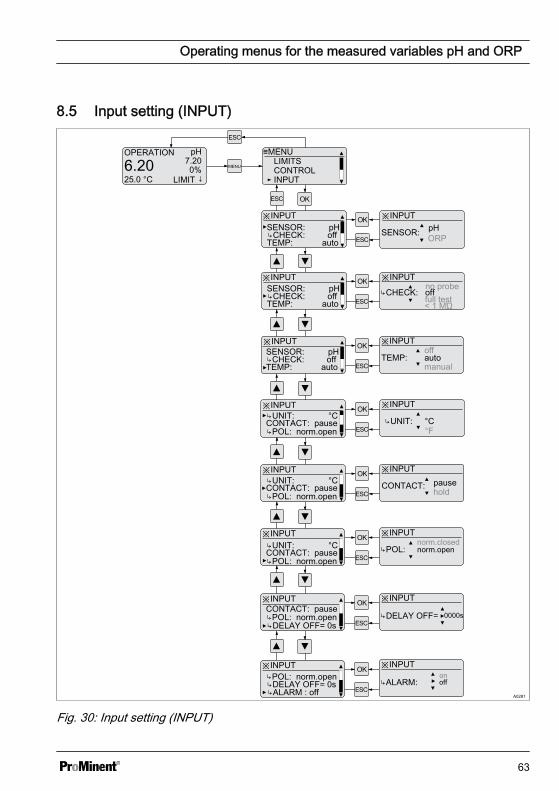
8.5 Input setting (INPUT)
A0281
OPERATION pH
6.2025.0 °C
7.200%
LIMIT ↓MENU
≡MENULIMITSCONTROLINPUT
※INPUTSENSOR: pHCHECK: offTEMP: auto
※INPUT
SENSOR: pH
※INPUT※INPUT
※INPUT
TEMP: auto
※INPUT
※INPUT ※INPUT
°C
※INPUT ※INPUT
CONTACT: pause
CONTACT: pauseUNIT: °C UNIT:
※INPUT ※INPUT
SENSOR: pH
TEMP: auto
SENSOR: pH
TEMP: auto
ORP
CHECK: off
off
manual
POL: norm.open
CONTACT: pauseUNIT: °C
POL: norm.open
CONTACT: pauseUNIT: °C
POL: norm.open
°F
hold
POL: norm.opennorm.closed
※INPUT ※INPUT CONTACT: pausePOL: norm.openDELAY OFF= 0s
DELAY OFF= 0000s
CHECK: off
CHECK: off
full testno probe
< 1 MΏ
※INPUT ※INPUT POL: norm.openDELAY OFF= 0s ALARM: offALARM : off
on
Fig. 30: Input setting (INPUT)
Operating menus for the measured variables pH and ORP
63
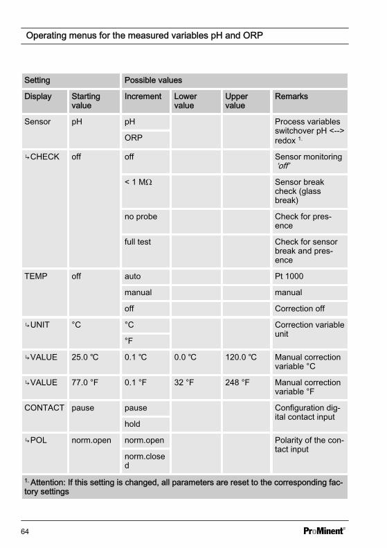
Setting Possible values
Display Startingvalue
Increment Lowervalue
Uppervalue
Remarks
Sensor pH pH Process variablesswitchover pH <-->redox 1.ORP
CHECK off off Sensor monitoring‘off’
< 1 MΩ Sensor breakcheck (glassbreak)
no probe Check for pres‐ence
full test Check for sensorbreak and pres‐ence
TEMP off auto Pt 1000
manual manual
off Correction off
UNIT °C °C Correction variableunit
°F
VALUE 25.0 0.1 0.0 120.0 Manual correctionvariable °C
VALUE 77.0 °F 0.1 °F 32 °F 248 °F Manual correctionvariable °F
CONTACT pause pause Configuration dig‐ital contact input
hold
POL norm.open norm.open Polarity of the con‐tact input
norm.closed
1. Attention: If this setting is changed, all parameters are reset to the corresponding fac‐tory settings
Operating menus for the measured variables pH and ORP
64
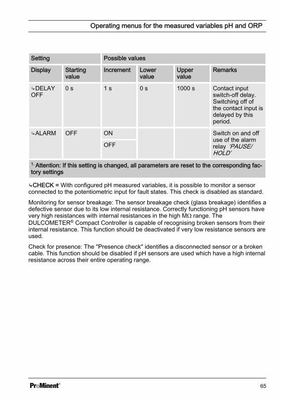
Setting Possible values
Display Startingvalue
Increment Lowervalue
Uppervalue
Remarks
DELAYOFF
0 s 1 s 0 s 1000 s Contact inputswitch-off delay.Switching off ofthe contact input isdelayed by thisperiod.
ALARM OFF ON Switch on and offuse of the alarmrelay ‘PAUSE/HOLD’
OFF
1. Attention: If this setting is changed, all parameters are reset to the corresponding fac‐tory settings
CHECK = With configured pH measured variables, it is possible to monitor a sensorconnected to the potentiometric input for fault states. This check is disabled as standard.
Monitoring for sensor breakage: The sensor breakage check (glass breakage) identifies adefective sensor due to its low internal resistance. Correctly functioning pH sensors havevery high resistances with internal resistances in the high MΩ range. TheDULCOMETER® Compact Controller is capable of recognising broken sensors from theirinternal resistance. This function should be deactivated if very low resistance sensors areused.
Check for presence: The "Presence check" identifies a disconnected sensor or a brokencable. This function should be disabled if pH sensors are used which have a high internalresistance across their entire operating range.
Operating menus for the measured variables pH and ORP
65
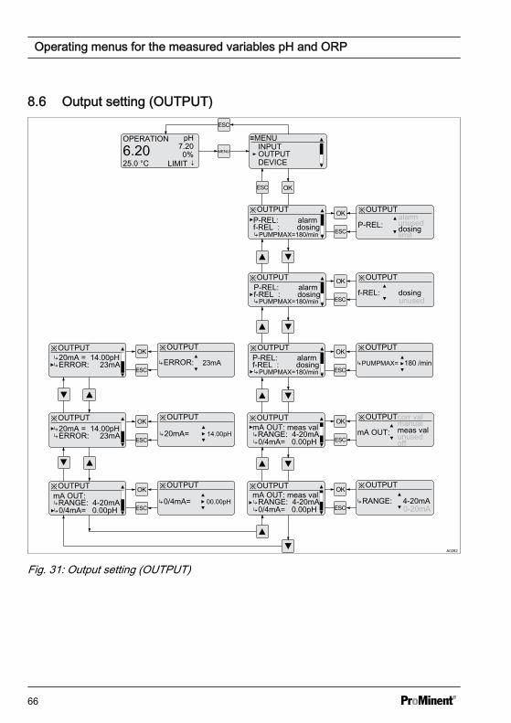
8.6 Output setting (OUTPUT)
A0282
OPERATION pH
6.2025.0 °C
7.200%
LIMIT ↓MENU
≡MENU
DEVICEOUTPUTINPUT
※OUTPUTP-REL: alarm
PUMPMAX=180/min
※OUTPUT
P-REL:alarm
※OUTPUT※OUTPUT
※OUTPUT※OUTPUT
※OUTPUT ※OUTPUTmeas val
※OUTPUT ※OUTPUT
mA OUT: meas val mA OUT:
※OUTPUT ※OUTPUT
0/4mA= 0.00pH20mA = 14.00pH
※OUTPUT ※OUTPUT
0/4mA= 00.00pH
f-REL : dosing
PUMPMAX=180/min
PUMPMAX=180/min
f-REL: dosing
PUMPMAX= 180 /min
RANGE: 4-20mA
mA OUT: meas val
0/4mA= 0.00pHRANGE: 4-20mA
mA OUT:
0/4mA= 0.00pHRANGE: 4-20mA RANGE: 4-20mA
※OUTPUT ※OUTPUT
ERROR: 23mA
ERROR: 23mA
20mA = 14.00pHERROR: 23mA
20mA= 14.00pH
P-REL: alarmf-REL : dosing
P-REL: alarmf-REL : dosing
limitdosingunused
unused
unusedoff
manualcorr val
0-20mA
Fig. 31: Output setting (OUTPUT)
Operating menus for the measured variables pH and ORP
66
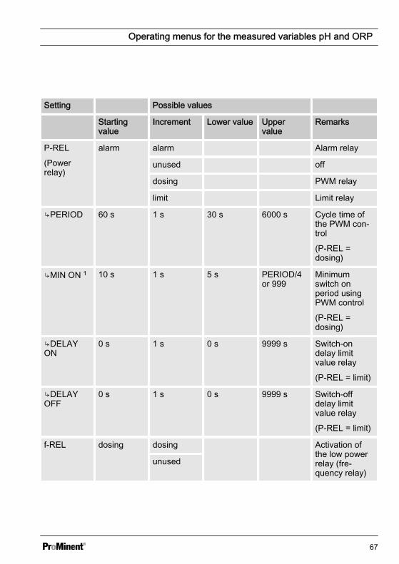
Setting Possible values
Startingvalue
Increment Lower value Uppervalue
Remarks
P-REL
(Powerrelay)
alarm alarm Alarm relay
unused off
dosing PWM relay
limit Limit relay
PERIOD 60 s 1 s 30 s 6000 s Cycle time ofthe PWM con‐trol
(P-REL =dosing)
MIN ON 1 10 s 1 s 5 s PERIOD/4or 999
Minimumswitch onperiod usingPWM control
(P-REL =dosing)
DELAYON
0 s 1 s 0 s 9999 s Switch-ondelay limitvalue relay
(P-REL = limit)
DELAYOFF
0 s 1 s 0 s 9999 s Switch-offdelay limitvalue relay
(P-REL = limit)
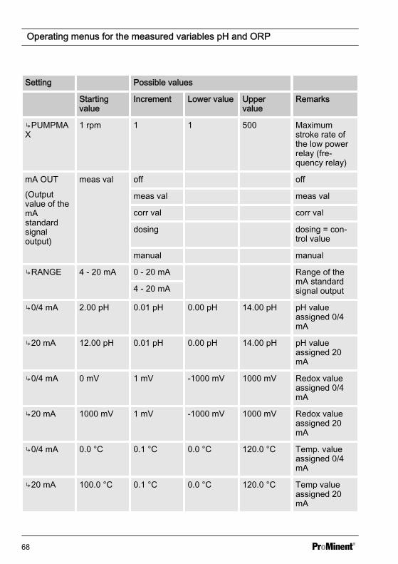
f-REL dosing dosing Activation ofthe low powerrelay (fre‐quency relay)
unused
Operating menus for the measured variables pH and ORP
67
Setting Possible values
Startingvalue
Increment Lower value Uppervalue
Remarks
PUMPMAX
1 rpm 1 1 500 Maximumstroke rate ofthe low powerrelay (fre‐quency relay)
mA OUT
(Outputvalue of themAstandardsignaloutput)
meas val off off
meas val meas val
corr val corr val
dosing dosing = con‐trol value
manual manual
RANGE 4 - 20 mA 0 - 20 mA Range of themA standardsignal output4 - 20 mA
0/4 mA 2.00 pH 0.01 pH 0.00 pH 14.00 pH pH valueassigned 0/4mA
20 mA 12.00 pH 0.01 pH 0.00 pH 14.00 pH pH valueassigned 20mA
0/4 mA 0 mV 1 mV -1000 mV 1000 mV Redox valueassigned 0/4mA
20 mA 1000 mV 1 mV -1000 mV 1000 mV Redox valueassigned 20mA
0/4 mA 0.0 °C 0.1 °C 0.0 °C 120.0 °C Temp. valueassigned 0/4mA
20 mA 100.0 °C 0.1 °C 0.0 °C 120.0 °C Temp valueassigned 20mA
Operating menus for the measured variables pH and ORP
68
Setting Possible values
Startingvalue
Increment Lower value Uppervalue
Remarks
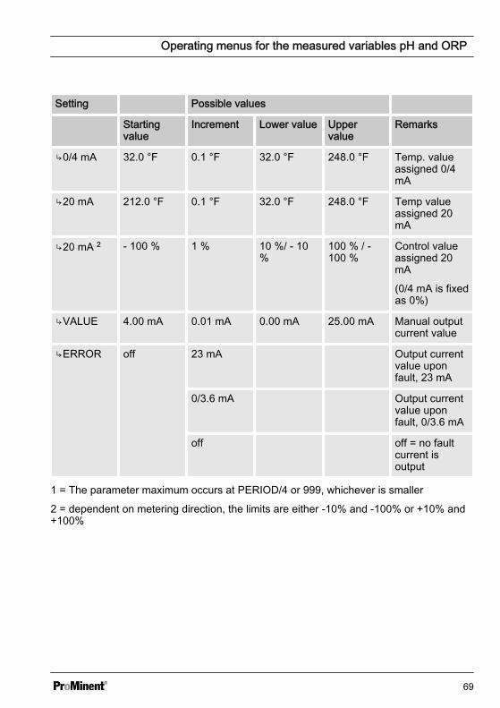
0/4 mA 32.0 °F 0.1 °F 32.0 °F 248.0 °F Temp. valueassigned 0/4mA
20 mA 212.0 °F 0.1 °F 32.0 °F 248.0 °F Temp valueassigned 20mA
20 mA 2 - 100 % 1 % 10 %/ - 10%
100 % / -100 %
Control valueassigned 20mA
(0/4 mA is fixedas 0%)
VALUE 4.00 mA 0.01 mA 0.00 mA 25.00 mA Manual outputcurrent value
ERROR off 23 mA Output currentvalue uponfault, 23 mA
0/3.6 mA Output currentvalue uponfault, 0/3.6 mA
off off = no faultcurrent isoutput
1 = The parameter maximum occurs at PERIOD/4 or 999, whichever is smaller
2 = dependent on metering direction, the limits are either -10% and -100% or +10% and+100%
Operating menus for the measured variables pH and ORP
69
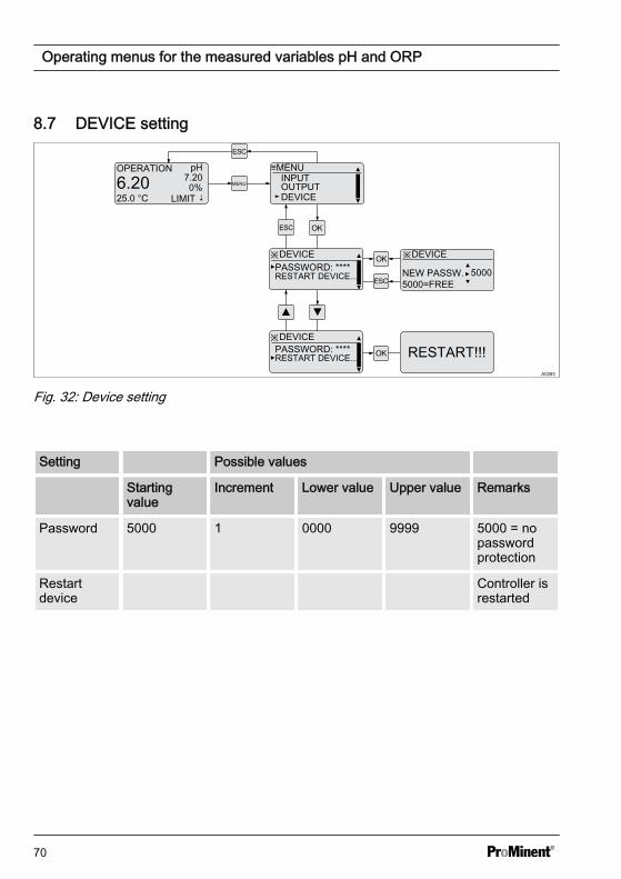
8.7 DEVICE setting
A0283
OPERATION pH
6.2025.0 °C
7.200%
LIMIT ↓MENU
≡MENU
DEVICEOUTPUTINPUT
※DEVICEPASSWORD: ****
※DEVICE
NEW PASSW. 5000=FREE
※DEVICE
RESTART DEVICE...
PASSWORD: ****RESTART DEVICE... RESTART!!!
5000
Fig. 32: Device setting
Setting Possible values
Startingvalue
Increment Lower value Upper value Remarks
Password 5000 1 0000 9999 5000 = nopasswordprotection
Restartdevice
Controller isrestarted
Operating menus for the measured variables pH and ORP
70
9 Control parameters and functionsn User qualification: trained user, see
Ä Chapter 2.2 ‘Users' qualifications’on page 10
9.1 DULCOMETER® CompactController function states
DULCOMETER® Compact Controllerfunction states have the following priority:
n 1. ‘STOP’n 2. ‘PAUSE/HOLD’n 3. ‘CAL’ (calibration)n 4. ‘OPERATION’ (normal mode)
"CAL" (calibration) peculiarities
n Control goes to basic load, mA meas‐urement outputs are frozen
n New faults are detected, howeverthey have no effect on the alarm relayor the mA output
n Detection of measurement variablerelevant faults during ‘CAL’ (calibra‐tion process) are suppressed (e.g.LIMIT↑)
"PAUSE" peculiarities
n Control is switched to 0% control vari‐able. The I-proportion is saved
n New faults are detected, howeverthey have no effect on the alarm relayor the mA output
n Special case alarm relay in ‘PAUSE’ :If activated the output relay switchesto ‘PAUSE’ (error message CON‐TACTIN)
"HOLD" peculiarities
n Control and all other outputs arefrozen
n New faults are detected, howeverthey have no effect on the alarm relayor the mA output. However the effectof already existing faults (e.g. faultcurrent) remains
n Special case alarm relay: Activation ofthe frozen alarm relay is permitted (=no alarm), if all faults have beenacknowledged or have disappeared
n Special case alarm relay in ‘HOLD’ : Ifactivated the output relay switches to‘HOLD’ (error message CON‐TACTIN)
"STOP" peculiarities
n Control OFFn New faults are detected, however
they have no effect on the alarm relayor the mA output
n The alarm relay is switched off in‘STOP’
Peculiarities of the "START" event, i.e.switching from "STOP" to "OPERATION"(normal mode)
n Fault detection starts afresh, allexisting faults are deleted
Generally applicable information
n If the cause of a fault disappears,then the fault message in the LCDfooter disappears.
n A previously existing ‘ PAUSE/HOLD’state is not influenced by starting a‘CAL’ (calibration) process. If during‘CAL’ (calibration) the functional state‘ PAUSE/HOLD’ is released, then allstates will remain frozen until the endof the ‘CAL’ (calibration) process.
Control parameters and functions
71
n If ‘CAL’ (calibration) is started whilefunctional state ‘ OPERATION’(normal mode) is active, then thefunctional state ‘ PAUSE/HOLD’ isignored until ‘CAL’ (calibration) com‐pletes. However STOP/START ispossible at any time
n An alarm can be acknowledged orremoved as follows: By clearing allfaults by pressing the key and the
key while the continuous display isvisible
Control parameters and functions
72
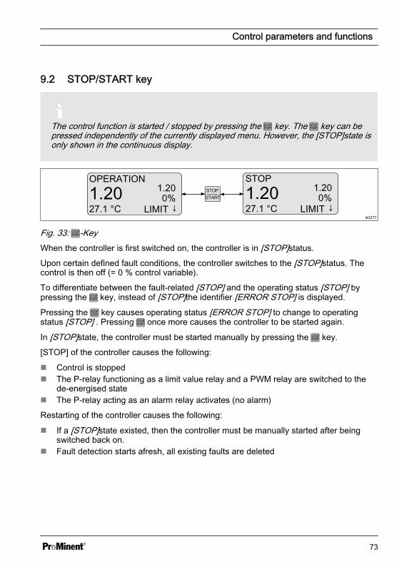
9.2 STOP/START key
The control function is started / stopped by pressing the key. The key can bepressed independently of the currently displayed menu. However, the [STOP]state isonly shown in the continuous display.
A0277
OPERATION
1.2027.1 °C
1.200%
LIMIT ↓
STOP
1.2027.1 °C
1.200%
LIMIT ↓
Fig. 33: -KeyWhen the controller is first switched on, the controller is in [STOP]status.
Upon certain defined fault conditions, the controller switches to the [STOP]status. Thecontrol is then off (= 0 % control variable).
To differentiate between the fault-related [STOP] and the operating status [STOP] bypressing the key, instead of [STOP]the identifier [ERROR STOP] is displayed.
Pressing the key causes operating status [ERROR STOP] to change to operatingstatus [STOP] . Pressing once more causes the controller to be started again.
In [STOP]state, the controller must be started manually by pressing the key.
[STOP] of the controller causes the following:
n Control is stoppedn The P-relay functioning as a limit value relay and a PWM relay are switched to the
de-energised staten The P-relay acting as an alarm relay activates (no alarm)
Restarting of the controller causes the following:
n If a [STOP]state existed, then the controller must be manually started after beingswitched back on.
n Fault detection starts afresh, all existing faults are deleted
Control parameters and functions
73
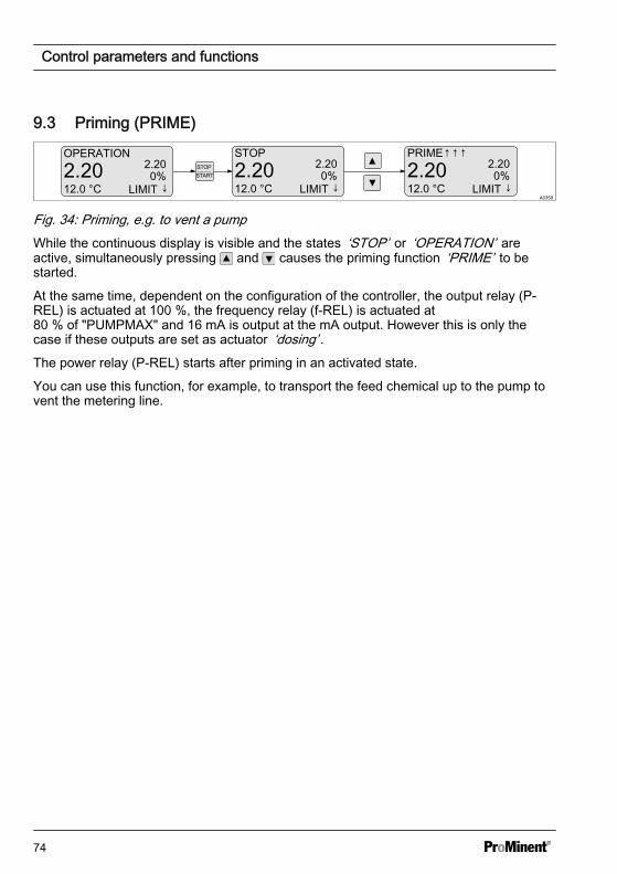
9.3 Priming (PRIME)
A0359
OPERATION
2.2012.0 °C
2.200%
LIMIT ↓
STOP
2.2012.0 °C
2.200%
LIMIT ↓
PRIME↑↑↑
2.2012.0 °C
2.200%
LIMIT ↓
Fig. 34: Priming, e.g. to vent a pumpWhile the continuous display is visible and the states ‘STOP’ or ‘OPERATION’ areactive, simultaneously pressing and causes the priming function ‘PRIME’ to bestarted.
At the same time, dependent on the configuration of the controller, the output relay (P-REL) is actuated at 100 %, the frequency relay (f-REL) is actuated at80 % of "PUMPMAX" and 16 mA is output at the mA output. However this is only thecase if these outputs are set as actuator ‘dosing’ .The power relay (P-REL) starts after priming in an activated state.
You can use this function, for example, to transport the feed chemical up to the pump tovent the metering line.
Control parameters and functions
74
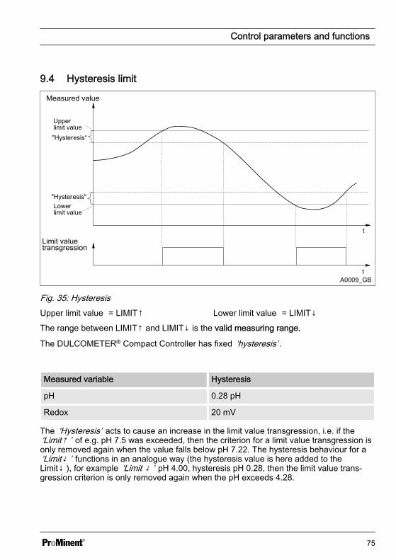
9.4 Hysteresis limit
Measured value
Limit valuetransgression
Upperlimit value
"Hysteresis"
t
t
"Hysteresis“
Lowerlimit value
A0009_GB
Fig. 35: HysteresisUpper limit value = LIMIT↑ Lower limit value = LIMIT↓
The range between LIMIT↑ and LIMIT↓ is the valid measuring range.
The DULCOMETER® Compact Controller has fixed ‘hysteresis’ .
Measured variable Hysteresis
pH 0.28 pH
Redox 20 mV
The ‘Hysteresis’ acts to cause an increase in the limit value transgression, i.e. if the‘Limit↑ ’ of e.g. pH 7.5 was exceeded, then the criterion for a limit value transgression isonly removed again when the value falls below pH 7.22. The hysteresis behaviour for a‘Limit↓ ’ functions in an analogue way (the hysteresis value is here added to theLimit↓ ), for example ‘Limit ↓ ’ pH 4.00, hysteresis pH 0.28, then the limit value trans‐gression criterion is only removed again when the pH exceeds 4.28.
Control parameters and functions
75
9.5 Temperature correction vari‐able for pH
The correction variable compensates forthe effect of the temperature of themedium on the measured value. The cor‐rection variable is the temperature of themedium to be measured. The temperatureof the medium affects the pH value to bemeasured.
Operating modes
n [off]: No temperature compensationtakes place– For measurements which do not
require temperature compensa‐tion
n [auto]: TheDULCOMETER® Compact Controllerevaluates the temperature signal ofthe connected temperature sensor– For measurements using a tem‐
perature sensor (Pt1000) (0 -120°C)
n [manual]: The temperature of themedium to be measured has to bemeasured by the user. The measuredvalue is then entered using the keys
and in the parameter ‘VALUE’in theDULCOMETER® Compact Controllerand saved using the key – For measurements where the
medium to be measured has aconstant temperature, which hasto be taken into account in thecontrol process
Control parameters and functions
76
9.6 Checkout time for measured variable and correction variable
Error text Description
LIMIT ERR Checkout time of the measured variable
TLIMITERR Checkout time of the correction variable
If upon the expiry of the checkout time, the valid measuring range is not reached, thenthe DULCOMETER® Compact Controller exhibits the following behaviour:
n LIMIT ERR: The control is switched off. An error current is emitted, provided theoutput is configured as a measured variable output
n TLIMITERR: The control is switched off. An error current is emitted, provided theoutput is configured as a correction variable output or a measured variable output
Initially the transgression of a limit is only a limit value transgression. This leads to a‘WARNING’ . Switching on the control time ‘TIMELIM’ (> 0 minutes), creates an alarmfrom the limit value transgression. In the event of a [TLIMITERR] a, the control switchesto [STOP].9.7 Checkout time control
Monitoring of the control pathThe checkout time monitors the con‐trol path. The checkout time mecha‐nism permits detection of possibledefective sensors.
Dead time determination
Each control path has a dead time. Thedead time is the time, which the controlpath requires to detect a change or addi‐tion of metered chemicals using its owninstrumentation.
You must select the checkout time so thatit is greater than the dead time. You candetermine the dead time, by operating themetering pump in manual mode and, forexample, dosing acid.
NOTICE!
Dead time determinationYou should only determine the deadtime if the current process cannot benegatively influenced by the manualmetering.
You must determine the time, which thecontrol path (i.e. the entirety of controllers,sensors, measurement water, flowgauges, etc.) requires to detect a firstchange in the measured value startingfrom the beginning of dosing. This time isthe ‘dead time’ . A safety margin, e.g.25%, must be added to this dead time.You must allocate an appropriate safetymargin for your own particular process.
The parameter ‘LIMIT’ can be used to seta limit for the control variable. If the con‐trol variable exceeds this limit value, theCHECKTIME fault is triggered (checkouttime of the control has elapsed). The con‐trol is switched to basic load and a faultcurrent output.
Control parameters and functions
77
9.8 Power relay "P-REL" as limitvalue relay
The power relay ‘P-REL’ can be config‐ured as a limit value relay. It always actonly on the measurement variable,whereby the limits are set in ‘LIMITS’ .The relay is activated upon infringementof either the top or lower limit values.
Constant checking is carried out to deter‐mine whether a limit has been infringedand if this is interrupted with the powerrelay configured ‘P-REL= limit’ for at least‘DELAY ON’ seconds, then the relay isactivated. If the limit value transgressiondisappears for at least ‘DELAY OFF’ sec‐onds, then the limit value relay is againdeactivated.
The limit value relay is deactivated imme‐diately upon: ‘STOP’ , user calibration,‘PAUSE’ and ‘HOLD’ .
Control parameters and functions
78
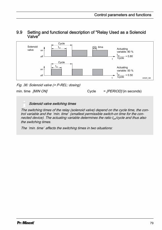
9.9 Setting and functional description of "Relay Used as a SolenoidValve"
Cyclemin. timeSolenoid
valve
off
on
t
ton
off
on
t
ton
Cycle
Actuatingvariable: 50 %ton
Cycle = 0.50
Actuatingvariable: 80 %ton
Cycle = 0.80
A0025_GB
Fig. 36: Solenoid valve (= P-REL: dosing)min. time [MIN ON] Cycle = [PERIOD] (in seconds)
Solenoid valve switching timesThe switching times of the relay (solenoid valve) depend on the cycle time, the con‐trol variable and the ‘min. time’ (smallest permissible switch-on time for the con‐nected device). The actuating variable determines the ratio ton/cycle and thus alsothe switching times.The ‘min. time’ affects the switching times in two situations:
Control parameters and functions
79
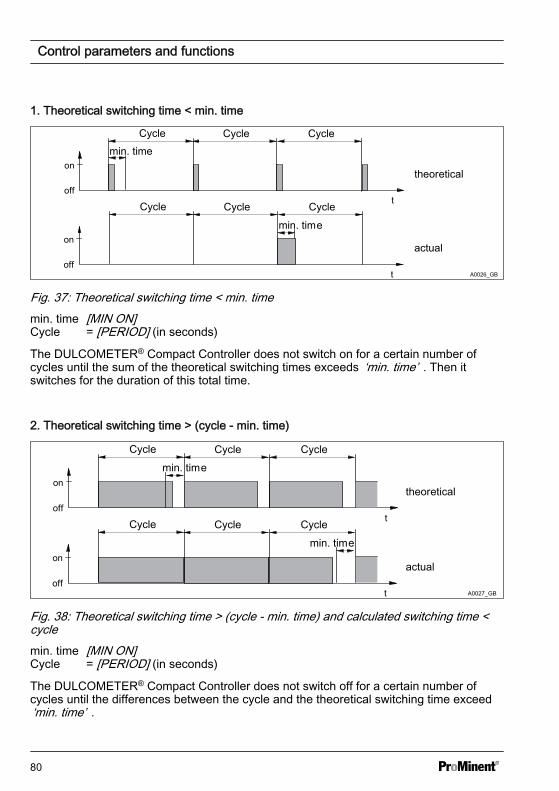
1. Theoretical switching time < min. time
off
on
t
off
on
t
Cycle Cycle Cycle
Cycle Cycle Cycle
min. time
min. time
theoretical
actual
A0026_GB
Fig. 37: Theoretical switching time < min. timemin. time [MIN ON]Cycle = [PERIOD] (in seconds)
The DULCOMETER® Compact Controller does not switch on for a certain number ofcycles until the sum of the theoretical switching times exceeds ‘min. time’ . Then itswitches for the duration of this total time.
2. Theoretical switching time > (cycle - min. time)
Cycle
min. time
off
on
t
off
on
t
Cycle Cycle
Cycle Cycle Cycle
min. time
theoretical
actual
A0027_GB
Fig. 38: Theoretical switching time > (cycle - min. time) and calculated switching time <cyclemin. time [MIN ON]Cycle = [PERIOD] (in seconds)
The DULCOMETER® Compact Controller does not switch off for a certain number ofcycles until the differences between the cycle and the theoretical switching time exceed‘min. time’ .
Control parameters and functions
80
9.10 Alarm relayThe alarm relay triggers in ‘OPERATION’(normal mode) if an error occurs whichhas been defined as ‘ERROR’ and notjust as ‘WARNING’ .The error message ‘ALARM’ in the con‐tinuous display is marked with a (star)and can be acknowledged with the key.The alarm and the will then disappear.
9.11 "Error logger" operatingmode
The last three errors are displayed. Alsodisplayed is how long ago (in minutes)they occurred. When a new fault occurs,the oldest fault is deleted.
Faults are only shown which occur inoperating status ‘OPERATION’ , i.e. not inoperating status ‘STOP’ , ‘CAL’ (user cali‐bration), ‘HOLD’ or ‘ PAUSE’ .Only ‘ERRORs’ are shown, not‘WARNINGS’ , e.g. a ‘LIMIT ERR’ isshown, but not ‘ LIMIT↑’ .A fault, whose display has lasted for 999minutes is automatically deleted from the‘Error Logger’ . The ‘Error Logger’ is nei‐ther saved nor backed up in the event ofpower loss.
Control parameters and functions
81
10 Maintenancen Users' qualification: trained user, see
Ä Chapter 2.2 ‘Users' qualifications’on page 10
The DULCOMETER® Compact Controlleris maintenance free.
10.1 Changing the fuse,DULCOMETER® Com‐pact Controller
WARNING!
Danger from electrical voltagePossible consequence: Fatal or veryserious injuries.
– The DULCOMETER® CompactController does not have a mainsswitch
– When working inside the controlunit, disconnect the control unitfrom the mains power via anexternal switch or by removingthe external fuse
NOTICE!
Use only 5 x 20 mm micro-fusesPossible consequence: Damage tothe product or its surroundings
– 5x20 T 0.315 A– Part number 732404
Fuse change
The mains fuse is located in a sealed fuseholder in the inside of the device.
1. Disconnect the controller from themains power
2. Open the controller and fold thecontroller housing top section to theleft
3. Remove the PCB cover
4. Remove the micro-fuse using asuitable tool
5. Fit the micro-fuse using a suitabletool
6. Refit the PCB cover
7. Replace controller housing top sec‐tion and close the controller
Maintenance
82
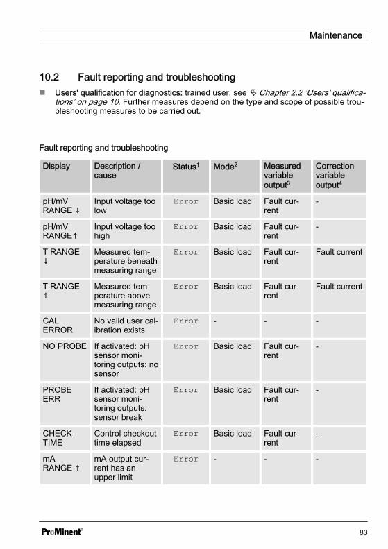
10.2 Fault reporting and troubleshootingn Users' qualification for diagnostics: trained user, see Ä Chapter 2.2 ‘Users' qualifica‐
tions’ on page 10. Further measures depend on the type and scope of possible trou‐bleshooting measures to be carried out.
Fault reporting and troubleshooting
Display Description /cause
Status1 Mode2 Measuredvariableoutput3
Correctionvariableoutput4
pH/mVRANGE ↓
Input voltage toolow
Error Basic load Fault cur‐rent
-
pH/mVRANGE↑
Input voltage toohigh
Error Basic load Fault cur‐rent
-
T RANGE↓
Measured tem‐perature beneathmeasuring range
Error Basic load Fault cur‐rent
Fault current
T RANGE↑
Measured tem‐perature abovemeasuring range
Error Basic load Fault cur‐rent
Fault current
CALERROR
No valid user cal‐ibration exists
Error - - -
NO PROBE If activated: pHsensor moni‐toring outputs: nosensor
Error Basic load Fault cur‐rent
-
PROBEERR
If activated: pHsensor moni‐toring outputs:sensor break
Error Basic load Fault cur‐rent
-
CHECK‐TIME
Control checkouttime elapsed
Error Basic load Fault cur‐rent
-
mARANGE ↑
mA output cur‐rent has anupper limit
Error - - -
Maintenance
83
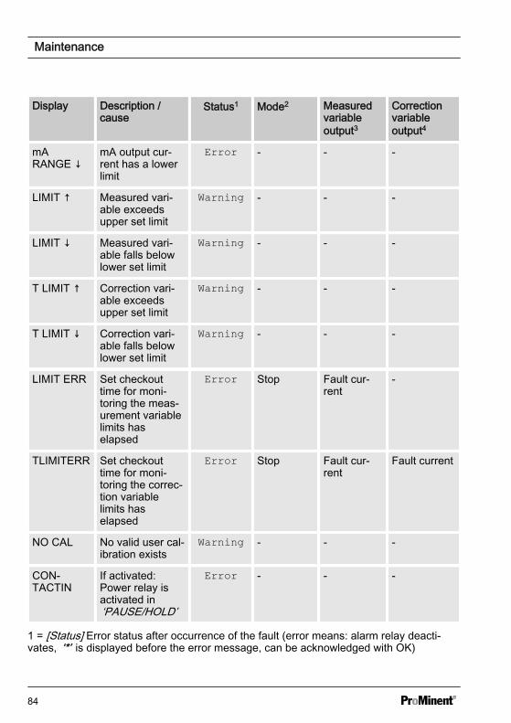
Display Description /cause
Status1 Mode2 Measuredvariableoutput3
Correctionvariableoutput4
mARANGE ↓
mA output cur‐rent has a lowerlimit
Error - - -
LIMIT ↑ Measured vari‐able exceedsupper set limit
Warning - - -
LIMIT ↓ Measured vari‐able falls belowlower set limit
Warning - - -
T LIMIT ↑ Correction vari‐able exceedsupper set limit
Warning - - -
T LIMIT ↓ Correction vari‐able falls belowlower set limit
Warning - - -
LIMIT ERR Set checkouttime for moni‐toring the meas‐urement variablelimits haselapsed
Error Stop Fault cur‐rent
-
TLIMITERR Set checkouttime for moni‐toring the correc‐tion variablelimits haselapsed
Error Stop Fault cur‐rent
Fault current
NO CAL No valid user cal‐ibration exists
Warning - - -
CON‐TACTIN
If activated:Power relay isactivated in‘PAUSE/HOLD’
Error - - -
1 = [Status] Error status after occurrence of the fault (error means: alarm relay deacti‐vates, ‘*’ is displayed before the error message, can be acknowledged with OK)
Maintenance
84
2 = [Mode] Resulting controller mode (relates to control variable and thus, as necessary,mA output)
3 = [Measured variable output] Consequence for the current output, if this is set as ‘ameasured variable output’4 = [Correction variable output] Consequence for the current output, if this is set as ‘acorrection variable output’
Maintenance
85
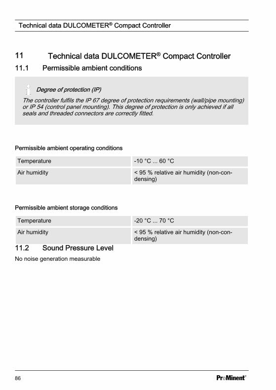
11 Technical data DULCOMETER® Compact Controller11.1 Permissible ambient conditions
Degree of protection (IP)The controller fulfils the IP 67 degree of protection requirements (wall/pipe mounting)or IP 54 (control panel mounting). This degree of protection is only achieved if allseals and threaded connectors are correctly fitted.
Permissible ambient operating conditions
Temperature -10 °C ... 60 °C
Air humidity < 95 % relative air humidity (non-con‐densing)
Permissible ambient storage conditions
Temperature -20 °C ... 70 °C
Air humidity < 95 % relative air humidity (non-con‐densing)
11.2 Sound Pressure LevelNo noise generation measurable
Technical data DULCOMETER® Compact Controller
86
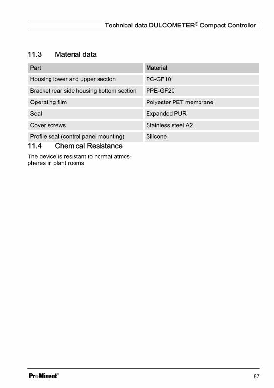
11.3 Material data
Part Material
Housing lower and upper section PC-GF10
Bracket rear side housing bottom section PPE-GF20
Operating film Polyester PET membrane
Seal Expanded PUR
Cover screws Stainless steel A2
Profile seal (control panel mounting) Silicone11.4 Chemical ResistanceThe device is resistant to normal atmos‐pheres in plant rooms
Technical data DULCOMETER® Compact Controller
87
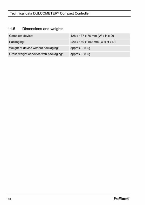
11.5 Dimensions and weights
Complete device: 128 x 137 x 76 mm (W x H x D)
Packaging: 220 x 180 x 100 mm (W x H x D)
Weight of device without packaging: approx. 0.5 kg
Gross weight of device with packaging: approx. 0.8 kg
Technical data DULCOMETER® Compact Controller
88
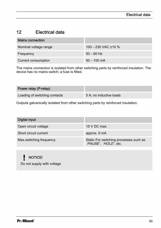
12 Electrical dataMains connection
Nominal voltage range 100 – 230 VAC ±10 %
Frequency 50 – 60 Hz
Current consumption 50 – 100 mA
The mains connection is isolated from other switching parts by reinforced insulation. Thedevice has no mains switch; a fuse is fitted.
Power relay (P-relay)
Loading of switching contacts 5 A; no inductive loads
Outputs galvanically isolated from other switching parts by reinforced insulation.
Digital input
Open circuit voltage 15 V DC max.
Short circuit current approx. 6 mA
Max.switching frequency Static For switching processes such as‘PAUSE’ , ‘HOLD’ , etc.
NOTICE!
Do not supply with voltage
Electrical data
89
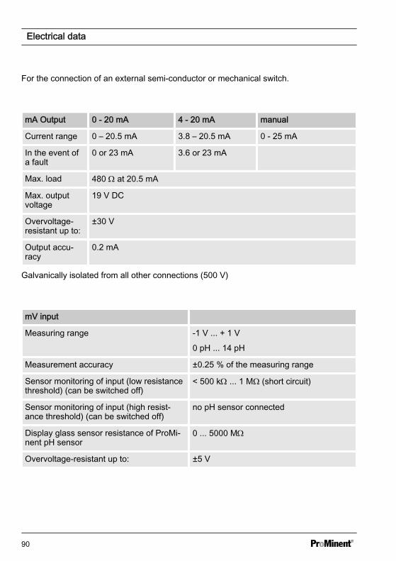
For the connection of an external semi-conductor or mechanical switch.
mA Output 0 - 20 mA 4 - 20 mA manual
Current range 0 – 20.5 mA 3.8 – 20.5 mA 0 - 25 mA
In the event ofa fault
0 or 23 mA 3.6 or 23 mA
Max. load 480 W at 20.5 mA
Max. outputvoltage
19 V DC
Overvoltage-resistant up to:
±30 V
Output accu‐racy
0.2 mA
Galvanically isolated from all other connections (500 V)
mV input
Measuring range -1 V ... + 1 V
0 pH ... 14 pH
Measurement accuracy ±0.25 % of the measuring range
Sensor monitoring of input (low resistancethreshold) (can be switched off)
< 500 kW ... 1 MΩ (short circuit)
Sensor monitoring of input (high resist‐ance threshold) (can be switched off)
no pH sensor connected
Display glass sensor resistance of ProMi‐nent pH sensor
0 ... 5000 MW
Overvoltage-resistant up to: ±5 V
Electrical data
90
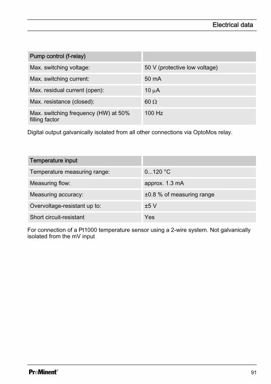
Pump control (f-relay)
Max. switching voltage: 50 V (protective low voltage)
Max. switching current: 50 mA
Max. residual current (open): 10 mA
Max. resistance (closed): 60 W
Max. switching frequency (HW) at 50%filling factor
100 Hz
Digital output galvanically isolated from all other connections via OptoMos relay.
Temperature input
Temperature measuring range: 0...120 °C
Measuring flow: approx. 1.3 mA
Measuring accuracy: ±0.8 % of measuring range
Overvoltage-resistant up to: ±5 V
Short circuit-resistant Yes
For connection of a Pt1000 temperature sensor using a 2-wire system. Not galvanicallyisolated from the mV input
Electrical data
91
13 Spare parts and accessoriesSpare parts Part number
Fine fuse 5x20 T 0.315 A 732404
Wall/tube retaining bracket 1002502
Guard terminal top part (knurled nut) 733389
Measured variable labels 1002503
DMT fixing strap 1002498
Cable connection set DMTa/DXMa (metric) 1022312
Controller housing lower part (processor/PCB), fullyassembled
Identity codeDCCA_E_E1 ...
Controller housing top part (display/operating part), fullyassembled
Identity codeDCCA_E_E2 ...
Accessories Part number
Mounting kit for control panel installation 1037273
Check strap 1035918
Spare parts and accessories
92
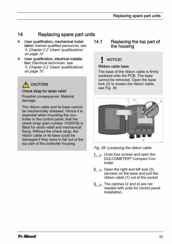
14 Replacing spare part unitsn User qualification, mechanical instal‐
lation: trained qualified personnel, seeÄ Chapter 2.2 ‘Users' qualifications’on page 10
n User qualification, electrical installa‐tion: Electrical technician, seeÄ Chapter 2.2 ‘Users' qualifications’on page 10
CAUTION!
Check strap for strain reliefPossible consequence: Materialdamage.
The ribbon cable and its base cannotbe mechanically stressed. Hence it isessential when mounting the con‐troller in the control panel, that thecheck strap (part number 1035918) isfitted for strain relief and mechanicalfixing. Without the check strap, theribbon cable or its base could bedamaged if they were to fall out of thetop part of the controller housing.
14.1 Replacing the top part ofthe housing
NOTICE!
Ribbon cable baseThe base of the ribbon cable is firmlysoldered onto the PCB. The basecannot be removed. Open the baselock (3) to loosen the ribbon cable,see Fig. 39
1. 2. 3.
4.
Fig. 39: Loosening the ribbon cable1. Undo four screws and open the
DULCOMETER® Compact Con‐troller
2. Open the right and left lock (3)(arrows) on the base and pull theribbon cable (1) out of the socket
3. The catches (2 and 4) are notneeded with units for control panelinstallation.
Replacing spare part units
93
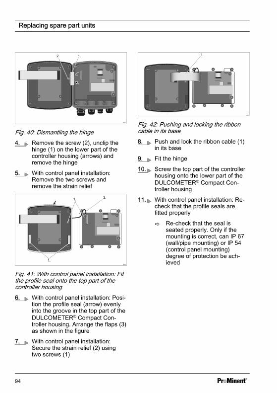
1.2.
Fig. 40: Dismantling the hinge4. Remove the screw (2), unclip the
hinge (1) on the lower part of thecontroller housing (arrows) andremove the hinge
5. With control panel installation:Remove the two screws andremove the strain relief
A0351
1.
2.1.
Fig. 41: With control panel installation: Fitthe profile seal onto the top part of thecontroller housing6. With control panel installation: Posi‐
tion the profile seal (arrow) evenlyinto the groove in the top part of theDULCOMETER® Compact Con‐troller housing. Arrange the flaps (3)as shown in the figure
7. With control panel installation:Secure the strain relief (2) usingtwo screws (1)
A0352
1.
Fig. 42: Pushing and locking the ribboncable in its base8. Push and lock the ribbon cable (1)
in its base
9. Fit the hinge
10. Screw the top part of the controllerhousing onto the lower part of theDULCOMETER® Compact Con‐troller housing
11. With control panel installation: Re-check that the profile seals arefitted properly
ð Re-check that the seal isseated properly. Only if themounting is correct, can IP 67(wall/pipe mounting) or IP 54(control panel mounting)degree of protection be ach‐ieved
Replacing spare part units
94
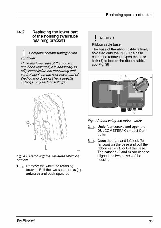
14.2 Replacing the lower partof the housing (wall/tuberetaining bracket)
Complete commissioning of thecontrollerOnce the lower part of the housinghas been replaced, it is necessary tofully commission the measuring andcontrol point, as the new lower part ofthe housing does not have specificsettings, only factory settings.
2
1
A0273
Fig. 43: Removing the wall/tube retainingbracket1. Remove the wall/tube retaining
bracket. Pull the two snap-hooks (1)outwards and push upwards
NOTICE!
Ribbon cable baseThe base of the ribbon cable is firmlysoldered onto the PCB. The basecannot be removed. Open the baselock (3) to loosen the ribbon cable,see Fig. 39
1. 2. 3.
4.
Fig. 44: Loosening the ribbon cable2. Undo four screws and open the
DULCOMETER® Compact Con‐troller
3. Open the right and left lock (3)(arrows) on the base and pull theribbon cable (1) out of the base.The catches (2 and 4) are used toaligned the two halves of thehousing.
Replacing spare part units
95
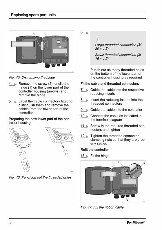
1.2.
Fig. 45: Dismantling the hinge4. Remove the screw (2), unclip the
hinge (1) on the lower part of thecontroller housing (arrows) andremove the hinge
5. Label the cable connectors fitted todistinguish them and remove thecables from the lower part of thecontroller
Preparing the new lower part of the con‐troller housing
A0272
Fig. 46: Punching out the threaded holes
6.
Large threaded connection (M20 x 1.5)Small threaded connection (M16 x 1.5)
Punch out as many threaded holeson the bottom of the lower part ofthe controller housing as required
Fit the cable and threaded connectors
7. Guide the cable into the respectivereducing inserts
8. Insert the reducing inserts into thethreaded connectors
9. Guide the cable into the controller
10. Connect the cable as indicated inthe terminal diagram
11. Screw in the required threaded con‐nectors and tighten
12. Tighten the threaded connectorclamping nuts so that they are prop‐erly sealed
Refit the controller
13. Fit the hinge
1. 2. 3.
4.
Fig. 47: Fix the ribbon cable
Replacing spare part units
96
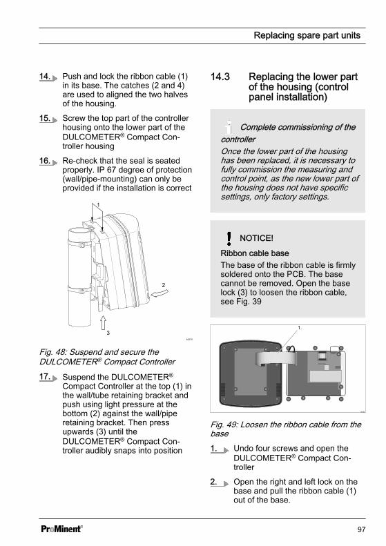
14. Push and lock the ribbon cable (1)in its base. The catches (2 and 4)are used to aligned the two halvesof the housing.
15. Screw the top part of the controllerhousing onto the lower part of theDULCOMETER® Compact Con‐troller housing
16. Re-check that the seal is seatedproperly. IP 67 degree of protection(wall/pipe-mounting) can only beprovided if the installation is correct
A0275
3
2
1
Fig. 48: Suspend and secure theDULCOMETER® Compact Controller17. Suspend the DULCOMETER®
Compact Controller at the top (1) inthe wall/tube retaining bracket andpush using light pressure at thebottom (2) against the wall/piperetaining bracket. Then pressupwards (3) until theDULCOMETER® Compact Con‐troller audibly snaps into position
14.3 Replacing the lower partof the housing (controlpanel installation)
Complete commissioning of thecontrollerOnce the lower part of the housinghas been replaced, it is necessary tofully commission the measuring andcontrol point, as the new lower part ofthe housing does not have specificsettings, only factory settings.
NOTICE!
Ribbon cable baseThe base of the ribbon cable is firmlysoldered onto the PCB. The basecannot be removed. Open the baselock (3) to loosen the ribbon cable,see Fig. 39
A0352
1.
Fig. 49: Loosen the ribbon cable from thebase1. Undo four screws and open the
DULCOMETER® Compact Con‐troller
2. Open the right and left lock on thebase and pull the ribbon cable (1)out of the base.
Replacing spare part units
97
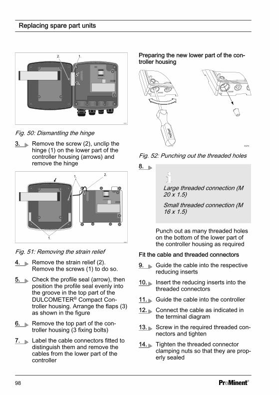
1.2.
Fig. 50: Dismantling the hinge3. Remove the screw (2), unclip the
hinge (1) on the lower part of thecontroller housing (arrows) andremove the hinge
A0351
1.
2.1.
Fig. 51: Removing the strain relief4. Remove the strain relief (2).
Remove the screws (1) to do so.
5. Check the profile seal (arrow), thenposition the profile seal evenly intothe groove in the top part of theDULCOMETER® Compact Con‐troller housing. Arrange the flaps (3)as shown in the figure
6. Remove the top part of the con‐troller housing (3 fixing bolts)
7. Label the cable connectors fitted todistinguish them and remove thecables from the lower part of thecontroller
Preparing the new lower part of the con‐troller housing
A0272
Fig. 52: Punching out the threaded holes8.
Large threaded connection (M20 x 1.5)Small threaded connection (M16 x 1.5)
Punch out as many threaded holeson the bottom of the lower part ofthe controller housing as required
Fit the cable and threaded connectors
9. Guide the cable into the respectivereducing inserts
10. Insert the reducing inserts into thethreaded connectors
11. Guide the cable into the controller
12. Connect the cable as indicated inthe terminal diagram
13. Screw in the required threaded con‐nectors and tighten
14. Tighten the threaded connectorclamping nuts so that they are prop‐erly sealed
Replacing spare part units
98
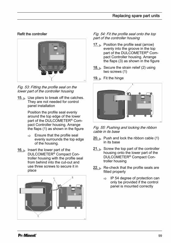
Refit the controller
A03601.
Fig. 53: Fitting the profile seal on thelower part of the controller housing15. Use pliers to break off the catches.
They are not needed for controlpanel installation
Position the profile seal evenlyaround the top edge of the lowerpart of the DULCOMETER® Com‐pact Controller housing. Arrangethe flaps (1) as shown in the figure
ð Ensure that the profile sealevenly surrounds the top edgeof the housing.
16. Insert the lower part of theDULCOMETER® Compact Con‐troller housing with the profile sealfrom behind into the cut-out anduse three screws to secure it inplace
A0351
1.
2.1.
Fig. 54: Fit the profile seal onto the toppart of the controller housing17. Position the profile seal (arrow)
evenly into the groove in the toppart of the DULCOMETER® Com‐pact Controller housing. Arrangethe flaps (3) as shown in the figure
18. Secure the strain relief (2) usingtwo screws (1)
19. Fit the hinge
A0352
1.
Fig. 55: Pushing and locking the ribboncable in its base20. Push and lock the ribbon cable (1)
in its base
21. Screw the top part of the controllerhousing onto the lower part of theDULCOMETER® Compact Con‐troller housing
22. Re-check that the profile seals arefitted properly
ð IP 54 degree of protection canonly be provided if the controlpanel is mounted correctly
Replacing spare part units
99

15 Standards complied with and Declaration of ConformityThe EC Declaration of Conformity for thecontroller is available to download on ourhomepage.
EN 60529 Specification for degrees ofprotection provided by housings (IP code)
EN 61000 Electromagnetic Compatibility(EMC)
EN 61010 Safety requirements for elec‐trical equipment for measurement, controland laboratory use - Part 1: Generalrequirements
EN 61326 Electrical equipment for meas‐uring, control and laboratory use - EMCrequirements (for class A and B devices)
Standards complied with and Declaration of Conformity
100
16 Disposal of Used Partsn User qualification: instructed user,
see Ä Chapter 2.2 ‘Users' qualifica‐tions’ on page 10
NOTICE!
Regulations governing the disposal ofused parts– Note the current national regula‐
tions and legal standards whichapply in your country
The manufacturer will take back decon‐taminated used units providing they arecovered by adequate postage.
Decontaminate the unit before returning itfor repair. To do so, remove all traces ofhazardous substances. Refer to the Mate‐rial Safety Data Sheet for your feed chem‐ical.
A current Declaration of Decontaminationis available to download on the ProMinentwebsite.
Disposal of Used Parts
101
17 Index1, 2, 3 ...1-Point slope calibration . . . . . . . . . . 532-Point Calibration . . . . . . . . . . . . . . 50
AAccess . . . . . . . . . . . . . . . . . . . . . . 19Accessibility . . . . . . . . . . . . . . . . . . . 20Accessories . . . . . . . . . . . . . . . . . . . 92Action, step by step . . . . . . . . . . . . . . 2Ambient conditions . . . . . . . . . . . . . . 86
BBasic functions . . . . . . . . . . . . . . . . 15Bottom section of the control housing . 28
CCable connection set . . . . . . . . . . . . 22Cable ties . . . . . . . . . . . . . . . . . . . . 24Calibration . . . . . . . . . . . . . . . . . . . . 50Check strap . . . . . . . . . . . . . . . . . . . 92Check strap for strain relief . . . . . . . . 93Chemical Resistance . . . . . . . . . . . . 87Coaxial cable 10 m . . . . . . . . . . . . . . 34Configuration . . . . . . . . . . . . . . . . . . 15Contrast setting . . . . . . . . . . . . . . . . 44Control elements . . . . . . . . . . . . . . . 43Control panel cut-out . . . . . . . . . . 26, 28
DDeburr the edges . . . . . . . . . . . . . . . 26Declaration of Conformity . . . . . . . . 100Degree of protection IP 54 . . . . . . 28, 39Degree of protection IP 67 . . . . . . 20, 39Dimensions . . . . . . . . . . . . . . . . . . . 88Drill . . . . . . . . . . . . . . . . . . . . . . . . 26Drill holes . . . . . . . . . . . . . . . . . . . . 23Drilling template . . . . . . . . . . . . . . . . 26
EError Logger . . . . . . . . . . . . . . . . . . 81
FFine fuse 5x20 T 0.315 A . . . . . . . . . 92
GGeneral non-discriminatory approach . . 2Guard terminal XE 1 . . . . . . . . . . . . . 34
HHinge . . . . . . . . . . . . . . . . . . . . . . . 20Hysteresis . . . . . . . . . . . . . . . . . . . . 59
IIdentity code . . . . . . . . . . . . . . . . . . . 6Incorrect metering . . . . . . . . . . . . . . 41Interference-prone cables . . . . . . . . . 33
LLarge threaded connection (M 20 x1.5) . . . . . . . . . . . . . . . . . . . . . . . . 39LEDs . . . . . . . . . . . . . . . . . . . . . . . 15Legend to the "Wiring" table . . . . . . . . 37Links to elements or sections of theseinstructions or other applicable docu‐ments . . . . . . . . . . . . . . . . . . . . . . . . 2
MMaterial thickness of control panel . . . 25Max. switching current: . . . . . . . . . . 91Max. switching voltage: . . . . . . . . . . . 91Measured variables . . . . . . . . . . . . . 15More symbols . . . . . . . . . . . . . . . . . . 2Mounting (mechanical) . . . . . . . . . . . 22Mounting kit . . . . . . . . . . . . . . . . . . . 25Mounting materials . . . . . . . . . . . . . . 22Mounting position . . . . . . . . . . . . . . . 21
NNoise generation . . . . . . . . . . . . . . . 86Non-discriminatory approach . . . . . . . . 2
OOperating position . . . . . . . . . . . . . . 21
Index
102
Original Prominent cable . . . . . . . . . . 37Overview of equipment . . . . . . . . . . 43
PPipe bracket . . . . . . . . . . . . . . . . . . 23Pipe diameter . . . . . . . . . . . . . . . . . 24plant rooms . . . . . . . . . . . . . . . . . . . 87Preparing the control panel . . . . . . . . 26Profile seal . . . . . . . . . . . . . . . . . . . 28Punch out threaded holes . . . . . . . . . 39PWM control output . . . . . . . . . . . . . 15
QQuestion: Are the ribbon cable or itsattaching parts mechanically load‐able? . . . . . . . . . . . . . . . . . . . . . . . 20Question: What degree of protection(IP) does the device meet? . . . . . . . . 20Question: What is the purpose of thecheck strap (part number 1035918)? . 20Question: Where can I find the Decla‐ration of Conformity? . . . . . . . . . . . . 100Question: Which standards are com‐plied with? . . . . . . . . . . . . . . . . . . . 100
RReading position . . . . . . . . . . . . . . . 21Recycling . . . . . . . . . . . . . . . . . . . . 21Reducing inserts . . . . . . . . . . . . . . . 39Replacing spare part units . . . . . . . . . 93Replacing the lower part of thehousing (control panel installation) . . . 97Replacing the lower part of thehousing (wall/tube retaining bracket) . . 95Replacing the top part of the housing . 93Reset . . . . . . . . . . . . . . . . . . . . . . . 41
SSafety information . . . . . . . . . . . . . . . 8Selectable control direction . . . . . . . . 15Sensor monitoring . . . . . . . . . . . . . . 91Single point zero point calibration . . . . 55Small threaded connection (M 16 x1.5) . . . . . . . . . . . . . . . . . . . . . . . . 39Snap-hooks . . . . . . . . . . . . . . . . . . . 23Sound Pressure Level . . . . . . . . . . . . 86Spare parts . . . . . . . . . . . . . . . . . . . 92Standard scope of delivery . . . . . . . . 22Standards complied with . . . . . . . . . 100Strain relief . . . . . . . . . . . . . . . . 28, 39Swimming pool water treatment . . . . . 15
TTemperature compensation . . . . . 15, 76Terminal diagram . . . . . . . . . . . . . . . 38Threaded connector number . . . . . . . 35Top section of the control housing . . . 28Treatment of drinking water . . . . . . . . 15
UUsers' qualifications . . . . . . . . . . . . . 10
VVenting . . . . . . . . . . . . . . . . . . . . . . 74
WWall/pipe bracket . . . . . . . . . . . . . . . 23Washer . . . . . . . . . . . . . . . . . . . . . . 22Waste water treatment . . . . . . . . . . . 15Weights . . . . . . . . . . . . . . . . . . . . . 88Wiring . . . . . . . . . . . . . . . . . . . . . . . 37
Index
103
986214, 4, en_GB
© 2015
ProMinent GmbHIm Schuhmachergewann 5 - 1169123 Heidelberg, GermanyTelephone: +49 6221 842-0Fax: +49 6221 842-419Email: [email protected]: www.prominent.com