Embed Size (px)
Citation preview
Development of Nanoparticle Sensitized
Solar Cells
Chunze Yuan
元春泽
Doctoral Thesis in Theoretical Chemistry & Biology
School of Biotechnology
Royal Institute of Technology
Stockholm, Sweden 2013

Development of Nanoparticle Sensitized Solar Cells
Thesis for Philosophy Doctor Degree
Department of Theoretical Chemistry & Biology
School of Biotechnology
Royal Institute of Technology
© Chunze Yuan, 2013
ISBN 978-91-7501-862-1
ISSN 1654-2312
TRITA-BIO Report 2013:16

To my family!

Abstract
In this thesis, I have been working with the development of nanoparticle
sensitized solar cells. In the subarea of quantum dot sensitized solar cells
(QDSCs), I have investigated type-II quantum dots (QDs), quantum rods
(QRs) and alloy QDs, and developed novel redox couples as electrolytes. I
have also proposed upconversion nanoparticles as energy relay materials for
dye-sensitized solar cells (DSCs).
Colloidal ZnSe/CdS type-II QDs were applied for QDSCs for the first time.
The interesting features of those refer to that their photoelectrons and
photoholes are located on the different parts of the dot, namely in the CdS
shell and in the ZnSe core, respectively. That spatial separation between
photoelectrons and photoholes can so effectively enhance the charge
extraction efficiency, thus facilitating the electron injection, and also
effectively expand the absorption spectrum. All these characteristics
contribute to a high photon to current conversion efficiency. Furthermore, a
comparison between the photovoltaic performance of ZnSe/CdS and
CdS/ZnSe QDSCs shows that the electron distribution is important for the
electron injection of the QDs.
Colloidal CdS/CdSe QRs were applied to quantum rod-sensitized solar cells
(QRSCs). They showed a higher electron injection efficiency than the
analogous QDSCs. It is concluded that reduction of the carrier confinement
dimensions of the nanoparticles can improve the electron injection efficiency
of the nanoparticle sensitized solar cells.
Two types of organic electrolytes based on the redox couples of McMT-
/BMT (OS1) and TMTU/TMTU-TFO (OS2) were used for the QDSCs. By
reducing the charge recombination between the electrolyte and the counter
electrode, the fill factor and the photovoltage of these QDSCs were
significantly improved, resulting in a higher efficiency for the studied solar
cells than that with a commonly used inorganic electrolyte.
Ternary-alloy PbxCd1-xS QDs used as photosensitizers for QDSCs were
found to improve the photocurrent compared to the corresponding CdS and
PbS QDs. By considering the effect of different ratios of Pb to Cd in the
PbxCd1-xS QDs on the photovoltaic performance it was discovered that the
photocurrent increases and the photovoltage decreases with the increase of the
ratio in a certain range.
Upconversion (UC) nanoparticles provide a strategy to develop
panchromatic solar cells. Three types of UC nanoparticles employed by DSCs
were confirmed to work as energy relay materials for effectively extending
the light-harvesting spectrum to the near-infrared (NIR) region. They were
also found to play a role as scattering centers to enhance the photovoltaic
performance of the solar cells.
Keywords: quantum dots, quantum rods, nanoparticles, solar cells, colloidal,
type-II, electron extraction, alloy, organic electrolyte, energy relay,
upconversion.
Abbreviations
QDs Quantum dots
QRs Quantum rods
NPs Nanoparticles
QY Quantum yield
PL Photoluminescence
SSCs Sensitized solar cells
DSCs Dye-sensitized solar cells
QDSCs Quantum dots-sensitized solar cells
QRSCs Quantum rods-sensitized solar cells
McMT-/BMT A type of organic redox couple for electrolyte
TMTU/TMTU-TFO A type of organic redox couple for electrolyte
Jsc Short-circuit current density
Voc Open-circuit voltage
FF Fill factor
η The overall efficiency of a solar cell
IPCE Incident photon to current conversion efficiency
APCE Absorbed photon to current conversion efficiency
UV-Vis Ultraviolet-visible
J-V Current density-voltage
λ Wavelength of light
Eg Bandgap
HOMO Highest occupied molecular orbital
LUMO Lowest unoccupied molecular orbital
TEM Transmission electron microscopy
SEM Scanning electron microscopy
CB Conduction band
VB Valence band
AM Air Mass
TiO2 Titanium dioxide
NHE Normal hydrogen electrode
ODE Octadecene
TOP Trioctylphosphine
OA Oleic acid
ODA 1-octadecanamine
FTO Fluoride-doped tin oxide
MPA Mercaptopropionic acid
CBD Chemical bath deposition
SILAR Successive ion layer adsorption reactions
UC Upconversion
UCP Upconversion particles
NIR Near-infrared
HTM Hole transport material

List of Publications
This thesis is based on the following papers, referred to in the text by their
Roman numerals I-VII:
I. Use of colloidal upconversion nanocrystals for energy relay solar
cell light harvesting in the near-infrared region
Chunze Yuan, Guanying Chen, Paras N. Prasad, Tymish Y.
Ohulchanskyy, Zhijun Ning, Haining Tian, Licheng Sun and Hans
Ågren
J. Mater. Chem., 2012, 22, 16709–16713.
II. Effective dual-NIR-wavelength energy relay of colloidal
upconversion nanoparticles for dye-sensitized solar cells
Chunze Yuan, Guanying Chen, Lin Li, Jossana Damasco, Zhijun
Ning , Hui Xing, Tianmu Zhang, Licheng Sun, Hao Zeng, Paras N.
Prasad and Hans Ågren.
Manuscript
III. A strategy to improve photocurrent of quantum dot sensitized solar
cells by employing alloy PbxCd1-xS QDs as photosensitizers
Chunze Yuan, Lin Li, Zhijun Ning, Jing Huang, Licheng Sun and Hans
Ågren.
Manuscript
IV. Solar cells sensitized with type-II ZnSe-CdS core/shell colloidal
quantum dots
Zhijun Ning, Haining Tian, Chunze Yuan, Ying Fu, Haiyan Qin,
Licheng Sun and Hans Ågren
Chem. Commun., 2011, 47, 1536-1538.
V. Quantum rod sensitized solar cells
Zhijun Ning, Chunze Yuan, Haining Tian, Peter Hedström, Licheng
Sun and Hans Ågren
ChemSusChem, 2011, 4, 1741-1744.
VI. Type-II colloidal quantum dot sensitized solar cells with a thiourea
based organic redox couple
Zhijun Ning, Chunze Yuan, Haining Tian, Ying Fu, Lin Li, Licheng
Sun and Hans Ågren
J. Mater. Chem., 2012, 22, 6032-6037.
VII. Pure organic redox couple for quantum dot sensitized solar cells
Zhijun Ning, Haining Tian, Chunze Yuan, Ying Fu, Licheng Sun and
Hans Ågren
Chem. Eur. J., 2011, 17, 6330 -6333.
Contribution to the Publications
I made the major contributions in the fabrication of solar cells, measurements,
discussion, analysis and writing for Papers I and II.
I made the major contributions to the synthesis, measurements, discussion,
analysis and writing for Paper III.
I took part of the work on the synthesis, measurements, discussion, analysis
and writing for Papers V and VI.
I took part of the work on the synthesis, measurements, discussion, analysis
for Papers IV and VII.

Table of Contents
Abstract
Abbreviations
List of Publications
Contribution to the Publications
1. Introduction and Aim of Thesis ............................................................................... - 1 -
2. Overview of Solar Energy ........................................................................................ - 5 -
2.1 Energy crisis and renewable energy resources ................................................. - 5 -
2.2 Solar energy and solar constant ........................................................................ - 6 -
2.3 Utilization of solar energy and development of solar cells .............................. - 8 -
3. Semiconductor and Upconversion Nanoparticles ................................................ - 11 -
3.1 Semiconductor Nanoparticles ........................................................................ - 11 -
3.1.1 Classification of QDs .............................................................................. - 12 -
3.1.2 Characteristics of QDs ............................................................................ - 14 -
3.1.2.1. Size-dependent effect .......................................................................... - 14 -
3.1.2.2. Multiple exciton generation ................................................................ - 16 -
3.1.3 Type-I and type-II core/shell QDs .......................................................... - 17 -
3.1.4 Quantum rods .......................................................................................... - 19 -
3.2 Upconversion nanoparticles ........................................................................... - 20 -
4. Sensitized Solar Cells .............................................................................................. - 23 -
4.1 Development of sensitized solar cells ............................................................ - 23 -
4.1.1 Quantum dot sensitized solar cells .......................................................... - 23 -
4.1.2 DSCs with upconversion materials for energy relay .............................. - 25 -
4.2 Working principle and basic components of SSCs ........................................ - 26 -
4.2.1 Working principle ................................................................................... - 26 -
4.2.1.1. QDSCs ................................................................................................. - 26 -
4.2.1.2. UC-particle-based DSCs ..................................................................... - 28 -
4.2.2 Basic components ................................................................................... - 30 -
4.2.2.1. Mesoporous nanocrystalline semiconductors...................................... - 30 -
4.2.2.2. QD sensitizers ..................................................................................... - 31 -
4.2.2.3. Electrolyte ........................................................................................... - 32 -
4.2.2.4. Counter electrode ................................................................................ - 32 -

4.3 Synthesis of colloidal nanoparticles ............................................................... - 33 -
4.3.1 Synthesis of colloidal QDs...................................................................... - 33 -
4.3.2 Synthesis of QRs ..................................................................................... - 35 -
4.3.3 Synthesis of colloidal UC nanoparticles ................................................. - 36 -
4.4 Fabrication and assembly of sensitized solar cells ......................................... - 36 -
4.4.1 Fabrication of TiO2 photoelectrode ........................................................ - 36 -
4.4.2 QD deposition onto photoelectrode ........................................................ - 37 -
4.4.2.1. In situ growth of QDs on photoelectrode ............................................ - 37 -
4.4.2.2. Deposition by a bifunctional linker molecule ..................................... - 38 -
4.4.3 Fabrication of counter electrode ............................................................. - 39 -
4.4.4 Assembly of sensitized solar cells .......................................................... - 39 -
4.5 Characterization ............................................................................................. - 40 -
4.5.1 Optical characterization .......................................................................... - 40 -
4.5.1.1. UV-Vis Absorption Spectroscopy ....................................................... - 40 -
4.5.1.2. Fluorescence spectroscopy .................................................................. - 40 -
4.5.2 Characterization of photovoltaic performance of solar cells .................. - 41 -
4.5.2.1. Photon to current conversion efficiency (IPCE and APCE) ............... - 41 -
4.5.2.2. Current density-voltage characteristics (J-V) ...................................... - 42 -
5. Results and Discussion ............................................................................................ - 45 -
5.1 Study of type-II QDs sensitized solar cells (Papers IV and VI)..................... - 45 -
5.2 Study of quantum rod-sensitized solar cells (Paper V) .................................. - 47 -
5.3 Study of alloy PbxCd1-xS QDSCs (Paper III) ................................................. - 49 -
5.4 Study of QDSCs based on pure organic electrolyte (Papers VI and VII) ...... - 51 -
5.5 Study of energy relay DSCs with UC nanoparticles (Papers I and II) ........... - 52 -
6. Conclusion and Future Outlook ............................................................................ - 59 -
Acknowledgements ..................................................................................................... - 62 -
References .................................................................................................................... - 64 -
- 1 -
Chapter 1
Introduction and Aim of Thesis
Following the extensive use of the traditional fossil energy sources, the
environmental pollution and the energy crisis have become major issues for
mankind. The development and the utilization of clean and renewable energy
sources have more and more developed to become an imminent issue.
Humans have been able to successfully use a variety of green energy sources,
for instance, tidal, geothermal, wind and solar energy. However, among
various energy resources, wind, geothermal and tidal energy have been
heavily limited to the popularization for civilians, while due to geographical
and other factors, they have not been applied on the large scales needed. Solar
energy as a new kind of renewable energy has the characteristics of no
pollution, basically no geographical restrictions, rich reserves, use of
diversification and so forth. If we can use solar energy effectively, all the
energy needed for the human activities can be provided by the Sun.
At present, the main method of utilization of solar energy is the conversion
of solar energy into other energy sources. In 1954 silicon solar cells were
developed by Bell, marking that humans can convert solar energy into
electrical energy for practical utilization for the first time.1 However, it is not
suitable for large-scale civilian use as this type of solar cell has a stringent
requirement for the raw materials and the production process. Although the
subsequent development of polysilicon and amorphous silicon solar cells is
relatively simple in the production process, the high prices still can’t meet
large-scale utilization.
In 1991, Professor Grätzel reported a novel kind of low-cost sensitized
solar cell (SSC) using organic dyes adsorbed on a nanocrystal titanium
dioxide (TiO2) film as the photoanode, that later became known as the Grätzel
cell or dye-sensitized solar cell (DSC).2 The first cell gave a photoelectric
conversion efficiency of 7% under simulated sunlight irradiation. After

- 2 -
development during twenty years, the efficiency of this kind of solar cell has
now become as high as 12%.3,4 Because of the simple production process,
much lower cost relative to silicon cells and a lifetime of more than 15 years,
this type of solar cells provide a feasible approach for large-scale utilization
of solar energy.5 Actually it is highly possible for the efficiency of DSCs to
further increase, for example by extending the light-harvesting into the NIR
region.
In the recent decades, quantum dots (QDs), also referred to as
semiconductor nanocrystals, have come at the research focus in many areas
of technical applications, like biomarkers,6,7 light-emitting diodes8 and
photovoltaic devices,9 due to their unique electronic and optical properties. In
particular, quantum dots-sensitized solar cells (QDSCs) are of great interest
because of their excellent performance of low-cost, photostability, high molar
extinction coefficients and size-dependent optical properties.10-13 Furthermore,
their special multi-electron generation character can enable the theoretically
maximum efficiency to be as high as 44%,14 much higher than that of dye
based DSCs. Although QDSCs have been developed very quickly, their
efficiency level is still lower than that of the DSCs.15, 16 This is mainly a result
from the high electron loss between electrolyte and electrodes (photoelectrode
and counter electrode) and the relatively narrow absorption spectra of most of
the efficient QDs. Thus, to increase the conversion efficiency, much effort has
been concentrated to develop properties of QDs referring to electron transport
rate, light harvesting ability, the catalytic ability of counter electrode and
decrease of charge recombination.
The aim of this thesis is to develop nanoparticle based sensitized solar cells.
One part deals with how to improve the photovoltaic performance of the
QDSCs by optimizing the size, structure and shape of the QDs, and using new
types electrolytes. Thus, this part of my thesis work was divided into two
projects: The first project focused on the chemical synthesis of the type-II
QDs and quantum rods (QRs) applied in QDSCs in order to enhance the
conversion efficiency via increasing the electron extraction efficiency and
electron injection efficiency. The second project was committed to try some
organic redox couples as the electrolyte of QDSCs. In addition, we also made
a study on QDSCs based on alloy QDs. Another important part in this thesis
- 3 -
is to develop energy relay DSCs employing colloidal upconversion (UC)
nanoparticles as the energy relay materials for effective utilization of energy
in the near-infrared (NIR) region.

- 4 -

- 5 -
Chapter 2
Overview of Solar Energy
2.1 Energy crisis and renewable energy resources
In the 21st century, society will face a major challenge to achieve
sustainably economic and social developments under the astringent
requirements of the limited resources and environmental protection. This has
become a global hot issue. The energy issue will become more prominent due
to not only the lack of conventional energy but also a series of adverse
consequences brought by the consumption of fossil fuels.
1. Energy shortage
With the limitation and uneven distribution of the conventional energy
sources, the energy supply of most countries can not meet the demands
of the economic development. Therefore, humans will face the
exhaustion of fossil fuel sooner or later, if they can not find alternative
energy.
2. Environmental pollution
Currently, due to the burning of fossil fuels, a huge amount of sulfur
and poisonous substances are emitted into the sky every day, bringing
pollution to the atmospheric environment, soil and water. Due to these
issues, mankind will eventually have to change the energy structure and
rely on the use of solar and other kinds of renewably clean energy
sources.
3. Greenhouse effect
The use of fossil fuels also causes the greenhouse effect due to large
amounts of CO2 emission, resulting in global climate alteration. Its
- 6 -
impact has been even more serious than the environmental pollution.
This problem has been referred to as the global agenda.
To solve the energy problem and achieve a sustainable development,
humans have to rely on scientific and technological processes to develop
large-scale utilization of renewable and clean energy. Renewable energy
refers to the renewable, sustainable and inexhaustible resources in nature,
which is (almost) harmless to the environment, widely distributable and
suitable for in situ exploitation and utilization. These mainly include solar,
wind, hydro, biomass, geothermal and tidal energy. Currently, renewable
energy is in a stage of rapid development and some technology is at or near
the level of commercialization. The wind power technology has become
relatively mature. From the 2011 report of the American Wind Energy
Association,17 wind power costs about 5~6 cents/kWh, making wind energy
to compete with nuclear power, coal and gas under the same conditions.
Although wind energy has the advantage of low cost and no pollution, there
are still limitations because of geography. Solar energy with its unique
characteristics and economic advantage will have a considerable development
on the exploitation and the utilization in the 21st century.
2.2 Solar energy and solar constant
Solar energy is generated by the continuous fusion reactions inside the Sun.
The total energy emitted from the Sun is about 3.75× 1026 W, one of 2.2 billion
of which can be obtained by the Earth. If the cells with 10% of photoelectric
conversion efficiency cover 0.1% of the Earth’s surface, the produced energy
can meet all human’s energy needs.18 The main characteristics of the
exploitation and the utilization of solar energy are as follows.
1. “Infinity” reserve
The solar energy reaching the Earth’s surface within one year is one
million times of the current proven reserves of the world’s major energy
sources. The Sun’s lifetime is at least 4 billion years. Relative to the
history of mankind, the Sun can continuously supply the Earth with
- 7 -
energy in infinite time. Thus, compared to finite conventional energy,
the reserve of solar energy is “infinite” and inexhaustible. This decides
that solar energy will be the most effective source to solve the shortage
and depletion of conventional energy.
2. Universality of the existence
Although the differences in latitudes and climatic conditions cause
an uneven solar radiation, solar energy is available in the most areas.
This provides a bright future to solve the energy problem for the
countries and the regions that lack conventional energy.
3. Absolutely clean utilization
Like wind, tidal and other clean sources of energy, the utilization of
solar energy produces very little pollution. Combined with the infinite
reserve, it is an ideal alternative energy for society.
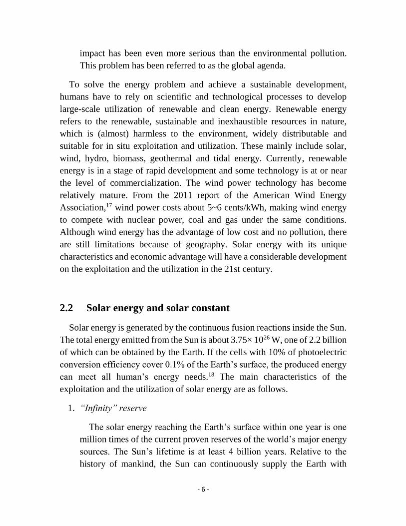
Since the Sun-Earth distance (an average distance of 1.5×10⁸ km) is very
large, the distance can be considered as constant and thus the intensity of solar
radiation outside the Earth’s atmosphere is almost a constant, called the “solar
constant” with the value of 1.338~1.418 kW/m2.19
Fig. 2.1 Solar radiation spectrum at the top of the atmosphere (AM 0) and at the sea level
(AM 1.5)
The Sunlight reaches the Earth’s surface through the atmosphere by the
absorption of the various components of the atmosphere and the reflection
with clouds. The average energy is about 1 kW/m2 while sunlight reaches the
- 8 -
Earth’s surface in the form of direct and diffuse light. Once the photons enter
the atmosphere, the continuous solar spectrum will be divided into spectral
bands due to absorption and scattering of water, carbon dioxide and other
substances. In the spectrum of solar radiation, 99% of the energy concentrates
between 276 nm and 4960 nm (Fig. 2.1).
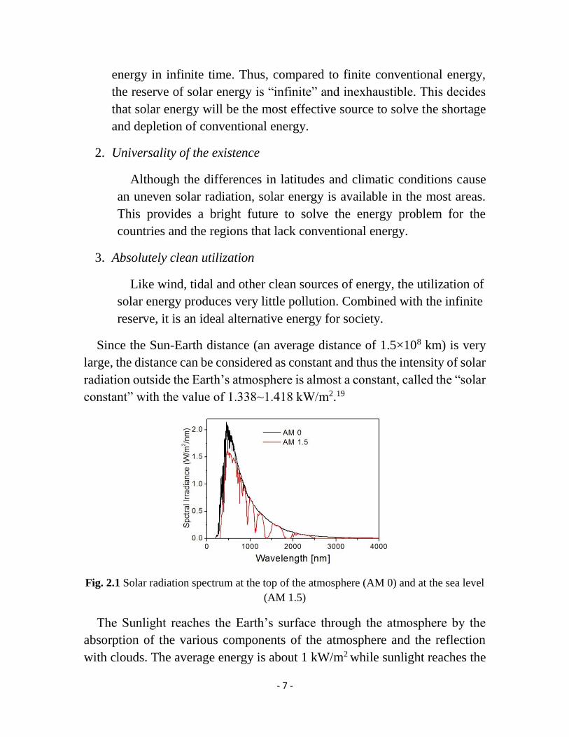
Fig. 2.2 The path length in units of Air Mass
Due to the different angles of incident sunlight resulting in different
thickness of passed atmosphere, the concept of Air Mass (AM) is usually used
to represent the incident path of the sunlight.20 When the vertical irradiation
of the sunlight is outside the atmosphere, AM is 0; when the angle between
the incident sunlight and the ground is 90 º, AM is 1, as shown in Fig. 2.2.
The zenith angle θ is the angle between the connection line of any point at the
sea level with the sun and sea level. The relationship between θ and AM is
expressed as:
AM = 1/sin θ (2.1)
Generally the photovoltaic performance of solar devices are measured
under simulated solar illumination of AM 1.5 with an intensity of 1 kW/m2.
2.3 Utilization of solar energy and development of solar cells
Humans have been constantly looking for effective approaches to utilize
solar energy for a long time. Especially in recent years solar energy has been

- 9 -
vigorously developed due to the problems of the traditional energy depletion
and environmental pollution. The methods of utilization of solar cells are
shown in the following.18
1. Photothermal conversion
Heat utilization occupies an important position in the technology of
solar energy. Solar collectors with air or liquid as a heat transfer media
absorb and store the thermal energy for utilization. Development of new
efficient solar collectors is one of the future directions of the thermal
utilization of solar energy.
2. Photochemical conversion
This conversion relies mainly on the use of solar catalysts producing
other chemical substances or energy carriers by solar illumination. For
example, hydrogen can be manufactured by photochemical cells.
3. Photoelectric conversion
This conversion is achieved by the employment of solar cells, which
are the semiconductor optoelectronic devices based on the photoelectric
or photochemical effects that directly convert the sunlight into electrical
energy. Since the 21st century, the world’s solar photovoltaic industry
and its market has been developed rapidly. Photovoltaic power is likely
to fundamentally change the energy production, supply and consumption
patterns and even bring the revolutionary changes to the energy
development in the near future.
The solar cell is generated by the photovoltaic principle, which has
experienced a long course of development since the 19th century.21 In 1839,
Becquerel first discovered the photoelectric effect by the experiment that CuO
or AgX coated metal electrodes can generate electricity under illumination.
Later, the British scientists Adams and Day obtained 1% of photoelectric
conversion efficiency by the illumination of selenium. After the continuous
effort of scientists, the first practical silicon solar cell was born at Bell Labs
in 1941. By the technological advances the cost of silicon solar cells has
- 10 -
decreased somewhat to meet the needs in specific areas, such as military,
aerospace and the parts of civilian power supplies.
At present, solar cells mainly include the following types according to the
different materials used; silicon solar cells, thin film solar cells, polymer solar
cells, organic solar cells and sensitized solar cells.18 Although the solar cells
based on semiconductor silicon and inorganic semiconductor compounds
have higher conversion efficiency, their complex production process and high
cost limit their development. In recent years, much effort has been devoted to
the sensitized solar cells based on nanocrystal TiO2 electrodes due to low cost.
The sensitized solar cells are divided into two types, dye-sensitized solar cells
(DSCs) with organic dyes as photosensitizers and quantum dots-sensitized
solar cells (QDSCs) with QDs as photosensitizers. Comparing to the DSCs,
QDs have a potential to enhance the cell stability, and their special multi-
electron generation character can enable the theoretically maximum
efficiency to be as high as 44%,14 much higher than that of DSCs.
- 11 -
Chapter 3
Semiconductor and Upconversion Nanoparticles
3.1 Semiconductor Nanoparticles
Semiconductor nanoparticles (NPs) are tiny light-emitting particles with
typical dimensions in the range of 1-100 nm depending on the material. In this
size scale the NPs are located at the transition region between molecular
clusters and bulk materials, resulting in quantum confinement effects.22 When
the radius of an NP is less than the Bohr radius of the exciton (electron-hole
pair) in the bulk material, the charge carriers become spatially confined and
the continuous energy bands of the bulk semiconductor will be split into
discrete energy levels, just like for molecules. The values of energy levels are
ultimately determined by the size of the NPs. As a result, the optical and
electronic properties are also dependent on the size of the NPs.
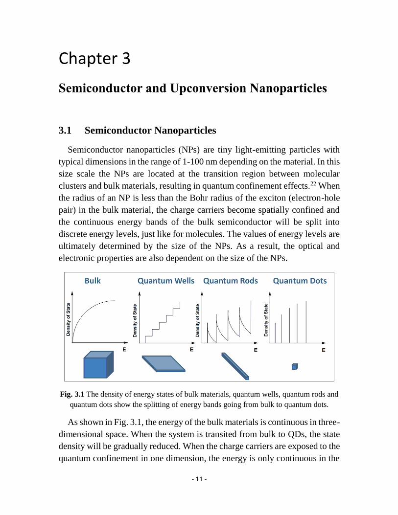
Fig. 3.1 The density of energy states of bulk materials, quantum wells, quantum rods and
quantum dots show the splitting of energy bands going from bulk to quantum dots.
As shown in Fig. 3.1, the energy of the bulk materials is continuous in three-
dimensional space. When the system is transited from bulk to QDs, the state
density will be gradually reduced. When the charge carriers are exposed to the
quantum confinement in one dimension, the energy is only continuous in the
- 12 -
two-dimensional space, so the materials are termed quantum wells or quantum
films. Similarly, when the carriers are confined in the two-dimensional space
and the energy is only one-dimensionally continuous, the materials are
quantum wires or quantum rods (QRs). When the carriers are confined in all
three spatial dimensions, like the movement of carriers limited in a ‘small box’,
we have quantum dots (QDs), whose energy is completely quantized. With
the size decreasing of the material resulting in quantum effects, the structure
and property will shift from macro to micro. QDs have a more obvious
quantum effect than quantum wells and quantum wires, resulting from the
confinement of all three dimensions. The small size and the large specific
surface area of the QDs thus lead to the quantum size-effect and unique optical
properties.
3.1.1 Classification of QDs
In the recent decades, due to the unique electronic and luminescent
properties and the applications in biological labeling, light emitting diodes
and solar cells, QDs have been at the focus of much research attention. QDs,
which, as noted, are semiconductor nanoparticles with a size range from one
to tens of nanometers, consist of several hundreds to millions of atoms. QDs
can be synthesized by chemical methods, known as colloidal QDs, which are
coated by a layer of organic surfactant molecules (also termed ‘ligands’) on
the surface. Since QDs were first discovered by Louis E. Brus in 1982,23 many
types of QDs have been developed, shown in Table 3.1.
- 13 -
Table 3.1 Classification of QDs
Single-core
structure
II-VI CdS,24 CdSe,25,26 CdTe,27,28 ZnSe29
III-V InP,30,31 InAs,32 GaN33
IV-VI PbS,34 PbSe35
IV Ge,36 Si37
Core/shell structure Type-I CdSe/ZnS,38 InP/ZnS,39,40 CdSe/CdS/ZnS,41
CdSe/CdS/Cd0.5Zn0.5S/ZnS42
Type-II CdTe/ CdSe,43 CdSe/ZnTe,43 ZnSe/CdS44
Alloy ZnxCd1-xSe,45 HgxCd1-xTe46
Following to the type of material structures, QDs can be classified as
single-core, core-shells and alloy structured QDs. Furthermore, the single-
core QDs are classified as II-VI, III-V, IV-VI and IV by the elemental
compositions. The core/shell QDs are classified as type-I and type-II
according to the energy band structure of electrons and holes.44 The core/shell
structure consists of a core of semiconductor material surrounded by a 0.5-2
nm thick layer of different semiconductors as a shell. Comparing to the single-
core structure, the core/shell structure can greatly improve the fluorescence
quantum yield (QY) and stability of the QDs.42 Generally, the QY, i.e. the
ratio of emitted photons to absorbed photons through fluorescence 47, is used
to characterize the luminescence efficiency of QDs. Different from the core-
shells QDs, alloy QDs have a homogeneous composition, like single-core
QDs, with three or more chemical elements, the chemical stability and QY of
which are usually higher than those of the single-core QDs.45
Of course, some core/shell QDs can also be classified by their elemental
composition. For example, the type-II core/shell ZnSe/CdS QDs are totally
made of the elements of the II-VI group of elements. Thereby, they can also
be classified as II-VI QDs. In this thesis, most of the prepared QDs belong to
the II-VI group.
- 14 -
3.1.2 Characteristics of QDs
3.1.2.1. Size-dependent effect
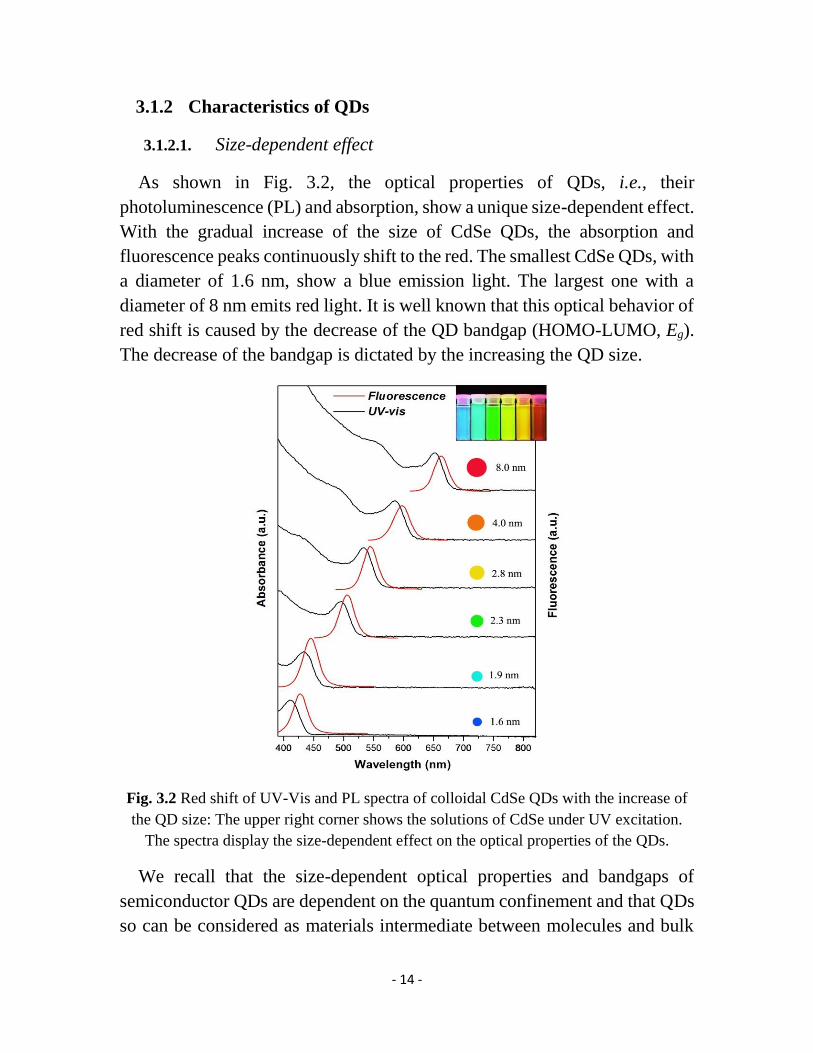
As shown in Fig. 3.2, the optical properties of QDs, i.e., their
photoluminescence (PL) and absorption, show a unique size-dependent effect.
With the gradual increase of the size of CdSe QDs, the absorption and
fluorescence peaks continuously shift to the red. The smallest CdSe QDs, with
a diameter of 1.6 nm, show a blue emission light. The largest one with a
diameter of 8 nm emits red light. It is well known that this optical behavior of
red shift is caused by the decrease of the QD bandgap (HOMO-LUMO, Eg).
The decrease of the bandgap is dictated by the increasing the QD size.
Fig. 3.2 Red shift of UV-Vis and PL spectra of colloidal CdSe QDs with the increase of
the QD size: The upper right corner shows the solutions of CdSe under UV excitation.
The spectra display the size-dependent effect on the optical properties of the QDs.
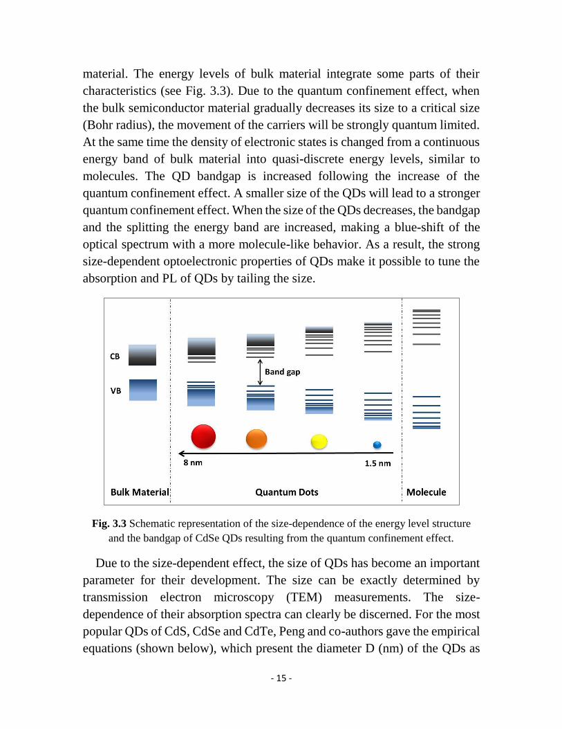
We recall that the size-dependent optical properties and bandgaps of
semiconductor QDs are dependent on the quantum confinement and that QDs
so can be considered as materials intermediate between molecules and bulk
- 15 -
material. The energy levels of bulk material integrate some parts of their
characteristics (see Fig. 3.3). Due to the quantum confinement effect, when
the bulk semiconductor material gradually decreases its size to a critical size
(Bohr radius), the movement of the carriers will be strongly quantum limited.
At the same time the density of electronic states is changed from a continuous
energy band of bulk material into quasi-discrete energy levels, similar to
molecules. The QD bandgap is increased following the increase of the
quantum confinement effect. A smaller size of the QDs will lead to a stronger
quantum confinement effect. When the size of the QDs decreases, the bandgap
and the splitting the energy band are increased, making a blue-shift of the
optical spectrum with a more molecule-like behavior. As a result, the strong
size-dependent optoelectronic properties of QDs make it possible to tune the
absorption and PL of QDs by tailing the size.
Fig. 3.3 Schematic representation of the size-dependence of the energy level structure
and the bandgap of CdSe QDs resulting from the quantum confinement effect.
Due to the size-dependent effect, the size of QDs has become an important
parameter for their development. The size can be exactly determined by
transmission electron microscopy (TEM) measurements. The size-
dependence of their absorption spectra can clearly be discerned. For the most
popular QDs of CdS, CdSe and CdTe, Peng and co-authors gave the empirical
equations (shown below), which present the diameter D (nm) of the QDs as

- 16 -
the function of the wavelength λ (nm) of the first excitonic absorption peak of
the QDs.48 Currently, these equations are widely utilized to calculate the size
of these three types of QDs and the result values give a good agreement with
the experimental values.
CdS: 𝐷 = (−6.6521 × 10⁻⁸)𝜆3 + (1.9557 × 10⁻⁴)𝜆2 − (2.1) (9.2352 × 10⁻²)𝜆 + 13.29
CdSe: 𝐷 = (1.6122 × 10⁻⁹)𝜆4 − (2.6575 × 10⁻⁶)𝜆3 + (2.2) (1.6242 × 10⁻³)𝜆2 − 0.4277𝜆 + 41.57
CdTe: D = (9.8127 × 10⁻⁷)λ3 − (1.7147 × 10⁻³)λ2 + (2.3) 1.0064λ + 194.84
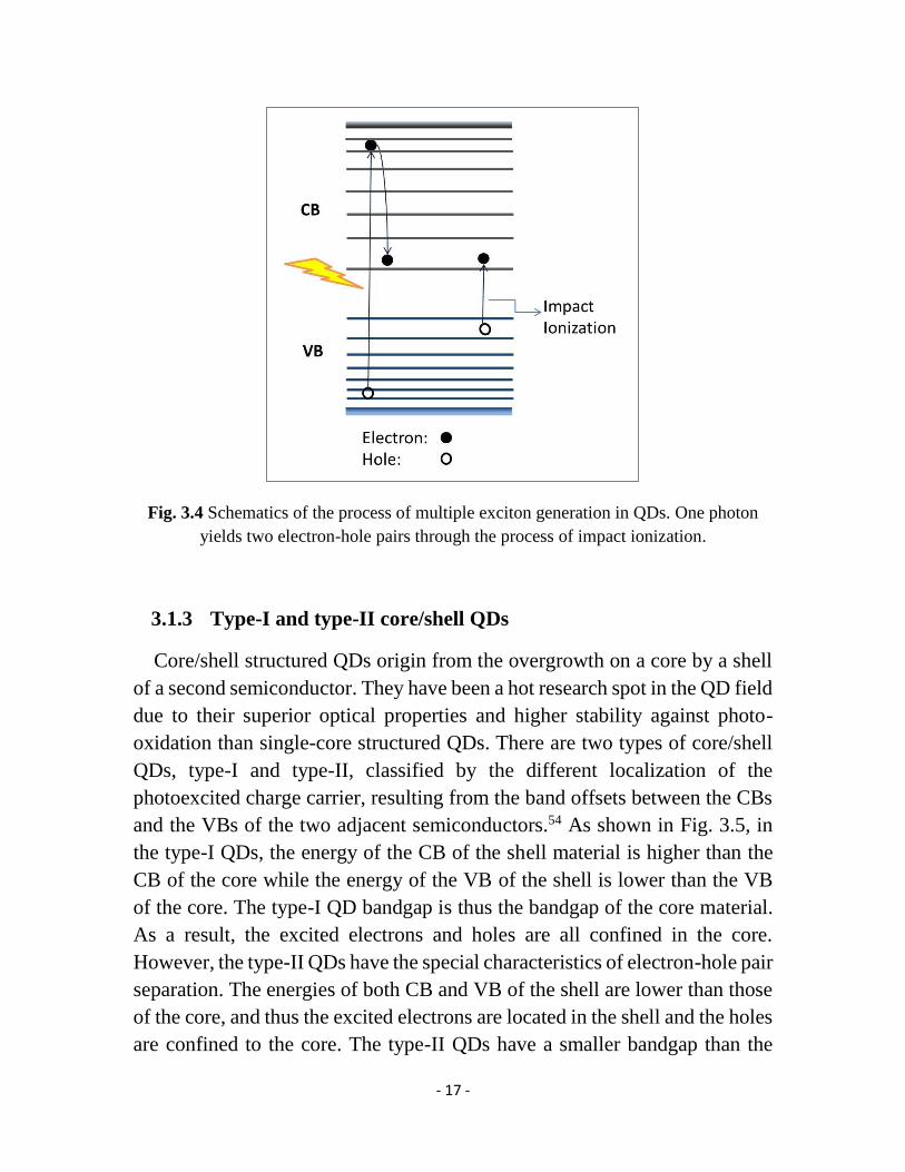
3.1.2.2. Multiple exciton generation
Another unique and valuable property of QDs is the multiple exciton
generation.49,50 Under illumination, an electron from the valence band (VB) is
excited by a high-energy photon, jumps to a high level in the conduction band
(CB), and generates one exciton (electron-hole pair). If the energy of the
photon is at least twice as large as the bandgap of this given QD, the exciton
will have a very high kinetic energy, which can be released to excite another
electron jumping from the VB to the CB by impact ionization. As a result, one
photon now generates two excitons as the process shown in Fig 3.4, allowing
the internal quantum efficiency to go beyond 100%. Note that the quantum
efficiency (QE) is the ratio between the number of photogenerated excitons
and the number of the incident photons. Certainly more excitons can be
generated if the energy of the photon is high enough. So far, multiple exciton
behavior with high QE has been observed in PbS,14 PbSe51 and CdSe/ZnS
(core/shell) QDs.52 Therefore, this property of QDs is helpful to increase the
efficiency of QD-based photovoltaics and light-emitting devices. For example,
the theoretical maximum efficiency (44%) of QDSCs is higher than that of
DSCs.14 An incident photon to current conversion efficiency (IPCE) of over
100% in PbS based QDSCs has been observed, which was attributed to this
multiple exciton generation effect.53
- 17 -
Fig. 3.4 Schematics of the process of multiple exciton generation in QDs. One photon
yields two electron-hole pairs through the process of impact ionization.
3.1.3 Type-I and type-II core/shell QDs
Core/shell structured QDs origin from the overgrowth on a core by a shell
of a second semiconductor. They have been a hot research spot in the QD field
due to their superior optical properties and higher stability against photo-
oxidation than single-core structured QDs. There are two types of core/shell
QDs, type-I and type-II, classified by the different localization of the
photoexcited charge carrier, resulting from the band offsets between the CBs
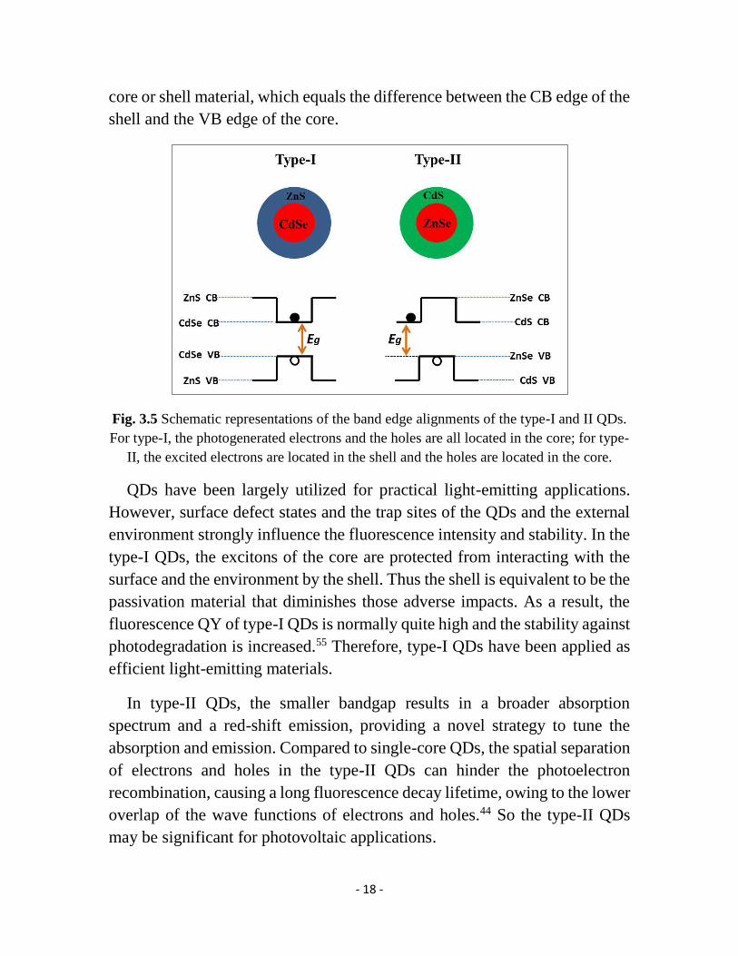
and the VBs of the two adjacent semiconductors.54 As shown in Fig. 3.5, in
the type-I QDs, the energy of the CB of the shell material is higher than the
CB of the core while the energy of the VB of the shell is lower than the VB
of the core. The type-I QD bandgap is thus the bandgap of the core material.
As a result, the excited electrons and holes are all confined in the core.
However, the type-II QDs have the special characteristics of electron-hole pair
separation. The energies of both CB and VB of the shell are lower than those
of the core, and thus the excited electrons are located in the shell and the holes
are confined to the core. The type-II QDs have a smaller bandgap than the
- 18 -
core or shell material, which equals the difference between the CB edge of the
shell and the VB edge of the core.
Fig. 3.5 Schematic representations of the band edge alignments of the type-I and II QDs.
For type-I, the photogenerated electrons and the holes are all located in the core; for type-
II, the excited electrons are located in the shell and the holes are located in the core.
QDs have been largely utilized for practical light-emitting applications.
However, surface defect states and the trap sites of the QDs and the external
environment strongly influence the fluorescence intensity and stability. In the
type-I QDs, the excitons of the core are protected from interacting with the
surface and the environment by the shell. Thus the shell is equivalent to be the
passivation material that diminishes those adverse impacts. As a result, the
fluorescence QY of type-I QDs is normally quite high and the stability against
photodegradation is increased.55 Therefore, type-I QDs have been applied as
efficient light-emitting materials.
In type-II QDs, the smaller bandgap results in a broader absorption
spectrum and a red-shift emission, providing a novel strategy to tune the
absorption and emission. Compared to single-core QDs, the spatial separation
of electrons and holes in the type-II QDs can hinder the photoelectron
recombination, causing a long fluorescence decay lifetime, owing to the lower
overlap of the wave functions of electrons and holes.44 So the type-II QDs
may be significant for photovoltaic applications.
- 19 -
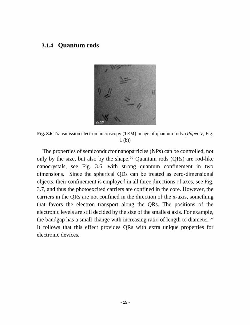
3.1.4 Quantum rods
Fig. 3.6 Transmission electron microscopy (TEM) image of quantum rods. (Paper V, Fig.
1 (b))
The properties of semiconductor nanoparticles (NPs) can be controlled, not
only by the size, but also by the shape.56 Quantum rods (QRs) are rod-like
nanocrystals, see Fig. 3.6, with strong quantum confinement in two
dimensions. Since the spherical QDs can be treated as zero-dimensional
objects, their confinement is employed in all three directions of axes, see Fig.
3.7, and thus the photoexcited carriers are confined in the core. However, the
carriers in the QRs are not confined in the direction of the x-axis, something
that favors the electron transport along the QRs. The positions of the
electronic levels are still decided by the size of the smallest axis. For example,
the bandgap has a small change with increasing ratio of length to diameter.57
It follows that this effect provides QRs with extra unique properties for
electronic devices.
- 20 -
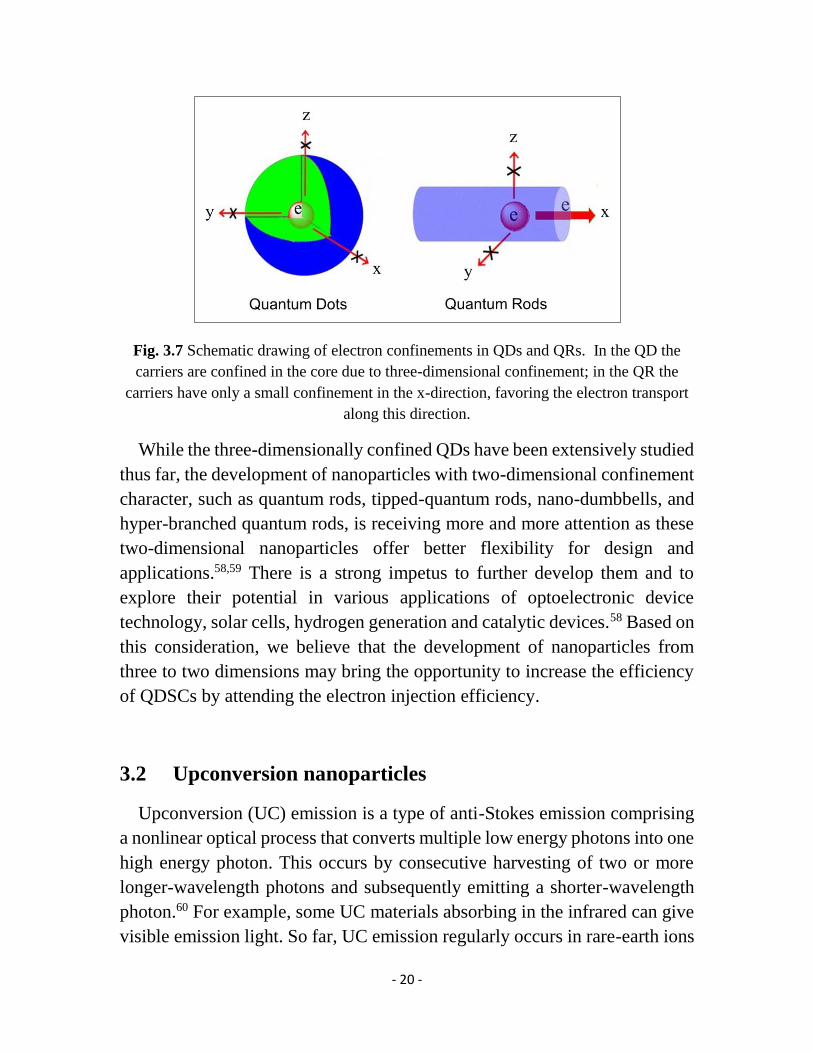
Fig. 3.7 Schematic drawing of electron confinements in QDs and QRs. In the QD the
carriers are confined in the core due to three-dimensional confinement; in the QR the
carriers have only a small confinement in the x-direction, favoring the electron transport
along this direction.
While the three-dimensionally confined QDs have been extensively studied
thus far, the development of nanoparticles with two-dimensional confinement
character, such as quantum rods, tipped-quantum rods, nano-dumbbells, and
hyper-branched quantum rods, is receiving more and more attention as these
two-dimensional nanoparticles offer better flexibility for design and
applications.58,59 There is a strong impetus to further develop them and to
explore their potential in various applications of optoelectronic device
technology, solar cells, hydrogen generation and catalytic devices.58 Based on
this consideration, we believe that the development of nanoparticles from
three to two dimensions may bring the opportunity to increase the efficiency
of QDSCs by attending the electron injection efficiency.
3.2 Upconversion nanoparticles
Upconversion (UC) emission is a type of anti-Stokes emission comprising
a nonlinear optical process that converts multiple low energy photons into one
high energy photon. This occurs by consecutive harvesting of two or more
longer-wavelength photons and subsequently emitting a shorter-wavelength
photon.60 For example, some UC materials absorbing in the infrared can give
visible emission light. So far, UC emission regularly occurs in rare-earth ions
- 21 -
doped compounds. Er3+ and Yb3+ co-doped NaYF4 (NaYF4:Er3+/Yb3+)
nanoparticles is a typical UC material, where NaYF4 is the most efficient host
material for UC emission. The Yb3+ ions play the role as sensitizer to harvest
the excitation light and the Er3+ ions plays the role of receiving the energy
from the Yb3+ ions, and emitting the UC luminescence subsequently. Due to
their unique luminescent and chemical properties, UC nanoparticles have
been successfully applied in many technological areas, such as bioimaging,
security and displays, and solar cells.
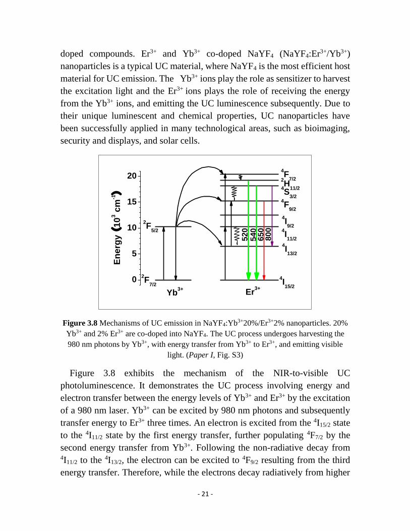
Figure 3.8 Mechanisms of UC emission in NaYF4:Yb3+20%/Er3+2% nanoparticles. 20%
Yb3+ and 2% Er3+ are co-doped into NaYF4. The UC process undergoes harvesting the
980 nm photons by Yb3+, with energy transfer from Yb3+ to Er3+, and emitting visible
light. (Paper I, Fig. S3)
Figure 3.8 exhibits the mechanism of the NIR-to-visible UC
photoluminescence. It demonstrates the UC process involving energy and
electron transfer between the energy levels of Yb3+ and Er3+ by the excitation
of a 980 nm laser. Yb3+ can be excited by 980 nm photons and subsequently
transfer energy to Er3+ three times. An electron is excited from the 4I15/2 state
to the 4I11/2 state by the first energy transfer, further populating 4F7/2 by the
second energy transfer from Yb3+. Following the non-radiative decay from 4I11/2 to the 4I13/2, the electron can be excited to 4F9/2 resulting from the third
energy transfer. Therefore, while the electrons decay radiatively from higher
0
5
10
15
20
800
650
540
4F
7/2
2F
5/2
2F
7/2
4I15/2
Er3+
Yb3+
En
erg
y (
10
3 c
m-1)
2H
11/24S
3/2
4I11/2
4F
9/2
4I9/2
4I13/2
520

- 22 -
states to the ground state, the Er3+ ions can give emission at three different
shorter wavelengths in the visible spectrum.

- 23 -
Chapter 4
Sensitized Solar Cells
4.1 Development of sensitized solar cells
4.1.1 Quantum dot sensitized solar cells
Kamat and co-workers first proposed that quantum dot sensitized solar cells
(QDSCs) have a similar working mechanism as dye-sensitized solar cells
(DSCs).61 Comparing to the DSCs, QDs take the place of the organic dye as
photosensitizer. In the recent several years there have been considerable
progresses to improve the photovoltaic performance. CdSe QDs is a most
popular and efficient sensitizer used in QDSCs. The efficiency of CdSe
QDSCs has been increased to more than 5% by optimizing the QDs quality,
by improving the effective deposition technique of QDs onto TiO2, and by
choosing efficient counter electrode materials.62,63 Besides, the traditional
QDs like CdSe and CdS, some other kinds of QD solar cells have been rapidly
developed.
Doping is a strategy to tune the electronic and optical properties of the QDs.
Mn-doped CdS QDs can produce intermediate electronic states inside CdS,
which are located between the conduction band (CB) of the QDs and the CB
of TiO2, as controlled by the percentage of the Mn2+ dopant. The intermediate
states facilitate the electron collecting, and inhibit the electron recombination
with the holes of the CdS QDs and the electrolyte, leading to that the
efficiency of the CdS/CdSe QDSCs significantly increases from 4.2% to
5.4%.64 PbS QDSCs have been the target for another intensive research focus
due to the low bandgap of PbS QDs which spreads its absorption spectrum to
the NIR range. However, due to the heavy charge recombination and stability
problems, PbS QDSCs present a very low performance. Recently the group
of Park reported a kind of Hg-doped PbS QDSCs that give the remarkably
high current density of 30 mA/cm2 and a conversion efficiency of 5.6%. The
- 24 -
doping of Hg2+ into PbS can make PbS CB move to the high energy level,
which enhances the electron injection from the PbS CB to the TiO2 CB, and
restrains the charge recombination.65
As described in section 3.1.3, the core/shell heterostructure QDs may be a
promising candidate for photovoltaic devices due to their unique charge
distribution. Our group was the first to apply type-II QDs into QDSCs, where
we used colloidal core/shell ZnSe/CdS QDs as photosensitizer. Type-II QDs
can broaden the absorption spectrum without decreasing the CB of the QDs
and favor the charge extraction (Paper IV). Moreover, inverted type-I
colloidal CdS/CdSe QDs were developed for the QDSCs, which also facilitate
the charge extraction and improve the electron injection and hole transfer,
resulting in a conversion efficiency of 5.3%.66
High-quality alloy QDs were developed in this thesis work for QDSC
applications, motivated by that their optical and electronic properties can be
tuned by controlling the proportion of the component elements of the QD
alloys rather than by changing the QDs size. The group of Kamat
successfully synthesized three types of ternary-alloy CdSeS QDs, which emit
green, orange and red light, respectively, by adjusting the ratio of Se and S,
with a similar diameter of 4.5 nm. Three types of CdSeS QDs were deposited
onto TiO2 sequentially in order of green, orange and red QDs, leading to a 3%
of conversion efficiency.67 The group of Zhong reported a kind of CdSeTe
alloy QDSC that gave an excellent performance of more than 6% efficiency
and high stability. The bandgap of the employed CdSe0.45Te0.55 QDs with only
5 nm diameter is narrower than that of the corresponding CdSe and CdTe QDs,
leading to an extension of the adsorption spectrum to around 800 nm.68
The development described above regards QDSCs based on liquid
electrolytes, thus termed liquid-state QDSCs. In the recent decade, solid-state
sensitized solar cells (SSCs) with solid-state hole transport materials (HTMs)
as electrolytes have increasingly attracted attention due to their stability and
practicality.69,70 For the solid-state QDSCs, the group of Seok published
several research achievements regarding Sb3S2 QDs sensitized solid-state
solar cells with some conducting polymers acting as the HTMs. Through the
continuous development, an impressive conversion efficiency of 6.3% was

- 25 -
obtained.15,71,72 CH3NH3PbX3(X=Cl, Br, I) perovskites-sensitized solar cells
with spiro-MeOTAD as the HTM have been at the focus of research in the
field of solid-state solar cells in the recent several years. This perovskite,
quantum-dot-like, nanoparticles are a kind of organic-inorganic hybrid
material with a high absorption coefficient. Such perovskites-sensitized solar
cells have frequently offered surprises to researchers. The conversion
efficiency was improved most recently from 9.7% to a record of 15% for
sensitized solar cells.73-75
4.1.2 DSCs with upconversion materials for energy relay
Dye-sensitized solar cells (DSCs) using organic dyes as sensitizers are one
of the promising alternatives for silicon-based solar cells due to their low cost
and relatively high conversion efficiency.2 Currently their highest efficiency
is up to more than 12% as obtained by two strategies. One is to co-sensitize a
porphyrin dye and an organic dye onto the TiO2 photoelectrode combined
with a novel cobalt redox couple.3 The other strategy is to employ an NIR
organic dye and an N719 dye for a tandem-like stacked DSC.4 The efficiency
value still has room for further increase by extending the light-harvesting into
the NIR spectrum, as the NIR light accounts for nearly half of the energy of
the sun irradiation. One strategy is to develop NIR organic sensitizers.
However, NIR dyes do not really match the requirements of DSCs due to the
low electron injection efficiency and the heavy charge recombination.76
The strategy of energy relay was introduced by McGehee and Grätzel et al.
They used a highly photoluminescent dye as energy relay material to transfer
short wavelength solar energy to the sensitized dye by the process of Förster
resonant energy transfer (FRET).77 To fulfill the FRET process, the emission
spectrum of the energy relay dye should match the absorption spectrum of the
sensitized dye. Although only conversion of solar energy in the visible
spectrum was reported, the principle of energy relay is highly feasible to
extend the light-harvesting spectrum to the NIR range by employing the
upconversion (UC) materials that absorb NIR light and emit converted visible
light.
- 26 -
As far as my knowledge, Demopoulos and co-workers were the first to
introduce an UC material to the DSC field by doping it into a TiO2 electrode.78
The photocurrent response was observed under the illumination of a 980 nm
laser. Our group utilized a kind of small-size colloidal UC nanoparticles with
high conversion efficiency deposited onto the dye-sensitized TiO2 film. A
high photocurrent was obtained under the similar illumination intensity of 980
nm. We found that the UC nanoparticles can also act as scattering centers to
enhance the solar cell performance under simulated irradiation (Paper I).
Liang et al. developed a core/double-shell-structured UC material mixed with
TiO2 together as photoelectrode. The UC material as scattering and UC
centers lead to an enhancement of the efficiency of solar cells.79 Chang et al.
developed an UC nanoparticle/TiO2 nano-heterostructure photoelectrode,
where direct electron injection from UC nanoparticles to TiO2 was found.80
4.2 Working principle and basic components of SSCs
4.2.1 Working principle
4.2.1.1. QDSCs
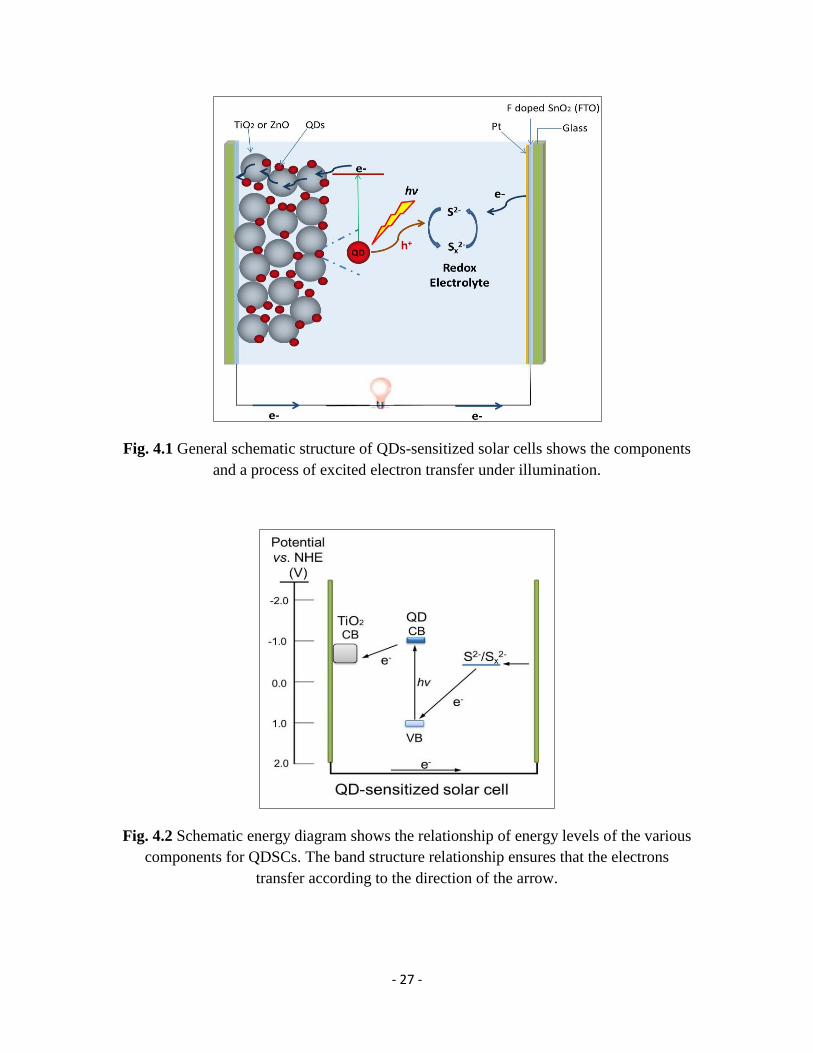
The basic structure of QDSCs is shown in Fig. 4.1. It mainly consists of
three parts: working electrode, electrolyte and counter electrode.81 The
working electrode, that is a photoelectrode or photoanode, is generally
fabricated through the deposition of a layer of a mesoporous nanocrystalline
semiconductor material (TiO2 or ZnO) on a conductive substrate (e.g. FTO
and ITO glass), followed by adsorption of QDs onto the mesoporous
semiconductor. The electrolyte is normally a liquid containing a redox couple
(S2-/Sx2-), filling in between the working electrode and the counter electrode
to transport carriers. The counter electrode, i.e. the cathode, is a passive
electrode, normally a conductive glass coated with a layer of catalyst (Pt, Au,
Cu2S), for the charge exchange between counter electrode and electrolyte.
- 27 -
Fig. 4.1 General schematic structure of QDs-sensitized solar cells shows the components
and a process of excited electron transfer under illumination.
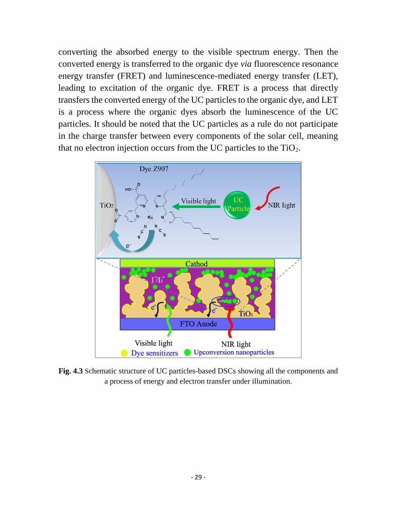
Fig. 4.2 Schematic energy diagram shows the relationship of energy levels of the various
components for QDSCs. The band structure relationship ensures that the electrons
transfer according to the direction of the arrow.

- 28 -
Fig. 4.1 and the energy diagram of Fig. 4.2, depicting the QDSCs, show
schematically how the QDs generate excitons under illumination with
sunlight and how the excited electrons then are injected from the CB of QDs
into the CB of TiO2. At the same time, the photogenerated holes are donated
to the electrolyte and thus the QDs are restored. The oxidation species of the
electrolyte diffuses to the counter electrode and is reduced by the migrated
electrons from the external circuit.
The above process can be expressed as the following: 12,61,82
Photoanode: (e is the electron; h is the hole)
𝑄𝐷𝑠 + ℎ𝑣 → 𝑄𝐷𝑠(𝑒 + ℎ) (4.1)
𝑄𝐷𝑠(𝑒) + 𝑇𝑖𝑂2 → 𝑄𝐷𝑠 + 𝑇𝑖𝑂2(𝑒) (4.2)
𝑄𝐷𝑠(ℎ) + 𝑆2− → 𝑄𝐷𝑠 + 𝑆 (4.3)
Electrolyte:
𝑆 + 𝑆𝑥−1 2− → 𝑆𝑥
2− (𝑥 = 2 − 5) (4.4)
Counter electrode:
𝑆𝑥2− + 2𝑒 → 𝑆𝑥−1
2− + 𝑆2− (4.5)
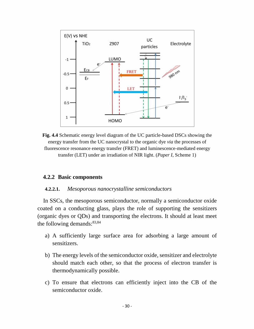
4.2.1.2. UC-particle-based DSCs
The structure of the DSCs with the UC nanoparticles as energy relay
material is shown in Fig. 4.3. It is similar to the QDSC described above except
that an organic dye as photosensitizer is bound onto the TiO2 particle and that
subsequently the UC nanoparticles are deposited onto the dye-sensitized TiO2
film. Different from the QDSCs, one commonly uses the I-/I3- redox couple as
electrolyte for this type of solar cell. The organic dye just only harvests the
visible light and the UC particle harvests the NIR light.
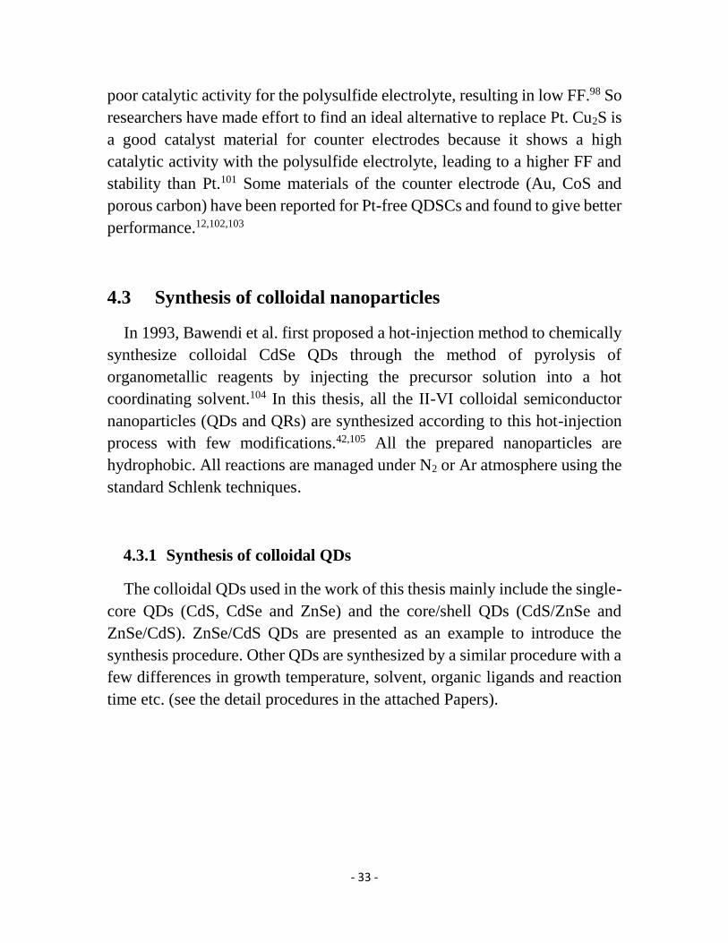
Combined with the energy level diagram of Fig. 4.4, we can get to know
that the UC particles are excited under NIR illumination, followed by
- 29 -
converting the absorbed energy to the visible spectrum energy. Then the
converted energy is transferred to the organic dye via fluorescence resonance
energy transfer (FRET) and luminescence-mediated energy transfer (LET),
leading to excitation of the organic dye. FRET is a process that directly
transfers the converted energy of the UC particles to the organic dye, and LET
is a process where the organic dyes absorb the luminescence of the UC
particles. It should be noted that the UC particles as a rule do not participate
in the charge transfer between every components of the solar cell, meaning
that no electron injection occurs from the UC particles to the TiO2.
Fig. 4.3 Schematic structure of UC particles-based DSCs showing all the components and
a process of energy and electron transfer under illumination.
- 30 -
Fig. 4.4 Schematic energy level diagram of the UC particle-based DSCs showing the
energy transfer from the UC nanocrystal to the organic dye via the processes of
fluorescence resonance energy transfer (FRET) and luminescence-mediated energy
transfer (LET) under an irradiation of NIR light. (Paper I, Scheme 1)
4.2.2 Basic components
4.2.2.1. Mesoporous nanocrystalline semiconductors
In SSCs, the mesoporous semiconductor, normally a semiconductor oxide
coated on a conducting glass, plays the role of supporting the sensitizers
(organic dyes or QDs) and transporting the electrons. It should at least meet
the following demands:83,84
a) A sufficiently large surface area for adsorbing a large amount of
sensitizers.
b) The energy levels of the semiconductor oxide, sensitizer and electrolyte
should match each other, so that the process of electron transfer is
thermodynamically possible.
c) To ensure that electrons can efficiently inject into the CB of the
semiconductor oxide.

- 31 -
d) Electrons in the semiconductor have a faster transfer speeds and thus
reduce the electron recombination with electrolyte.
Fig.4.5 SEM image of the TiO2 mesoporous film
Good photostability, appropriate bandgap and excellent photocatalytic
performance make the nanocrystalline TiO2 to perform as one of the best
semiconductor electrode materials. Fig 4.5 is a typical image of a scanning
electron microscopy (SEM) recording of a TiO2 film with a mesoporous
structure. Furthermore, the photoconversion efficiency can be developed by
using TiO2 nanotubes as working electrode due to the fast rate of electron
transport in the TiO2 nanotube. In addition, ZnO with a wide bandgap similar
to TiO2, is also a good choice as electrode materials.85,86
4.2.2.2. QD sensitizers
In the past ten years, many kinds of QDs were used in QDSCs, such as
CdS,87 CdSe,88 CdTe,89 PbS,11 Sb2S3,15 Bi2S3,
90 Ag2S91 and InP.92 In the QDSC
system, the sensitizer QDs play a role of energy collectors like light-
harvesting antenna.11 Their performance have a direct impact on the
photoelectric conversion of the QDSCs and thus QDs themselves are the most
important part that ensure the efficient work of QDSCs. The high molar
extinction coefficient makes QDs to efficiently harvest light in the visible area.
Due to the tunable bandgap, the CBs of QDs can match the CB of TiO2 and
thereby ensure the effective electron transfer from the QDs to TiO2.
Furthermore, QDs give a high theoretical efficiency for QDSCs because of
their multiple-exciton effect. QDs also have a better photochemical stability
compared to organic dyes.12

- 32 -
4.2.2.3. Electrolyte
The electrolyte generally contains a redox couple including a reduction and
an oxidation species, which is an important part of the QDSCs to ensure that
the cells work normally. When the excited electrons are injected into the CB
of the TiO2 from the QDs, the QDs are oxidized. In order to make the
photoelectric conversion occur continuously, the QDs should be regenerated
by the redox couple in the electrolyte. The I-/I3- redox couple is the mostly
used one for DSCs.5 It may quickly restore the oxidized dye and thus
effectively inhibit the charge recombination on the electrode surface.
Unfortunately, its corrosion leads to a quick decomposition of the QDs,
thereby causing a large decrease of the photovoltaic efficiency and
lifetime.93,94 In order to replace the iodide electrolyte, an inorganic redox
couple, polysulfide (S2-/Sx2-), has mostly been employed in QDSCs. It is not
corrosive to the QDs and can give a stable photovoltaic performance and
increase of the lifetime for QDSCs.10,84,95 However, QDSCs using S2-/Sx2- as
electrolyte show a lower open-circuit voltage (Voc) and fill factor (FF) than
those with the I-/I3- electrolyte.96 These problems may be the result of the
higher redox potential (-0.45 V vs. NHE) compared to I-/I3- (+0.35 V vs. NHE)
and low activity with counter electrode, such as Pt.97,98
The group of Grätzel developed a cobalt redox couple (Co2+/Co3+) as
electrolyte for QDSCs.3,99,100 For the CdSe based QDSCs, it can ensure that
the solar cells are stable. It was shown that the short-circuit current (Jsc)
decreased less than 20% after 6 weeks. However, the complexity of their
synthesis limits their application in QDSCs.
So the development of a stable and commercially available electrolyte is an
effective way to improve the performance of QDSCs. We have developed two
pure organic electrolytes for QDSCs, see the detailed discussion in section 5.4.
4.2.2.4. Counter electrode
The role of the counter electrode is to catalyze the reduction of the redox
couple in the electrolyte. Because the catalytic reduction of Platinum (Pt) to
the iodine electrolyte is relatively strong, the common electrode is prepared
by depositing a layer of Pt on FTO conductive glass. However, Pt produces a
- 33 -
poor catalytic activity for the polysulfide electrolyte, resulting in low FF.98 So
researchers have made effort to find an ideal alternative to replace Pt. Cu2S is
a good catalyst material for counter electrodes because it shows a high
catalytic activity with the polysulfide electrolyte, leading to a higher FF and
stability than Pt.101 Some materials of the counter electrode (Au, CoS and
porous carbon) have been reported for Pt-free QDSCs and found to give better
performance.12,102,103
4.3 Synthesis of colloidal nanoparticles
In 1993, Bawendi et al. first proposed a hot-injection method to chemically
synthesize colloidal CdSe QDs through the method of pyrolysis of
organometallic reagents by injecting the precursor solution into a hot
coordinating solvent.104 In this thesis, all the II-VI colloidal semiconductor
nanoparticles (QDs and QRs) are synthesized according to this hot-injection
process with few modifications.42,105 All the prepared nanoparticles are
hydrophobic. All reactions are managed under N2 or Ar atmosphere using the
standard Schlenk techniques.
4.3.1 Synthesis of colloidal QDs
The colloidal QDs used in the work of this thesis mainly include the single-
core QDs (CdS, CdSe and ZnSe) and the core/shell QDs (CdS/ZnSe and
ZnSe/CdS). ZnSe/CdS QDs are presented as an example to introduce the
synthesis procedure. Other QDs are synthesized by a similar procedure with a
few differences in growth temperature, solvent, organic ligands and reaction
time etc. (see the detail procedures in the attached Papers).

- 34 -
Fig.4.6 Schematic reaction device (left) of colloidal QDs by the hot-inject method and
the reaction pathway (right) of colloidal ZnSe QDs.
Type-II ZnSe/CdS core/shell QDs were synthesized by a two-step process,
which consists of the growth and purification of ZnSe QDs as a core, followed
by the growth of a CdS shell.
Fig 4.7 TEM image of ZnSe/CdS QDs (Paper IV, Fig. 1)
Synthesis of ZnSe cores: To form the pure crystals with high quality, the
hot-injection process was adopted to synthesize ZnSe QDs, i.e. heating a
reactant precursor (Zn-precursor) to a quite high temperature and then
injecting another precursor (Se-precursor) into it, as shown in Fig. 4.6. The
typical synthesis process is as follows.

- 35 -
Zinc oxide and stearic acid were dissolved in non-coordinating solvent
octadecene (ODE) by heating the reagents to 280 ºC in a three-necked flask
under N2 flow, while keeping stir. After the mixture (Zn-precursor) was totally
dissolved as a clear solution, a selenium stock solution (Se-precursor) was
injected quickly into the reaction flask, prepared by dissolving selenium
powder in trioctylphosphine (TOP). A temperature of 270–280 ºC was kept
during the nanocrystal growth. The reaction was terminated after some
minutes by removing the heating mantle. Some hexane was added when the
mixture was cooled to 60 ºC. The residual reagent was removed by washing
the reaction mixture with methanol several times.
Deposition of CdS shells: The CdS shell growth was accomplished by the
technique of successive ion layer adsorption reactions (SILAR),44 which is
used by alternately injecting cadmium and sulfur precursors into the solution
with the prepared CdS core QDs in 1-octadecanamine (ODA) and ODE at
190~210 ºC. To prevent the formation of CdSe interlayers between the ZnSe
core and CdS shells, the sulfur precursor was injected first. The cadmium and
sulfur precursors were prepared by dissolving CdO in oleic acid (OA) and
ODE and dissolving sulfur in ODE, respectively. During the SILAR
procedure, sulfur and cadmium precursors were injected in sequences during
10 min, respectively. Repeating the procedure two or three times to give two
or three layers of CdS shell and the deposition was ended when the QDs
reached the targeted size. The reaction mixture was kept in 190 ºC for 30 min
and the washing process was carried out in order to obtain the desired
ZnSe/CdS core/shell QDs (TEM image shown in Fig. 4.7).
4.3.2 Synthesis of QRs
Synthesis of CdS/CdSe QRs: Firstly CdS QDs as a seed should be
synthesized in advance. The reaction process was similar to that of ZnSe.
Subsequently, in the growth of CdSe shells of rods on the CdS seed, the
SILAR method was used by alternately injecting cadmium and selenium
precursors into the solution with CdS core QDs in OA and ODE at 190 ~210
ºC. The cadmium and selenium precursors were prepared by dissolving CdO
- 36 -
in oleic acid and ODE and dissolving selenium in TOP and ODE, respectively.
In the SILAR procedure, selenium and cadmium precursors were injected in
sequences during 5~10 min, respectively, and then the procedure was repeated
one or two times. After these steps, the reaction mixture was kept in 190 ºC
for 30 min, followed by the washing process in order to obtain the desired
quantum rods, whose TEM image is shown in Fig. 3.6.
4.3.3 Synthesis of colloidal UC nanoparticles
The colloidal UC nanoparticles employed in this thesis are synthesized by
a similar method as for the QD synthesis, i.e. by hot-injection and pyrolysis
of organometallic reagents. The synthesis of UC particles was done by the
coauthors in Prof. Paras N. Prasad’s group. The detailed synthesis process can
be found in Papers I and II.
4.4 Fabrication and assembly of sensitized solar cells
4.4.1 Fabrication of TiO2 photoelectrode
The typical TiO2 electrode was fabricated according to the procedure
reported in the literature 82 with few modifications. The TiO2 film (about 12
mm thick) is made by doctor-blading the nanocrystalline TiO2 colloidal
solution onto a cleaned conducting glass surface with a layer of Fluoride-
doped tin oxide (FTO), followed by the sintering at 450 ºC for 30 min. After
the sintering, a final treatment is carried out, where the sintered TiO2 film is
immersed in a 40 mM TiCl4 aqueous solution at 70 ºC for half an hour,
followed by washing the film with deionized water and re-sintering at 450 ºC
for 30 min. A uniform dispersion of TiO2 colloidal solution is prepared by
mixing and grinding a mixture with the commercial P25 TiO2, acetylacetone,
deionized water and a surfactant of Triton X-100.
- 37 -
4.4.2 QD deposition onto photoelectrode
Usually there are two common methods to deposit QDs on a photoelectrode.
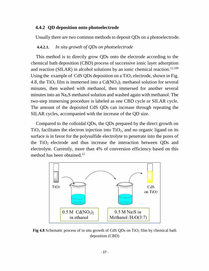
4.4.2.1. In situ growth of QDs on photoelectrode
This method is to directly grow QDs onto the electrode according to the
chemical bath deposition (CBD) process of successive ionic layer adsorption
and reaction (SILAR) in alcohol solutions by an ionic chemical reaction.12,100
Using the example of CdS QDs deposition on a TiO2 electrode, shown in Fig.
4.8, the TiO2 film is immersed into a Cd(NO3)2 methanol solution for several
minutes, then washed with methanol, then immersed for another several
minutes into an Na2S methanol solution and washed again with methanol. The
two-step immersing procedure is labeled as one CBD cycle or SILAR cycle.
The amount of the deposited CdS QDs can increase through repeating the
SILAR cycles, accompanied with the increase of the QD size.
Compared to the colloidal QDs, the QDs prepared by the direct growth on
TiO2 facilitates the electron injection into TiO2, and no organic ligand on its
surface is in favor for the polysulfide electrolyte to penetrate into the pores of
the TiO2 electrode and thus increase the interaction between QDs and
electrolyte. Currently, more than 4% of conversion efficiency based on this
method has been obtained.12
Fig 4.8 Schematic process of in situ growth of CdS QDs on TiO2 film by chemical bath
deposition (CBD)

- 38 -
4.4.2.2. Deposition by a bifunctional linker molecule
This method is to connect the pre-synthesized colloidal QDs with the
photoelectrode material by a bifunctional linker molecule.61,82 Usually this
molecule (HOOC-R-SH) consists of a carboxylate and a thiol functional
group at its both terminals. The carboxylate group is used to bind to the
electrode and the thiol group is attached to the QDs. We always utilize the
mercaptopropionic acid (MPA, HOOC-C2H4-SH) as a linker. The typical
process is that the TiO2 electrodes are immersed in a 1 M MPA acetonitrile
solution for 12 h, and then transferred to the QD toluene solution for 1~2 days,
as schematically shown in Fig. 4.9.
Compared to the direct growth of QDs which is associated with the
difficulty of controlling the size distribution of the QDs on TiO2, deposition
of colloidal QDs can provide uniform and precise morphological
characteristics in shape and size. Sometimes these two methods are used
together to prepare the QD-coated photoelectrode. For example, the colloidal
CdSe QDs are deposited on the TiO2 film by a linker, followed by the
deposition of the directly grown CdSe using the SILAR method. Such
assembled solar cells show a better conversion efficiency.106
Fig 4.9 Schematic process of the connection between TiO2 and QDs with a bifunctional
molecule MPA as a linker. The carboxylate group of MPA is bound to TiO2 and its thiol
group is attached to the QD.

- 39 -
In the fabrication of QDSCs, a layer of ZnS is always deposited on the QD-
coated photoelectrode by the SILAR method.107 With the ZnS coating, the
conversion efficiency of the QDSCs can be increased substantially. Firstly,
ZnS can passivate the surface of the QDs and thus inhibit the carrier loss due
to the surface trapping of the QDs. Secondly, because of the wide bandgap of
ZnS its CB higher is than the CB of most of the QDs, leading to that ZnS can
efficiently suppress the recombination of the photoexcited electron at the
interface between photoelectrode and electrolyte. Moreover, ZnS can increase
the chemical stability of the QDSCs.
4.4.3 Fabrication of counter electrode
The counter electrode loading a catalytic amount of Pt is prepared as
followed.108 Firstly H2PtCl6 is dissolved into isopropyl alcohol to prepare a
solution (3% by mass). Sequentially a small amount of solution is dropped on
the surface of FTO glass with a predrilled hole, followed by rolling with a
glass rod on the surface to get a uniform coating. After drying, the electrode
is sintered at 400 ºC for 20~30 min, leading to the thermal decomposition of
H2PtCl6 into Pt.
The Cu2S counter electrode is prepared as followed. A brass foil is cleaned
by deionized water under ultrasonic condition, followed by immersing in
hydrochloric acid solution at 70 ºC for 5 min. The immersed foil is washed
with deionized water and dried. While dipping the foil into a polysulfide
solution, a black Cu2S layer onto the brass foil is obtained.109
4.4.4 Assembly of sensitized solar cells
Finally, dye or QDs-sensitized photoelectrode as a working electrode and
Pt-coated FTO glass or Cu2S-coated brass foil as a counter electrode are
assembled to fabricate the sensitized solar cells with 60 μm Surlyn gasket as
the sealing thermoplastic material. An electrolyte is introduced to fill the
empty space between the two electrodes through a hole on the counter
electrode, and the hole is sealed with a Surlyn sheet and a thin cover glass by
- 40 -
heating. A black mask (6 mm × 6 mm) is used in the subsequent photovoltaic
measurements.
4.5 Characterization
4.5.1 Optical characterization
4.5.1.1. UV-Vis Absorption Spectroscopy
Ultraviolet-Visible (UV-Vis) absorption spectroscopy is used to
characterize the light-harvesting capability of the QDs or dye in the solution
or on the film. We can obtain information about the size and bandgap of the
QDs from its UV-Vis spectrum due to the size-dependent effect as discussed
in section 3.1.2.1.
UV-Vis absorption was recorded in my work by using a Lambda 750 UV-
Vis spectrometer. In a typical experiment, the absorbance of the substance is
recorded as a function of the wavelength of light. The analysis can be carried
out either in solution with the same solvent as the blank or on the film with a
transparent bare film as the blank.
4.5.1.2. Fluorescence spectroscopy
Fluorescence spectroscopy is complementary to UV-Vis spectroscopy.
Fluorescence is a form of luminescence, with emission of light from a
substance. An electron in the substance absorbs a photon, followed by an
excitation from the ground state to the excited state, and then dropping down
to one of the various vibrational levels of the ground state, resulting in
fluorescence. In this process, thermal losses occur in most cases, leading to a
Stokes shift, i.e., the wavelength of the emitted light is longer than that of the
absorbed light.
The fluorescence spectra were measured by using a Cary Eclipse
fluorescence spectrophotometer. In a typical experiment, the fluorescence was
measured using a monochromator, holding the excitation light at a certain
wavelength with the strongest absorption in the UV-Vis spectrum.
- 41 -
4.5.2 Characterization of photovoltaic performance of solar cells
4.5.2.1. Photon to current conversion efficiency (IPCE and APCE)
Incident photon to current conversion efficiency (IPCE) is one of the
standard characterization techniques used for solar cells, which describes how
efficiently the incoming incident photons are converted to electrons. “The
IPCE value corresponds to the photocurrent density produced in the external
circuit under monchromatic illumination of the cell divided by the photon flux
that strikes the cell”.110 It can be calculated according to equation 4.6, where
h is the Plank’s constant, c is the speed of light, e is the elementary charge,
JPH is the short circuit current density generated by the cell under the
illumination of the monochromatic light, λ is the wavelength of the incident
light, and Pin is the light intensity of the incident light, respectively.
IPCE(λ) =electronsout(λ)
photonsin(λ)=
hc
e×
𝐽PH(λ)
λ×Pin(λ)= 1240
𝐽PH(λ)
λ×Pin(λ) (4.6)
IPCE measurements presented in this thesis were mostly performed using
monochromatic light from a system containing Xenon lamps, a monchromator,
and appropriate filters. The system was calibrated by using a reference silicon
solar cell.
IPCE measurements are carried out by measuring the short-circuit current
every 10 nm in the range of 400~900 nm under the short-circuit mode.
Thereby the IPCE spectrum can be obtained through equation 4.6 (see Fig.
4.10). By taking into account the absorbance, the absorbed photon to current
efficiency (APCE) can be calculated from the follow equation:
APCE(λ) = IPCE(λ)
1−10−Abs(λ) (4.7)
where Abs(λ) is the absorbance of the photoanode at λ.
The APCE describes how efficiently the absorbed photons are converted to
electrons. When considering the differences in the absorption capability of
QDs on TiO2, it seems that it is better to use the APCE values in the
comparison of electron-injection efficiencies.

- 42 -
Fig 4.10 A typical IPCE spectrum of QDSCs is obtained by measuring the short-circuit
current every 10 nm in the normal range of 400~900 nm under the short-circuit mode.
4.5.2.2. Current density-voltage characteristics (J-V)
Current density-voltage (J-V) measurement under illumination is another
conventional measurement to quantitatively evaluate the efficiency of solar
cells. The photovoltaic performance of the solar cells can be illustrated by a
J-V curve (see Fig. 4.11).
The efficiency of a solar cell, η, is given by equation 4.8
𝜂 =Pmax
Pin=
𝐽max×Vmax
Pin (4.8)
where Pmax is the maximum obtainable power of the cell, Pin is the input of the
illumination intensity, Jmax is the maximum current density of the cell, and
Vmax is the maximum voltage of the cell, respectively.
In order to describe the efficiency in terms of the short-circuit current (Jsc)
and the open-circuit voltage (Voc), the fill factor (FF) is introduced, which is
the ratio of Pmax to the product of Jsc and Voc according to equation 4.9
FF =𝐽max×Vmax
𝐽sc×Voc (4.9)
Thus, the efficiency can be written by equation 4.10
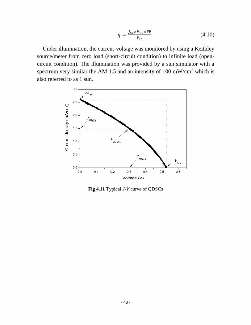
- 43 -
𝜂 =𝐽sc×Voc×FF
Pin (4.10)
Under illumination, the current-voltage was monitored by using a Keithley
source/meter from zero load (short-circuit condition) to infinite load (open-
circuit condition). The illumination was provided by a sun simulator with a
spectrum very similar the AM 1.5 and an intensity of 100 mW/cm2 which is
also referred to as 1 sun.
Fig 4.11 Typical J-V curve of QDSCs

- 44 -

- 45 -
Chapter 5
Results and Discussion
5.1 Study of type-II QDs sensitized solar cells (Papers IV and
VI)
As shown in Fig 5.1, type-II QDs have a special electron-hole pair
separation character, which makes the photoelectron and the photohole
localized on the CB of the shell and on the VB of the core, respectively.54 In
Paper IV, colloidal type-II ZnSe/CdS QDSCs were fabricated and studied.
Two colloidal QDs with different thickness of shell, ZnSe/CdS-1 and
ZnSe/CdS-2, were synthesized from 4.5 nm ZnSe seeds, where ZnSe/CdS-2
has a thicker shell.
Fig. 5.1 Schematic representation of type-II ZnSe/CdS QDSCs. The special charge
separation effect makes the electron located on the CB of the CdS shell and the hole is
located on the VB of the ZnSe core, favoring the electron injection into TiO2. (Paper IV,
Scheme 1)
From the absorption (Paper IV, Fig. 2), we found that the type-II QDs can
effectively broaden the absorption spectrum without a CB decrease that is
usually caused by the decrease of the bandgap. From the time-resolved
transient fluorescence spectra (Paper IV, Fig. 3), the type-II QDs exhibit a
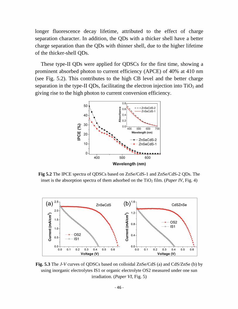
- 46 -
longer fluorescence decay lifetime, attributed to the effect of charge
separation character. In addition, the QDs with a thicker shell have a better
charge separation than the QDs with thinner shell, due to the higher lifetime
of the thicker-shell QDs.
These type-II QDs were applied for QDSCs for the first time, showing a
prominent absorbed photon to current efficiency (APCE) of 40% at 410 nm
(see Fig. 5.2). This contributes to the high CB level and the better charge
separation in the type-II QDs, facilitating the electron injection into TiO2 and
giving rise to the high photon to current conversion efficiency.
Fig 5.2 The IPCE spectra of QDSCs based on ZnSe/CdS-1 and ZnSe/CdS-2 QDs. The
inset is the absorption spectra of them adsorbed on the TiO2 film. (Paper IV, Fig. 4)
Fig. 5.3 The J-V curves of QDSCs based on colloidal ZnSe/CdS (a) and CdS/ZnSe (b) by
using inorganic electrolytes IS1 or organic electrolyte OS2 measured under one sun
irradiation. (Paper VI, Fig. 5)

- 47 -
In Paper VI, two type-II colloidal core/shell ZnSe/CdS and CdS/ZnSe QDs
were synthesized. Obviously, for ZnSe/CdS QDs, ZnSe is the core and CdS
is the shell. In contrast, CdS is the core and ZnSe is the shell in CdS/ZnSe
QDs. The two type of QDs were utilized in QDSCs to study the photovoltaic
effect of the exchange of core and shell materials.
From the J-V curves in Fig. 5.3, the photocurrent of the QDSC based on the
ZnSe/CdS QDs is obviously higher than that of CdS/ZnSe. Similarly, the
IPCE of ZnSe/CdS QDSCs is also higher (Paper VI, Fig. 3). Since these two
QDs adsorbed on TiO2 films exhibit a similar absorption spectrum (Paper VI,
Fig. 4), it can be concluded that the electron injection efficiency of the
ZnSe/CdS QDs is higher than that for the CdS/ZnSe QDs. As noted in the
above discussion of Paper IV, the electrons are localized in the CdS shell for
ZnSe/CdS QDs, leading to facilitate the electron injection. In contrast, for
CdS/ZnSe QDs, the electrons are largely confined in the core, giving a low
electron extraction efficiency.
5.2 Study of quantum rod-sensitized solar cells (Paper V)
Fig 5.4 Schematic drawing of the electron transfer process for QDs and QRs. QRs with a
two-dimensional confinement facilitate the carrier transport, thus improving the electron
injection efficiency.
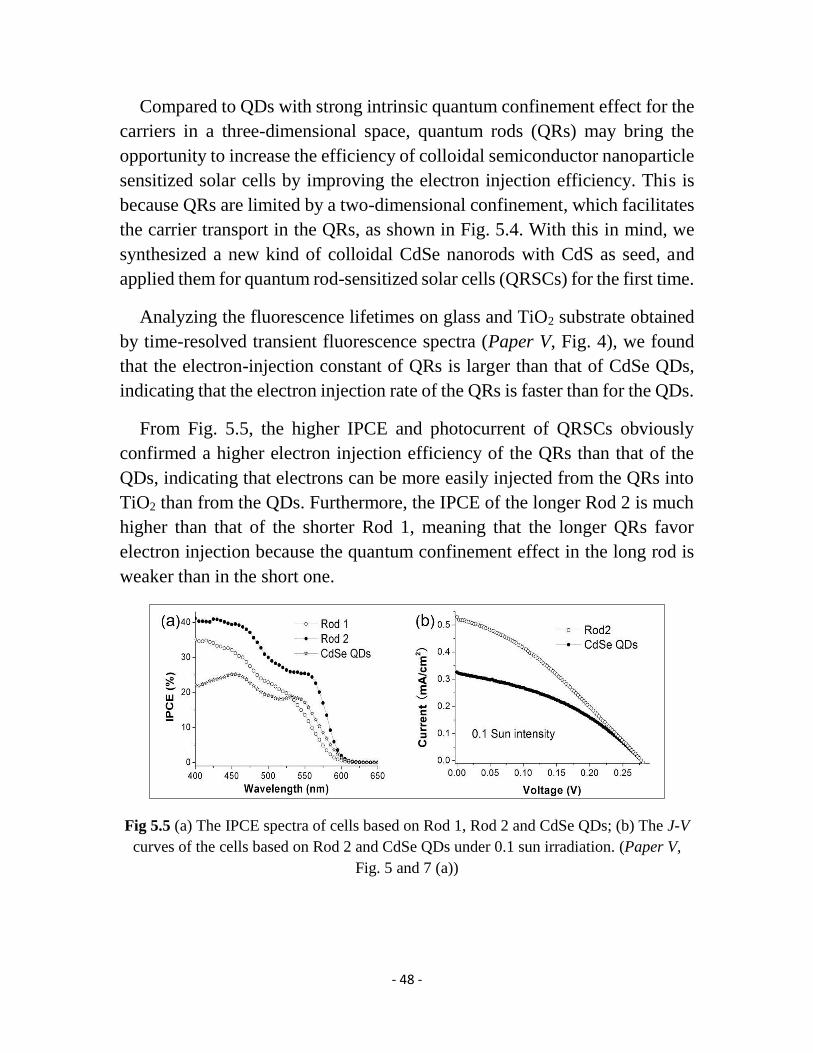
- 48 -
Compared to QDs with strong intrinsic quantum confinement effect for the
carriers in a three-dimensional space, quantum rods (QRs) may bring the
opportunity to increase the efficiency of colloidal semiconductor nanoparticle
sensitized solar cells by improving the electron injection efficiency. This is
because QRs are limited by a two-dimensional confinement, which facilitates
the carrier transport in the QRs, as shown in Fig. 5.4. With this in mind, we
synthesized a new kind of colloidal CdSe nanorods with CdS as seed, and
applied them for quantum rod-sensitized solar cells (QRSCs) for the first time.
Analyzing the fluorescence lifetimes on glass and TiO2 substrate obtained
by time-resolved transient fluorescence spectra (Paper V, Fig. 4), we found
that the electron-injection constant of QRs is larger than that of CdSe QDs,
indicating that the electron injection rate of the QRs is faster than for the QDs.
From Fig. 5.5, the higher IPCE and photocurrent of QRSCs obviously
confirmed a higher electron injection efficiency of the QRs than that of the
QDs, indicating that electrons can be more easily injected from the QRs into
TiO2 than from the QDs. Furthermore, the IPCE of the longer Rod 2 is much
higher than that of the shorter Rod 1, meaning that the longer QRs favor
electron injection because the quantum confinement effect in the long rod is
weaker than in the short one.
Fig 5.5 (a) The IPCE spectra of cells based on Rod 1, Rod 2 and CdSe QDs; (b) The J-V
curves of the cells based on Rod 2 and CdSe QDs under 0.1 sun irradiation. (Paper V,
Fig. 5 and 7 (a))

- 49 -
5.3 Study of alloy PbxCd1-xS QDSCs (Paper III)
PbS QDs with a narrow bandgap show a low efficiency in QDSCs due to
the low CB level, which leads to heavy charge recombination. CdS QDSCs
exhibit a high electron injection efficiency due to the high CB level of the CdS
QDs, but are limited by the narrow light-harvesting region due to the wide
bandgap of CdS. Therefore, in this work, the ternary-alloy PbxCd1-xS QDs
were investigated as photosensitizer for the QDSCs. We prepared three kinds
of PbxCd1-xS QDs by the process of SILAR (see section 4.4.2.1) and studied
the effect of the ratio of Pb : Cd of PbxCd1-xS on the photovoltaic performance
of the PbxCd1-xS QDSCs.
Fig. 5.6 (a) IPCE spectra and (b) J-V curves of QDSCs employing CdS, PbS and PbCdS-
1 with 3 SILAR cycles as photosensitizers. 3C means 3 SILAR cycles. (Paper III, Fig. 2
and 3)
Firstly we compared 3-SILAR-cycle PbCdS-1 (Pb0.54Cd0.46S) QDs with the
corresponding PbS and CdS QDs. From the absorption spectra (Paper III, Fig.
1), it can be found that the PbCdS-1 QDs present an excellent absorption
ability similar to that of the PbS QDs. A comparison of the photovoltaic
performance shown in Fig. 5.6 indicates that the solar cell based on PbCdS-1
QDs exhibits a significantly higher photocurrent. This is attributed to that the
absorption range is broader than that of the CdS QDs and that the electron
injection efficiency is higher than that of the PbS QDs, resulting from the
narrow bandgap and the high CB energy level. This result indicates that the

- 50 -
PbxCd1-xS QDs may possibly overcome the shortcomings of the CdS and PbS
QDSCs.
Fig. 5.7 (a) IPCE spectra and (b) J-V curves of QDSCs employing PbCdS-1 (7 SILAR
cycles), PbCdS-2 (7 SILAR cycles) and PbCd-3 (9 SILAR cycles). (Paper III, Fig. 6)
To study the effect of the proportions of Pb and Cd in the PbxCd1-xS QDs,
the PbCdS-2 (Pb0.31Cd0.69S) and PbCdS-3 (Pb0.24Cd0.76S) were also prepared.
The photovoltaic parameters of these three kinds of PbxCd1-xS QDSCs were
optimized by adjusting the number of SILAR cycles (Paper III, Fig. S1, Tab.
S3 and Fig. 5). In order to better understand the effect, the optimized
performance of the solar cells based on the 7-cycle PbCdS-1, 7-cycle PbCdS-
2 and 9-cycle PbCdS-3 QDs are extracted and illustrated in Figure 5.7. There
some characteristic trends are unveiled. The photocurrent trend is as followed:
PbCdS-1 > PbCdS-2 > PbCdS-3, which is mainly determined by their light-
harvesting ability, leading to the highest photocurrent of up to 20 mA/cm2.
However, the photovoltage follows the reverse trend. This is probably due to
the narrowing of the bandgap of PbxCd1-xS QDs caused by the increase of the
proportion of Pb. As a result, the PbCdS-2 QDSCs present a highest efficiency
of 2.8% with the moderate photocurrent of 15.8 mA/cm2 and voltage of 0.4 V.
It can be concluded that it is quite important to control the ratio of Pb : Cd of
the PbxCd1-xS QDs in order to improve the photovoltaic performance of alloy
PbxCd1-xS QDSCs.
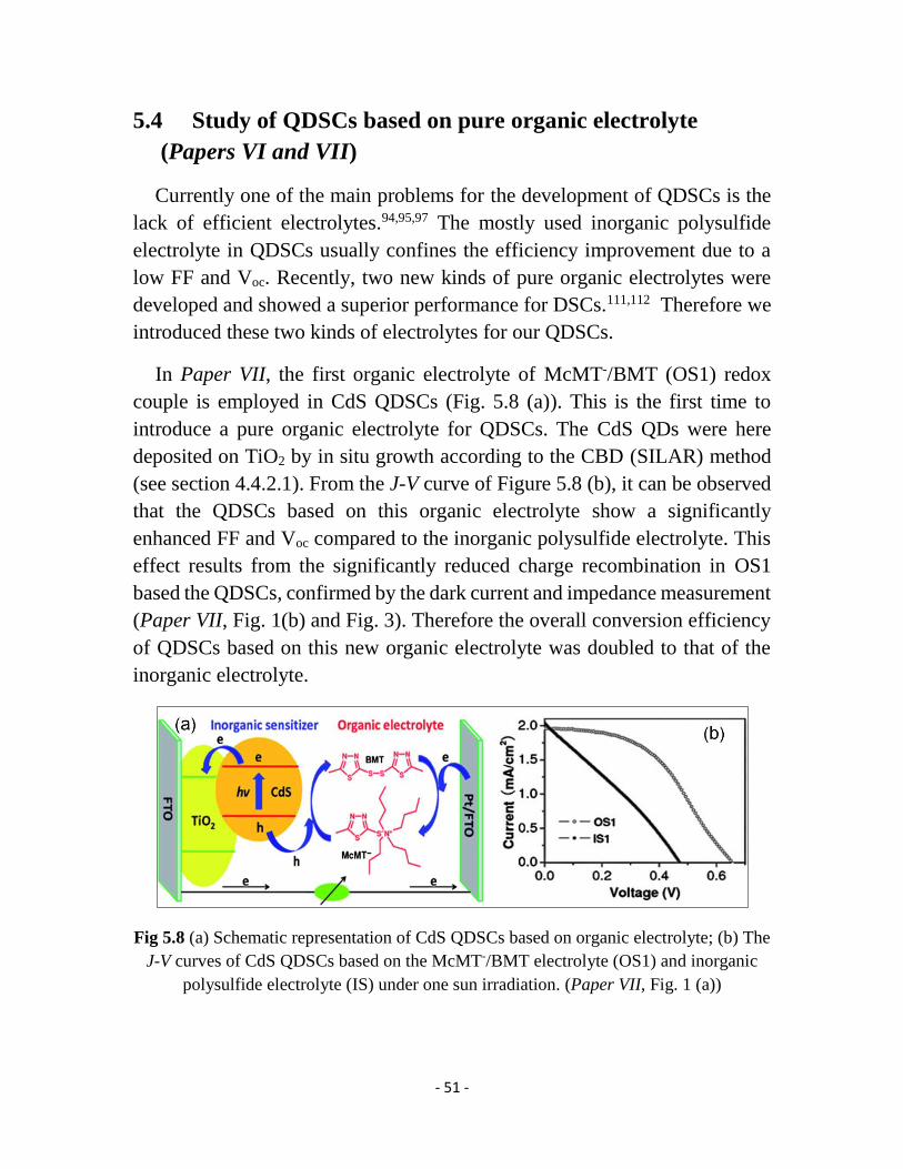
- 51 -
5.4 Study of QDSCs based on pure organic electrolyte
(Papers VI and VII)
Currently one of the main problems for the development of QDSCs is the
lack of efficient electrolytes.94,95,97 The mostly used inorganic polysulfide
electrolyte in QDSCs usually confines the efficiency improvement due to a
low FF and Voc. Recently, two new kinds of pure organic electrolytes were
developed and showed a superior performance for DSCs.111,112 Therefore we
introduced these two kinds of electrolytes for our QDSCs.
In Paper VII, the first organic electrolyte of McMT-/BMT (OS1) redox
couple is employed in CdS QDSCs (Fig. 5.8 (a)). This is the first time to
introduce a pure organic electrolyte for QDSCs. The CdS QDs were here
deposited on TiO2 by in situ growth according to the CBD (SILAR) method
(see section 4.4.2.1). From the J-V curve of Figure 5.8 (b), it can be observed
that the QDSCs based on this organic electrolyte show a significantly
enhanced FF and Voc compared to the inorganic polysulfide electrolyte. This
effect results from the significantly reduced charge recombination in OS1
based the QDSCs, confirmed by the dark current and impedance measurement
(Paper VII, Fig. 1(b) and Fig. 3). Therefore the overall conversion efficiency
of QDSCs based on this new organic electrolyte was doubled to that of the
inorganic electrolyte.
Fig 5.8 (a) Schematic representation of CdS QDSCs based on organic electrolyte; (b) The
J-V curves of CdS QDSCs based on the McMT-/BMT electrolyte (OS1) and inorganic
polysulfide electrolyte (IS) under one sun irradiation. (Paper VII, Fig. 1 (a))
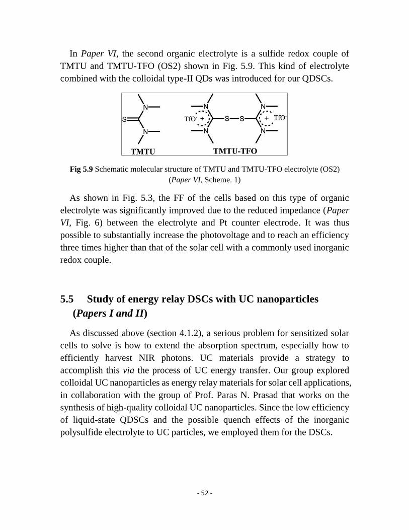
- 52 -
In Paper VI, the second organic electrolyte is a sulfide redox couple of
TMTU and TMTU-TFO (OS2) shown in Fig. 5.9. This kind of electrolyte
combined with the colloidal type-II QDs was introduced for our QDSCs.
Fig 5.9 Schematic molecular structure of TMTU and TMTU-TFO electrolyte (OS2)
(Paper VI, Scheme. 1)
As shown in Fig. 5.3, the FF of the cells based on this type of organic
electrolyte was significantly improved due to the reduced impedance (Paper
VI, Fig. 6) between the electrolyte and Pt counter electrode. It was thus
possible to substantially increase the photovoltage and to reach an efficiency
three times higher than that of the solar cell with a commonly used inorganic
redox couple.
5.5 Study of energy relay DSCs with UC nanoparticles
(Papers I and II)
As discussed above (section 4.1.2), a serious problem for sensitized solar
cells to solve is how to extend the absorption spectrum, especially how to
efficiently harvest NIR photons. UC materials provide a strategy to
accomplish this via the process of UC energy transfer. Our group explored
colloidal UC nanoparticles as energy relay materials for solar cell applications,
in collaboration with the group of Prof. Paras N. Prasad that works on the
synthesis of high-quality colloidal UC nanoparticles. Since the low efficiency
of liquid-state QDSCs and the possible quench effects of the inorganic
polysulfide electrolyte to UC particles, we employed them for the DSCs.

- 53 -
Fig. 5.10 The J–V curves of DSCs (a) with and (b) without NEY-1 UC nanoparticles as
energy relay material under the illumination of a 980 nm laser with increasing incident
power. (c) The J–V curves of NEY-2 nanoparticles-based cell, and the control cell
without Z907 dye. (Paper I, Fig. 3)
In Paper I, we introduced two kinds of NaYF4:Er3+ 2%/Yb3+ 20% UC
nanoparticles, NEY-1and NEY-2, that co-dope 2% Er3+ and 20% Yb3+ into
NaYF4 as host and that can generate UC emission under a 980 nm irradiation.
NEY-1 with a diameter of 20 nm gives a 0.1% UC quantum yield. NEY-2
with a diameter of 7 nm gives a 0.001% UC quantum yield. From the PL
spectra of the UC nanoparticle solution with and without organic dye (Paper
I, Fig. 2), we found that the PL intensity of the nanoparticle solution in the
visible region decreases significantly when the solution is mixed with organic
dye. This result infers that there is a possible energy transfer from the UC
nanoparticles to the organic dye.
The photovoltaic performance of the UC nanoparticle based DSCs were
measured under 980 nm laser irradiation with different incident intensity (see
Fig. 5.10). It can be seen that the photocurrent of the solar cell with the
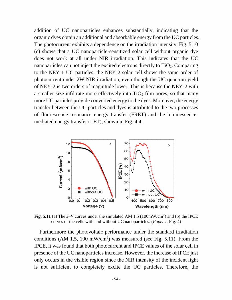
- 54 -
addition of UC nanoparticles enhances substantially, indicating that the
organic dyes obtain an additional and absorbable energy from the UC particles.
The photocurrent exhibits a dependence on the irradiation intensity. Fig. 5.10
(c) shows that a UC nanoparticle-sensitized solar cell without organic dye
does not work at all under NIR irradiation. This indicates that the UC
nanoparticles can not inject the excited electrons directly to TiO2. Comparing
to the NEY-1 UC particles, the NEY-2 solar cell shows the same order of
photocurrent under 2W NIR irradiation, even though the UC quantum yield
of NEY-2 is two orders of magnitude lower. This is because the NEY-2 with
a smaller size infiltrate more effectively into TiO2 film pores, so that many
more UC particles provide converted energy to the dyes. Moreover, the energy
transfer between the UC particles and dyes is attributed to the two processes
of fluorescence resonance energy transfer (FRET) and the luminescence-
mediated energy transfer (LET), shown in Fig. 4.4.
Fig. 5.11 (a) The J–V curves under the simulated AM 1.5 (100mW/cm2) and (b) the IPCE
curves of the cells with and without UC nanoparticles. (Paper I, Fig. 4)
Furthermore the photovoltaic performance under the standard irradiation
conditions (AM 1.5, 100 mW/cm2) was measured (see Fig. 5.11). From the
IPCE, it was found that both photocurrent and IPCE values of the solar cell in
presence of the UC nanoparticles increase. However, the increase of IPCE just
only occurs in the visible region since the NIR intensity of the incident light
is not sufficient to completely excite the UC particles. Therefore, the

- 55 -
enhancement of the photocurrent is attributed to scattering of the light by the
UC particles.
Fig. 5.12 (a) The J-V curves of standard solar cell without UC particles (UCP) (black
line), with the addition of UCP (red line), and a control sample without organic dye
(green line) under the illumination of a 980 nm laser with a power of 2 W. (b) The J-V
curves of the standard solar cell (black line), with the addition of UCP (red line) under
the illumination of a 785 nm laser with a power of 25 mW. (Paper II, Fig. 4 and 5)
In Paper II, novel core-shell-structured β-
NaYbF4:Er3+(2%)/NaYF4:Nd3+(30%) UC nanoparticles were utilized for the
energy relay DSCs. This kind of UC particles (UCPs) can give a UC emission
at around 785 nm irradiation in addition to 980 nm (Paper II, Fig. 1). Similarly,
its PL intensity also decreases remarkably under both wavelength excitations
when adding an organic dye. The diameter of the UCP is around 50 nm, which
is larger than the pore size of the commonly transparent TiO2 film made by
around 20 nm TiO2 nanoparticles. So another type of TiO2 film was used in
this work, where a scattering layer of ~100 nm TiO2 particles was fabricated
onto the transparent layer. The pore size of the scattering layer is big enough
for the UCP to infiltrate. Therefore the adsorbed UCPs are localized in the
scattering layer of the TiO2 film (Paper II, Fig. 3).
The J-V performance is tested under the illumination of 980 and 785 nm,
respectively (see Fig. 5.12). Firstly, we found that the UCP adsorbed solar cell
without organic dye was not working under NIR laser illumination, indicating
there is no electron transfer from the UCP to TiO2. And under 980 nm laser
illumination, the cell without UCP almost does not work at all, showing a
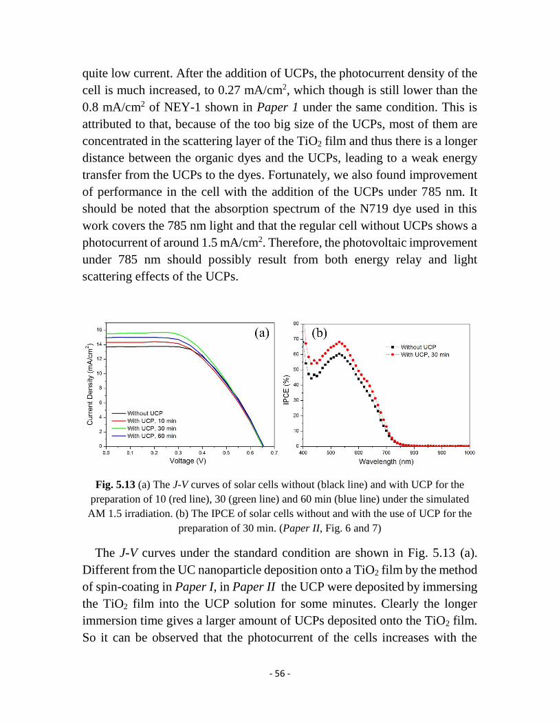
- 56 -
quite low current. After the addition of UCPs, the photocurrent density of the
cell is much increased, to 0.27 mA/cm2, which though is still lower than the
0.8 mA/cm2 of NEY-1 shown in Paper 1 under the same condition. This is
attributed to that, because of the too big size of the UCPs, most of them are
concentrated in the scattering layer of the TiO2 film and thus there is a longer
distance between the organic dyes and the UCPs, leading to a weak energy
transfer from the UCPs to the dyes. Fortunately, we also found improvement
of performance in the cell with the addition of the UCPs under 785 nm. It
should be noted that the absorption spectrum of the N719 dye used in this
work covers the 785 nm light and that the regular cell without UCPs shows a
photocurrent of around 1.5 mA/cm2. Therefore, the photovoltaic improvement
under 785 nm should possibly result from both energy relay and light
scattering effects of the UCPs.
Fig. 5.13 (a) The J-V curves of solar cells without (black line) and with UCP for the
preparation of 10 (red line), 30 (green line) and 60 min (blue line) under the simulated
AM 1.5 irradiation. (b) The IPCE of solar cells without and with the use of UCP for the
preparation of 30 min. (Paper II, Fig. 6 and 7)
The J-V curves under the standard condition are shown in Fig. 5.13 (a).
Different from the UC nanoparticle deposition onto a TiO2 film by the method
of spin-coating in Paper I, in Paper II the UCP were deposited by immersing
the TiO2 film into the UCP solution for some minutes. Clearly the longer
immersion time gives a larger amount of UCPs deposited onto the TiO2 film.
So it can be observed that the photocurrent of the cells increases with the

- 57 -
addition of UCPs. The highest photocurrent is obtained for the cell with UCPs
for 30 min immersion. Compared to the regular cell without UCPs, its current
increases from 13.7 to 15.5 mA/cm2 and as a result the overall efficiency
increases to 5.2% (Paper II, Table 2).When the immersion time is prolonged,
the performance gets worse. As we know the UCP size is much bigger than
the pore size of the transparent layer of the TiO2 film, so too many deposited
UCPs will block the pores at the interface between the transparent layer and
the scattering layer, thereby limiting the electrolyte to reduce the oxidized
dyes. Similarly, the enhancement of the photocurrent and IPCE is mostly
attributed to that the UCP also acts as a scattering material.

- 58 -
- 59 -
Chapter 6
Conclusion and Future Outlook
Conclusion
In Papers IV and VI colloidal type-II quantum dots (QDs) were applied for
sensitized solar cells for the first time. The type-II ZnSe/CdS QDs can
effectively broaden the absorption spectrum, and the separation of electrons
and holes in these QDs can effectively enhance their charge extraction
efficiency. As a result, the type-II QD sensitized solar cells (QDSCs) exhibit
a high photovoltaic performance. Furthermore, comparing the performance of
type-II ZnSe/CdS and CdS/ZnSe QDs proved that the electron distribution in
the QDs is important for the electron injection.
In the study of the quantum rod-sensitized solar cells (QRSCs) (Paper V),
a novel kind of colloidal CdS/CdSe QRs was applied in sensitized solar cell
for the first time. These QRSCs showed a distinctly higher electron injection
efficiency than the corresponding QDSCs. The result demonstrates a new
strategy to increase the electron injection efficiency of nanoparticle sensitized
solar cells by the modification of the shape of the nanoparticles.
In the study of the pure organic electrolytes for QDSCs (Papers VI and VII),
two kinds of such pure organic electrolytes (OS1 and OS2) were successfully
applied for QDSCs, giving much higher conversion efficiency than that of the
solar cell with inorganic electrolyte due to the much increased fill factor and
photovoltage.
In the study of the alloy QDSCs (Paper III), three kinds of ternary-alloy
PbxCd1-xS were utilized as photosensitizers, exhibiting higher photocurrents
compared to the corresponding CdS and PbS QDSCs. In addition, the solar
cells based on the PbxCd1-xS QDs with a higher proportion of Pb present a
larger photocurrent and a lower photovoltage due to the narrower bandgap
and the lower conduction band (CB) energy level. This suggests that a

- 60 -
reasonable ratio of Pb to Cd in the PbxCd1-xS QDs is the key factor for
optimizing the photovoltaic performances of the corresponding QDSCs.
In the study of the energy relay solar cells (Papers I and II), three kinds of
upconversion (UC) nanoparticle were utilized as energy relay materials in the
dye-sensitized solar cells (DSCs), which can efficiently extend the light-
harvesting spectrum to the near-infrared (NIR) region. Under the irradiation
of an NIR laser, such as 980 nm, photocurrents generated by UC nanoparticles
were observed and thus an energy transfer process from the UC nanoparticles
to the organic dye was confirmed. The UC nanoparticles with smaller size
favor the infiltration into the pores of the TiO2 film, leading to a higher energy
relay efficiency. Moreover, in addition to the energy relay material, UC
nanoparticles are also found to serve as a scattering material to improve the
photovoltaic performance of the solar cells. This study shows a strategy to
develop panchromatic DSCs by employing high-quality colloidal UC
nanoparticles.
Future Outlook
Although nanoparticle sensitized solar cells possess an excellent potential
and have shown a fast development in the recent years, the overall efficiency
of QDSCs is still far less than the requirement for large-scale applications.
Many critical challenges need to be met in the future, the most important of
them is to increase the electron transport rate and the light-harvesting ability,
decrease the charge recombination, maintain low toxicity and extend
durability. The photovoltaic performance of solar cells can be improved from
the following points of view:
TiO2 photoelectrode: Compared to the regular photoelectrode with TiO2
spherical nanoparticles, TiO2 nanotubes, nanorods or nanowires have been
confirmed to be efficient structures to improve the electron transport and thus
decrease the charge recombination between TiO2 and QDs or electrolyte.82 In
addition, other materials with similar structures, such as ZnO85 and carbon113,
can be employed.
- 61 -
QDs sensitizer: As extensively discussed in the thesis, the spatial electron
and hole separation of type-II QDs and the reduction of the carrier
confinement dimensions of QRs can enhance the electron injection efficiency.
Further research following this way should be made in order to develop
panchromatic and stable nanoparticles. The high-quality alloy QDs are
worthwhile to focus on in further studies as their optoelectronic performance
can be controlled by adjusting the proportions of the component elements
rather than by changing the QD size. For the consideration of toxicity, low
toxic QDs, such as InP, Ag2S, Sb2S3 and CuInS, should be employed in the
QDSCs. In addition, we can develop more effective passivation materials, like
ZnS, to suppress the recombination between photoelectrode and electrolyte
and increase the chemical stability of the QDSCs.
Electrolyte: Organic electrolytes provide a strategy to develop the
performance of QDSCs by reducing the charge recombination between the
electrolyte and counter electrode. Such electrolytes should be noncorrosive
for QDs. Additionally, low-volatile solvents, ionic liquids or solid-state
electrolytes should be further explored for improving the durability of the
solar cells.
Counter electrode: Although many new materials for use as counter
electrode tested in QDSCs can potentially give an improved performance,
their fill factors (FF) are still lower than the level for the DSCs. Thus, efforts
should be taken to develop more efficient counter electrodes for QDSCs.
UC nanoparticles: UC nanoparticles as energy relay materials were proved
to be an efficient route to utilize NIR light in solar cells. To enhance the
efficiency of the solar cells, the quality of the UC nanoparticles can be further
improved from several aspects, like UC quantum yield, molar extinction
coefficient of the NIR region and particle size.
Taking all together I believe that nanoparticle-sensitized solar cells will
have a promising potential to become the primary choice of solar cells in
terms of efficiency and that they will contribute to the world energy market.
- 62 -
Acknowledgements
I would like to express my sincere gratitude to:
Prof. Hans Ågren, my supervisor, for giving me this opportunity to get my
Doctoral degree, for providing the great experimental conditions, and for
constant encouragement and support during the years.
Associate Prof. Ying Fu, my supervisor in the first two years, for accepting
me as a Ph.D student, for sharing knowledge to me, for being so patient and
encouraging.
Prof. Licheng Sun for the help, support and nice collaboration during the
whole period of my Ph.D study.
Prof Paras N. Prasad (SUNY University at Buffalo, UB) for giving me an
opportunity to study and work in your group for three months. It was an
excellent experience.
Prof. Yi Luo for the warm-hearted help. Associate Prof. Mårten Ahlquist for
nice discussion about the project problems. Associate Prof. Hao Zeng (UB)
for nice discussion.
Dr. Zhijun Ning, my excellent colleague and friend, for sharing the knowledge,
collaboration and support especially during the beginning of my Ph.D. I
learned a lot from you. It was great to work with you. Dr. Guanying Chen
(UB) for the enthusiastic help during my stay at Buffalo and for encouraging
discussions and nice collaboration.
Haining Tian, Lin Li, Jossana Damasco (UB), Hui Xing (UB), Jing Huang,
Tianmu Zhang (UB), Tymish Y. Ohulchanskyy (UB), Peter Hedström and
Haiyan Qin for nice collaboration.
All the members of the groups of Prof Licheng Sun and of Prof Paras N.
Prasad for being so friendly and helpful.

- 63 -
Nina Bauer, Marlene Johnsson and Lotta Rosenfeldt for all help with
administrative things.
Ying Wang, Yong Ma, Quan Miao, Zhihui Chen, Xiangjun Shang, Staffan
Hellstrom, Xifeng Yang, Yongfei Ji, Lun Sun and Wei Hu for taking courses
together and sharing knowledge.
Zhijun Ning, Li Li and Jing Huang for nice working together in the lab.
Xifeng Yang, Lijun Liang and Jing Huang for sharing the office.
All former and present co-workers at the department of theoretical chemistry
& biology for spreading the nice atmosphere.
My friends and family for always being there. Especially, my wife Lin for
every single day.
- 64 -
References
(1) Chapin, D. M.; Fuller, C. S.; Pearson, G. L. J. Appl. Phys. 1954, 25,
676.
(2) O'Regan, B.; Grätzel, M. Nature 1991, 353, 737.
(3) Yella, A.; Lee, H.-W.; Tsao, H. N.; Yi, C.; Chandiran, A. K.;
Nazeeruddin, M. K.; Diau, E. W.-G.; Yeh, C.-Y.; Zakeeruddin, S. M.; Grätzel,
M. Science 2011, 334, 629.
(4) Kinoshita, T.; Dy, J. T.; Uchida, S.; Kubo, T.; Segawa, H. Nat.
Photonics 2013, 7, 535.
(5) Hagfeldt, A.; Boschloo, G.; Sun, L.; Kloo, L.; Pettersson, H. Chem. Rev.
2010, 110, 6595.
(6) Bruchez, M., Jr.; Moronne, M.; Gin, P.; Weiss, S.; Alivisatos, A. P.
Science 1998, 281, 2013.
(7) Medintz, I.; Uyeda, H.; Goldman, E.; Mattoussi, H. Nat. Mater. 2005,
4, 435.
(8) Anikeeva, P. O.; Halpert, J. E.; Bawendi, M. G.; Bulovic, V. Nano Lett.
2009, 9, 2532.
(9) Huynh, W. U.; Dittmer, J. J.; Alivisatos, A. P. Science 2002, 295, 2425.
(10) Mora-Sero, I.; Gimenez, S.; Fabregat-Santiago, F.; Gomez, R.; Shen,
Q.; Toyoda, T.; Bisquert, J. Acc. Chem. Res. 2009, 42, 1848.
(11) Lee, H.; Leventis, H. C.; Moon, S.-J.; Chen, P.; Ito, S.; Haque, S. A.;
Torres, T.; Nueesch, F.; Geiger, T.; Zakeeruddin, S. M.; Grätzel, M.;
Nazeeruddin, M. K. Adv. Funct. Mater. 2009, 19, 2735.
(12) Lee, Y.-L.; Lo, Y.-S. Adv. Funct. Mater. 2009, 19, 604.
(13) Yu, X.-Y.; Liao, J.-Y.; Qiu, K.-Q.; Kuang, D.-B.; Su, C.-Y. ACS Nano
2011, 5, 9494.
(14) Randy, J. E.; Matthew, C. B.; Justin, C. J.; Pingrong, Y.; Olga, I. M.;
Arthur, J. N.; Andrew, S.; Alexander, L. E. Nano Lett. 2005, 5, 865.
(15) Chang, J. A.; Rhee, J. H.; Im, S. H.; Lee, Y. H.; Kim, H.-j.; Seok, S. I.;
Nazeeruddin, M. K.; Grätzel, M. Nano Lett. 2010, 10, 2609.
(16) Zhang, Q.; Guo, X.; Huang, X.; Huang, S.; Li, D.; Luo, Y.; Shen, Q.;
Toyoda, T.; Meng, Q. Phys. Chem. Chem. Phys. 2011, 13, 4659.
(17) Salerno, E. AWEA Director of Industry and Data Analysis, as quoted
in Shahan, Z, 2011.
(18) Grätzel, M. Nature 2001, 414, 338.
(19) Kopp, G.; Lean, J. L. Geophysical Research Letters 2011, 38.
(20) Wurfel, P. The Physics of Solar Cells; Wiley-VCH, 2005.
- 65 -
(21) Martin A, G. Physica E 2002, 14, 11.
(22) Nozik, A.; Beard, M.; Luther, J.; Law, M. Chem. Rev. 2010, 110, 6873.
(23) Rossetti, R.; Brus, L. J. Phys. Chem. 1982, 86, 4470.
(24) Yu, W. W.; Peng, X. Angew. Chem., Int. Ed. 2002, 41, 2368.
(25) Qu, L.; Peng, X. J. Am. Chem. Soc. 2002, 124, 2049.
(26) Lee, H. J.; Yum, J. H.; Leventis, H. C.; Zakeeruddin, S. M.; Haque, S.
A.; Chen, P.; Seok, S. I.; Gräzel, M.; Nazeeruddin, M. K. Journal of Physical
Chemistry C 2008, 112, 11600.
(27) Gao, M. Y.; Kirstein, S.; Mohwald, H.; Rogach, A. L.; Kornowski, A.;
Eychmuller, A.; Weller, H. J. Phys. Chem. B 1998, 102, 8360.
(28) Gaponik, N.; Talapin, D. V.; Rogach, A. L.; Hoppe, K.; Shevchenko,
E. V.; Kornowski, A.; Eychmuller, A.; Weller, H. J. Phys. Chem. B 2002, 106,
7177.
(29) Hines, M. A.; Guyot-Sionnest, P. J. Phys. Chem. B 1998, 102, 3655.
(30) Xu, S.; Kumar, S.; Nann, T. J. Am. Chem. Soc. 2006, 128, 1054.
(31) Battaglia, D.; Peng, X. G. Nano Lett. 2002, 2, 1027.
(32) Xie, R.; Peng, X. Angew. Chem., Int. Ed. 2008, 47, 7677.
(33) Tanaka, S.; Iwai, S.; Aoyagi, Y. Appl. Phys. Lett. 1996, 69, 4096.
(34) Dasgupta, N. P.; Jung, H. J.; Trejo, O.; McDowell, M. T.; Hryciw, A.;
Brongersma, M.; Sinclair, R.; Prinz, F. B. Nano Lett. 2011, 11, 934.
(35) Murphy, J. E.; Beard, M. C.; Nozik, A. J. J. Phys. Chem. B 2006, 110,
25455.
(36) Niquet, Y. M.; Allan, G.; Delerue, C.; Lannoo, M. Appl. Phys. Lett.
2000, 77, 1182.
(37) Littau, K. A.; Szajowski, P. J.; Muller, A. J.; Kortan, A. R.; Brus, L. E.
J. Phys. Chem. 1993, 97, 1224.
(38) Dabbousi, B. O.; Rodriguez-Viejo, J.; Mikulec, F. V.; Heine, J. R.;
Mattoussi, H.; Ober, R.; Jensen, K. F.; Bawendi, M. G. J. Phys. Chem. B 1997,
101, 9463.
(39) Xu, S.; Ziegler, J.; Nann, T. J. Mater. Chem. 2008, 18, 2653.
(40) Xie, R.; Battaglia, D.; Peng, X. J. Am. Chem. Soc. 2007, 129, 15432.
(41) Manna, L.; Scher, E. C.; Li, L.-S.; Alivisatos, A. P. J. Am. Chem. Soc.
2002, 124, 7136.
(42) Xie, R.; Kolb, U.; Li, J.; Basché, T.; Mews, A. J. Am. Chem. Soc. 2005,
127, 7480.
(43) Kim, S.; Fisher, B.; Eisler, H.-J.; Bawendi, M. J. Am. Chem. Soc. 2003,
125, 11466.
(44) Nemchinov, A.; Kirsanova, M.; Hewa-Kasakarage, N. N.; Zamkov, M.
J. Phys. Chem. C 2008, 112, 9301.
- 66 -
(45) Zhong, X.; Han, M.; Dong, Z.; White, T. J.; Knoll, W. J. Am. Chem.
Soc. 2003, 125, 8589.
(46) Smith, A.; Nie, S. J. Am. Chem. Soc. 2011, 133, 24.
(47) Grabolle, M.; Spieles, M.; Lesnyak, V.; Gaponik, N.; Eychmuller, A.;
Resch-Genger, U. Anal. Chem. 2009, 81, 6285.
(48) Yu, W. W.; Qu, L.; Guo, W.; Peng, X. Chem. Mater. 2003, 15, 2854.
(49) Klimov, V. I. Annu. Rev. Phys. Chem. 2007, 58, 635.
(50) Klimov, V. I.; Mikhailovsky, A. A.; McBranch, D. W.; Leatherdale, C.
A.; Bawendi, M. G. Science 2000, 287, 1011.
(51) Trinh, M. T.; Houtepen, A. J.; Schins, J. M.; Hanrath, T.; Piris, J.;
Knulst, W.; Goossens, A. P. L. M.; Siebbeles, L. D. A. Nano Lett. 2008, 8,
1713.
(52) Fisher, B.; Caruge, J. M.; Zehnder, D.; Bawendi, M. Phys. Rev. Lett.
2005, 94, 087403.
(53) Sambur, J. B.; Novet, T.; Parkinson, B. A. Science 2010, 330, 63.
(54) de Mello Donega, C. Chem. Soc. Rev. 2011, 40, 1512.
(55) Reiss, P.; Protiere, M.; Li, L. Small 2009, 5, 154.
(56) Smith, A. M.; Nie, S. Acc. Chem. Res. 2010, 43, 190.
(57) Kan, S.; Mokari, T.; Rothenberg, E.; Banin, U. Nat. Mater. 2003, 2,
155.
(58) Costi, R.; Saunders, A. E.; Banin, U. Angew. Chem., Int. Ed. 2010, 49,
4878.
(59) Liang, H.-W.; Liu, S.; Yu, S.-H. Adv. Mater. 2010, 22, 3925.
(60) Wang, F.; Liu, X. Chem. Soc. Rev. 2009, 38, 976.
(61) Robel, I.; Subramanian, V.; Kuno, M.; Kamat, P. V. J. Am. Chem. Soc.
2006, 128, 2385.
(62) Zhang, H.; Cheng, K.; Hou, Y. M.; Fang, Z.; Pan, Z. X.; Wu, W. J.;
Hua, J. L.; Zhong, X. H. Chem. Commun. 2012, 48, 11235.
(63) Hossain, M. A.; Jennings, J. R.; Shen, C.; Pan, J. H.; Koh, Z. Y.;
Mathews, N.; Wang, Q. J. Mater. Chem. 2012, 22, 16235.
(64) Santra, P. K.; Kamat, P. V. J Am Chem Soc 2012, 134, 2508.
(65) Lee, J. W.; Son, D. Y.; Ahn, T. K.; Shin, H. W.; Kim, I. Y.; Hwang, S.
J.; Ko, M. J.; Sul, S.; Han, H.; Park, N. G. Scientific reports 2013, 3, 1050.
(66) Pan, Z.; Zhang, H.; Cheng, K.; Hou, Y.; Hua, J.; Zhong, X. ACS Nano
2012, 6, 3982.
(67) Santra, P. K.; Kamat, P. V. J. Am. Chem. Soc. 2013, 135, 877.
(68) Pan, Z.; Zhao, K.; Wang, J.; Zhang, H.; Feng, Y.; Zhong, X. ACS Nano
2013, 7, 5215.
(69) Bach, U.; Lupo, D.; Comte, P.; Moser, J. E.; Weissortel, F.; Salbeck, J.;
Spreitzer, H.; Gratzel, M. Nature (London) 1998, 395, 583.

- 67 -
(70) Chung, I.; Lee, B.; He, J.; Chang, R. P.; Kanatzidis, M. G. Nature 2012,
485, 486.
(71) Im, S. H.; Lim, C. S.; Chang, J. A.; Lee, Y. H.; Maiti, N.; Kim, H. J.;
Nazeeruddin, M. K.; Gratzel, M.; Seok, S. I. Nano Lett. 2011, 11, 4789.
(72) Chang, J. A.; Im, S. H.; Lee, Y. H.; Kim, H. J.; Lim, C. S.; Heo, J. H.;
Seok, S. I. Nano Lett. 2012, 12, 1863.
(73) Kim, H. S.; Lee, C. R.; Im, J. H.; Lee, K. B.; Moehl, T.; Marchioro, A.;
Moon, S. J.; Humphry-Baker, R.; Yum, J. H.; Moser, J. E.; Gratzel, M.; Park,
N. G. Scientific reports 2012, 2, 591.
(74) Lee, M. M.; Teuscher, J.; Miyasaka, T.; Murakami, T. N.; Snaith, H. J.
Science 2012, 338, 643.
(75) Burschka, J.; Pellet, N.; Moon, S. J.; Humphry-Baker, R.; Gao, P.;
Nazeeruddin, M. K.; Gratzel, M. Nature 2013, 499, 316.
(76) Ning, Z.; Fu, Y.; Tian, H. Energy Environ. Sci. 2010, 3, 1170.
(77) Hardin, B. E.; Hoke, E. T.; Armstrong, P. B.; Yum, J.-H.; Comte, P.;
Torres, T.; Fréchet, J. M. J.; Nazeeruddin, M. K.; Grätzel, M.; McGehee, M.
D. Nat. Photonics 2009, 3, 406.
(78) Shan, G. B.; Demopoulos, G. P. Adv. Mater. 2010, 22, 4373.
(79) Liang, L.; Liu, Y.; Bu, C.; Guo, K.; Sun, W.; Huang, N.; Peng, T.; Sebo,
B.; Pan, M.; Liu, W.; Guo, S.; Zhao, X. Z. Adv. Mater. 2013, 25, 2174.
(80) Chang, J.; Ning, Y.; Wu, S.; Niu, W.; Zhang, S. Adv. Funct. Mater.
2013, n/a.
(81) Yang, Z.; Chen, C.-Y.; Roy, P.; Chang, H.-T. Chem. Commun. 2011,
47, 9561.
(82) Kongkanand, A.; Tvrdy, K.; Takechi, K.; Kuno, M.; Kamat, P. V. J.
Am. Chem. Soc. 2008, 130, 4007.
(83) Shah, A.; Torres, P.; Tscharner, R.; Wyrsch, N.; Keppner, H. Science
1999, 285, 692.
(84) Kamat, P. V.; Tvrdy, K.; Baker, D. R.; Radich, J. G. Chem. Rev. 2010,
110, 6664.
(85) Kuo, K.-T.; Liu, D.-M.; Chen, S.-Y.; Lin, C.-C. J. Mater. Chem. 2009,
19, 6780.
(86) Greene, L. E.; Law, M.; Tan, D. H.; Montano, M.; Goldberger, J.;
Somorjai, G.; Yang, P. Nano Lett. 2005, 5, 1231.
(87) Jia, H.; Xu, H.; Hu, Y.; Tang, Y.; Zhang, L. Electrochem. Commun.
2007, 9, 354.
(88) Lévy-Clément, C.; Tena-Zaera, R.; Ryan, M. A.; Katty, A.; Hodes, G.
Adv. Mater. 2005, 17, 1512.
(89) Gao, X.-F.; Li, H.-B.; Sun, W.-T.; Chen, Q.; Tang, F.-Q.; Peng, L.-M.
J. Phys. Chem. C 2009, 113, 7531.
- 68 -
(90) Peter, L. M.; Wijayantha, K. G. U.; Riley, D. J.; Waggett, J. P. J. Phys.
Chem. B 2003, 107, 8378.
(91) Tubtimtae, A.; Wu, K.-L.; Tung, H.-Y.; Lee, M.-W.; Wang, G. J.
Electrochem. Commun. 2010, 12, 1158.
(92) Zaban, A.; Micic, O. I.; Gregg, B. A.; Nozik, A. J. Langmuir 1998, 14,
3153.
(93) Schaller, R. D.; Klimov, V. I. Phys. Rev. Lett. 2004, 92, 186601.
(94) Sambur, J. B.; Parkinson, B. A. J. Am. Chem. Soc. 2010, 132, 2130.
(95) Mora-Sero, I.; Bisquert, J. J. Phys. Chem. Lett. 2010, 1, 3046.
(96) Lee, W.; Min, S. K.; Dhas, V.; Ogale, S. B.; Han, S. H. Electrochem.
Commun. 2009, 11, 103.
(97) Tachibana, Y.; Akiyama, H. Y.; Ohtsuka, Y.; Torimoto, T.; Kuwabata,
S. Chem. Lett. 2007, 36, 88.
(98) Boschloo, G.; Hagfeldt, A. Acc. Chem. Res. 2009, 42, 1819.
(99) Lee, H. J.; Yum, J.-H.; Leventis, H. C.; Zakeeruddin, S. M.; Haque, S.
A.; Chen, P.; Seok, S. I.; Gratzel, M.; Nazeeruddin, M. K. J. Phys. Chem. C
2008, 112, 11600.
(100) Lee, H. J.; Wang, M.; Chen, P.; Gamelin, D. R.; Zakeeruddin, S. M.;
Grätzel, M.; Nazeeruddin, M. K. Nano Lett. 2009, 9, 4221.
(101) Gimenez, S.; Mora-Sero, I.; Macor, L.; Guijarro, N.; Lana-Villarreal,
T.; Gomez, R.; Diguna, L. J.; Shen, Q.; Toyoda, T.; Bisquert, J.
Nanotechnology 2009, 20, 295204.
(102) Yang, Z.; Chen, C. Y.; Liu, C. W.; Chang, H. T. Chem. Commun. 2010,
46, 5485.
(103) Zhang, Q. X.; Zhang, Y. D.; Huang, S. Q.; Huang, X. M.; Luo, Y. H.;
Meng, Q. B.; Li, D. M. Electrochem. Commun. 2010, 12, 327.
(104) Murray, C. B.; Norris, D. J.; Bawendi, M. G. J. Am. Chem. Soc. 1993,
115, 8706.
(105) Peng, Z. A.; Peng, X. G. J. Am. Chem. Soc. 2001, 123, 183.
(106) Fan, S.-Q.; Kim, D.; Kim, J.-J.; Jung, D. W.; Kang, S. O.; Ko, J.
Electrochem. Commun. 2009, 11, 1337.
(107) Shen, Q.; Kobayashi, J.; Diguna, L. J.; Toyoda, T. J. Appl. Phys. 2008,
103, 084304.
(108) Ning, Z.; Tian, H.; Qin, H.; Zhang, Q.; Ågren, H.; Sun, L.; Fu, Y. J.
Phys. Chem. C 2010, 114, 15184.
(109) Mora-Sero, I.; Gimenez, S.; Moehl, T.; Fabregat-Santiago, F.; Lana-
Villareal, T.; Gomez, R.; Bisquert, J. Nanotechnology 2008, 19, 424007.
(110) Grätzel, M. Acc. Chem. Res. 2009, 42, 1788.
(111) Tian, H.; Jiang, X.; Yu, Z.; Kloo, L.; Hagfeldt, A.; Sun, L. Angew.
Chem., Int. Ed. 2010, 49, 7328.

- 69 -
(112) Li, D. M.; Li, H.; Luo, Y. H.; Li, K. X.; Meng, Q. B.; Armand, M.;
Chen, L. Q. Adv. Funct. Mater. 2010, 20, 3358.
(113) Farrow, B.; Kamat, P. V. J. Am. Chem. Soc. 2009, 131, 11124.

- 70 -