Embed Size (px)
Citation preview
This is an electronic reprint of the original article.This reprint may differ from the original in pagination and typographic detail.
Powered by TCPDF (www.tcpdf.org)
This material is protected by copyright and other intellectual property rights, and duplication or sale of all or part of any of the repository collections is not permitted, except that material may be duplicated by you for your research use or educational purposes in electronic or print form. You must obtain permission for any other use. Electronic or print copies may not be offered, whether for sale or otherwise to anyone who is not an authorised user.
Hashmi, Ghufran; Özkan, Merve; Halme, Janne; Zakeeruddin, Shaik Mohammed; Paltakari,Jouni; Grätzel, Michael; Lund, PeterDye-sensitized solar cells with inkjet-printed dyes
Published in:ENERGY AND ENVIRONMENTAL SCIENCE
DOI:10.1039/c6ee00826g
Published: 01/07/2016
Document VersionPublisher's PDF, also known as Version of record
Please cite the original version:Hashmi, S. G., Özkan, M., Halme, J., Zakeeruddin, S. M., Paltakari, J., Grätzel, M., & Lund, P. D. (2016). Dye-sensitized solar cells with inkjet-printed dyes. ENERGY AND ENVIRONMENTAL SCIENCE, 9(7), 2453-2462.DOI: 10.1039/c6ee00826g
This journal is©The Royal Society of Chemistry 2016 Energy Environ. Sci., 2016, 9, 2453--2462 | 2453
Cite this: Energy Environ. Sci.,
2016, 9, 2453
Dye-sensitized solar cells with inkjet-printed dyes†
Syed Ghufran Hashmi,a Merve Ozkan,b Janne Halme,*a Shaik Mohammed Zakeeruddin,c
Jouni Paltakari,b Michael Gratzelc and Peter D. Lunda
The slow process in which the light absorbing dye molecules are adsorbed from solution on the nano-
crystalline TiO2 photoelectrode film has been a handicap to the fast and cost-effective fabrication of
dye-sensitized solar cells (DSSCs) using printing techniques. Here, we report a versatile dye sensitization
process, achieved by inkjet printing a concentrated dye solution over the TiO2 film, which produces
solar cells with equal performance and stability as obtained using the popular dye drop casting method.
In addition to allowing precise control of dye loading required for dispensing just the right amount of
dye to achieve uniform and full coloration of the TiO2 films without any need for washing off the excess
dye, inkjet printing also makes it possible to freely adjust the amount and position of the dye to create
DSSCs with tailored transparency, color density gradients, and patterns of one or more dyes on the
same electrode. The method was confirmed to be applicable also for non-transparent, high-efficiency
DSSC designs that employ a light scattering layer. The inkjet-dyed DSSCs exhibited high stability,
retaining almost 100% of their conversion efficiency (Z = 6.4 � 0.2%) and short circuit current density
(JSC = 14.2 � 0.6 mA cm�2) when subjected to a 1000 h accelerated aging test under 1 Sun illumination
at 35 1C, followed by additional 1154 hours under 0.5 Sun at 60 1C. These results overcome one of the
main hurdles in realizing fully printed DSSCs and open opportunities for entirely new DSSC designs.
Broader contextDye-sensitized solar cells (DSSCs) can be possibly produced at low cost using high throughput methods such as screen or inkjet printing, but to do so requiresre-designing some of their conventional fabrication steps. One of them is the step where the light absorbing dyes are attached to the nanocrystalline TiO2
photoelectrode. This is normally done on the laboratory scale by slowly soaking the TiO2 film in a dye solution. Although methods exist to speed up the processfrom hours to minutes, it could be even quicker and consume less materials, if the dye could be simply printed on the TiO2 film. We report here for the firsttime that this can in fact be done using inkjet printing, which at the same time brings about additional benefits. Inkjet dyeing not only simplifies the overallfabrication and consumes less solvents, but also opens new opportunities for creating multi-coloured solar cells with tailored transparency and decorativedesigns, which can be important attributes for the commercialization of DSSCs.
1. Introduction
Dye sensitized solar cells (DSSCs) have been considered as apromising photovoltaic technology because they can be producedfrom abundantly available raw materials on various substratesusing fast printing processes,1–3 and have intrinsic features, suchas semi-transparency and color,4,5 as well as good operation atlow light intensity,6 which offer interesting product opportunities
for building integrated photovoltaics and energy harvestingfor low power wireless electronics.5,7–9 However, in order tomanufacture them at high speed and using the roll-to-rollprinting methods, some of their conventional fabrication stepshave to be re-designed.1
In the conventional fabrication method of dye-sensitized solarcells, a monolayer of dye molecules is attached to the nanocrystal-line TiO2 photoelectrode film by soaking it for 16–24 hours in a dyebath containing the sensitizer molecules, usually the rutheniumcomplex N719, which is followed by rinsing off the excess dye.10,11
Although suitable for small-scale experiments, and thereforepopular in the research labs, this process is too slow for highthrough-put manufacturing, which should ideally consist of onlyfast, additive material printing and deposition steps, each com-pleted in the time frame of seconds to minutes, as already demon-strated for roll-to-roll fabrication of organic solar cells.12–17
a Department of Applied Physics, Aalto University School of Science,
P.O. BOX 15100, FI-00076 Aalto (Espoo), Finland. E-mail: [email protected] Department of Forest Products Technology, Aalto University School of Chemical
Technology, P.O. BOX 15100, FI-00076 Aalto (Espoo), Finlandc Laboratory of Photonics and Interfaces, Ecole Polytechnique Federale de Lausanne
(EPFL), CH G1 551, Station 6, CH-1015 Lausanne, Switzerland
† Electronic supplementary information (ESI) available. See DOI: 10.1039/c6ee00826g
Received 18th March 2016,Accepted 9th June 2016
DOI: 10.1039/c6ee00826g
www.rsc.org/ees
Energy &EnvironmentalScience
PAPER
Ope
n A
cces
s A
rtic
le. P
ublis
hed
on 0
9 Ju
ne 2
016.
Dow
nloa
ded
on 0
9/03
/201
7 14
:41:
18.
Thi
s ar
ticle
is li
cens
ed u
nder
a C
reat
ive
Com
mon
s A
ttrib
utio
n 3.
0 U
npor
ted
Lic
ence
.
View Article OnlineView Journal | View Issue
2454 | Energy Environ. Sci., 2016, 9, 2453--2462 This journal is©The Royal Society of Chemistry 2016
Studies show that the time required for saturating the surface ofTiO2 with the N719 dye can be shortened down to three minutes18
either by using a more concentrated dye solution,18–20 performingthe sensitization at higher temperature,20,21 or by facilitating thesupply of the dye molecules from the solution into the mesoporousfilm by circulating20–22 or sonicating23 the dye solution, by applyingan electrical field,24 or even by mixing the TiO2 nanoparticlesinto the concentrated dye solution followed by spraying.25 Theadsorption kinetics depend also on the chemical conditions ofthe TiO2 surface, which can be altered to be more favorable fordye adsorption by treating it with acidic solution.26 For smallarea DSSCs, the fastest reported uptake of N719 through thesoaking process was completed in 5–10 minutes using dropcasting and pumping methods, which gave dyed TiO2 photoelec-trodes capable of producing 11–18 mA cm�2 short circuit currentdensity under the standard reporting conditions.18–20
On the other hand, the sensitization studies of large surfacearea DSSC modules are few, and among them the popularscheme has been the dye circulation through a pump,21,22,27
however, the sensitization time through this circulation techniquewas long (more than two hours). In the case of the new conceptof pre-sensitization of TiO2 nanoparticles in the dye solutionfollowed by spraying, reported recently for large area flexibleDSSCs, material consumption may be an issue since a significantfraction of the sprayed material can be wasted over the non-active area, which can increase the overall production cost.25
Since most of the active materials of DSSCs can be depositedby printing and coating,1,28 it would be advantageous from thepoint-of-view of manufacturing if the dye could also be simplyprinted on the TiO2 films. The first steps toward this directionwere taken by Nazeeruddin et al. who introduced a rapidsensitization technique, in which a known volume of a highlyconcentrated N719 dye solution is pipetted onto the TiO2 electrode,or the electrode is immersed in it briefly.18 This process, whichtook only three minutes at the shortest,18 was thereafter followedby others who showed that a similar performance can be achieved
with fast sensitization as with the traditional sensitizationtechnique.19,20,29 Nevertheless, in some of these studies, the excess,non-adsorbed dye was washed away afterwards,18,29 whichsuggests that the control of the applied amount of dye wasnot sufficiently accurate to dispense just enough dye to saturatethe film, but not more. Clearly, the rapid sensitization couldreach its full potential as a DSSC fabrication process only if itcould be performed using a precise, automated and industriallyscalable printing technique.
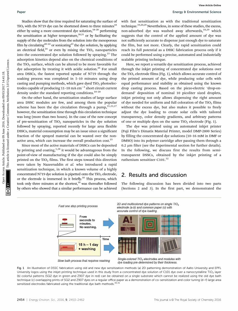
Here, we report a versatile dye sensitization process, achievedthrough the inkjet printing of concentrated dye solutions overthe TiO2 electrode films (Fig. 1), which allows accurate control ofthe printed amount of dye, while producing solar cells withequal performance and stability as obtained using the knowndrop casting process. Based on the piezo-electric ‘drop-on-demand’ deposition of nominal 10 picoliter sized droplets,inkjet printing not only allows dispensing the right amountof dye needed for uniform and full coloration of the TiO2 filmswithout the excess dye, but also makes it possible to freelyadjust the dye loading to create solar cells with tailoredtransparency, color density gradients, and arbitrary patternsof one or multiple dyes on the same TiO2 electrode (Fig. 1).
The dye was printed using an automated inkjet printer(Fuji Film’s Dimatix Material Printer, model DMP-2800 Series)by filling the concentrated dye solutions (10–16 mM in DMF orDMSO) into its polymer cartridge after passing them through a0.2 mm filter (see the Experimental section for further details).In the following, we discuss first the results from semi-transparent DSSCs, obtained by the inkjet printing of aruthenium sensitizer C101.32
2. Results and discussion
The following discussion has been divided into two parts(Sections 2 and 3). In the first part, we demonstrated the
Fig. 1 An Illustration of DSSC fabrication using old and new dye sensitization methods (a) 2D patterning demonstration of Aalto University and EPFLUniversity logos using the inkjet printing technique used in this study from a concentrated dye solution of C101 dye over a nanocrystalline TiO2 layer(b) colorful patterns (SQ2 dye in green and Z907 dye in red) can be obtained on a single substrate which cannot be realized using the old dye bathtechnique (c) overlapping prints of SQ2 and Z907 dyes on a regular office paper as a demonstration of co-sensitization and color tuning (d–f) large areasensitized electrodes fabricated using the traditional dye bath methods.30,31
Paper Energy & Environmental Science
Ope
n A
cces
s A
rtic
le. P
ublis
hed
on 0
9 Ju
ne 2
016.
Dow
nloa
ded
on 0
9/03
/201
7 14
:41:
18.
Thi
s ar
ticle
is li
cens
ed u
nder
a C
reat
ive
Com
mon
s A
ttrib
utio
n 3.
0 U
npor
ted
Lic
ence
.View Article Online
This journal is©The Royal Society of Chemistry 2016 Energy Environ. Sci., 2016, 9, 2453--2462 | 2455
potential capabilities of inkjet printing by using the semi-transparent DSSCs produced through efficient control of dyeloadings on nanocrystalline mesoporous TiO2 layers (no scatteringlayers were employed), whereas in the second part, the stability ofprinted dye is investigated in the standard DSSCs employing thescattering TiO2 layers.
2.1. Demonstration of the capabilities of inkjet printingof the dye
2.1.1. Variable transparency, color density gradients andmulti-dye patterns in a single DSSC. One of the advantages ofinkjet printing is the controlled dispensing of fluid throughwhich the dye loading of the photoelectrode can be accuratelycontrolled. To demonstrate this capability, and to determinethe printing parameters that yield full coloration, a 10 mMsolution of C101 dye in DMF was inkjet-printed 1–5 times(1.1 mL cm�2 per print) over a 7 mm thick TiO2 electrode(0.4 cm2, without a scattering layer) using 10 pL drop volumeand 30 mm drop spacing, which corresponds to 11.3 nmol cm�2
of dispensed dye per print. After a settling period of ca. 1 minute,
during which the dye attached on the TiO2 surface from theprinted solution, the films were rinsed with DMF (‘‘washed’’samples) to remove the possible non-adsorbed dye, or therinsing step was omitted (‘‘non-washed’’ samples). The photo-electrodes were then prepared for fully sealed solar cells (seethe Experimental section) and their optical transmittance andabsorptance (Fig. 2a–d), dye loading (Fig. 3a) and photovoltaicperformance (Fig. 4a–f) were measured. Reference samples wereprepared using the conventional ‘‘rapid sensitization’’ by spreading70–80 mL (175–200 mL cm�2) of the same dye solution on anidentical TiO2 film using a pipette (‘‘drop-cast’’ samples),followed by the same 15 minute settling and final rinsing asdone for the washed inkjet-printed samples.
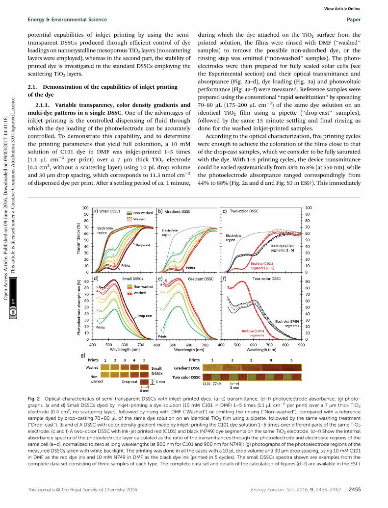
According to the optical characterization, five printing cycleswere enough to achieve the coloration of the films close to thatof the drop-cast samples, which we consider to be fully saturatedwith the dye. With 1–5 printing cycles, the device transmittancecould be varied systematically from 38% to 8% (at 550 nm), whilethe photoelectrode absorptance ranged correspondingly from44% to 88% (Fig. 2a and d and Fig. S3 in ESI†). This immediately
Fig. 2 Optical characteristics of semi-transparent DSSCs with inkjet-printed dyes: (a–c) transmittance, (d–f) photoelectrode absorbance, (g) photo-graphs. (a and d) Small DSSCs dyed by inkjet-printing a dye solution (10 mM C101 in DMF) 1–5 times (1.1 mL cm�2 per print) over a 7 mm thick TiO2
electrode (0.4 cm2, no scattering layer), followed by rising with DMF (‘‘Washed’’) or omitting the rinsing (‘‘Non-washed’’), compared with a referencesample dyed by drop-casting 70–80 mL of the same dye solution on an identical TiO2 film using a pipette, followed by the same washing treatment(‘‘Drop-cast’’). (b and e) A DSSC with color density gradient made by inkjet-printing the C101 dye solution 1–5 times over different parts of the same TiO2
electrode. (c and f) A two-color DSSC with ink-jet printed red (C101) and black (N749) dye segments on the same TiO2 electrode. (d–f) Show the internalabsorbance spectra of the photoelectrode layer calculated as the ratio of the transmittances through the photoelectrode and electrolyte regions of thesame cell (a–c), normalized to zero at long wavelengths (at 800 nm for C101 and 900 nm for N749); (g) photographs of the photoelectrode regions of themeasured DSSCs taken with white backlight. The printing was done in all the cases with a 10 pL drop volume and 30 mm drop spacing, using 10 mM C101in DMF as the red dye ink and 10 mM N749 in DMF as the black dye ink (printed in 5 cycles). The small DSSCs spectra shown are examples from thecomplete data set consisting of three samples of each type. The complete data set and details of the calculation of figures (d–f) are available in the ESI.†
Energy & Environmental Science Paper
Ope
n A
cces
s A
rtic
le. P
ublis
hed
on 0
9 Ju
ne 2
016.
Dow
nloa
ded
on 0
9/03
/201
7 14
:41:
18.
Thi
s ar
ticle
is li
cens
ed u
nder
a C
reat
ive
Com
mon
s A
ttrib
utio
n 3.
0 U
npor
ted
Lic
ence
.View Article Online
2456 | Energy Environ. Sci., 2016, 9, 2453--2462 This journal is©The Royal Society of Chemistry 2016
shows the unique feature of dye-sensitization using inkjet-printing that could be interesting for many applications of thesemi-transparent DSSCs: the transparency of the devices can befine-tuned by the dispensed amount of dye without changingthe thickness of the TiO2 film. This is exactly opposite to theconventional dyeing processes that produce fully dye-saturatedfilms with transmittance dictated by their thickness.
The other interesting feature of inkjet printing alreadymentioned is that it allows printing almost arbitrary dye patterns(Fig. 1). Fig. 2g shows this capability in more detail by demon-strating the two most obvious opportunities it implies: thecreation of dye patterns with varying color density (‘‘gradientDSSC’’) and combinations of multiple dyes (‘‘two-color DSSC’’)on the same photoelectrode. The optical characteristics ofthe five individual segments in the gradient DSSC, dyed with1–5 prints of the C101 dye, are similar to those observed in thesmall individual DSSCs, but produced on the same long TiO2
electrode stripe (Fig. 2b and e vs. Fig. 2a and d). In the two-color
DSSC, the characteristic absorptance spectra of the printed red(C101) or black (N749) dyes can be distinguished from theadjacent segments without any signs of mixing between them(Fig. 2c and f). This shows that inkjet printing accurately fixedthe dyes in their own segments, allowing multicolored dyepatterns to be produced on the same electrode. Note howuniform the coloration is in each segment of the two-colorDSSC (Fig. 2g), and how repeatable the color density is betweenthem, especially for the red dye (Fig. 2c and f). Although thecoloration is less uniform in the gradient DSSC with 1–3 prints,it improves substantially with the successive 4th and 5th prints,and is remarkably good in the small DSSCs, even with a singleprint, so that practically no visual difference can be seen betweenthe five-time printed and drop-cast samples (Fig. 2g).
2.1.2. Precise control of dye loading. Washing the TiO2
films after printing the dye affected neither their optical absorbancenor visual appearance (Fig. 2d and g), and no traces of the dyecould be seen in the transmittance spectra recorded from the
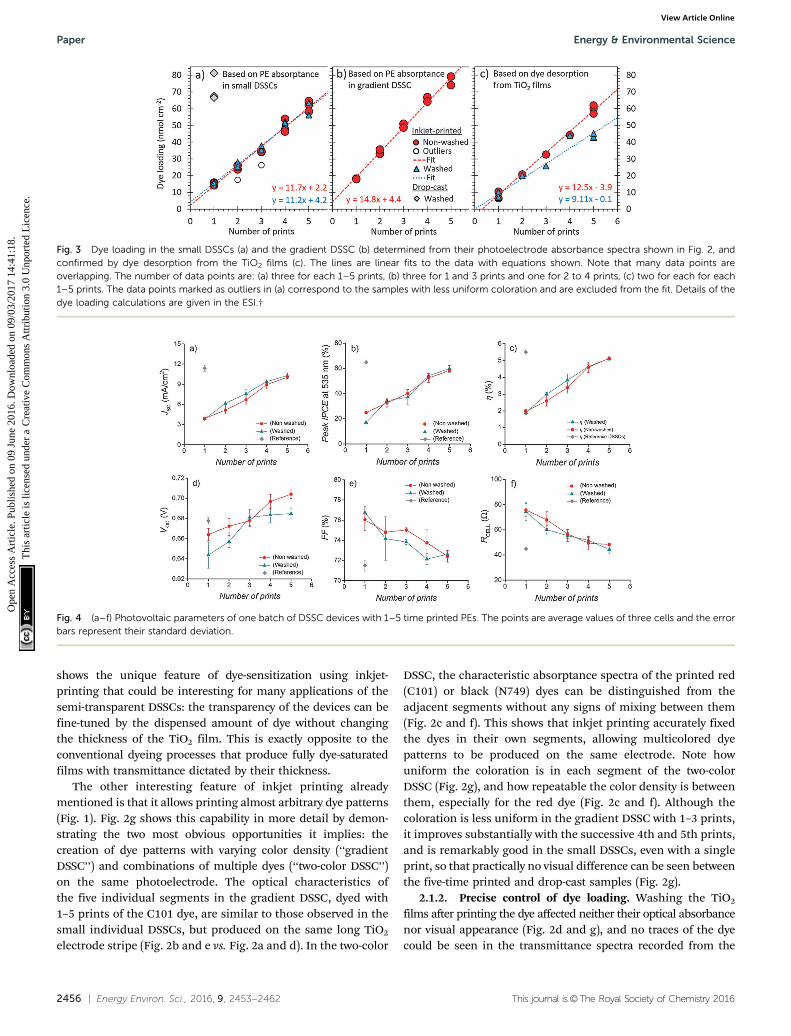
Fig. 3 Dye loading in the small DSSCs (a) and the gradient DSSC (b) determined from their photoelectrode absorbance spectra shown in Fig. 2, andconfirmed by dye desorption from the TiO2 films (c). The lines are linear fits to the data with equations shown. Note that many data points areoverlapping. The number of data points are: (a) three for each 1–5 prints, (b) three for 1 and 3 prints and one for 2 to 4 prints, (c) two for each for each1–5 prints. The data points marked as outliers in (a) correspond to the samples with less uniform coloration and are excluded from the fit. Details of thedye loading calculations are given in the ESI.†
Fig. 4 (a–f) Photovoltaic parameters of one batch of DSSC devices with 1–5 time printed PEs. The points are average values of three cells and the errorbars represent their standard deviation.
Paper Energy & Environmental Science
Ope
n A
cces
s A
rtic
le. P
ublis
hed
on 0
9 Ju
ne 2
016.
Dow
nloa
ded
on 0
9/03
/201
7 14
:41:
18.
Thi
s ar
ticle
is li
cens
ed u
nder
a C
reat
ive
Com
mon
s A
ttrib
utio
n 3.
0 U
npor
ted
Lic
ence
.View Article Online
This journal is©The Royal Society of Chemistry 2016 Energy Environ. Sci., 2016, 9, 2453--2462 | 2457
free electrolyte region of the cells (Fig. 2a–c). This indicates thatall the printed dye had attached well to the TiO2 film, leaving noexcess or loosely bound dye that could be removed by washing orreleased into the electrolyte when built into a DSSC, even whenthe washing step had been omitted. The dye loading in the TiO2
films, estimated from the photoelectrode absorptance spectra asdetailed in the ESI,† confirms this by showing excellent agree-ment between the washed and non-washed samples (Fig. 3a).Moreover, the dye loading increases linearly with the number ofprints, demonstrating good control and repeatability of theprinting process. The average dye loading per print determinedfrom the slope of the linear fits is 11.2 nmol cm�2 in the washedand 11.7 nmol cm�2 in the non-washed samples, which matchesalmost perfectly with the dispensed amount (11.3 nmol cm�2)determined by the printer settings (drop volume, spacing, andconcentration). Note that the dye loading obtained with fiveprints (56–65 nmol cm�2) is only slightly below the valuesachieved by drop-casting (68–81 nmol cm�2), as one wouldexpect if the loading does not exceed the saturation limit, butis close to it (Fig. 3a). Similar results with excellent linearity arealso observed in the gradient DSSC, although at somewhathigher 14.8 nmol cm�2 loading per print (Fig. 3b). The relativelyhigh values with five prints (74–79 nmol cm�2), achieved withoutsigns of saturation in the linear trend, indicate a somewhathigher film thickness in the gradient DSSC compared to thesmall DSSCs.
To confirm these results, some of the inkjet-dyed TiO2 filmsfrom the same batch as those built into solar cells underwent adye desorption experiment, where the printed dye was detachedfrom the films to a desorption solution of known volumeand then quantified using UV-VIS absorbance spectroscopy(see the Experimental section and ESI†). The results correspondwell to those determined optically from the complete DSSCs:the dye loading increases linearly with the number of printswith slopes of 9.1 nmol cm�2 per print in the washed and12.5 nmol cm�2 per print in the non-washed samples (Fig. 3c),and the values per film thickness obtained with five prints(6.5 and 8.9 nmol cm�2 mm�1, respectively) are close to the valuesreported for the same dye by others (8.8 to 11.4 nmol cm�2 mm�1).33
Note that although the lower slope would suggest that washinghad removed a significant amount of dye from the films in thiscase, only small amounts (o6 nmol cm�2) were detected in thefive-time printed samples using UV-VIS spectroscopy, and nonein the samples printed 1–4 times (data not shown). We thereforeconsider that these lower loadings, which deviate from thegeneral trend more than the normal variation, resulted fromoccasionally failed printing cycles, which occurred in less than4% of all the 174 printing cycles constituting the results ofFig. 3a–c. Indeed, only four of the nine washed samples in Fig. 3cshow results below the linear trend of the non-washed ones,whereas the rest match well with it.
2.1.3. Photovoltaic performance of the semi-transparentDSSCs. Also the results from the photovoltaic characterizationshow clear trends without any significant differences betweenwashed and non-washed samples (Fig. 4). The short circuitphotocurrent density ( JSC) increases systematically with the
number of prints, reaching ca. B10.1 mA cm�2 with five prints(Fig. 4a), which is slightly lower than in the drop-cast samples(ca. B11.4 mA cm�2), as expected from their lower dye loading(Fig. 3a). The peak value of incident-photon-to-collected-electron efficiency (IPCE) and the energy conversion efficiency(Z) have similar trends to JSC, reaching 59% and 5.1%, respec-tively with the fifth print, compared to 65% and 5.5% by drop-casting (Fig. 4b and c). This shows that dye loading (lightabsorption) was the main performance determining factor ofthese cells, which is also reflected in the other JV character-istics: When more dye is printed on the TiO2 film of fixedthickness, the open circuit voltage (VOC) increases (Fig. 4d),because more photocurrent is generated per unit volume of thefilm while the recombination rate (‘dark current’) remainsmore or less constant. The same would happen if the lightintensity was increased instead.34 Finally, the fill factor (FF) andcell resistance (RCELL) follow qualitatively what is expectedbased on the evolution of JSC and VOC according to the electro-chemical device model of DSSCs:34 the decrease of FF (Fig. 4e)follows the increase of JSC, because the voltage losses caused bythe internal cell resistances at the maximum power increaseproportionally to the current density, whereas the dependenceof VOC on the photocurrent is weaker (logarithmic). On theother hand, the observed reduction of RCELL (Fig. 4f) with theincreasing number of prints is expected based on the concomitantincrease in VOC (Fig. 4d), because the recombination resistance ofthe photoelectrode, which is the main contributor to RCELL at theopen circuit, is a decreasing function of voltage.34
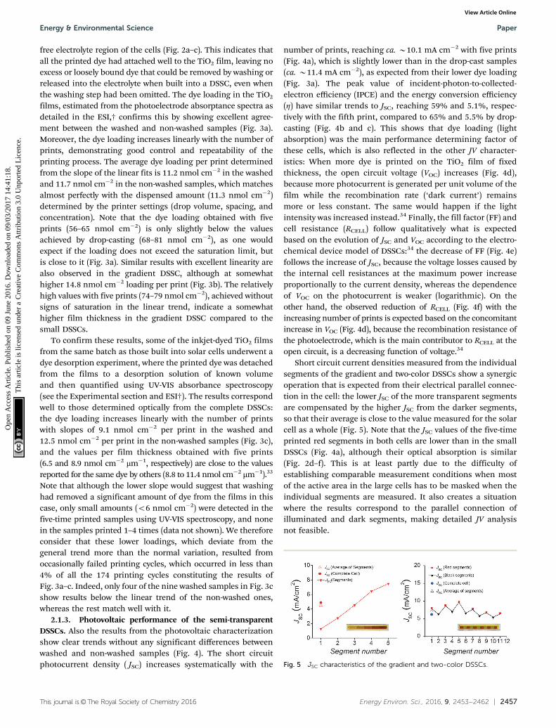
Short circuit current densities measured from the individualsegments of the gradient and two-color DSSCs show a synergicoperation that is expected from their electrical parallel connec-tion in the cell: the lower JSC of the more transparent segmentsare compensated by the higher JSC from the darker segments,so that their average is close to the value measured for the solarcell as a whole (Fig. 5). Note that the JSC values of the five-timeprinted red segments in both cells are lower than in the smallDSSCs (Fig. 4a), although their optical absorption is similar(Fig. 2d–f). This is at least partly due to the difficulty ofestablishing comparable measurement conditions when mostof the active area in the large cells has to be masked when theindividual segments are measured. It also creates a situationwhere the results correspond to the parallel connection ofilluminated and dark segments, making detailed JV analysisnot feasible.
Fig. 5 JSC characteristics of the gradient and two-color DSSCs.
Energy & Environmental Science Paper
Ope
n A
cces
s A
rtic
le. P
ublis
hed
on 0
9 Ju
ne 2
016.
Dow
nloa
ded
on 0
9/03
/201
7 14
:41:
18.
Thi
s ar
ticle
is li
cens
ed u
nder
a C
reat
ive
Com
mon
s A
ttrib
utio
n 3.
0 U
npor
ted
Lic
ence
.View Article Online
2458 | Energy Environ. Sci., 2016, 9, 2453--2462 This journal is©The Royal Society of Chemistry 2016
2.2. Verification of high performance and stability of theinkjet-dyed DSSCs
Keeping all the above advantages and capabilities of dye-sensitization by inkjet printing in mind, it was confirmed thatit is also entirely applicable for the preparation of traditional,non-transparent, high-efficiency DSSC designs. For this pur-pose, photoelectrodes consisting of an B12 mm thick meso-porous TiO2 layer and a 4–6 mm thick light scattering TiO2 layer(0.8 � 0.5 cm2 PE area) were sensitized by dispensing 5 � 1 mLvolume through 5 prints, which exhibited very minor impres-sions of the excess dye over the TiO2 scattering layer, and werenot rinsed further with the solvent.
The complete DSSCs were fabricated with these dye-printedphotoelectrodes by employing a sulfolane – ionic liquid elec-trolyte (coded as Z988)6 as the redox mediator along withplatinum (Pt) counter electrodes, and their initial and longterm stability performance was compared with the referenceDSSCs, which were fabricated by drop casting the knownvolumes (70–80 mL with 20–25 minute settling) of concentrated(10 mM in DMF) solution of the C101 dye over the similar PEs,followed by washing with DMF, using current–voltage ( JV)analysis, electrochemical impedance spectroscopy (EIS) andincident photon to collected electron (IPCE) measurements.
Statistical analysis of the average initial performance ofseven dye-printed DSSCs (efficiency 6.4 � 0.3%) and fivereference DSSCs (6.2� 0.4%) showed no statistically significantdifference between the two groups for any of the JV or EISparameters (Tables S1 and S4 in the ESI,† respectively). Mostimportantly, the two types of DSSCs showed almost equal shortcircuit current densities (14.0 � 0.2 mA cm�2 for printed dyeand 13.8 � 0.3 mA cm�2 for reference DSSCs), which confirmsthe successful sensitization process through inkjet printing.
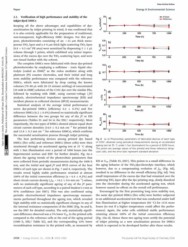
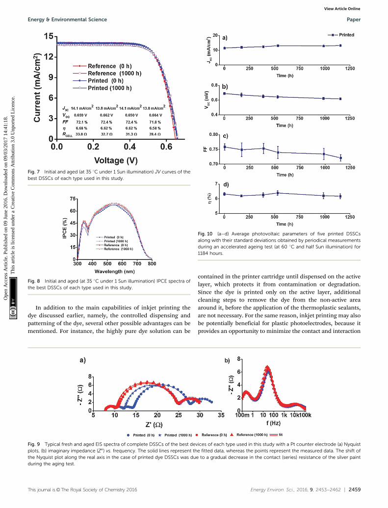
The best performing devices among printed dye basedDSSCs (five cells) and reference DSSCs (three cells) were thenmonitored through an accelerated ageing test at 35 1C alongwith 1 Sun illumination over a period of 1000 hours (see theExperimental section and ESI† for further details). Fig. 6a–eshows the ageing trends of the photovoltaic parameters thatwere collected from periodic measurements during the 1000 htest, and the initial and aged JV and IPCE curves of the bestDSSCs of each type are shown in Fig. 7 and 8, respectively. Theresults reveal highly stable performance retained at almost100% of the initial conversion efficiency (Z = 6.4 � 0.2%) andshort circuit current density ( JSC = 14.2 � 0.6 mA cm�2) values,with no statistically significant ageing of any of the JV para-meters of each cell type, according to a paired Student’s t-test at95% confidence (see ESI†). This was also confirmed usingperiodic electrochemical impedance spectroscopy measure-ments performed throughout the ageing test, which revealedhigh stability with no statistically significant changes in any ofthe internal resistance components of the DSSC (Fig. 9a and b,see the ESI† for detailed results). The only statistically signifi-cant difference observed was a 5% lower VOC in the printed cellscompared to the reference cells at the end of the aging period(1000 h, ESI,† Table S2), and the corresponding 14% lowerrecombination resistance in the printed cells, as measured by
EIS at VOC (Table S5, ESI†). This points to a small difference inthe aging behavior of the TiO2/dye/electrolyte interface, whichhowever, due to a compensating evolution of JSC (Fig. 6d),resulted in no difference in the overall efficiency (Fig. 6d). Verysmall impressions of the excess dye that had remained over thescattering TiO2 layer after the dye printing step, slowly dissolvedinto the electrolyte during the accelerated ageing test, whichhowever caused no effects on the overall cell performance.
Encouraged by the first promising long term stability test,the same dye printed DSSCs (five cells) were further subjectedto an additional accelerated test that was conducted under halfSun illumination at higher temperature (60 1C) for 1154 morehours (to test if a higher temperature could affect the perfor-mance). Again, the solar cells exhibited stable performanceretaining almost 100% of the initial conversion efficiency(Fig. 10a–d). Hence these two ageing tests certify the potentialof inkjet printing as a new sensitization process for DSSCswhich is expected to be developed further after these results.
Fig. 6 (a–e) Photovoltaic parameters of fabricated devices of each typeof DSSC obtained using periodical measurements during an acceleratedageing test (at 35 1C under 1 Sun illumination) for a period of 1000 hours.The points are average values of five printed and three reference (drop-cast) cells, and the error bars represent standard deviation.
Paper Energy & Environmental Science
Ope
n A
cces
s A
rtic
le. P
ublis
hed
on 0
9 Ju
ne 2
016.
Dow
nloa
ded
on 0
9/03
/201
7 14
:41:
18.
Thi
s ar
ticle
is li
cens
ed u
nder
a C
reat
ive
Com
mon
s A
ttrib
utio
n 3.
0 U
npor
ted
Lic
ence
.View Article Online
This journal is©The Royal Society of Chemistry 2016 Energy Environ. Sci., 2016, 9, 2453--2462 | 2459
In addition to the main capabilities of inkjet printing thedye discussed earlier, namely, the controlled dispensing andpatterning of the dye, several other possible advantages can bementioned. For instance, the highly pure dye solution can be
contained in the printer cartridge until dispensed on the activelayer, which protects it from contamination or degradation.Since the dye is printed only on the active layer, additionalcleaning steps to remove the dye from the non-active areaaround it, before the application of the thermoplastic sealants,are not necessary. For the same reason, inkjet printing may alsobe potentially beneficial for plastic photoelectrodes, because itprovides an opportunity to minimize the contact and interaction
Fig. 8 Initial and aged (at 35 1C under 1 Sun illumination) IPCE spectra ofthe best DSSCs of each type used in this study.
Fig. 9 Typical fresh and aged EIS spectra of complete DSSCs of the best devices of each type used in this study with a Pt counter electrode (a) Nyquistplots, (b) imaginary impedance (Z00) vs. frequency. The solid lines represent the fitted data, whereas the points represent the measured data. The shift ofthe Nyquist plot along the real axis in the case of printed dye DSSCs was due to a gradual decrease in the contact (series) resistance of the silver paintduring the aging test.
Fig. 7 Initial and aged (at 35 1C under 1 Sun illumination) JV curves of thebest DSSCs of each type used in this study.
Fig. 10 (a–d) Average photovoltaic parameters of five printed DSSCsalong with their standard deviations obtained by periodical measurementsduring an accelerated ageing test (at 60 1C and half Sun illumination) for1184 hours.
Energy & Environmental Science Paper
Ope
n A
cces
s A
rtic
le. P
ublis
hed
on 0
9 Ju
ne 2
016.
Dow
nloa
ded
on 0
9/03
/201
7 14
:41:
18.
Thi
s ar
ticle
is li
cens
ed u
nder
a C
reat
ive
Com
mon
s A
ttrib
utio
n 3.
0 U
npor
ted
Lic
ence
.View Article Online
2460 | Energy Environ. Sci., 2016, 9, 2453--2462 This journal is©The Royal Society of Chemistry 2016
of possibly harsh solvents with plastic substrates, such as thecommonly used indium doped tin oxide coated polyethyleneterephthalate (ITO-PET) and polyethylene naphthalate (ITO-PEN)sheets. For example, ITO-PET might swell when exposed tocertain solvents such as acetonitrile for long time periodsrequired in the traditional dye bath soaking process. Hence,we also aim to apply and investigate this technique on flexiblePEs in future. Again, unlike in the dye circulation process usedfor sensitizing the hermetically pre-sealed modules, in inkjetprinting the dye solution never comes in contact with the Ptcatalyst, which may help keep it clean of adsorbed dye moleculesthat could lower its catalytically active surface area. Moreover,the inkjet printing of dyes can also be potentially utilized formore accurate and controlled co-sensitization of TiO2 layersby multiple dyes, by printing them at optimized amounts overthe same electrode area, instead of controlling only the soakingtime, which is the traditional approach.
3. Conclusion
In conclusion, the TiO2 photoelectrodes of dye-sensitized solarcells (DSSCs) can be effectively stained by inkjet printingconcentrated dye solutions on them. The unique feature ofinkjet printing is that it allows accurate control of dye loadingwith respect to both the amount and position on the TiO2 film.This offers several advantages over the conventional dye appli-cation methods. First, close to full coloration can be achievedwithout rinsing off any excess dye, which simplifies the DSSCfabrication process and reduces material consumption. Second, thecolor density of the films can be tuned without changing theirthickness, which offers a new degree of freedom in the design ofsemi-transparent DSSCs, for example, for building integrated photo-voltaics. Third, the high spatial resolution of inkjet printing makes itpossible to create color density gradients and patterns of multipledyes on the same photoelectrode, which suggests a new avenue forcreating multi-colored DSSC designs attractive, for example, forstylish product integration of DSSCs. The inkjet printing of dyes isapplicable with or without a light scattering TiO2 layer, and yieldsstable devices with performance equal to those prepared using themanual drop casting sensitization process. Since inkjet printing isone of the most well-known, established and scalable techniques formanufacturing printed electronics, this new dye-sensitizationprocess could be readily adopted in the industrial settings,possibly even in the high throughput roll-to-roll production offlexible DSSC devices. Combined with our previously reportedinkjet printing of electrolytes,36 the results presented here showa path towards fully inkjet-printed DSSCs.
4. ExperimentalMaterials
Chloroplatinic acid hydrate (H2PtCl4�6H2O, purity 99.9%),guanidine thiocyanate (GuSCN, purity 499%), 1-methyl-benzimidazole (NMBI, purity 99%), all the solvents (sulfolane99% purity, 2-propanol 99.5% anhydrous, acetonitrile 99.8%
anhydrous, N,N-dimethylformamide (DMF) 99.8% purity) andthe titanium(IV) chloride tetrahydrofuran complex wereobtained from Sigma Aldrich. 1,3-Dimethylimidazolium iodide(DMII), 1-methyl-3-propylimidazolium (PMII 498% purity),1-ethyl-3-methylimidazolium iodide (EMII 498% purity) and1-ethyl-l-3-methylimidazolium tetracyanoborate (EMITCB) werepurchased from Merck. TiO2 nanocrystalline paste (18-NRT,20 nm) and TiO2 scattering paste (WER 2–0, 400 nm) werepurchased from Dyesol. Dye C101 and electrolyte Z988 wereproduced as reported earlier.6,32,35 Dyes N749 and SQ2 wereobtained from Solaronix, whereas dye Z907 was purchasedfrom Dyesol. Solvent dimethyl sulfoxide (DMSO, ultra-puregrade) was purchased from Amresco.
TiO2 photoelectrodes (PE)
The photoelectrodes for this experiment were prepared asfollows. Fluorine doped tin oxide (FTO) coated NSG-Glasssubstrates (area = 1.6 cm � 2.0 cm and sheet resistance10 O sq�1) were first washed and sonicated with a detergent(10 minutes). The substrates were further washed and soni-cated with acetone and ethanol solvents (5 minutes each) andwere dried with compressed air. These substrates were thenplaced and cleaned (15 minutes) in a UV-O3 cleaner (BioforceNanosciences USA). After cleaning in a UV-O3 chamber, thesubstrates were immersed in 40 mM TiCl4 solution and heated(30 minutes) in a preheated programmable oven and weresequentially rinsed with deionized water (DIW) and ethanoland were again dried with compressed air. The TiO2 layers(12 mm of nanocrystalline TiO2 particles, 20 nm and 4 mm thicklayer of scattering particles, 400 nm) were sequentially screenprinted and sintered at 450 1C for 30 minutes in the program-mable oven and were cooled down to room temperature. Then,the photoelectrodes were re-heated in the 40 mM TiCl4 aqueoussolution and were washed again with DIW and ethanol andwere dried with compressed air. Then, the photoelectrodeswere again sintered at 450 1C in the programmable oven andwere cooled down before the dye sensitization step. Note thatthe photoelectrodes for the dye desorption test (Fig. 3a and b)and for the dataset of DSSCs presented in Fig. 4(a–f) werenot subjected to any TiCl4 treatment and were not havingany scattering layers, but only the semi-transparent TiO2 layer(thickness 7 mm).
Dye solution formulations for inkjet printing
In the case of red C101 and black N749 (Fig. 1a and 2–10) thedye solution was 10 mM in DMF. In the case of blue SQ2 andred Z907 dyes (Fig. 1b and c), stock solutions were prepared(for individual dye) by dissolving 45 mg of dyes (SQ2 or Z907) in3 mL of solvent dimethyl sulfoxide (DMSO). Both DMF andDMSO were found to be suitable solvents for inkjet printingthese dyes.
Details of inkjet printing of dyes
Dye printing was achieved using an automated inkjet printer(Fuji Film’s Dimatix Material Printer, Model DMP-2800 Series,see Fig. S4 in the ESI†) by filling the concentrated dye solutions
Paper Energy & Environmental Science
Ope
n A
cces
s A
rtic
le. P
ublis
hed
on 0
9 Ju
ne 2
016.
Dow
nloa
ded
on 0
9/03
/201
7 14
:41:
18.
Thi
s ar
ticle
is li
cens
ed u
nder
a C
reat
ive
Com
mon
s A
ttrib
utio
n 3.
0 U
npor
ted
Lic
ence
.View Article Online
This journal is©The Royal Society of Chemistry 2016 Energy Environ. Sci., 2016, 9, 2453--2462 | 2461
(dye C101 and N749) into its polymer cartridge. Additionally,the cartridge is equipped with a so-called ‘print head’ whichconsists of 16 micro-channels (orifices) through which thesolution was dispensed. In order to get good printing results,the dye solution was passed through a 0.2 mm filter as recom-mended in the operating instructions of the printer. The TiO2
layers (actual area = 0.8 � 0.5 cm2) without the scattering layerwere sensitized with both dye solutions at 10 mM concentrationusing a 30 mm drop spacing leading 0.45 mL solution and4.5 nmol of dye deposition per cycle. See Fig. 2 caption formore details. The cells which underwent the ageing study wereassembled employing a scattering layer on nanocrystalline TiO2
and they were processed with a 20 mm drop spacing corres-ponding to 1 mL solution and 16 nmol of dye per print from16 mM solution. The printing process took around 3 and2 minutes for 20 mm and 30 mm drop spacing respectively.
Photoelectrode sensitization for reference DSSCs
The TiO2 layers of the photoelectrodes for the reference DSSCswere sensitized using a similar procedure as reported earlier forquick sensitization of dye C101.33 In brief, the TiO2 layers werecompletely covered by spreading the dye solution of knownvolumes (70 mL) with similar concentrations (10–16 mM of dyeC101 dye in DMF) as used in the inkjet printing of the dye andwere left for 20 minutes in a sealed plastic box. After that eachphotoelectrode was washed with DMF to remove the excess dyeand was dried with compressed air before the cell assembly.
Counter electrodes (CE)
A drop (4 mL) of 10 mM chloroplatinic acid hydrate (H2PtCl4�6H2O) solution (in 2 propanol) was cast over pre-cleaned FTOcoated glass substrates (TEC 7) and was fired at 410 1C for20 minutes. After that all the electrodes were cooled down toroom temperature and were placed in a tightly sealed plasticbox prior to the final cell assembly.
Electrolyte composition
The ionic liquid electrolyte coded as Z988 with the followingcomposition was used for this study: DMII/EMII/EMITCB/I2/NMBI/GuSCN (molar ratio 12 : 12 : 16 : 1.67 : 3.33 : 0.67) mixedand diluted with 50% of sulfolane (v/v).
Cell assembly
The cell channel was defined by separating PE and CE througha thick (25 mm) Surlyn frame foil. The ionic liquid electrolytewas introduced into the cell channel through the drilled holesat the CE side. The cells were then sealed with 25 mm thickSurlyn foil and a thin glass cover. At last, the contacts werefabricated by applying the copper tape and quick drying silverpaste at the non-active area of the electrodes.
Measurements
The JV curves of the DSSCs were recorded in a xenon lamp basedsolar simulator (Peccell Technologies, Japan, Model PEC-L01)under 1000 W m�2 light intensity calibrated to equivalent 1 Sunconditions using a reference solar cell (PV Measurements Inc.),
by using a black tape mask (aperture area 0.17 cm2). The electro-chemical impedance spectra were recorded from 100 mHz to100 kHz under open circuit conditions at 1000 W m�2 lightintensity on a Zahner-Elektrik IM6 electrochemical work-station, and analyzed using Zview2 software (Scribner AssociatesInc.) using the well-known equivalent circuit model of DSSCs.34
The incident photon to collected electron efficiency (IPCE) andtransmittance spectra were measured using a QEX7 spectralresponse measurement unit (PV Measurements Inc.) at nearnormal incidence without bias light. The first stability test ofthe solar cells was performed by keeping them for 1000 hoursunder open circuit conditions at 35 1C in a self-made solarsimulator under 1 Sun light intensity provided through halogenlamps (Philips 13117) and a UV filter (Asmetec GmbH, 400 nmcut-off), while recording their JV curves periodically in the above-mentioned separate solar simulator (Peccell Technologies,Japan). The second stability test was executed in the SuntestCPS Plus system at 60 1C under half Sun light illumination andsimilar periodic measurements as mentioned above were per-formed to record the JV curves in the solar simulator. The dyeloading (mol cm�2) in complete solar cells was determinedbased on two transmittance measurements from each cell: onetaken through the photoelectrode and one through the elec-trolyte filled edge region next to it. The dye loading in freshlysensitized TiO2 films was determined by desorbing the dyein a mixed solution of TMAOH and DMF (50/50 by volume).The decadic molar attenuation coefficient of C101 dye (17.5 �103 M�1 cm�1) used in the calculations was taken from ref. 33.The details of both methods are given in the ESI.†
Acknowledgements
G. H. gratefully acknowledges the Academy of Finland for thepost-doctoral research fellowship (Grant number: 287641). J. H.acknowledges the financial support from the Technology Industriesof Finland Centennial Foundation (NIR-DSC project). M. G.acknowledges financial support from Swiss National ScienceFoundation and CTI 17622.1 PFNM-NM, glass2energy SA (g2e),Villaz-St-Pierre, Switzerland. This work was also supported by theSELECT + (Environomical pathways for sustainable energy services).Bioeconomy infrastructure is also acknowledged for the use of theequipment.
References
1 G. Hashmi, K. Miettunen, T. Peltola, J. Halme, I. Asghar,K. Aitola, M. Toivola and P. Lund, Renewable SustainableEnergy Rev., 2011, 15, 3717–3732.
2 A. Feltrin and A. Freundlich, Ren. Energy, 2006, 33, 180–185.3 C. S. Tao, J. Jiang and M. Tao, Sol. Energy Mater. Sol. Cells,
2011, 95, 3176–3180.4 A. Hinsch, W. Veurman, H. Brandt, K. Flarup Jensen and
S. Mastroianni, ChemPhysChem, 2014, 15, 1076–1087.5 K. Zhang, C. Qin, X. Yang, A. Islam, S. Zhang, H. Chen and
L. Han, Adv. Energy Mater., 2014, 4, 1301966.
Energy & Environmental Science Paper
Ope
n A
cces
s A
rtic
le. P
ublis
hed
on 0
9 Ju
ne 2
016.
Dow
nloa
ded
on 0
9/03
/201
7 14
:41:
18.
Thi
s ar
ticle
is li
cens
ed u
nder
a C
reat
ive
Com
mon
s A
ttrib
utio
n 3.
0 U
npor
ted
Lic
ence
.View Article Online
2462 | Energy Environ. Sci., 2016, 9, 2453--2462 This journal is©The Royal Society of Chemistry 2016
6 M. Marszalek, F. D. Arendse, J. D. Decoppet, S. S. Babkair,A. A. Ansari, S. S. Habib, M. Wang, S. M. Zakeeruddin andM. Gratzel, Adv. Energy Mater., 2014, 4, 1301235.
7 Z. L. Wang and W. Wu, Angew. Chem., 2012, 51, 2–24.8 F. De Rossi, T. Pontecorvo and T. M. Brown, Appl. Energy,
2015, 156, 413–422.9 S. Vignati, MSc thesis, Comm. Syst. Dept., KTH, 2012.
10 S. Ito, T. N. Murakami, N. Takurou, P. Comte, P. Liska,C. Graetzel, M. K. Nazeeruddin and M. Graetzel, Thin SolidFilms, 2008, 516, 4613–4619.
11 M. K. Nazeeruddin, A. Kay, I. Rodicio, R. Humphry-Baker,E. Mueller, P. Liska, N. Vlachopoulos and M. Graetzel,J. Am. Chem. Soc., 1993, 115, 6382–6390.
12 M. Hosel, H. F. Dam and F. C. Krebs, Energy Technol., 2015,3, 293–304.
13 J. E. Carle, M. Helgesen, M. V. Madsen, E. Bundgaard andF. C. Krebs, J. Mater. Chem. C, 2014, 2, 1290–1297.
14 D. Angmo, S. A. Gevorgyan, T. T. L. Olsen, R. R. Søndergaard,M. Hosel, M. Jørgensen, R. Gupta, G. U. Kulkarni and F. C.Krebs, Org. Electron., 2013, 14, 984–994.
15 J. S. Yu, I. Kim, J. S. Kim, J. Jo, T. T. L. Olsen, R. R.Søndergaard, M. Hosel, D. Angmo, M. Jørgensen andF. C. Krebs, Nanoscale, 2012, 4, 6032–6040.
16 J. Adams, G. D. Spyropoulos, M. Salvador, N. Li, S. Strohm,L. Lucera, S. Langner, F. Machui, H. Zhang, T. Ameri,M. M. Voigt, F. C. Krebs and C. J. Brabec, Energy Environ.Sci., 2015, 8, 169–176.
17 K. Liu, T. T. Larsen-Olsen, Y. Lin, M. Beliatis, E. Bundgaard,M. Jørgensen, F. C. Krebs and X. Zhan, J. Mater. Chem. A,2016, 4, 1044–1051.
18 M. K. Nazeeruddin, R. Splivallo, P. Liska, P. Comte andM. Gratzel, Chem. Commun., 2003, 1456–1457.
19 I. Concina, E. Frison, A. Braga, S. Silvestrini, M. Maggini,G. Sberveglieri, A. Vomieroa and T. Carofiglio, Chem. Commun.,2011, 47, 11656–11658.
20 P. J. Holliman, M. L. Davies, A. Connell, B. V. Velasco andT. M. Watson, Chem. Commun., 2010, 46, 7256–7258.
21 M. Spath, P. M. Sommeling, J. A. M. van Roosmalen, H. J. P.Smit, N. P. G. van der Burg, D. R. Mahieu, N. J. Bakker andJ. M. Kroon, Prog. Photovoltaics, 2003, 11, 207–220.
22 R. Sastrawan, J. Beier, U. Belledin, S. Hemming, A. Hinsch,R. Kern, C. Vetter, F. M. Petrat, A. P. Schwab, P. Lechner andW. Hoffmann, Sol. Energy Mater. Sol. Cells, 2006, 90,1680–1691.
23 Y. Seo and J. H. Kim, J. Ind. Eng. Chem., 2013, 19, 488–492.24 H. Seo, M. K. Son, I. Shin, J. K. Kim, K. J. Lee, K. Prabakar
and H. J. Kim, Electrochim. Acta, 2010, 55, 4120–4123.25 H. G. Han, H. C. Weerasinghe, K. M. Kim, J. S. Kim,
Y. B. Cheng, D. J. Jones, A. B. Holmes and T. H. Kwon,Sci. Rep., 2015, 5, 14645.
26 B. Kim, S. W. Park, J. Y. Kim, K. Yoo, J. Ah Lee, M. W. Lee,D. K. Lee, J. Y. Kim, B. S. Kim, H. Kim, S. Han, H. J. Son andM. J. Ko, ACS Appl. Mater. Interfaces, 2013, 5, 5201–5207.
27 R. Sastrawan, J. Beier, U. Belledin, S. Hemming, A. Hinsch,R. Kern, C. Vetter, F. M. Petrat, A. P. Schwab, P. Lechner andW. Hoffmann, Prog. Photovoltaics, 2006, 14, 697–709.
28 S. G. Hashmi, T. Moehl, J. Halme, Y. Ma, T. Saukkonen,A. Yella, F. Giordano, J. D. Decoppet, S. M. Zakeeruddin,P. Lund and M. Gratzel, J. Mater. Chem. A, 2014, 2,19609–19615.
29 S. C. Yeh, P. H. Lee, H. Y. Liao, Y. Y. Chen, C. T. Chen,R. J. Jeng and J. J. Shuye, ACS Sustainable Chem. Eng., 2015,3, 71–81.
30 Fig. 1e is reprinted from, H. Arakawa, T. Yamaguchi,T. Sutou, Y. Koishi, N. Tobe, D. Matsumoto and T. Nagai,Efficient dye-sensitized solar cell sub-modules, Curr. Appl.Phys., 2010, 10(2), S157–S160, with permission fromElsevier.
31 Fig. 1f is reprinted from, H. Pettersson, T. Gruszecki,C. Schnetz, M. Streit, Y. Xu, L. Sun, M. Gorlov, L. Kloo,G. Boschloo, L. Haggman and A. Hagfeldt, Parallel-connected monolithic dye-sensitised solar modules, Prog.Photovoltaics, 2010, 18, 340–345, with permission from JohnWiley and Sons.
32 F. Gao, Y. Wang, D. Shi, J. Zhang, M. Wang, X. Jing,R. H. Baker, P. Wang, S. M. Zakeeruddin and M. Gratzel,J. Am. Chem. Soc., 2008, 130, 10720–10728.
33 M. Wang, S. Plogmaker, R. H. Baker, P. Pechy, H. Rensmo,S. M. Zakeeruddin and M. Gratzel, ChemSusChem, 2012, 5,181–187.
34 J. Halme, P. Vahermaa, K. Miettunen and P. Lund,Adv. Mater., 2010, 22, E210–E234.
35 J. D. Decoppet, T. Moehl, S. S. Babkair, R. A. Alzubaydi,A. A. Ansari, S. S. Habib, S. M. Zakeeruddin, H. W. Schmidtand M. Gratzel, J. Mater. Chem. A, 2014, 2, 15972–15977.
36 S. G. Hashmi, M. Ozkan, J. Halme, K. Dimic-Misic,S. M. Zakeeruddin, J. Paltakari, M. Gratzel and P. D. Lund,Nano Energy, 2015, 17, 206–215.
Paper Energy & Environmental Science
Ope
n A
cces
s A
rtic
le. P
ublis
hed
on 0
9 Ju
ne 2
016.
Dow
nloa
ded
on 0
9/03
/201
7 14
:41:
18.
Thi
s ar
ticle
is li
cens
ed u
nder
a C
reat
ive
Com
mon
s A
ttrib
utio
n 3.
0 U
npor
ted
Lic
ence
.View Article Online