Embed Size (px)
Citation preview

8/11/2019 Development of Advanced Methods for Joining Low-Alloy Steels
http://slidepdf.com/reader/full/development-of-advanced-methods-for-joining-low-alloy-steels 1/58
Development of Advanced Methods
for Joining Low-Alloy Steels
Technical Report L
I
C
E N
S E D
M A T
E R
I
A
L WARNING:
Please read the License Agreement
on the back cover before removing
the Wrapping Material.
Effective December 6, 2006, this report has been made publicly available in accordance with
Section 734.3(b)(3) and published in accordance with Section 734.7 of the U.S. Export
Administration Regulations. As a result of this publication, this report is subject to only
copyright protection and does not require any license agreement from EPRI. This notice
supersedes the export control restrictions and any proprietary licensed material notices
embedded in the document prior to publication.

8/11/2019 Development of Advanced Methods for Joining Low-Alloy Steels
http://slidepdf.com/reader/full/development-of-advanced-methods-for-joining-low-alloy-steels 2/58

8/11/2019 Development of Advanced Methods for Joining Low-Alloy Steels
http://slidepdf.com/reader/full/development-of-advanced-methods-for-joining-low-alloy-steels 3/58
EPRI Project ManagersK. ColemanD. Gandy
EPRI 3412 Hillview Avenue, Palo Alto, California 94304 • PO Box 10412, Palo Alto, California 94303 • USA800.313.3774 • 650.855.2121 • [email protected] • www.epri.com
Development of Advanced Methodsfor Joining Low-Alloy Steels
1004527
Interim Report, March 2003
CosponsorMetrode Products Ltd.Hanworth Lane
Chertsey, Surrey, KT16 9LLUnited Kingdom

8/11/2019 Development of Advanced Methods for Joining Low-Alloy Steels
http://slidepdf.com/reader/full/development-of-advanced-methods-for-joining-low-alloy-steels 4/58

8/11/2019 Development of Advanced Methods for Joining Low-Alloy Steels
http://slidepdf.com/reader/full/development-of-advanced-methods-for-joining-low-alloy-steels 5/58
iii
CITATIONS
This report was prepared by
Metrode Products Ltd.Hanworth LaneChertsey, Surrey, KT16 9LLUnited Kingdom
Principal InvestigatorsG. Hollaway
A. MarshallJ. Sanserson
This report describes research sponsored by EPRI.
The report is a corporate document that should be cited in the literature in the following manner:
Development of Advanced Methods for Joining Low-Alloy Steels, EPRI, Palo Alto, CA, andMetrode Products Ltd., Chertsey, U.K.: 2003. 1004527.

8/11/2019 Development of Advanced Methods for Joining Low-Alloy Steels
http://slidepdf.com/reader/full/development-of-advanced-methods-for-joining-low-alloy-steels 6/58
8/11/2019 Development of Advanced Methods for Joining Low-Alloy Steels
http://slidepdf.com/reader/full/development-of-advanced-methods-for-joining-low-alloy-steels 7/58
v
PRODUCT DESCRIPTION
In the late 1980s the domestic utility industry suffered from weld failures between low-alloyferritic tubing and austenitic tubing in superheaters and reheaters. This type of failure is knownin the industry as a dissimilar metal weld (DMW) failure. EPRI performed extensive researchinto the problem and found that nickel-based filler metals developed significant service lifeimprovements over 309 SS filler metals. Additionally, improved joint geometries and additionalweld-metal reinforcement have provided added service life. To give utilities even better servicelife, a new nickel-based filler metal was developed that had closer thermal-expansion propertiesto the low-alloy base metal. This new filler metal was never commercialized because of atendency to microfissure that resulted in less than desired service life.
With the development and use of higher-strength alloys in new power installations, specificallyGrade 91, EPRI Materials and Repair saw a need for further research into this filler metal. If themicrofissuring could be eliminated, this filler metal would offer substantial benefits in jointsbetween Grade 91 and Grade 91 pipes and tubes, as well as joints between Grade 91 and low-alloy ferritic or austenitic pipes and tubes.
Results and FindingsUse of this new filler metal should offer the utility industry several significant benefits overcurrently available filler metals including:
• High toughness in the as-welded condition
• Lower thermal expansion stresses in DMW applications
• The ability to eliminate Type IV cracking in Grade 91 weldments through selective heattreatments
• A filler metal that allows for elimination of field post-weld heat treatment (PWHT) of jointsin Grade 91 materials allowing for shortened construction or repair schedules
• Improved weld-joint ductility
Challenges and Objectives
This report should be read by welding and maintenance engineers, construction supervisors, andindividuals responsible for the construction and maintenance of power plants. The filler metaldeveloped by this project offers substantial improvements in the time required to make repairs tohigher-alloyed materials while demonstrating life improvements over currently available fillermetals.

8/11/2019 Development of Advanced Methods for Joining Low-Alloy Steels
http://slidepdf.com/reader/full/development-of-advanced-methods-for-joining-low-alloy-steels 8/58
vi
Applications, Values, and UseSimilar weld joints between creep-enhanced base metals (such as P91, P92, T23, T24, E911) andnon-similar joints between these alloys and low-allow ferritic or austenitic materials will beeasier to complete while offering improved life by use of the filler metal developed in thisproject. PWHT operations can be greatly simplified or eliminated. Repairs to components
manufactured from these alloys will be easier. Newer alloys under development will also benefitfrom this filler metal development.
EPRI PerspectiveEPRI has worked to solve the DMW problem for two decades. With the new alloys currently inuse or under development, application of existing and development of new technology will beparamount to the profitability of the utility industry.
ApproachA unique microfissuring test was developed to test the microfissuring tendency of over 55different chemical compositions of the proposed filler metal. Microfissuring of the existing alloyhas been eliminated through careful manipulation of up to 12 different elements in the fillermetal. The effect of each element is understood, and a specific range for each chemical in thenew filler metal has been defined. Phase II of this project is underway in which rupture testing ofthe filler metal in different applications will be conducted to document life improvement and costsavings through use of this improved filler metal.
KeywordsDissimilar metal weldGrade 91P91Post-weld heat treatment

8/11/2019 Development of Advanced Methods for Joining Low-Alloy Steels
http://slidepdf.com/reader/full/development-of-advanced-methods-for-joining-low-alloy-steels 9/58
EPRI Licensed Material
vii
ACKNOWLEDGMENTS
EPRI would like to take this opportunity to acknowledge the following for their contribution tothis report:
Euroweld Ltd.225 Rolling Hills RoadMooresville, NC 28117
W. Newell

8/11/2019 Development of Advanced Methods for Joining Low-Alloy Steels
http://slidepdf.com/reader/full/development-of-advanced-methods-for-joining-low-alloy-steels 10/58

8/11/2019 Development of Advanced Methods for Joining Low-Alloy Steels
http://slidepdf.com/reader/full/development-of-advanced-methods-for-joining-low-alloy-steels 11/58
EPRI Licensed Material
ix
CONTENTS
1 INTRODUCTION ................................................................................................................. 1-1
2 EXPERIMENTAL PROCEDURE ......................................................................................... 2-1
2.1 Alloy Development .................................................................................................... 2-2
2.1.1 Analysis............................................................................................................ 2-2
2.1.2 Microfissuring Tests.......................................................................................... 2-2
2.2 Metallography ........................................................................................................... 2-4
2.3 Mechanical Testing ................................................................................................... 2-4
2.3.1 Weld Test Plates .............................................................................................. 2-4
2.3.2 Ambient Temperature Tests ............................................................................. 2-5
2.3.3 Elevated Temperature Tests............................................................................. 2-5
2.3.4 N+T .................................................................................................................. 2-6
3 RESULTS AND DISCUSSION............................................................................................. 3-1
3.1 Microfissuring............................................................................................................ 3-1
3.1.1 Method of Microfissuring Assessment .............................................................. 3-1
3.1.2 Influence of Composition on Microfissuring....................................................... 3-4
3.1.3 Metallography ................................................................................................... 3-8
3.2 Ambient Temperature Tests.....................................................................................3-15
3.2.1 Tensile Tests ...................................................................................................3-15
3.2.2 Charpy Tests ...................................................................................................3-16
3.2.3 Side-Bend Tests..............................................................................................3-17
3.2.4 Radiography Tests ..........................................................................................3-17 3.3 Elevated Temperature Tests ....................................................................................3-18
3.3.1 Hot Tensile (As-Welded) Tests ........................................................................3-18
3.3.2 Hot Tensile (N+T) Tests...................................................................................3-25
3.3.3 Stress-Rupture Tests.......................................................................................3-25

8/11/2019 Development of Advanced Methods for Joining Low-Alloy Steels
http://slidepdf.com/reader/full/development-of-advanced-methods-for-joining-low-alloy-steels 12/58
EPRI Licensed Material
x
4 CONCLUSIONS .................................................................................................................. 4-1
5 REFERENCES AND BIBLIOGRAPHY................................................................................ 5-1
5.1 References................................................................................................................ 5-1
5.2 Bibliography .............................................................................................................. 5-1

8/11/2019 Development of Advanced Methods for Joining Low-Alloy Steels
http://slidepdf.com/reader/full/development-of-advanced-methods-for-joining-low-alloy-steels 13/58
EPRI Licensed Material
xi
LIST OF FIGURES
Figure 2-1 Microfissuring Assessment Buildups ...................................................................... 2-3
Figure 2-2 Dimensions of the Test Plates................................................................................ 2-4
Figure 2-3 Schematic Showing the Bead Sequence ............................................................... 2-5
Figure 3-1 D694 (MI = 1) - Dye Penetrant Examination - Schematic of the Original Dye-Penetrant Test................................................................................................................. 3-2
Figure 3-2 D717 (MI = 2) - Dye-Penetrant Examination - Schematic of the Original Dye-Penetrant Test................................................................................................................. 3-2
Figure 3-3 D929 (MI = 2) - Dye-Penetrant Examination - Schematic of the Original Dye-Penetrant Test................................................................................................................. 3-3
Figure 3-4 D930 (MI = 5) - Dye-Penetrant Examination - Schematic of the Original Dye-Penetrant Test................................................................................................................. 3-3
Figure 3-5 Microfissuring Index Plotted Against Manganese Content...................................... 3-5
Figure 3-6 Microfissuring Index Plotted Against Phosphorus Content ..................................... 3-6
Figure 3-7 Microfissuring Index Plotted Against Silicon Content.............................................. 3-7
Figure 3-8 Microfissuring Index Plotted Against Titanium Content........................................... 3-7
Figure 3-9 Microfissuring Index Plotted Against Aluminum Content ........................................ 3-8
Figure 3-10 D694 (MI = 1)....................................................................................................... 3-9
Figure 3-11 D717 (MI = 2)....................................................................................................... 3-9
Figure 3-12 D929 (MI = 4)......................................................................................................3-10
Figure 3-13 D930 – Within HFS6 Analysis Limits (MI = 5)......................................................3-10
Figure 3-14 D694 - Crack Stops About 0.5 mm (0.02 in.) Before the Top of the FinalBead (Note the Bead Surface Can Be Seen in the Top Right Corner). This CrackingAppears to Extend into the Final Bead. It Is Proposed That This May Have BeenCaused by the “Wash” of Weaving When the Bead Was Deposited, Resulting inParts of the Final Bead Undergoing Some Reheating.....................................................3-11
Figure 3-15 D929 - Crack Stops About 1 mm (0.4 in.) Before the Top of the Final Bead.The Microfissures Do Appear to Follow a Primary Grain Boundary. ...............................3-12
Figure 3-16 D930 (HFS6) – No Deliberate Nb and C .............................................................3-13 Figure 3-17 D694 – 1.5% Nb and 0.010% C. .........................................................................3-13
Figure 3-18 Macro Showing Transverse Section of Test Buildup (Original
Magnification × 4). ..........................................................................................................3-14
Figure 3-19 Micrograph Showing Detail from Above Macro, CMn Base Material at
Bottom (Original Magnification × 50)...............................................................................3-14
Figure 3-20 Hot Strength (1100°F/593°C) Variation with Alloy Content – Carbon...................3-20

8/11/2019 Development of Advanced Methods for Joining Low-Alloy Steels
http://slidepdf.com/reader/full/development-of-advanced-methods-for-joining-low-alloy-steels 14/58
EPRI Licensed Material
xii
Figure 3-21 Hot Strength (1100°F/593°C) Variation with Alloy Content - Niobium..................3-21
Figure 3-22 Strength Versus Temperature for Batch D724.....................................................3-22
Figure 3-23 Proof Stress/UTS Ratio Versus Ductility for Hot Tensile (1100°F/593°C)Tests. .............................................................................................................................3-24

8/11/2019 Development of Advanced Methods for Joining Low-Alloy Steels
http://slidepdf.com/reader/full/development-of-advanced-methods-for-joining-low-alloy-steels 15/58
EPRI Licensed Material
xiii
LIST OF TABLES
Table 1-1 Chemical Composition of HFS6 Electrode............................................................... 1-2
Table 2-1 Core Wire Analysis.................................................................................................. 2-1
Table 3-1 Room Temperature Tensile Properties of Batch D724 ...........................................3-16
Table 3-2 Room Temperature Impact Properties of Batch D724 ............................................3-17
Table 3-3 Radiographic Report Comments ............................................................................3-18
Table 3-4 Hot Tensile Results Carried Out at 1100°F (593°C) ...............................................3-19
Table 3-5 Comparison of Room and Elevated Temperature Strength for Batch D724............3-22
Table 3-6 Comparison of MI Ranking and the Surface Indications on the Gauge Lengthof the Fractured Hot Tensile Specimens.........................................................................3-23
Table 3-7 Comparison of As-Welded and N+T Hot Strength (1100°F [593°C]) of BatchD925 ..............................................................................................................................3-25
Table 3-8 Stress Rupture Results ..........................................................................................3-26

8/11/2019 Development of Advanced Methods for Joining Low-Alloy Steels
http://slidepdf.com/reader/full/development-of-advanced-methods-for-joining-low-alloy-steels 16/58

8/11/2019 Development of Advanced Methods for Joining Low-Alloy Steels
http://slidepdf.com/reader/full/development-of-advanced-methods-for-joining-low-alloy-steels 17/58
EPRI Licensed Material
1-1
1INTRODUCTION
This project was initiated to continue the work that was carried out up to 1987 and reported byEPRI [1]. The situation at that time was that a very promising weld-metal composition had beendeveloped, but it could not be exploited owing to its high susceptibility to microfissuring. Theobjective of the present project concerns the design and manufacture of an experimental creep-resisting shielded metal arc welding (SMAW) electrode to deposit microfissure-free weld metal,based as closely as possible on the findings of the previous work. The intent of the previousproject was to develop a weld metal suitable for dissimilar metal welds (DMWs) between ferriticsteels such as P22 and austenitic stainless steels in high-temperature applications in the power
generation industry, the most widespread applications being found in superheaters and reheatersof fossil fuel electric power generation boilers.
The earlier work carried out on behalf of EPRI identified a unique nickel-iron (Ni-Fe) SMAWelectrode composition as showing a number of advantages over existing types for use as adissimilar welding consumable. That situation is considered to be equally valid today. Thecomposition was identified as HFS6 [1], and the preliminary specification drawn up from theearlier work is given in Table 1-1. Not all of the batches of HFS6 tested in the earlier workconformed to this specification. Some examples of actual batch analyses are also given inTable 1-1.

8/11/2019 Development of Advanced Methods for Joining Low-Alloy Steels
http://slidepdf.com/reader/full/development-of-advanced-methods-for-joining-low-alloy-steels 18/58
E P R I L i c e n s e d M a t e r i a l
I n t r o d u c t i o n
1 - 2 T
a b l e 1 - 1
C h e m i c a l C o m p o s i t
i o n o f H F S 6 E l e c t r o d e [ 1 ]
B a t c h
C a r b o
n
( C )
S i l i c o n
( S i )
M a n g a n e s e
( M n )
P h o s p h o r
u s
( P )
S u l f u r
( S )
C h r o m i u n
( C r )
M o l y b d e n u
m
( M o )
I r o n
( F e )
A l u m i n u m
( A l )
N i o b i u m
( N b )
T i t
a n i u m
( T i )
N i c k e l
( N i )
S p e c i f i c a t i o n
0 . 0 4
0 . 7
5
0 . 9 - 1 . 5
0 . 0
1 5
0 . 0
1 5
7 . 5 - 9 . 5
1 . 5 - 2 . 5
B a l .
0 . 1
0 . 1
0 . 1
4 3 - 5 0
D I 2 9 5 6
0 . 0 9
0 . 1
3
0 . 8
2
0 . 0
0 1 5
-
8 . 0
5
1 . 7
9
B a l .
-
-
-
4 2 . 0
9 5 6 1 - 0 1 4
0 . 0 4
0 . 4
7
1 . 2
5
0 . 0
0 1
0 . 0
0 5
8 . 8
0
1 . 9
8
B a l .
-
-
-
4 4 . 3
2
6 5 6 8 - P 1 9 5 0 1
0 . 0 3
0 . 5
4
1 . 2
6
0 . 0
0 5
0 . 0
0 3
8 . 2
6
1 . 8
7
B a l .
0 . 0
1
-
0 . 0
3
4 3 . 3
6
6 5 6 8 - P 1 9 5 0 2
0 . 0 4
0 . 6
0
1 . 4
5
0 . 0
1 4
0 . 0
0 3
9 . 2
5
2 . 2
8
B a l .
0 . 0
4
-
0
. 0 1 1
4 7 . 6
5
1 .
A n a l y s i s f r o m a
w
e l d p a d .
2 .
T h i s w a s a c h e c k
a n a l y s i s o n t h e s a m e b a t c h a s ( 1 )
b u t f r o m a
w e l d p l a t e .

8/11/2019 Development of Advanced Methods for Joining Low-Alloy Steels
http://slidepdf.com/reader/full/development-of-advanced-methods-for-joining-low-alloy-steels 19/58
EPRI Licensed Material
Introduction
1-3
The high susceptibility of HFS6 to actual or incipient microfissuring was previouslydemonstrated in fissure-bend tests and perhaps most significantly in the gauge length oflongitudinal all-weld creep tests, which were judged to have failed at drastically shortenedrupture times in comparison with transverse weldment tests. Owing to the latter observation, all-weld hot tensile and/or short-term stress rupture assessment was important in the present work.
In the earlier work, microfissuring was not found in conventional transverse face and root-bendtests, so it was concluded that the orientation of microfissures was predominantly transverse tothe welding direction, and they were therefore not opened or discriminated by cross-weld creepand bend tests.
Solving the microfissuring problem was the principal deliverable of the present developmentwork, assisted by screening numerous alloy variants using a unique test method and leading tothe preparation of an optimized SMAW production formula for the subsequent manufacture ofpilot quantities for more extensive testing by EPRI.
Tests carried out in the earlier project included:
• Chemical analysis
• Hardness
• Bend tests
• Creep-rupture tests
• Thermal-expansion tests
• Thermal aging and carbon migration evaluation
• Microstructural studies
•Fissure bend tests
In the present work, testing so far has been restricted to:
• Analysis
• Microfissuring assessment
• Metallography
• Ambient mechanical testing
• Hot tensile testing in the as-welded and normalize and temper (N+T) condition
•
Ongoing work includes all-weld metal stress-rupture testing
In the earlier work, the intention was primarily to find a weld metal suitable for dissimilarwelding applications involving 300H series stainless steels (304H, 316H, 321H, 347H) and P11,P22, or P9 CrMo materials. The scope of the potential applications has now increased to includenot only P91 but also the possibility of using the new weld metal for producing stub pieces thatcould be used in the field to make as-welded joints in P91. This type of application would require

8/11/2019 Development of Advanced Methods for Joining Low-Alloy Steels
http://slidepdf.com/reader/full/development-of-advanced-methods-for-joining-low-alloy-steels 20/58
EPRI Licensed Material
Introduction
1-4
the dissimilar weld metal to retain sufficient strength to match the P91 base material following afull N+T heat treatment, so a preliminary investigation of tensile properties following N+T wasalso carried out as part of the current work.

8/11/2019 Development of Advanced Methods for Joining Low-Alloy Steels
http://slidepdf.com/reader/full/development-of-advanced-methods-for-joining-low-alloy-steels 21/58
EPRI Licensed Material
2-1
2EXPERIMENTAL PROCEDURE
The development work was carried out solely using 0.125 in. (3.2 mm) diameter SMAWelectrodes. Two different electrode-core wires were used (see Table 2-1), both nominallyNi-45%Fe, but one was a fully alloyed wire, while the other was pure nickel with an ironcladding. Both of these core wires are used by Metrode for manufacturing commercial cast ironelectrodes, and it was believed that the clad bi-metallic core wire would have significant benefitsbecause of its higher conductivity and therefore reduced overheating. The earlier report [1]indicated a Ni-50%Ni core wire but had no details of electrode coverings used, so all of the workwas based on flux systems developed by Metrode for similar alloy systems. This flux covering
was a fully basic fluoride-carbonate type, plus alloying additions and deoxidants, suitable for 6Gpipe welding using dc+ polarity (EXXX-15).
Table 2-1Core Wire Analysis
Core Wire C Mn Si S Ni Fe AlBatches on
Which the WireWas Used
1
Alloy 55 -Specification
0.15max.
1.50max.
0.50max.
0.015max.
54-64 Bal. 0.05-0.15 -
Alloy 55 -Cast 5027
0.03 0.53 0.06 0.003 56.87 42 0.070All series D onalloyed wire +C306 (5027)
Alloy 55 -Cast 8268
0.019 0.95 0.19 0.003 59.42 39 <0.01All series C onalloyed core wire
Clad 55 -Specification
0.15max.
1.50max.
0.50max.
0.020max.
52-60 34-36 - -
Clad 55 -Cast 277416
0.06 0.26 0.11 0.004 56.22 Bal. 0.005All batches onclad wire exceptD924 & D926
Clad 55 -Cast 49931
0.06 0.27 0.13 0.005 56.16 Bal. - D924 & D926
1. All batches made on clad core wire are identified in Table 2-1 with the suffix clad.

8/11/2019 Development of Advanced Methods for Joining Low-Alloy Steels
http://slidepdf.com/reader/full/development-of-advanced-methods-for-joining-low-alloy-steels 22/58
EPRI Licensed Material
Experimental Procedure
2-2
2.1 Alloy Development
Owing to the promising nature of the results on the original HFS6 electrodes, this compositionwas used as the starting point for the work in this project. It was considered important toreproduce compositions of good technical purity close to the original so that its susceptibility to
microfissuring could be confirmed and against which improvements could be calibrated.Throughout the work, the major alloying content Ni, Fe, Cr, and Mo were kept close to the levelsin HFS6, as shown in Table 1-1. The experimental plan involved producing numerous batches ofelectrodes in which the variations were primarily C, Mn, and niobium (Nb). The effect of C wasinvestigated up to ~0.12%, the effect of Mn up to ~2.3%, and the effect of Nb up to ~2.0%.
The three alloying additions C, Mn, and Nb were identified as potential means of reducing thetendency for microfissuring based on previous development work carried out by Metrode and byother published work. It was anticipated that there would be a threshold above which one ormore of these additions should substantially improve resistance to microfissuring compared tothe original HFS6, hopefully without deviating too far from the original. Manganese, forexample, was restricted to about 2% because it increases the thermal expansion coefficient.
The alloy development work was carried out in four main phases:
1. Looking at deoxidation and flux systems
2. Variations of C, Mn, and Nb
3. Further evaluation of C, Mn, and Nb, but also some repeats from phase 2 for hot tensile tests
4. Final series aiming at the optimum composition based on the results of the earlier phases
2.1.1 Analysis
All of the experimental batches made were used to deposit an all-weld metal pad that was thenanalyzed. The analysis pads were deposited onto CMn steel blocks using stringer beads,essentially in accordance with American Welding Society (AWS) A5.11, sufficient layers beingdeposited to produce an undiluted all-weld metal composition. All analyses were carried outusing optical emission spectrometry (OES).
2.1.2 Microfissuring Tests
The main aim of this project was to reduce the microfissuring tendency of the weld metal. Inorder to achieve this, it was necessary to decide on an effective test method for assessing andranking the microfissuring susceptibility of each experimental batch of electrodes. Just beforeclosure of the previous project, two electrode batches were assessed with fissure-bend tests. Thisprocedure was therefore an option, but one that would be very onerous for the large number oftests envisaged. Therefore, a unique (unpublished) method was introduced after initial trials hadconfirmed promising results.

8/11/2019 Development of Advanced Methods for Joining Low-Alloy Steels
http://slidepdf.com/reader/full/development-of-advanced-methods-for-joining-low-alloy-steels 23/58
8/11/2019 Development of Advanced Methods for Joining Low-Alloy Steels
http://slidepdf.com/reader/full/development-of-advanced-methods-for-joining-low-alloy-steels 24/58
EPRI Licensed Material
Experimental Procedure
2-4
2.2 Metallography
Macro- (× 4) and micro-sections (× 50) were taken from a number of the microfissuring testbuildups. A method of ranking the samples based on their microfissuring was developed, and thisranking was called a microfissuring index (MI). This index ranks the microfissuring tendencies
of each filler metal from 1 to 5, with 1 having very low microfissuring tendencies and 5 havingextensive microfissuring. The batches for metallographic investigation were selected to coverboth the range of Nb and C additions and also MI variations. The specimens were ground,polished, and etched electrolytically using aqueous sulphuric acid.
2.3 Mechanical Testing
2.3.1 Weld Test Plates
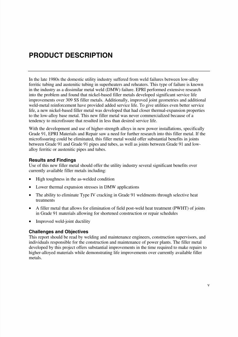
The weld test plates for the mechanical tests were all made of CMn steel that had been buttered
with two layers using the same batch of consumables under test. The test plates were either0.5 in. (12.7 mm) or 0.75 in. (19 mm) thick, depending on the testing to be carried out, and useda backing bar. For the configuration for the mechanical test plates, see Figures 2-2 and 2-3. The
test plates for the hot tensile test were 0.75 in. (19 mm) thick, and all the other testing was
carried out on 0.5 in. (12.7 mm) thick test plates. All of the welding was carried out using dc+polarity and ~120 A with a weld bead sequence using two beads per layer. No preheat was
applied, and a maximum interpass temperature of 300°F (150°C) was used. Apart from the single
test carried out in the normalised and tempered condition, all of the mechanical testing wascarried out in the as-welded condition.
1 in. = 25.4 mm
Figure 2-2Dimensions of the Test Plates

8/11/2019 Development of Advanced Methods for Joining Low-Alloy Steels
http://slidepdf.com/reader/full/development-of-advanced-methods-for-joining-low-alloy-steels 25/58
EPRI Licensed Material
Experimental Procedure
2-5
1 in. = 25.4 mm
Figure 2-3Schematic Showing the Bead Sequence
2.3.2 Ambient Temperature Tests
The dissimilar weld metal under development is intended for elevated temperature service, but alimited amount of mechanical testing was carried out at room temperature. Tests carried outincluded:
• Tensile test
• Hardness test
• Charpy test
• Side-bend test
The test plates for the hot-tensile tests were also radiographed and assessed against appropriatestandards.
The ambient temperature tensile test was carried out according to British Standard Euronorm(BS EN) 10002-1:1990 using an 8-mm (0.3-in.) diameter specimen machined longitudinallyfrom an all weld metal test plate. Hardness measurements were carried out according to BS ENISO 6507-1:1998 using the Vickers method (10 kg [22.1 lb] load) with a diamond pyramidindentor. The Charpy specimens were taken from the weld centerline, mid-thickness, andnotched through-thickness, and were tested according to BS EN 10045-1:1990. The transverseside-bend test specimens had the cap and weld backing machined flush to produce a specimen offull plate thickness ~0.5 in. (~12.5 mm) by 0.4 in. (10 mm) thick. The specimens were then bentthrough 180° over a 4T diameter former (1.6 in. [40 mm]).
2.3.3 Elevated Temperature Tests
Two types of high-temperature tests were carried out, hot-tensile tests (American Society forTesting and Materials [ASTM] E21) and short-term stress-rupture tests (aiming for failure in 100hours). All of the high-temperature testing was carried out at 1100°F (593°C). This is the same

8/11/2019 Development of Advanced Methods for Joining Low-Alloy Steels
http://slidepdf.com/reader/full/development-of-advanced-methods-for-joining-low-alloy-steels 26/58
EPRI Licensed Material
Experimental Procedure
2-6
temperature at which previous stress-rupture tests were carried out [1], and it is within thepotential service temperature range for P91. There were two reasons for carrying out the hot-tensile tests:
1. To obtain information on the high-temperature proof stress of the weld metals so that a
suitable load for the stress-rupture tests could be estimated
2. Recognizing the previously observed indications on the gauge length of short-term stress-rupture specimens to see if the hot tensile test proved to be more discriminating than our newmicrofissure test when ranking the microfissuring tendencies of the weld metals
The hot tensile tests were carried out according to ASTM A370 and ASTM E21 using aspecimen of ~0.5-in. (~12.7-mm) gauge diameter, machined longitudinally from each all weldmetal test plate. Note that one of the hot tensile tests (batch D724) was tested according to BSEN 10002-5 using a 0.2-in. (5-mm) diameter specimen.
Stress-rupture tests were carried out according to ASTM E139 on longitudinal all weld metalsamples. All of the stress-rupture tests were carried out at 593°C (1100°F), and the load for thefirst set of tests (43 ksi [297 MPa]) was selected to be about 90–95% of the hot tensile proofstress, aiming for failure to occur in a relatively short time. Based on the hot tensile propertiesand the results of the first set of stress-rupture tests, a second series of tests will be carried out.
2.3.4 N+T
One of the proposed applications for the dissimilar weld metal was for the buttering of weldpreparations in P91 components that would then be N+T to allow as-welded joints to be madeon-site. As a preliminary check to establish whether there might be an undesirable loss of weld-
metal strength in this application, a hot tensile test was carried out on a representative batch ofelectrodes following a N+T heat treatment of 1940°F (1060°C) for one hour with an air cool,followed by 1400°F (760°C) for two hours and an air cool. This N+T heat treatment was selectedas being typical of that applied to P91 base material.

8/11/2019 Development of Advanced Methods for Joining Low-Alloy Steels
http://slidepdf.com/reader/full/development-of-advanced-methods-for-joining-low-alloy-steels 27/58
EPRI Licensed Material
3-1
3RESULTS AND DISCUSSION
3.1 Microfissuring
Over 55 different chemical compositions of filler metals were manufactured and evaluated formicrofissuring tendencies. These different alloys controlled the addition of 16 different elementsand measured two different elements including: C, Si, Mn, P, S, Cr, moly, Fe, vanadium (V),tungsten (W), Cu, Al, cobalt (Co), Nb, tin (Sn), and Ni. Before detailing the effects ofcomposition on microfissuring, general comments on the microfissuring assessment technique
are presented.
3.1.1 Method of Microfissuring Assessment
A wide range of microfissuring susceptibility was observed, and for the purposes of evaluation,an MI was allocated that allowed the experimental batches to be divided into five groups, rankedfrom 1 to 5, where 1 had a very low incidence of microfissuring and 5 had extensivemicrofissuring. In some cases, fissures propagated almost through the full depth of the buildup.The allocation of a batch into a particular MI level was judged by eye, based on the generalextent and amount of microfissuring seen in the dye-penetrant test. Examples of the extent ofmicrofissuring found on the longitudinal face of the test buildup specimens at the different MI
levels when ground and dye-penetrant tested are shown in Figures 3-1 through 3-4.
Note: Owing to the penetrant bleed-out and contrast, the pictures in Figures 3-1 through 3-4 donot show the full extent of the microfissuring in the worst-case examples.

8/11/2019 Development of Advanced Methods for Joining Low-Alloy Steels
http://slidepdf.com/reader/full/development-of-advanced-methods-for-joining-low-alloy-steels 28/58
EPRI Licensed Material
Results and Discussion
3-2
Figure 3-1D694 (MI = 1) - Dye Penetrant Examination - Schematic of the Original Dye-Penetrant Test
Figure 3-2D717 (MI = 2) - Dye-Penetrant Examination - Schematic of the Original Dye-Penetrant Test

8/11/2019 Development of Advanced Methods for Joining Low-Alloy Steels
http://slidepdf.com/reader/full/development-of-advanced-methods-for-joining-low-alloy-steels 29/58
EPRI Licensed Material
Results and Discussion
3-3
Figure 3-3D929 (MI = 2) - Dye-Penetrant Examination - Schematic of the Original Dye-Penetrant Test
Figure 3-4D930 (MI = 5) - Dye-Penetrant Examination - Schematic of the Original Dye-Penetrant Test
The MI versus composition plots were all based on analyses taken from weld pads. To ensure
that these analyses were representative of those found in the MI test buildups, a check analysiswas carried out on one of the MI buildups. The C was slightly higher in the MI buildup, althoughthis was not considered to be significant.
From the evidence of testing, we concluded that the unique technique used discriminateddifferences in MI much more easily than by examining the incidence of fissuring in the post-tested gauge length of hot/ambient tensile specimens, and required no special test rigs unlike

8/11/2019 Development of Advanced Methods for Joining Low-Alloy Steels
http://slidepdf.com/reader/full/development-of-advanced-methods-for-joining-low-alloy-steels 30/58
EPRI Licensed Material
Results and Discussion
3-4
fissure-bend tests. No doubt, there may be variables in the test procedure that should beexamined in more detail, but such work falls outside the scope of the present project.
Our microfissure test is suspected to be more severe and searching than the fissure-bend test.Unlike more elaborate instrumented techniques, such as transvarestraint, both tests depend on
passive or self-restraint. In the fissure-bend test, the machined test weld is subjected to a smalltransverse bending operation to open and reveal any actual or incipient HAZ microfissures;whereas, in our test, it is believed that fissuring tendencies are amplified to some extent by anumber of factors intrinsic to the test. Among these are:
• Contraction stresses upon solidification and cooling are practically confined to thelongitudinal orientation.
• The restricted interval of one bead depth between stacked HAZs provides a short propagationpath for fissures to link vertically between weld runs.
• Stacking provides cumulative residual stress helping to provoke fissuring.
Coupled with these factors, it is probably significant that the geometry and heat flow restricts thecurvature of susceptible primary columnar cell boundaries that are expected to nucleate and growupward through successive beads.
3.1.2 Influence of Composition on Microfissuring
Near the outset, it became clear that compositions closely resembling the original HFS6 werehighly susceptible to microfissuring, confirming observations made in the previous project.
However, as the test matrix was progressively extended and assessed, it was evident that in some
compositions microfissuring could be substantially brought under control.
Ignoring at this stage any interaction between the various alloying additions investigated, graphsillustrating the MI versus alloying additions were plotted to show the benefits of different alloys.Since these graphs show the effect of only a single alloying element, interactive effects for anumber of data points are concealed, so there is a considerable amount of scatter. Figures 3-5through 3-9 show some of the correlations between various chemical additions and the tendencyto microfissure.
Manganese was one of the deliberately varied alloy additions, but within the studied range, itsinfluence appeared to be minor with the possible exception of deleterious effects below about0.8% Mn when all compositions had high MIs (see Figure 3-5).

8/11/2019 Development of Advanced Methods for Joining Low-Alloy Steels
http://slidepdf.com/reader/full/development-of-advanced-methods-for-joining-low-alloy-steels 31/58
EPRI Licensed Material
Results and Discussion
3-5
Figure 3-5Microfissuring Index Plotted Against Manganese Content
In phase 2 of the alloy development, it became apparent that electrodes made using the same fluxbut on different core wires had a different microfissuring index. Batches of electrodes made onthe bimetallic-clad core wire were far more susceptible to microfissuring than batches madeusing the same flux covering on the alloyed-core wire. This can be clearly seen from the two
batches D688 (MI = 2) and D688 clad (MI = 4), where the only difference was the core wireused. The only apparent difference that could be found was in the P content of the two deposits,0.010% for D688 clad, but 0.006% for D688. This variation in P would not normally have beenconsidered significant, so a check was carried out by remaking the D688 electrode on the alloyedcore wire but deliberately adding P; this was batch D690 (P = 0.015%). The composition ofD690 was very similar to D688 apart from the P (0.015% instead of 0.006%), and this higher Pincreased microfissuring to the same level as D688 clad (MI increased from 2 to 4). As a resultof these findings in relation to the P content of the weld deposit being higher with electrodesmade on the bimetallic-core wire, most future work was concentrated on the alloyed-core wire.
However, some further batches were made on the bimetallic-core wire to see if the deleterious
effect of P could be overcome by varying the alloying additions. It was shown in further teststhat the deleterious effect of P could be reduced by careful control of the remaining composition.
There were some batches (D695 clad, D924, and D926) with higher phosphorus (≥ 0.010%) thatwere still rated with a good microfissuring index of 1 or 2, but these three batches all had carbon
≥ 0.10% and niobium ≥ 1.5%. Although it proved possible to reduce the deleterious effect ofphosphorus, a low level was generally still beneficial or at least desirable, even for the mostrobust compositions. For example, D924 (0.11% C-1.96% Nb-0.011% P) had a microfissuring

8/11/2019 Development of Advanced Methods for Joining Low-Alloy Steels
http://slidepdf.com/reader/full/development-of-advanced-methods-for-joining-low-alloy-steels 32/58
EPRI Licensed Material
Results and Discussion
3-6
rating of 2, but in the otherwise similar batch D923 (0.12% C-2.02% Nb-0.006% P), the MI wasimproved to 1. A plot for MI versus % P is shown in Figure 3-6.
Figure 3-6Microfissuring Index Plotted Against Phosphorus Content
Following the findings with respect to P, a batch was also made with a deliberate S addition tosee if this also increased the sensitivity to microfissuring. At the S level examined (0.006% inD691), there was no obvious increase in susceptibility to microfissuring (MI=2, as expected froma composition that would later be judged “sub-optimal”).
There was no deliberate attempt to investigate the effect of Si deoxidation on microfissuringsusceptibility, but two batches (D699 and C308) did have higher Si contents (0.54% and 0.62%).Although two batches are not sufficient proof, these batches with high Si were more susceptibleto microfissuring than would have been expected. It is difficult to make a complete judgementbecause batch D699 not only had high Si but also a borderline C level (0.065%) and belowoptimum Mn (0.44%). Figure 3-7 shows the MI plotted against Si, and apart from batches D699
and C308, with 0.54% and 0.62% silicon, there is no correlation over the range (~0.2–0.4%)tested. Similar plots for Ti and Al are shown in Figures 3-8 and 3-9, and again no conclusionswere drawn except that Ti and Al were not deleterious. Any apparent correlation was judged tobe the result of covariance arising from other more significant modifications.

8/11/2019 Development of Advanced Methods for Joining Low-Alloy Steels
http://slidepdf.com/reader/full/development-of-advanced-methods-for-joining-low-alloy-steels 33/58
EPRI Licensed Material
Results and Discussion
3-7
Figure 3-7
Microfissuring Index Plotted Against Silicon Content
Figure 3-8Microfissuring Index Plotted Against Titanium Content

8/11/2019 Development of Advanced Methods for Joining Low-Alloy Steels
http://slidepdf.com/reader/full/development-of-advanced-methods-for-joining-low-alloy-steels 34/58
EPRI Licensed Material
Results and Discussion
3-8
Figure 3-9
Microfissuring Index Plotted Against Aluminum Content
After comparing the effect of each chemical on the microfissuring tendencies of the filler metal,a microfissuring factor (MF) will be developed. An empirical MF formula will be developed thatwill account for compositional effects of each element and provide a quick calculation for the
microfissuring tendencies of each filler metal.
3.1.3 Metallography
The microfissuring test buildups for batches D930 (MI = 5), D929 (MI = 4), D717 (MI = 2), andD694 (MI = 1) were all sectioned. The metallography that was carried out supported the findingsof the dye-penetrant testing, although the microfissuring generally appeared to be more extensivethan in the dye-penetrant tests. All of the macrosections showed microfissures, but the trend wasthe same as seen in the dye-penetrant tests with cracking increasing as the MI increased. Theextent of cracking from the ground longitudinal surface of the microfissuring test buildups isshown in Figures 3-10 through 3-13. These are the same test faces that were dye-penetrant tested
(original magnification × 4, etched electrolytically in aqueous sulphuric acid).

8/11/2019 Development of Advanced Methods for Joining Low-Alloy Steels
http://slidepdf.com/reader/full/development-of-advanced-methods-for-joining-low-alloy-steels 35/58
EPRI Licensed Material
Results and Discussion
3-9
Figure 3-10
D694 (MI = 1)
Figure 3-11D717 (MI = 2)

8/11/2019 Development of Advanced Methods for Joining Low-Alloy Steels
http://slidepdf.com/reader/full/development-of-advanced-methods-for-joining-low-alloy-steels 36/58
EPRI Licensed Material
Results and Discussion
3-10
Figure 3-12D929 (MI = 4)
Figure 3-13D930 – Within HFS6 Analysis Limits (MI = 5)
In the microsections, it was difficult to determine exactly where the interface between the finalbead and the underlying bead was located. Therefore, it was difficult to see if cracking stopped atthe interface between the two beads. There were certainly no surface-breaking cracks, but it didappear that some cracks extended into the final bead. It is proposed that some of the fissures inthe final run may be caused by the “wash” of weaving when the bead was deposited, effectively
resulting in parts of the final bead undergoing some reheating. Microfissure stopping in the finalbead is shown in Figures 3-14 and 3-15 (original magnification × 50, etched electrolytically inaqueous sulphuric acid).

8/11/2019 Development of Advanced Methods for Joining Low-Alloy Steels
http://slidepdf.com/reader/full/development-of-advanced-methods-for-joining-low-alloy-steels 37/58
EPRI Licensed Material
Results and Discussion
3-11
Figure 3-14D694 – Crack Stops About 0.5 mm (0.02 in.) Before the Top of the Final Bead (Note that theBead Surface Can Be Seen in the Top Right Corner). This Cracking Appears to Extend intothe Final Bead. It Is Proposed That This May Have Been Caused by the “Wash” of WeavingWhen the Bead Was Deposited, Resulting in Parts of the Final Bead Undergoing SomeReheating.
8/11/2019 Development of Advanced Methods for Joining Low-Alloy Steels
http://slidepdf.com/reader/full/development-of-advanced-methods-for-joining-low-alloy-steels 38/58
EPRI Licensed Material
Results and Discussion
3-12
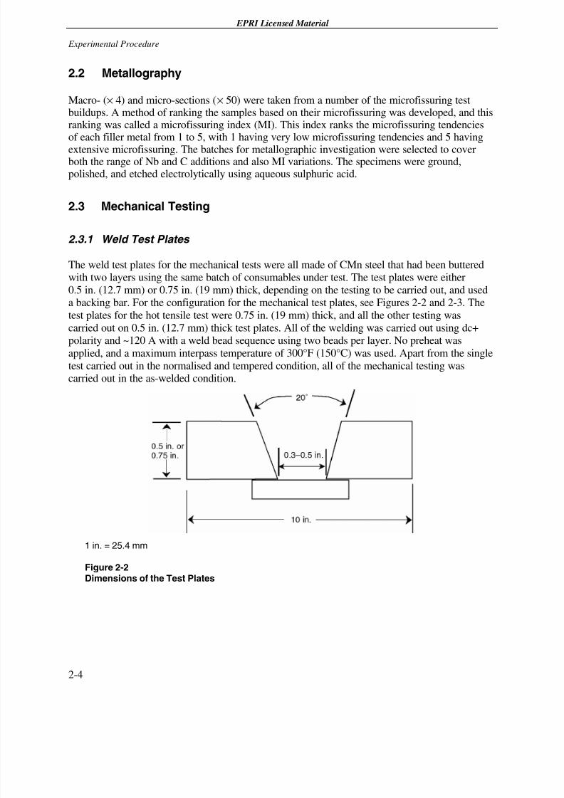
Figure 3-15D929 – Crack Stops About 1 mm (0.4 in.) Before the Top of the Final Bead. The
Microfissures Do Appear to Follow a Primary Grain Boundary.
Batches D930 (0.03% C-0.04% Nb), D929 (0.06% C-1.2% Nb), D717 (0.07% C-0.8% Nb), andD694 (0.10% C-1.5% Nb) showed a variation not only in MI but also in alloy content. Thehigher addition of Nb and C was evident from the microstructure, with batches D929, D717, and
D694 all showing an interdendritic eutectic that was not as evident in batch D930. Micrographsshowing the formation of an interdendritic Nb-C eutectic with the alloying addition of Nb and C
are shown in Figure 3-16 and 3-17 (original magnification × 50, etched electrolytically inaqueous sulphuric acid).

8/11/2019 Development of Advanced Methods for Joining Low-Alloy Steels
http://slidepdf.com/reader/full/development-of-advanced-methods-for-joining-low-alloy-steels 39/58
EPRI Licensed Material
Results and Discussion
3-13
Figure 3-16D930 (HFS6) – No Deliberate Nb and C
Figure 3-17D694 – 1.5% Nb and 0.010% C

8/11/2019 Development of Advanced Methods for Joining Low-Alloy Steels
http://slidepdf.com/reader/full/development-of-advanced-methods-for-joining-low-alloy-steels 40/58
EPRI Licensed Material
Results and Discussion
3-14
There was no extensive evaluation of the microstructure at the interface between the weld metaland ferritic steels, but Figures 3-18 and 3-19 show the boundaries between the deposit D694 andthe CMn steel base material used for the buildup (etched electrolytically in aqueous sulphuricacid). This does not show any difference in microfissuring tendency between the diluted weldmetal and the all weld metal composition.
Figure 3-18
Macro Showing Transverse Section of Test Buildup (Original Magnification ×××× 4)
Figure 3-19Micrograph Showing Detail from Above Macro, CMn Base Material at Bottom (Original
Magnification ×××× 50)

8/11/2019 Development of Advanced Methods for Joining Low-Alloy Steels
http://slidepdf.com/reader/full/development-of-advanced-methods-for-joining-low-alloy-steels 41/58
EPRI Licensed Material
Results and Discussion
3-15
Late in the optimization phase of this project, a Japanese paper came to light that was directlyrelevant to the present work [2]. The Japanese study concerned the development of improved gastungsten arc welding (GTAW) filler for Invar (Fe-0.003% C-0.2% Mn-0.03% Si-0.001%S-0.005% P-36% Ni), one of the nearest relatives to HFS6 that has an additional 10% Ni-9%Cr-2% Mo. The history of “matching” fillers for Invar is littered with the microfissure-riddledcorpses of promising compositions that evidently died on the job.
Microfissuring (described in [2] as ductility dip cracking as a consequence of grain boundarysliding) was confirmed when using matching filler in a 9.5 mm (0.37 in.) Invar butt weld but wassuppressed with the addition of 0.2% C and 0.8-1.6% Nb. The authors state that these additionschanged the microstructure from cellular with planar grain boundaries to cellular dendritic withzig-zag boundaries that resisted cracks caused by sliding. The NbC eutectic was also said toincrease the interphase area, reducing the local concentration of deleterious segregated S (despiteS < 0.001% being reported). However, with filler having 0.23% C-0.8% Nb, fissuring reappearedin the lower part of welds owing to dilution below the optimum required, so 0.23% C-1.6% Nbfiller was necessary for the root and first few runs.
As noted previously, the modified HFS6 appears to have satisfactory tolerance to dilution, butthis aspect should be kept in mind during future studies.
3.2 Ambient Temperature Tests
3.2.1 Tensile Tests
The room temperature tensile properties of batch D724 are given in Table 3-1. Batch D724 wasselected for testing on the basis of it being representative of a batch with a composition withinthe optimum analysis. The strength was much as would be expected from a high Ni-alloy
austenitic weld metal. It exceeded the tensile requirements for P11/P22 base material given inAmerican Society of Mechanical Engineers (ASME) SA-335 but does not meet the tensilerequirements for P91. The strength of the weld metal would be more than adequate for CrMo tostainless steel dissimilar joints, but, for joints in P91 to P91, it may require further evaluation.

8/11/2019 Development of Advanced Methods for Joining Low-Alloy Steels
http://slidepdf.com/reader/full/development-of-advanced-methods-for-joining-low-alloy-steels 42/58
EPRI Licensed Material
Results and Discussion
3-16
Table 3-1Room Temperature Tensile Properties of Batch D724
Elongation%
Hardness, HV(10kg)
Batch0.2%Proof
ksi (MPa)
UltimateTensile
Strength
(UTS)ksi (MPa)
4d 5d
Reduction ofArea
% Cap Mid
D724 52 (359) 81.5 (562) 34 32 49 160 181
A335 P11/P22 30 (205) 60 (415) 14/22 - - - -
A335 P91 60 (415) 85 (585) 20 - - - -
BS EN 10222-2X10CrMoVNb9-1
65.3 (450)91.4–105.9(630–730)
- 17/19 - - -
The possibility that room-temperature tensile properties of a Ni-based weld metal may not matchthose of P91 was raised during the contract negotiations. It is not thought that the lower roomtemperature strength of the weld metal will prevent it being used, because at elevatedtemperature the weld metal matches the P91 strength (see Section 3.3.1). However, this wouldneed a new code approach with respect to carrying out weld procedure qualifications, which arenormally dependent on weld metals matching base material strength. Therefore, this issue wasnot investigated further during this part of the project.
There are numerous different microfissuring tests and assessment methods. One evaluationmethod that has been proposed is to examine the gauge surface of a fractured tensile specimen.The gauge length of the fractured tensile carried out on D724 had a rippled surface showingmany strain marks and three indications that had opened on the surface perpendicular to the
longitudinal axis of the specimen. This would appear to be an indication that there were stillsome microfissures in the weld metal. Unfortunately, we do not have any reference mark on thetensile specimen to be able to determine its orientation relative to the weld and hence theorientation of the indications on the specimen surface. It should be possible to determine theorientation by sectioning and etching the stub of the tensile specimen, but this was not carriedout in this project. The indications were not random but were approximately aligned along oneside of the tensile specimen, so all of the indications were in the same approximate orientationrelative to the weld.
3.2.2 Charpy Tests
Charpy tests were carried out on batch D724, which was representative of the experimentalbatches investigated. At 68°F (20°C) an average of 60 ft-lb (82 J) in the as-welded condition wasconsidered to be more than adequate for any of the intended applications. See Table 3-2 for theindividual Charpy values and lateral expansion.

8/11/2019 Development of Advanced Methods for Joining Low-Alloy Steels
http://slidepdf.com/reader/full/development-of-advanced-methods-for-joining-low-alloy-steels 43/58
EPRI Licensed Material
Results and Discussion
3-17
Table 3-2Room Temperature Impact Properties of Batch D724
Test Temperature°F (°C)
Charpy Energyft-lb (J)
Lateral Expansionmils (mm)
68 (20) 67, 58, 57 (91, 78, 77) 56, 49, 48 (1.41, 1.23, 1.22)
3.2.3 Side-Bend Tests
Three transverse side-bend tests were carried out on batch D724, which had a microfissuringindex of 1 determined from the alloying-development phase. If assessed according to the criteriaof QW-163 ASME IX, then all of the bend tests would have been considered acceptable,although one specimen did show two small indications that were both <1.0 mm (<0.04 in.) long(one at the corner of the specimen). What was of interest was that all three specimens showedindications on the non-test faces of the bend specimens (that is: what would have been the cap orroot face) in the longitudinal orientation. One of these was 3 mm (not quite 0.125 in.), and theothers
2 × 1.5 mm (0.0625 in.) and 1 mm (<0.0625 in.). This would appear to indicate that a cap orroot-face bend test may be more likely to show up indications, although the ASME IXqualification carried out during the earlier project [1] does not support this, there only being oneindication noted on a face-bend specimen despite later fissure bend tests indicating “… arelatively high fissuring tendency.”
3.2.4 Radiography Tests
The test plates welded for the hot tensile tests using batches D922-D933 were all radiographed.
The occasional gas pore was present, but at acceptable levels. The only batch that wasunacceptable was D928, which had scattered porosity throughout the weld (see Table 3-3 for allcomments).

8/11/2019 Development of Advanced Methods for Joining Low-Alloy Steels
http://slidepdf.com/reader/full/development-of-advanced-methods-for-joining-low-alloy-steels 44/58
EPRI Licensed Material
Results and Discussion
3-18
Table 3-3Radiographic Report Comments
Batch Comments ASME IX
D922 A few gas pores up to 2 mm diameter noted. Pass
D923 A few gas pores noted. Pass
D924 A few gas pores noted. Pass
D925 No evidence seen of any internal flaws. Pass
D926 A few gas pores noted. Pass
D927 A few random pores noted. Pass
D928 Scattered porosity full weld length. Fail
D929 Occasional gas pores noted at random. A crack ~3 mm long noted. Pass *
D930 A few random pores noted. Pass
D931 No evidence of any internal flaws. Pass
D932 Occasional random gas pores noted. Pass
D933 Occasional random gas pores noted. Pass
* According to ASME IX QW191.2.2 Acceptance Criteria.
The porosity in batch D928 was attributed to the nitrogen (N) addition that had been made
through the flux covering, which raised the typical N from about 0.03% to about 0.05%.Although the weld showed extensive porosity, this had no influence on the hot strength. Thenitrogen actually increased the strength. The microfissure test buildup made using batch D928showed a few crack-like indications and was allocated an MI of 2, but no evidence of porositywas found when the dye-penetrant test was carried out.
3.3 Elevated Temperature Tests
3.3.1 Hot Tensile (As-Welded) Tests
The hot tensile tests were all carried out at 593°C (1100°F). The experimental batches testedshowed quite a variation in hot strength ranging from 35.5 ksi (245 MPa) to 50.3 ksi (347 MPa)0.2% proof stress; and 52.7 ksi (363 MPa) to 76.9 ksi (530 MPa) ultimate tensile strength. Allresults are given in Table 3-4.

8/11/2019 Development of Advanced Methods for Joining Low-Alloy Steels
http://slidepdf.com/reader/full/development-of-advanced-methods-for-joining-low-alloy-steels 45/58
EPRI Licensed Material
Results and Discussion
3-19
Table 3-4Hot Tensile Results Carried Out at 1100°F (593°C)
Batch0.2% Proof
1
ksi (MPa)UTS
ksi (MPa)4d Elongation
%Reduction of Area
%Proof/UTS
RatioMI
2
D724 3 42 (290) 61 (421) 13.5 26 0.689 1
D922 48.5 (334) 75.9 (523) 28 35 0.639 1
D923 48.0 (331) 74.4 (513) 24 30 0.645 1
D924 46.2 (319) 70.4 (485) 15.5 21.3 0.656 2
D925 49.5 (341) 76.5 (527) 21 24 0.647 2
D926 46.6 (321) 70.9 (489) 17.5 29 0.657 2
D927 46.3(319) 72.4 (499) 26.5 39 0.640 1
D928 50.3 (347) 76.9 (530) 23.5 30 0.654 2
D929 43.5 (300) 63.0 (434) - 25 0.690 4
D930 36.8 (254) 52.7 (363) 14.5 24 0.698 5
D931 36.9 (254) 60.4 (416) 29.5 39 0.611 5
D932 35.5 (245) 54.4 (375) 18.5 35.3 0.653 5
D933 35.6 (245) 60.5 (417) 34 42.3 0.588 5
1. 0.2% proof stress requirement for X10CrMoVNb9-1 (P91) in BS EN 10222-2:2000 is 211MPa(30.6ksi) at 593°C (1100°F).
2. MI = microfissuring index (1 = no microfissuring, 5 = extensive microfissuring).
3. The test on batch D724 was carried out on a specimen of 5 mm (~0.2 in.) diameter whereas all theother tests were on a specimen of ~12.7 mm (0.5 in.) diameter.
When plotted, it could be shown that the 0.2% proof stress and UTS both increased withincreasing C and Nb content (see Figures 3-20 and 3-21). The relationship with Nb was linear upto a certain level, above which the strength showed no further increase. The batch D928, whichhad a higher strength than its Nb and C content would have predicted, had an N addition. The Napparently had a strengthening effect on the austenitic matrix, which resulted in the highest
strength considering its C and Nb levels. The extensive porosity found in D928 would make theuse of N additions for strengthening unacceptable.

8/11/2019 Development of Advanced Methods for Joining Low-Alloy Steels
http://slidepdf.com/reader/full/development-of-advanced-methods-for-joining-low-alloy-steels 46/58
EPRI Licensed Material
Results and Discussion
3-20
1 ksi = 6.8940092 MPa
Figure 3-20Hot Strength (1100°F/593°C) Variation with Alloy Content – Carbon

8/11/2019 Development of Advanced Methods for Joining Low-Alloy Steels
http://slidepdf.com/reader/full/development-of-advanced-methods-for-joining-low-alloy-steels 47/58
EPRI Licensed Material
Results and Discussion
3-21
1 ksi = 6.8940092 MPa
Figure 3-21Hot Strength (1100°F/593°C) Variation with Alloy Content - Niobium
The tensile strength and proof stress achieved with the batches containing Nb and C all exceedthe requirements of P91 base material at 1100°F (593°C). Even though the dissimilar weld metaldoes not meet the room temperature strength requirement of P91 (see section 3.2.1), it will matchthe P91 base material strength at typical operating temperatures. For example, the batches withNb and C additions comfortably exceed the requirement in BS EN 10222-2:2000 for theX10CrMoVNb9-1 grade (P91) of a minimum 0.2% proof stress at 1100°F (593°C) of 30.6 ksi(211 MPa).
Table 3-5 and Figure 3-22 show a comparison of the room temperature and elevated temperature(1100°F/593°C) tensile properties of batch D724. These results show that over this temperaturerange there is only about a 20–25% drop in strength compared to the 30–50% drop seen forferritic steels. This comparatively low drop in strength means that although the weld metal does
not match the room temperature strength of P91, it exceeds its strength at 1100°F (593°C).

8/11/2019 Development of Advanced Methods for Joining Low-Alloy Steels
http://slidepdf.com/reader/full/development-of-advanced-methods-for-joining-low-alloy-steels 48/58
EPRI Licensed Material
Results and Discussion
3-22
Table 3-5Comparison of Room and Elevated Temperature Strength for Batch D724
Temperature°F (°C)
0.2% Proofksi (MPa)
UTSksi (MPa)
4d Elongation%
Reduction of Area%
68 (20) 52 (359) 81.5 (562) 34 49
1100 (593) 42 (290) 61 (420) 13.5 26
Figure 3-22Strength Versus Temperature for Batch D724
There was quite a variation in 4D elongation (15–34%) and reduction of area (21–42%), butthere was no apparent correlation between elongation/reduction of area and MI. There was anapproximate correlation between MI and indications on the surface of the fractured tensilespecimens (see Table 3-6). When there were indications on the tensile specimens, they were not
randomly located around the circumference of the specimen, but were normally aligned alongone side of the specimen, and sometimes along sides at 90° to each other.

8/11/2019 Development of Advanced Methods for Joining Low-Alloy Steels
http://slidepdf.com/reader/full/development-of-advanced-methods-for-joining-low-alloy-steels 49/58
EPRI Licensed Material
Results and Discussion
3-23
Table 3-6Comparison of MI Ranking and the Surface Indications on the Gauge Length of theFractured Hot Tensile Specimens
Batch MI Tensile Ranking Comments
D922 1 1 One band with very few indications.
D923 1 1 One band with very few indications.
D924 2 2 Two bands of indications at 180° to each other.
D925 2 2 Two bands of indications at 180° to each other.
D926 2 3 Four bands of indications at 90° to each other.
D927 1 3 One major band of indications.
D928 2 2 Two bands of indications at 180° to each other.
D929 4 4One major band of indications, two minor bands at 90° &180° to the major band.
D930 5 5One major band of indications, two minor bands at 90° to themajor band.
D931 5 4 Two bands of indications at 90° to each other.
D932 5 2 Two minor bands at 180° to each other.
D933 5 5 One major band of indications and a minor band at 90° to it.
Two of the batches exhibiting low elongation and reduction of area values had higher P contents(D924 and D926), but there was not really enough data to be sure if this was directly related tothe presence of P.
Four batches were made (D930-D933) which were based on the HFS6 composition (D930) withvarying levels of boron (B). There were two reasons for examining small B additions:
1. It has been credited with improving hot ductility (including creep performance).
2. It has also been suggested it improves resistance to ”ductility dip” cracking, possibly bysuppressing grain boundary migration associated with this form of microfissuring (in contrastto microfissuring due to grain boundary liquation, where B would be detrimental).
It had been hoped that these benefits might be obtained in the HFS6 base composition withouthaving to resort to additional C and Nb. While there was no benefit to microfissuring (all had anMI of 5), the effect of B on hot tensile properties was inconclusive because, although it didappear to have a beneficial effect on the elongation, it was not linear. The HFS6 (D930) batchwithout B had the second lowest elongation at 15%, but as B was added (9 ppm, 19 ppm, and27 ppm) the 4d elongation increased but showed no obvious trend: 30% to 19% to 34% as

8/11/2019 Development of Advanced Methods for Joining Low-Alloy Steels
http://slidepdf.com/reader/full/development-of-advanced-methods-for-joining-low-alloy-steels 50/58
EPRI Licensed Material
Results and Discussion
3-24
Boron was increased. Batch D932 (with 19 ppm B) was one of the batches that showed a poorcorrelation between the indications on the surface of the tensile specimen gauge length and theMI.
The proof to tensile ratio (Rp0.2%
/Rm) when plotted (see Figure 3-23), showed a correlation to the
elongation and reduction of area, but again no obvious correlation with the microfissuring index.
Figure 3-23Proof Stress/UTS Ratio Versus Ductility for Hot Tensile (1100°F/593°C) Tests
Another interesting point highlighted by the hot-tensile results is relevant to the interpretationsdrawn from the stress-rupture tests carried out in the earlier project [1]. The all-weld metalstress-rupture tests carried out in the earlier work with batch HFS6 were tested at 1100°F(593°C) with a load of 35 ksi (241 MPa). From the hot tensile test that was carried out on batchD930 (which was within the HFS6 composition limits), it was concluded that 35 ksi (241 MPa)was nearly equal to the proof stress of this composition at 1100°F (593°C). Batch 930 had a
0.2% proof stress of 36.8 ksi (254 MPa) so a load of 35 ksi (241 MPa) would be in the region of95% of the 0.2% proof stress at 1100°F (593°C), so it is perhaps not surprising that the times torupture were only 9–15 hours. It would appear that the load used for these earlier tests was morelikely to be the main reason for the short rupture times, rather than the presence of anymicrofissures. The cross-weld tests were done at a lower stress of 21.7 ksi (150 MPa) and ran for446–504 hrs, but as they failed at interfaces and not weld metal, perhaps the all weld strengthwas assumed to be greater than it was in reality. In addition, there was the issue of degradationinfluenced by microfissuring.

8/11/2019 Development of Advanced Methods for Joining Low-Alloy Steels
http://slidepdf.com/reader/full/development-of-advanced-methods-for-joining-low-alloy-steels 51/58
EPRI Licensed Material
Results and Discussion
3-25
3.3.2 Hot Tensile (N+T) Tests
Batch D925, which had previously been subject to a hot tensile test and produced 49.5 ksi(341 MPa) 0.2% proof stress, was subject to another all weld metal hot tensile test, but followingan N+T heat treatment. Following an N+T heat treatment, the 0.2% proof stress at 1100°F
(593°C) was reduced to 33 ksi (226 MPa); details of results are given in Table 3-7. This equatesto a reduction in proof stress of about a third following N+T and a reduction in UTS of about onesixth. The N+T heat treatment was selected because it was typical of that applied to P91 basematerial (normalize: 1940°F/1060°C for one hour with an air cool + temper: 1400°F/760°C fortwo hours with an air cool).
Table 3-7Comparison of As-Welded and N+T Hot Strength (1100°F [593°C]) of Batch D925
Condition0.2% Proofksi (MPa)
UTSksi (MPa)
4d Elongation%
Reduction of Area%
As-welded 49.5 (341) 76.5 (528) 21 24
N+T 33 (226) 63 (435) 24.5 33
N+T: 1940°F (1060°C)/1 hour AC + 1400°F (760°C)/2 hours AC
These properties were just in excess of the minimum 0.2% proof stress requirement of 211 MPa(30.6 ksi) at 593°C (1100°F) for P91 base material according to BS EN 10222-2:2000. Theseproperties may require further evaluation but they were considered satisfactory for initialstrength validation as a buttering layer subject to N+T.
3.3.3 Stress-Rupture Tests
Four batches (D927, D923, C269, and C273) were selected for initial stress-rupture tests,including one batch containing B (C273). The load for the first series of tests, 43 ksi (297 MPa),was about 90–95% of the proof stress of the weld metal at 1100°F (593°C) and was selected withthe intention of achieving a rupture life of around 100 hours. Table 3-9 shows the results of thestress-rupture tests currently available (Rev. 1 of the final report will include all results).

8/11/2019 Development of Advanced Methods for Joining Low-Alloy Steels
http://slidepdf.com/reader/full/development-of-advanced-methods-for-joining-low-alloy-steels 52/58
EPRI Licensed Material
Results and Discussion
3-26
Table 3-8Stress Rupture Results
Batch TestTemperature
°F (°C)
Loadksi (MPa)
4d RuptureElongation
%
RuptureReduction of
Area
%
Time toRuptureHours
D923 1100 (593) 43 (297) 8.8 33.2 154.75
D927 1100 (593) 43 (297) >150
C269 1100 (593) 43 (297) >150
C273 1100 (593) 43 (297) >150
The tests on batches D927, C269, and C273 are still running.

8/11/2019 Development of Advanced Methods for Joining Low-Alloy Steels
http://slidepdf.com/reader/full/development-of-advanced-methods-for-joining-low-alloy-steels 53/58

8/11/2019 Development of Advanced Methods for Joining Low-Alloy Steels
http://slidepdf.com/reader/full/development-of-advanced-methods-for-joining-low-alloy-steels 54/58

8/11/2019 Development of Advanced Methods for Joining Low-Alloy Steels
http://slidepdf.com/reader/full/development-of-advanced-methods-for-joining-low-alloy-steels 55/58
EPRI Licensed Material
5-1
5REFERENCES AND BIBLIOGRAPHY
5.1 References
1. Dissimilar Weld Failure Analysis and Development Program, Volume 9: Optimized Filler
Metal Development . EPRI, Palo Alto, CA: 1987. CS-4252.
2. S. Hongoh et al. “Multipass GTAW Process for Thick Joint of Fe-36% Ni Alloy,” IIW,Document IX-2022-02 (2002).
5.2 Bibliography
Bland, J. and Owczrski, W. A. “Arc Welding of a Ni-Cr-Fe (Inconel) Alloy for Nuclear PowerPlants.” Welding Journal, Welding Research Supplement, January 1961, pp. 22s–32s.
Carey, J. D. and McKittrick, G. F. “Control of Fissuring in Inconel by Regulating ProcessVariables.” Welding Journal, Welding Research Supplement, December 1962, pp. 529s–533s.
DuPont, J. N. and Robino, C. V. “The Influence of Nb and C on the SolidificationMicrostructures of Fe-Ni-Cr Alloys.” Scripta Materialia, Vol. 41, No. 4, 1999, pp. 449–454.
DuPont, J. N., Robino, C. V., and Marder, A. R. “Solidification & Weldability of Nb BearingSuperalloys.” Welding Journal, Welding Research Supplement, October 1998.
Lee, H. T. and Kuo, T. Y. “Effects of Nb on Microstructure, Mechanical Properties andCorrosion Behavior in Weldments of Alloy 690.” Science & Technology of Welding & Joining,Vol. 4, No. 4, 1999.
Lingren et al. “Method of Welding Austenitic Steel to Ferritic Steel with Filler Alloys.” UnitedStates Patent 4,703,885, November 1987.

8/11/2019 Development of Advanced Methods for Joining Low-Alloy Steels
http://slidepdf.com/reader/full/development-of-advanced-methods-for-joining-low-alloy-steels 56/58

8/11/2019 Development of Advanced Methods for Joining Low-Alloy Steels
http://slidepdf.com/reader/full/development-of-advanced-methods-for-joining-low-alloy-steels 57/58

8/11/2019 Development of Advanced Methods for Joining Low-Alloy Steels
http://slidepdf.com/reader/full/development-of-advanced-methods-for-joining-low-alloy-steels 58/58
© 2003 Electric Power Research Institute (EPRI), Inc.All rights
reserved.Electric Power Research Institute and EPRI are registered
Strategic Science and Technology Program
About EPRI
EPRI creates science and technology solutions for
the global energy and energy services industry. U.S.
electric utilities established the Electric Power
Research Institute in 1973 as a nonprofit research
consortium for the benefit of utility members, their
customers, and society. Now known simply as EPRI,
the company provides a wide range of innovative
products and services to more than 1000 energy-
related organizations in 40 countries. EPRI’s
multidisciplinary team of scientists and engineers
draws on a worldwide network of technical and
business expertise to help solve today’s toughest
energy and environmental problems.
EPRI. Electrify the World
SINGLE USER LICENSE AGREEMENT
THIS IS A LEGALLY BINDING AGREEMENT BETWEEN YOU AND THE ELECTRIC POWER RESEARCH
INSTITUTE,INC. (EPRI).PLEASE READ IT CAREFULLY BEFORE REMOVING THE WRAPPING MATERIAL.
BY OPENING THIS SEALED PACKAGE YOU ARE AGREEING TO THE TERMS OF THIS AGREEMENT. IF YOU DO NOT AGREE TO
THE TERMS OF THIS AGREEMENT,PROMPTLY RETURN THE UNOPENED PACKAGE TO EPRI AND THE PURCHASE PRICE WILL
BE REFUNDED.
1. GRANT OF LICENSE
EPRI grants you the nonexclusive and nontransferable right during the term of this agreement to use this package only for your ownbenefit and the benefit of your organization.This means that the following may use this package: (I) your company (at any site owned
or operated by your company);(II) its subsidiaries or other related entities;and (III) a consultant to your company or related entities,
if the consultant has entered into a contract agreeing not to disclose the package outside of its organization or to use the package for
its own benefit or the benefit of any party other than your company.
This shrink-wrap license agreement is subordinate to the terms of the Master Utility License Agreement between most U.S. EPRI
member utilities and EPRI.Any EPRI member utility that does not have a Master Utility License Agreement may get one on request.
2. COPYRIGHT
This package, including the information contained in it, is either licensed to EPRI or owned by EPRI and is protected by United States
and international copyright laws.You may not, without the prior written permission of EPRI, reproduce, translate or modify this
package, in any form,in whole or in part, or prepare any derivative work based on this package.
3. RESTRICTIONS
You may not rent,lease, license, disclose or give this package to any person or organization, or use the information contained in this
package, for the benefit of any third party or for any purpose other than as specified above unless such use is with the prior written
permission of EPRI.You agree to take all reasonable steps to prevent unauthorized disclosure or use of this package. Except as specified
above, this agreement does not grant you any right to patents, copyrights, trade secrets, trade names, trademarks or any other
intellectual property, rights or licenses in respect of this package.
4.TERM AND TERMINATION
This license and this agreement are effective until terminated.You may terminate them at any time by destroying this package. EPRI has
the right to terminate the license and this agreement immediately if you fail to comply with any term or condition of this agreement.
Upon any termination you may destroy this package, but all obligations of nondisclosure will remain in effect.
5. DISCLAIMER OF WARRANTIES AND LIMITATION OF LIABILITIES
NEITHER EPRI,ANY MEMBER OF EPRI,ANY COSPONSOR,NOR ANY PERSON OR ORGANIZATION ACTING ON BEHALF
OF ANY OF THEM:
(A) MAKES ANY WARRANTY OR REPRESENTATION WHATSOEVER, EXPRESS OR IMPLIED,(I) WITH RESPECT TO THE USE
OF ANY INFORMATION,APPARATUS, METHOD,PROCESS OR SIMILAR ITEM DISCLOSED IN THIS PACKAGE, INCLUDING
MERCHANTABILITY AND FITNESS FOR A PARTICULAR PURPOSE, OR (II) THAT SUCH USE DOES NOT INFRINGE ON OR
INTERFERE WITH PRIVATELY OWNED RIGHTS, INCLUDING ANY PARTY’S INTELLECTUAL PROPERTY, OR (III) THAT THIS
PACKAGE IS SUITABLE TO ANY PARTICULAR USER’S CIRCUMSTANCE; OR
(B) ASSUMES RESPONSIBILITY FOR ANY DAMAGES OR OTHER LIABILITY WHATSOEVER (INCLUDING ANYCONSEQUENTIAL DAMAGES, EVEN IF EPRI OR ANY EPRI REPRESENTATIVE HAS BEEN ADVISED OF THE POSSIBILITY OF
SUCH DAMAGES) RESULTING FROM YOUR SELECTION OR USE OF THIS PACKAGE OR ANY INFORMATION,APPARATUS,
METHOD,PROCESS OR SIMILAR ITEM DISCLOSED IN THIS PACKAGE.
6. EXPORT
The laws and regulations of the United States restrict the export and re-export of any portion of this package, and you agree not to
export or re-export this package or any related technical data in any form without the appropriate United States and foreign
government approvals.
7. CHOICE OF LAW
This agreement will be governed by the laws of the State of California as applied to transactions taking place entirely in California
between California residents.
8. INTEGRATION
You have read and understand this agreement, and acknowledge that it is the final, complete and exclusive agreement between you
and EPRI concerning its subject matter,superseding any prior related understanding or agreement. No waiver,variation or different
terms of this agreement will be enforceable against EPRI unless EPRI gives its prior written consent,signed by an officer of EPRI.