Embed Size (px)
Citation preview

22nd CAD-FEM Users’ Meeting 2004 International Congress on FEM Technology with ANSYS CFX & ICEM CFD Conference November 10-12, 2004, International Congress Center Dresden, Germany
Development of a window cooling for high temperature solar receivers
Ralf Uhlig, Marc Röger
German Aerospace Center (DLR), Institute of Technical Thermodynamics, Stuttgart, Germany
Summary
ANSYS/FLOTRAN had been used to calcualte the air flow in a gap between two quartz glass windows. This was done to design a cooling system for high temperature solar receivers, which are used to convert concentrated sunlight into high temperature heat. The most important thermal influences as radiation exchange between the windows and the absorber as well as the radiation to space of the pressure window had been considered. With a 2D axially symmetric parametric modell the CPU time was small enough to calculate severall varitations. The aim was to find out the best geometry for the cooling window for reaching the lowest possible glass temperatures by an minimum cooling mass flow and by adherence the possible pressure drop of the cooling system. The calculations showed that the best result could be reached by giving a swirl (around the middle axis) to the cooling flow. Therefore a special flange was designed for an uniform distribution and to give the swirl to the cooling flow. After manufactoring of the cooling window, the window was measured on a 3D measurement machine and the geometrie in the CFD modell was aligned to the real geometrie. Further calculations with the “real” gemetrie showed that the pressure drop will be less and the temperatures in the windows will be a little higher then in the design geometrie.The high temperature module was tested together with an gas turbine at the Plataforma Solar de Almeria (PSA) in south Spain. The first evaluation of the measurements showed that the cooling works well. The cooling flow works like CFD calculation predicted. Even the pressure drop was near the simulations.
Keywords
Solar energy, CFD, radiation exchange, quartz glass

22nd CAD-FEM Users’ Meeting 2004 International Congress on FEM Technology with ANSYS CFX & ICEM CFD Conference November 10-12, 2004, International Congress Center Dresden, Germany
Introducing
Solar energy for combined cycle systems
Introducing solar energy into the gas turbine of Combined Cycle systems (CC) offers significant advantages over other solar power plant concepts. A promising way to introduce solar power is solar preheating of the compressor discharge air before it enters the combustor of the gas turbine. A scheme of the concept is shown in Fig 1. In order to reach the required high temperatures (1000 – 1100°C), a high concentration of the solar radiation is necessary. This is achieved in a solar tower plant where a high number of movable mirrors ("heliostats") concentrate the incoming solar radiation into a focal spot with a diameter of only a few meters. In the focal spot on the top of the tower the receiver is located. Its function is the transfer of energy contained in the highly concentrated radiation to the heat transfer medium (pressurized air). Fig. 2 shows a design study of a solar tower plant with a power of 40 MWel.
Fig. 1 Concept scheme Fig. 2 Design study of a 40 MWEel solar tower power plant
Volumetric receivers
DLR has developed receivers in which the energy can directly be introduced into the working fluid. These receivers are called volumetric pressurized receivers. They have shown their potential for high efficiency (> 80%), low pressure drop (< 30 mbar) and high outlet temperatures (> 1000°C). Due to the fact that the receiver can't be built at any desired size, for high power levels it is necessary to connect several receivers to a cluster (Fig. 3). For a complete coverage of the focal spot, secondary concentrators with hexagonal entry apertures in front of the receivers must be used. A unit of one secondary concentrator and one receiver is called a "module". The main advantage of this receiver concept is that the heat transfer to air takes place gradually in depth in the volumetric absorber structure, where also the solar radiation is gradually absorbed. Thereby, the maximal temperatures of the absorber are only about 100K higher than the outlet temperature of the receiver. This leads, together with the attribute that the quartz glass window is partial opaque for the infrared radiation of the absorber, to low thermal losses. The insulated vessel walls which are under pressure are relatively cold.
Fig. 3 Receiver cluster
Fig. 4 Volumetric receiver

22nd CAD-FEM Users’ Meeting 2004 International Congress on FEM Technology with ANSYS CFX & ICEM CFD Conference November 10-12, 2004, International Congress Center Dresden, Germany
High temperature receiver HT1100
Higher temperatures for higher efficiency
Rising the outlet temperature of the receiver leads to a higher amount of converted solar power. The solar share of the power could be increased as shown in Fig. 5. In the HST project, it was foreseen to develop a receiver to reach these high temperatures. Earlier simulations and experiments showed that there would be a problem with the pressurized quartz glass window. Because of the high absorber temperatures (1200°C) the quartz glass window will be heated up to 1150°C by mainly absorbing the infrared radiation of the absorber. These high temperatures would lead to an acceleration of recrystallisation of the glass material. This could cause damage to the receiver window. Further, these high temperatures increase the thermal loss by infrared radiation to ambient to about 66 kW. For this, it was necessary to develop a cooling system for keeping the window “cool” (about 800°C). For maximal quartz glass temperatures of 800°C a cooling heat flow of 77 kW is necessary. To keep the cooling heat in the power process the cooling system should work on the inner side (pressurized side) of the window. Another reason for an internal window cooling (iwc) is that the main part of the thermal load on the window originates from absorbed radiation of the absorber. So the cooling will be more effective if it is applied on the internal side of the window.
Concept
According to the requirements and boundary conditions, several concepts had been researched. Due to time and cost reasons there was no possibility to design a new receiver. So, the iwc had to be integrated into an existing receiver. The limited design space and low time and financial resources were thereby the main obstacles of the development. The solution variants were evaluated with the help of the requirements and boundary conditions and finally a concept with a second quartz glass window was chosen. The second window (cooling window) is arranged behind the first (pressure window). The cooling is achieved by an air flow, which is led through the gap between the two windows. The cooling window
has a circular opening at the vertex, through which the heated cooling air flows into the receiver and is mixed with the main flow of the receiver. The main advantage of this concept is, that the cooling efficiency could be optimized by finding an optimal dimension of the gap. Further, this concept has the advantage, that the cooling heat is retained in the power process. The receiver operates at a pressure of 7bars. So the cooling air must have the same pressure level before entering the receiver. In order to be able get the pressured cooling air without an additional compressor, the cooling air is branched directly after the compressor of the gas
turbine. The three receiver modules in the testbed are arranged in series with the high temperature module as the last module. That means that the possible cooling mass flow rate is determined by the pressure drop over the first two receivers.
Fig. 5 Solar share
Fig. 6 Cooling concept

22nd CAD-FEM Users’ Meeting 2004 International Congress on FEM Technology with ANSYS CFX & ICEM CFD Conference November 10-12, 2004, International Congress Center Dresden, Germany
Simplified CFD calculations
In the first step the window cooling was simulated with a simplified model. The model considers only the two windows and the flow region of the gap. Further, the model is two dimensional (rotationally symmetric). On both windows a fixed temperature of 800°C was applied. At the inlet flow velocity (mass flow) and inlet temperature were given. At the outlet the pressure level (pressure in the receiver) was defined. With this model approximations of the pressure drop, the cooling heat flows as well as the outlet temperature of the cooling flow were evaluated. With this highly simplified model variations could be calculated fast to examine the influence of gap width, cooling mass flow rate and diameter of the discharge opening (cooling window) on the cooling efficiency. The goal was to reach a high cooling efficiency while maintaining an acceptable pressure drop with the smallest possible cooling mass flow rate. Further, this model was used to pre-design the geometry of the cooling window. The results showed that a cooling performance of 77kW could not be reached with this design. The maximal possible cooling heat flow is only 40kW. So there was the idea to apply a swirl around the symmetry axis to the cooling flow. That means, an additional speed component in circumferential direction is added. Thus, an increase of the cooling performance to approx. 55 kW was possible. Since the necessary cooling performance could not be reached yet, it was decided to cool down the cooling air to 70°C. Finally, this resulted in a possible cooling performance of approx. 80 kW. A further reason for this decision was the more simple construction of the cooling flow inlet in the receiver. The main disadvantage is a lower efficiency of the power process by removing heat from the process. With the necessary mass flow rate of 0.2 kg/s a heat loss of 45 kW must be accepted.
Fig. 7 Simplified CFD model
Fig. 8 Temperature distribution with simplified CFD model
22nd CAD-FEM Users’ Meeting 2004 International Congress on FEM Technology with ANSYS CFX & ICEM CFD Conference November 10-12, 2004, International Congress Center Dresden, Germany
Extended CFD calculations
CFD model
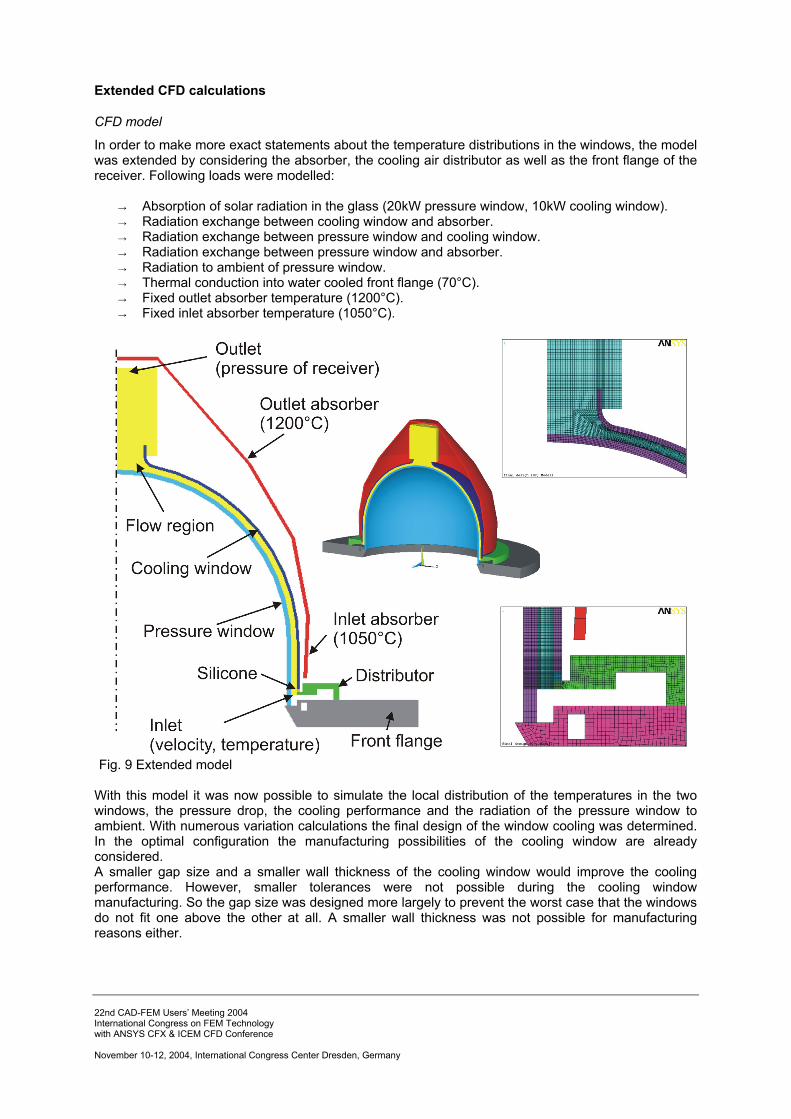
In order to make more exact statements about the temperature distributions in the windows, the model was extended by considering the absorber, the cooling air distributor as well as the front flange of the receiver. Following loads were modelled:
→ Absorption of solar radiation in the glass (20kW pressure window, 10kW cooling window). → Radiation exchange between cooling window and absorber. → Radiation exchange between pressure window and cooling window. → Radiation exchange between pressure window and absorber. → Radiation to ambient of pressure window. → Thermal conduction into water cooled front flange (70°C). → Fixed outlet absorber temperature (1200°C). → Fixed inlet absorber temperature (1050°C).
Fig. 9 Extended model With this model it was now possible to simulate the local distribution of the temperatures in the two windows, the pressure drop, the cooling performance and the radiation of the pressure window to ambient. With numerous variation calculations the final design of the window cooling was determined. In the optimal configuration the manufacturing possibilities of the cooling window are already considered. A smaller gap size and a smaller wall thickness of the cooling window would improve the cooling performance. However, smaller tolerances were not possible during the cooling window manufacturing. So the gap size was designed more largely to prevent the worst case that the windows do not fit one above the other at all. A smaller wall thickness was not possible for manufacturing reasons either.

22nd CAD-FEM Users’ Meeting 2004 International Congress on FEM Technology with ANSYS CFX & ICEM CFD Conference November 10-12, 2004, International Congress Center Dresden, Germany
Optimal configuration
In the following list, the results of the optimal configuration are shown:
gap size: 10 mm cooling window thickness: 5 mm swirl velocity: 40 m/s cooling mass flow: 0.2 kg/s pressure drop in the gap: 100 mbar max. temperature of cooling window: 950 °C max. temperature of pressure window: 835 °C cooling performance: 98 KW outlet temperature of cooling air (in receiver): 525 °C radiation of pressure window to environment: 2.6 KW
The goal to achieve maximum glass temperatures below 800 °C, could not reached. First of all, the cooling window temperature is about 150 K higher than desired. Principal reason for this is the low heat conductivity of the glass. For manufacturing reasons the wall thickness of the cooling window is 5 mm. A smaller wall thickness (3 mm) would reduce the gradients and thus the maximum temperature in the glass. The maximum temperature of the pressure window is caused by a region of nearly zero flow velocity at the vertex of the window. In addition, this region has a direct line of sight to the absorber. In reality the temperature at this location will be less than calculated because of following reasons: 1. Rotational symmetry is perfect in the model. However, in reality there will be irregularities
(small changes in mass flow rates, turbulence, etc.) and so this area will be better cooled than predicted by the model.
2. The central segment of the absorber will be better cooled by the discharging gap flow, which is cooler than the main receiver flow. Hence, absorber radiation load on this window region is smaller than modelled.
Apart from the maximum temperature, the temperatures in the pressure window are rather low (on average 400 °C). This leads to a drastically reduced radiation of the pressure window to ambient.
Fig. 10 Results of extended CFD analyses

22nd CAD-FEM Users’ Meeting 2004 International Congress on FEM Technology with ANSYS CFX & ICEM CFD Conference November 10-12, 2004, International Congress Center Dresden, Germany
Air distributor
For supporting the cooling window and distributing the cooling air an air distributor was designed. The following list gives an overview over all functions of the air distributor:
The Bearing of the cooling window has to → resist the force from pressure drop, → compensate a relative movement between metal and glass components and
seperate the cooling flow from the receiver flow. Leading the cooling flow to the gap between cooling and pressure window. Support of the pressure window. Creation of swirl.
Numerous variants for bearing the cooling window were examined by FE analyses and experiments. The high and unfavorable loads resulted at nearly all variants to relatively high tensile stresses in the cooling window. Due to the brittle material behavior of quartz glass however only relatively low tensile stresses are permissible. This led to the exclusion of most variants. The only feasible variant was sticking the cooling window with high temperature silicone on a groove of the air distributor. The different thermal expansions are compensated by the flexible behavior of the silicone. Further the silicone works as a sealing and can resist the forces by using a large area. Problematic at this variant is the low heat conductivity of silicone, which makes heat conduction from the silicon sealing to cooled parts more difficult. In order to determine the temperatures in the sealing, it was integrated into the CFD model. At the design point (absorber temperature: 1200 °C) the maximum temperature in the sealing is 150 °C. Without cooling air flow in the gap, the temperature of the silicone would rise up to 400 °C, which is 100 °C higher than the allowed temperature of the material.The limited design space led to a complex geometry for distributing the air and creating the swirl. The layout of the geometry was done with analytic calculations of the flow and designed with CAD. Afterwards the air distributor was manufactured using the CAD data by a computer controlled milling machine.
Fig. 12 Air distributor After mounting the two windows on the front flange a simple test was performed to check the proper function of the cooling system. Therefore air was led through the gap and fixed woollen yarns indicated the direction of the flow velocity vectors. The experiment showed, that the swirl of the flow behaves like predicted in CFD simulations.
Fig. 11 Bearing concept
Fig. 13 Mounting of the components Fig. 14 Flow test, velocity vectors of simulation

22nd CAD-FEM Users’ Meeting 2004 International Congress on FEM Technology with ANSYS CFX & ICEM CFD Conference November 10-12, 2004, International Congress Center Dresden, Germany
CFD analyses with real geometry
After manufacturing the cooling window, the window was measured on a 3D measurement machine and the geometry in the CFD model was adapted to the real geometry. The red line in Fig. 14 shows the real measured contour of the cooling window, the blue one is the designed and the green one is the contour of the pressure window. Further calculations with the real geometry showed that the pressure drop is reduced to 60 mbar. The maximum temperature in the pressure window is nearly the same as in the design geometry. Regarding the cooling window, the maximum temperature is about 10 K higher than in the design geometry.
Fig. 14 Measurement data
Fig. 15 CFD model with real geometry The high temperature module was integrated in the test bed at the Plataforma Solar de Almería (PSA) in south Spain in the beginning of 2004. In June and July 2004 the receiver module was tested in connection with a gas turbine. The first evaluation of the measurements showed that the cooling works well. The swirled cooling flow works like CFD calculations predicted. Even the pressure drop was in good agreement with the simulations. Due to a problem with the bearing of the cooling window, it was not possible to finish the experiment during the last test period.
Fig. 16 Integration in receiver / solar operation