Embed Size (px)
Citation preview
ICEM® Surf™ 4.10.2
Quick Reference
November 2011
© Dassault Systèmes 2011.
All rights reserved.
Legal Notices and Contact
Copyright Information
Copyright 2011 Dassault Systèmes. All Rights Reserved.User and training documentation from ICEM is subject to the copyright laws of the United States and other countries and is provided under a license agreement that restricts copying, disclosure, and use of such documentation. ICEM hereby grants to the licensed user the right to make such limited copies in printed form of this documentation if provided on software media, as may be necessary for internal/personal use only and all such copies shall be made in accordance with the license agreement under which the applicable software is licensed to the licensed user. Any copy made shall include the full ICEM copyright notice and any other proprietary notice provided by ICEM to the licensed user from time to time. This documentation may not be disclosed, transferred, modified, or reduced to any form, including, but not limited to, electronic media, or transmitted or made publicly available by any means whatsoever without the prior written consent of ICEM and no authorization is granted to make copies for such purposes.Information described herein is furnished for general information only, is subject to change without notice, and should not, in any circumstances, be construed as a warranty or commitment by ICEM. ICEM neither assumes nor accepts any responsibility or liability for any errors or inaccuracies howsoever arising that may appear in this document.The software described in this document is provided under a written license agreement, contains valuable trade secrets and commercial and intellectual proprietary information, and is protected by the copyright laws of the United States and other countries. It may not be copied or distributed in any form or medium, disclosed to third parties, or used in any manner not provided for in the software licenses agreement except with written prior approval from ICEM. PLEASE NOTE THAT UNAUTHORIZED USE OF SOFTWARE OR ITS DOCUMENTATION CAN RESULT IN CIVIL DAMAGES AND CRIMINAL PROSECUTION.
Registered Trade Marks of Dassault Systèmes or a SubsidiaryCATIA, ICEM, ICEM Surf, ICEM DDN and ICEM Shape Design are trade marks or registered trade marks of Dassault Systèmes or its subsidiaries in the US and/or other countries.
Third-Party Trade Marks3Dconnexion, the 3Dconnexion logo, and other 3Dconnexion marks are owned by 3Dconnexion and may be registered. Adobe is a registered trade mark of Adobe Systems inc.. AIX is a trade mark or registered trade mark of International Business Machines Corporation in the United States and other countries. AMD, ATI and FIREGL are registered trade marks of Advanced Micro Devices. Barco is a registered trade mark of Barco nv. HP-UX is a registered trade mark of the Hewlett-Packard Company. NX I-DEAS is a trade mark or registered trade mark of UGS Corp.. IRIX is a registered trade mark of Silicon Graphics, Inc. Linux is a registered trade mark of Linus Torvalds. Netscape and the Netscape N and Ship's Wheel logos are registered trade marks of Netscape Communications Corporation in the U.S. and other countries. NVIDIA is a registered trade mark of NVIDIA Corporation. Sun Solaris is a trade mark or registered trade mark of Sun Microsystems. Microsoft, Windows, Windows NT, Windows 2000, Windows 2000 Professional, Windows XP, Windows XP Professional, Visual Basic, and the Visual Basic logo are registered trade marks of Microsoft Corporation in the United States and/or other countries. SuSE and its logo are registered trade marks of Novell inc.. Wacom is a registered trade mark of Wacom Company, Ltd.All other trademarks or product names are property of their respective owners.
Licensed Third-Party Technology Information
Certain ICEM software products contain licensed third-party technology: FLEXnet and FLEXlm are registered trade marks of Flexera Software Inc.. LightWork Libraries are copyrighted by LightWork Design 1990-2004. Pro/ENGINEER, CDRS, 3DPAINT are copyrighted by Parametric Technology Corporation. The CADverter for Catia, Cadds, Unigraphics are copyrighted by Theorem Solutions Ltd.
WinX11 library license informationPortions related to the WinX11 library are Copyright (c) 1994 Software Research Associates, Inc. under the following license:Permission to use, copy, modify, and distribute this software and its documentation for any purpose and without fee is hereby granted, provided that the above copyright notice appear in all copies and that both that copyright notice and this permission notice appear in supporting documentation, and that the name of Software Research Associates not be used in advertising or publicity pertaining to distribution of the software without specific, written prior permission. Software Research Associates makes no representations about the suitability of this software for any purpose. It is provided “as is” without express or implied warranty.
UNITED STATES GOVERNMENT RESTRICTED RIGHTS LEGENDThis document and the software described herein are Commercial Computer Documentation and Software, pursuant to FAR 12.212(a)-(b) (OCT'95) or DFARS 227.7202-1(a) and 227.7202-3(a) (JUN'95), is provided to the US Government under a limited commercial license only. For procurements predating the above clauses, use, duplication, or disclosure by the Government is subject to the restrictions set forth in subparagraph (c)(1)(ii) of the Rights in Technical Data and Computer Software Clause at DFARS 252.227-7013 (OCT'88) or Commercial Computer Software-Restricted Rights at FAR 52.227-19(c)(1)-(2) (JUN'87) or FAR 52.227-14 (ALT III), as applicable. 032603
Registered office:10, Rue Marcel Dassault78140 Vélizy-VillacoublayFRANCE
Tel: + 33 1 61 62 61 62Fax: + 33 1 70 73 43 63
Contact Information
Homepage
http://www.3ds.com/products/catia/portfolio
License Keys
http://www.3ds.com/terms/software-keys/
Support Centers
Europe & rest of the world:
Dassault Customer Support Center World WideDassault Systemes Deutschland GmbH HannoverKüsterstraße 830519 HannoverGermany
Phone:Fax:E-mail:Internet:
+49 (0)511 9848 850+49 (0)511 9848 [email protected]://www.3ds.com/support/
USA & Canada: Asia & Pacific:
Dassault Customer Support Center USA & Canada2455 South RoadPoughkeepsieNew York 12601USA
Customer Local Support Centers Asia PacificCustomer Support Center JapanDassault Systèmes K.K.Pier City Shibaura Bldg 10F3-18-1 Kaigan, Minato-ku108-0022 TokyoJapan
Phone:Fax:E-mail:Internet:
+1 (704) 935 5690 (International) +1 (704) 264 [email protected]://www.3ds.com/support/
Phone:Fax:E-mail:Internet:
+81 (0)3 5442 6051+81 (0)3 5442 [email protected] http://www.3ds.com/support/
You can also contact a local office, for native speaking first level support. Please find the contact details below.
Sales
Germany: Italy:
Dassault Systèmes Deutschland GmbH HannoverKüsterstraße 830519 HannoverGermany
Dassault Systèmes ItaliaVia Rossini 1/A20020 LainateItaly
Phone:Fax:E-mail:
+49 (0)511 9848 6+49 (0)511 9848 [email protected]
Phone:Fax:E-mail:
+39 0 233 43061+39 0 233 [email protected]
France: Spain:
Dassault Systèmes10, Rue Marcel DassaultCS 4050178946 Vélizy Villacoublay, Cedex France
Dassault Systèmes España, S. L.Edificio Esade CreapolisAv. de la Torreblanca, 57,Oficina 2B608172 Sant Cugat del VallèsBarcelona – España
Phone:E-mail:
+33 1 6162 7203 [email protected]
Phone:Fax:E-mail:
+34 93 551 08 01+34 93 551 08 [email protected]

USA & Canada: Asia & Pacific:
Dassault Systèmes Americas300 Galleria Officecentre Dr.Suite 305Southfield, MI 48034USA
Dassault Systèmes K.K.Pier City Shibaura Bldg 10F3-18-1 Kaigan, Minato-ku108-0022 TokyoJapan
Phone:Fax:E-mail:
+1 248 351 0741+1 248 351 [email protected]
Phone:Fax:E-mail:
+81 (0)3 5442 6040+81 (0)3 5442 [email protected]
CONTENTS
5
Contents
1 General handling . . . . . . . . . . . . . . . . . . . . . . . . . . . . . . . . . . . . . . . . . . . . . . . . . . . . . . . . . . . . . . . . . . . . . . . . . . . . . . . . . . . . . . . . . . . . . .6
1.1 STARTING/terminating ICEM Surf . . . . . . . . . . . . . . . . . . . . . . . . . . . . . . . . . . . . . . . . . . . . . . . . . . . . . . . . . . . . . . . . . . . . . . . . . . . . . . . . .6
1.2 The user interface . . . . . . . . . . . . . . . . . . . . . . . . . . . . . . . . . . . . . . . . . . . . . . . . . . . . . . . . . . . . . . . . . . . . . . . . . . . . . . . . . . . . . . . . . . . . . .6
1.2.1 Information in the info line . . . . . . . . . . . . . . . . . . . . . . . . . . . . . . . . . . . . . . . . . . . . . . . . . . . . . . . . . . . . . . . . . . . . . . . . . . . . . . . .6
1.2.2 Scaling factors . . . . . . . . . . . . . . . . . . . . . . . . . . . . . . . . . . . . . . . . . . . . . . . . . . . . . . . . . . . . . . . . . . . . . . . . . . . . . . . . . . . . . . . . .6
1.2.3 Mouse button assignment . . . . . . . . . . . . . . . . . . . . . . . . . . . . . . . . . . . . . . . . . . . . . . . . . . . . . . . . . . . . . . . . . . . . . . . . . . . . . . . .6
1.2.4 Special functions block . . . . . . . . . . . . . . . . . . . . . . . . . . . . . . . . . . . . . . . . . . . . . . . . . . . . . . . . . . . . . . . . . . . . . . . . . . . . . . . . . . .7
1.2.5 Geometry functions block . . . . . . . . . . . . . . . . . . . . . . . . . . . . . . . . . . . . . . . . . . . . . . . . . . . . . . . . . . . . . . . . . . . . . . . . . . . . . . . . .9
1.2.6 Service functions block. . . . . . . . . . . . . . . . . . . . . . . . . . . . . . . . . . . . . . . . . . . . . . . . . . . . . . . . . . . . . . . . . . . . . . . . . . . . . . . . . . .9
1.2.7 Status line. . . . . . . . . . . . . . . . . . . . . . . . . . . . . . . . . . . . . . . . . . . . . . . . . . . . . . . . . . . . . . . . . . . . . . . . . . . . . . . . . . . . . . . . . . . . .9
1.3 Manipulation of the symbols in the graphic area . . . . . . . . . . . . . . . . . . . . . . . . . . . . . . . . . . . . . . . . . . . . . . . . . . . . . . . . . . . . . . . . . . . . . .10
1.4 View manipulation using mouse and keyboard . . . . . . . . . . . . . . . . . . . . . . . . . . . . . . . . . . . . . . . . . . . . . . . . . . . . . . . . . . . . . . . . . . . . . . .12
1.5 Control keys. . . . . . . . . . . . . . . . . . . . . . . . . . . . . . . . . . . . . . . . . . . . . . . . . . . . . . . . . . . . . . . . . . . . . . . . . . . . . . . . . . . . . . . . . . . . . . . . . .13
1.5.1 Default assignment of the function keys. . . . . . . . . . . . . . . . . . . . . . . . . . . . . . . . . . . . . . . . . . . . . . . . . . . . . . . . . . . . . . . . . . . . .13
1.5.2 Control keys for system control . . . . . . . . . . . . . . . . . . . . . . . . . . . . . . . . . . . . . . . . . . . . . . . . . . . . . . . . . . . . . . . . . . . . . . . . . . .13
1.5.3 Control keys for text field modifications . . . . . . . . . . . . . . . . . . . . . . . . . . . . . . . . . . . . . . . . . . . . . . . . . . . . . . . . . . . . . . . . . . . . .14
1.6 Standard functions in the window footer . . . . . . . . . . . . . . . . . . . . . . . . . . . . . . . . . . . . . . . . . . . . . . . . . . . . . . . . . . . . . . . . . . . . . . . . . . . .14
1.7 Shortcuts . . . . . . . . . . . . . . . . . . . . . . . . . . . . . . . . . . . . . . . . . . . . . . . . . . . . . . . . . . . . . . . . . . . . . . . . . . . . . . . . . . . . . . . . . . . . . . . . . . . .15
1.8 Licenses. . . . . . . . . . . . . . . . . . . . . . . . . . . . . . . . . . . . . . . . . . . . . . . . . . . . . . . . . . . . . . . . . . . . . . . . . . . . . . . . . . . . . . . . . . . . . . . . . . . . .18
1.9 Notes . . . . . . . . . . . . . . . . . . . . . . . . . . . . . . . . . . . . . . . . . . . . . . . . . . . . . . . . . . . . . . . . . . . . . . . . . . . . . . . . . . . . . . . . . . . . . . . . . . . . . . .20
2 Unified Modelling . . . . . . . . . . . . . . . . . . . . . . . . . . . . . . . . . . . . . . . . . . . . . . . . . . . . . . . . . . . . . . . . . . . . . . . . . . . . . . . . . . . . . . . . . . . . .21
2.1 Work steps for the geometry modelling . . . . . . . . . . . . . . . . . . . . . . . . . . . . . . . . . . . . . . . . . . . . . . . . . . . . . . . . . . . . . . . . . . . . . . . . . . . . .21
2.2 Making objects available for modelling . . . . . . . . . . . . . . . . . . . . . . . . . . . . . . . . . . . . . . . . . . . . . . . . . . . . . . . . . . . . . . . . . . . . . . . . . . . . .22
2.3 Modifying geometry and reference objects . . . . . . . . . . . . . . . . . . . . . . . . . . . . . . . . . . . . . . . . . . . . . . . . . . . . . . . . . . . . . . . . . . . . . . . . . .25
2.4 Defining the Geometry and the Reference . . . . . . . . . . . . . . . . . . . . . . . . . . . . . . . . . . . . . . . . . . . . . . . . . . . . . . . . . . . . . . . . . . . . . . . . . .28
2.5 Defining the Projection Base . . . . . . . . . . . . . . . . . . . . . . . . . . . . . . . . . . . . . . . . . . . . . . . . . . . . . . . . . . . . . . . . . . . . . . . . . . . . . . . . . . . . .30
2.6 Executing modelling functions . . . . . . . . . . . . . . . . . . . . . . . . . . . . . . . . . . . . . . . . . . . . . . . . . . . . . . . . . . . . . . . . . . . . . . . . . . . . . . . . . . . .32
2.7 Saving variants and sessions . . . . . . . . . . . . . . . . . . . . . . . . . . . . . . . . . . . . . . . . . . . . . . . . . . . . . . . . . . . . . . . . . . . . . . . . . . . . . . . . . . . .35
GENERAL HANDLING1
1 General handling
1.1 STARTING/terminating ICEM Surf
Start ICEM Surf
Via “Start – Programs” or by double click onto the program icon.
Start options
Start options are set after the start command of ICEM Surf in the command line “Target” on the “Shortcut” tab in the menu “Properties”. Themenu Properties is activated by right-click onto the program icon.
Terminate ICEM Surf:
File – Exit or ^Q.
1.2 The user interface
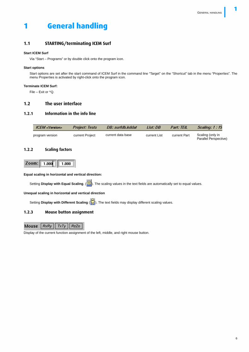
1.2.1 Information in the info line
1.2.2 Scaling factors
Equal scaling in horizontal and vertical direction:
Setting Display with Equal Scaling. ( ). The scaling values in the text fields are automatically set to equal values.
Unequal scaling in horizontal and vertical direction
Setting Display with Different Scaling ( ). The text fields may display different scaling values.
1.2.3 Mouse button assignment
Display of the current function assignment of the left, middle, and right mouse button.
program version current Project current data base current List current Part Scaling (only inParallel Perspective)
6
SPECIAL FUNCTIONS BLOCK1
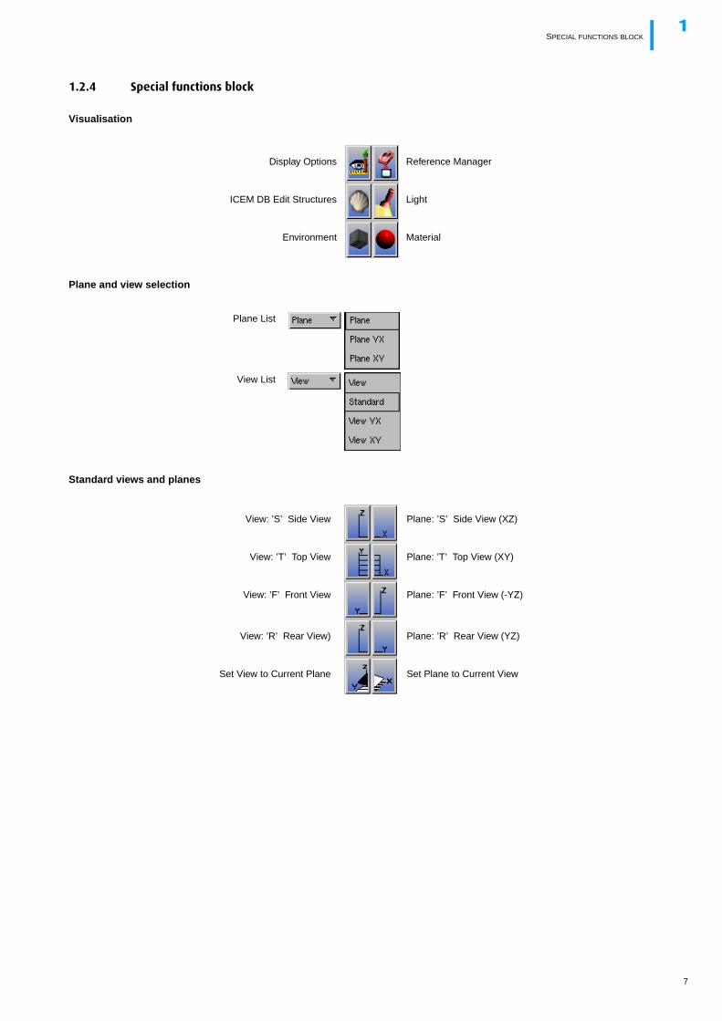
1.2.4 Special functions block
Visualisation
Plane and view selection
Standard views and planes
Display Options
ICEM DB Edit Structures
Environment
Light
Reference Manager
Material
Plane List
View List
Plane: ’S’ Side View (XZ)
Plane: ’T’ Top View (XY)
Plane: ’F’ Front View (-YZ)
Plane: ’R’ Rear View (YZ)
Set Plane to Current View
View: ’S’ Side View
View: ’T’ Top View
View: ’F’ Front View
View: ’R’ Rear View)
Set View to Current Plane
7
SPECIAL FUNCTIONS BLOCK1
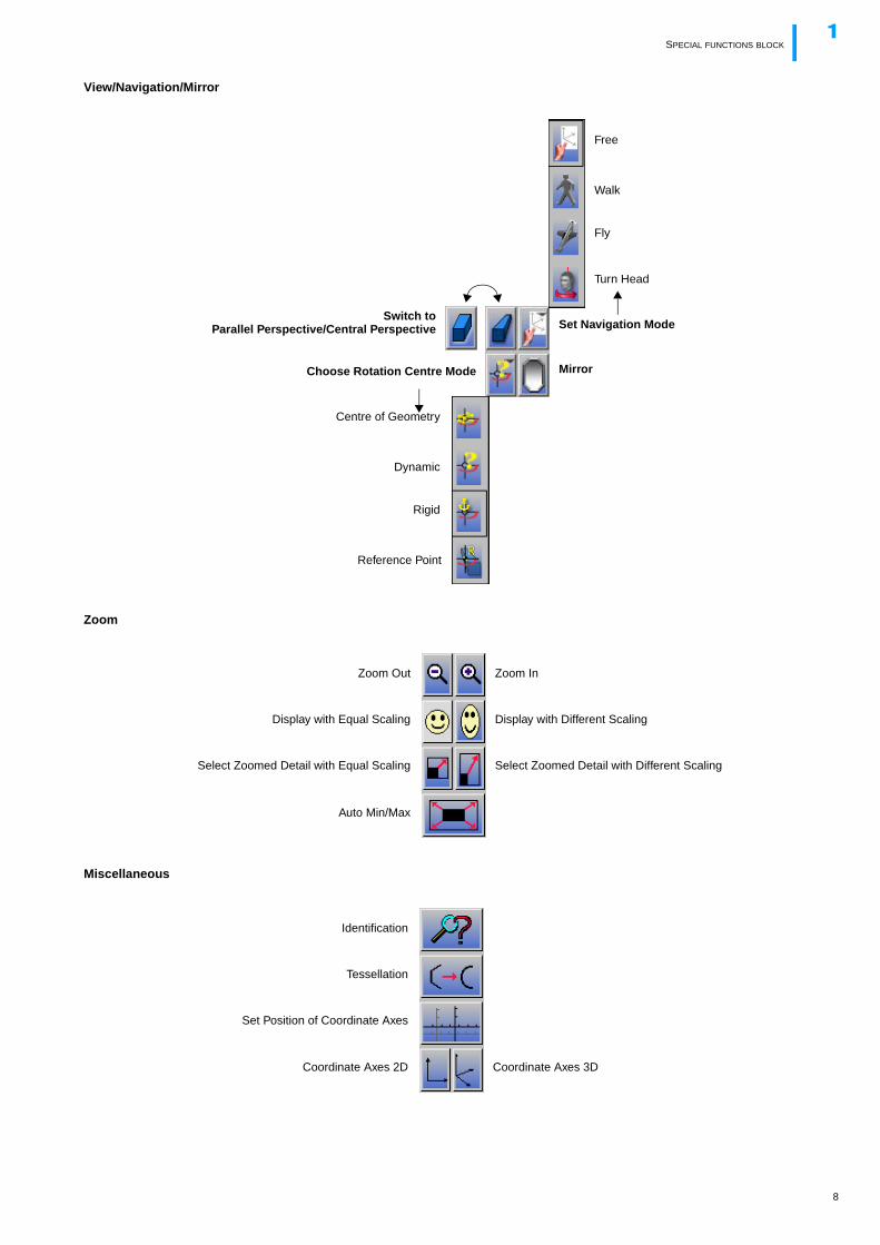
View/Navigation/Mirror
Zoom
Miscellaneous
Mirror
Free
Set Navigation Mode
Walk
Centre of Geometry
Choose Rotation Centre Mode
Dynamic
Switch toParallel Perspective/Central Perspective
Rigid
Reference Point
Fly
Turn Head
Zoom Out
Display with Equal Scaling
Select Zoomed Detail with Equal Scaling
Display with Different Scaling
Zoom In
Select Zoomed Detail with Different Scaling
Auto Min/Max
Identification
Tessellation
Set Position of Coordinate Axes
Coordinate Axes 2D Coordinate Axes 3D
8
GEOMETRY FUNCTIONS BLOCK1
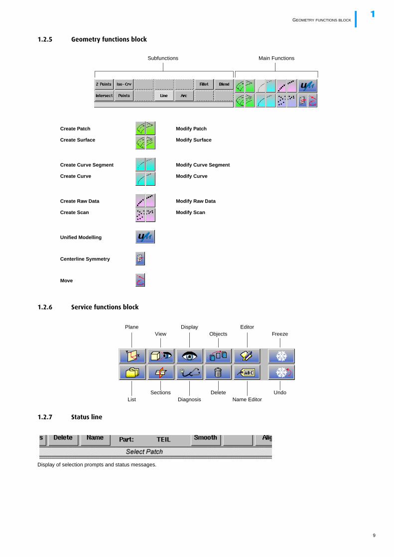
1.2.5 Geometry functions block
1.2.6 Service functions block
1.2.7 Status line
Display of selection prompts and status messages.
Create Patch
Create Surface
Modify Patch
Modify Surface
Create Curve Segment
Create Curve
Modify Curve Segment
Modify Curve
Create Raw Data
Create Scan
Modify Raw Data
Modify Scan
Unified Modelling
Centerline Symmetry
Move
Main FunctionsSubfunctions
Plane DisplayObjects
ListSections
DiagnosisDelete
Editor
Name EditorUndo
FreezeView
9
MANIPULATION OF THE SYMBOLS IN THE GRAPHIC AREA1
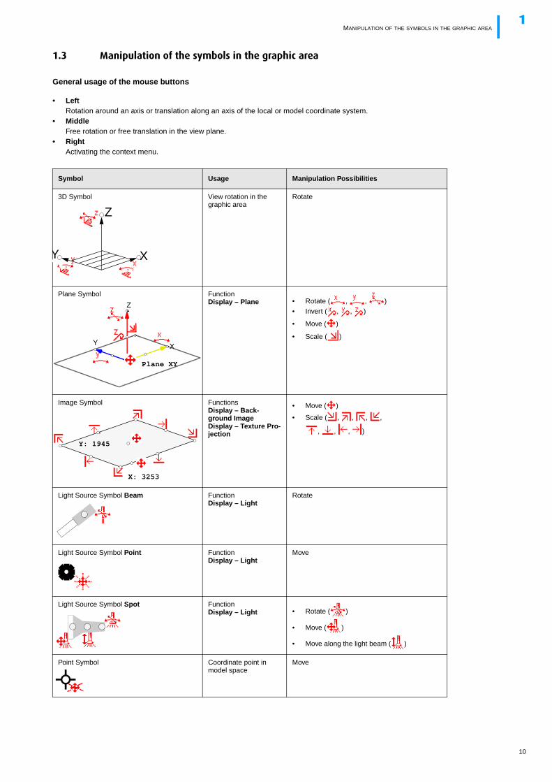
1.3 Manipulation of the symbols in the graphic area
General usage of the mouse buttons
• LeftRotation around an axis or translation along an axis of the local or model coordinate system.
• MiddleFree rotation or free translation in the view plane.
• RightActivating the context menu.
Symbol Usage Manipulation Possibilities
3D Symbol View rotation in the graphic area
Rotate
Plane Symbol FunctionDisplay – Plane • Rotate ( , , )
• Invert ( , , )
• Move ( )
• Scale ( )
Image Symbol FunctionsDisplay – Back-ground ImageDisplay – Texture Pro-jection
• Move ( )
• Scale ( , , , ,
, , , )
Light Source Symbol Beam FunctionDisplay – Light
Rotate
Light Source Symbol Point FunctionDisplay – Light
Move
Light Source Symbol Spot FunctionDisplay – Light • Rotate ( )
• Move ( )
• Move along the light beam ( )
Point Symbol Coordinate point in model space
Move
Y
Z
X
Y
Z
X
Plane XY
Y: 1945
X: 3253
10
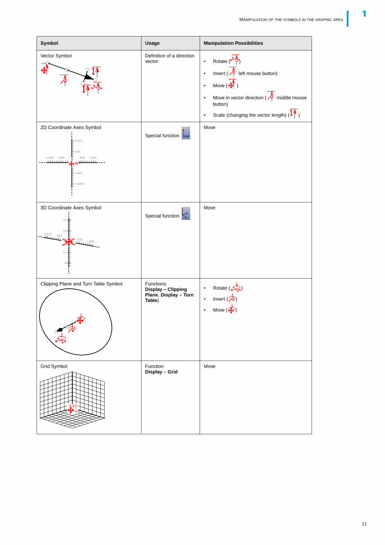
MANIPULATION OF THE SYMBOLS IN THE GRAPHIC AREA1
Vector Symbol Definition of a direction vector • Rotate ( )
• Invert ( left mouse button)
• Move ( )
• Move in vector direction ( middle mouse button)
• Scale (changing the vector length) ( )
2D Coordinate Axes Symbol
Special function
Move
3D Coordinate Axes Symbol
Special function
Move
Clipping Plane and Turn Table Symbol FunctionsDisplay – Clipping Plane, Display – Turn Table)
• Rotate ( )
• Invert ( )
• Move ( )
Grid Symbol FunctionDisplay – Grid
Move
Symbol Usage Manipulation Possibilities
0.0
0.0
500
1000
500 1000
-500
-1000
-500-1000
0.0
0.0 5001000
-500-1000
0.0
500
1000
1500
-500
11
VIEW MANIPULATION USING MOUSE AND KEYBOARD1
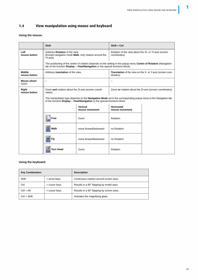
1.4 View manipulation using mouse and keyboard
Using the mouse:
Using the keyboard:
Shift Shift + Ctrl
Leftmouse button
Arbitrary Rotation of the view.(Except navigation mode Walk: only rotation around the Yt-axis)
Rotation of the view about the Xt- or Yt-axis (screen coordinates).
The positioning of the centre of rotation depends on the setting in the popup menu Centre of Rotation (Navigation tab of the function Display – View/Navigation or the special functions block).
Middlemouse button
Arbitrary translation of the view. Translation of the view on the X- or Y-axis (screen coor-dinates).
Mouse wheel: Zoom
– –
Rightmouse button
Zoom and rotation about the Zt-axis (screen coordi-nates).
Zoom or rotation about the Zt-axis (screen coordinates).
The manipulation type depends on the Navigation Mode set in the corresponding popup menu in the Navigation tab of the function Display – View/Navigation or the special functions block.
Verticalmouse movement
Horizontalmouse movement
Free Zoom Rotation
Walk move forward/backward no Rotation
Fly move forward/backward no Rotation
Turn Head Zoom Rotation
Key Combination Description
Shift + arrow keys Continuous rotation around screen axes.
Ctrl + cursor keys Results in a 90° flapping by model axes.
Ctrl + Alt + cursor keys Results in a 90° flapping by screen axes.
Ctrl + Shift Activates the magnifying glass
12
CONTROL KEYS1
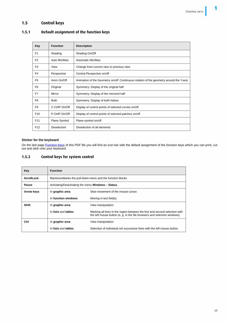
1.5 Control keys
1.5.1 Default assignment of the function keys
Sticker for the keyboard
On the last page Function Keys of this PDF file you will find an icon bar with the default assignment of the function keys which you can print, cutout and stick onto your keyboard.
1.5.2 Control keys for system control
Key Function Description
F1 Shading Shading On/Off
F2 Auto Min/Max Automatic Min/Max
F3 View Change from current view to previous view
F4 Perspective Central Perspective on/off
F5 Anim On/Off Animation of the Geometry on/off: Continuous rotation of the geometry around the Y-axis
F6 Original Symmetry: Display of the original half
F7 Mirror Symmetry: Display of the mirrored half
F8 Both Symmetry: Display of both halves
F9 C-CtrlP On/Off Display of control points of selected curves on/off
F10 P-CtrlP On/Off Display of control points of selected patches on/off
F11 Plane Symbol Plane symbol on/off
F12 Deselection Deselection of all elements
Key Function
ScrollLock Blanks/unblanks the pull-down-menu and the function blocks
Pause Activating/Deactivating the menu Windows – Status.
Arrow keys In graphic area Slow movement of the mouse cursor.
In function windows Moving in text fields).
Shift In graphic area View manipulation
In lists and tables Marking all lines in the region between the first and second selection with the left mouse button (e. g. in the file browsers and selection windows).
Ctrl In graphic area View manipulation
In lists and tables Selection of individual not successive lines with the left mouse button.
13
CONTROL KEYS FOR TEXT FIELD MODIFICATIONS1
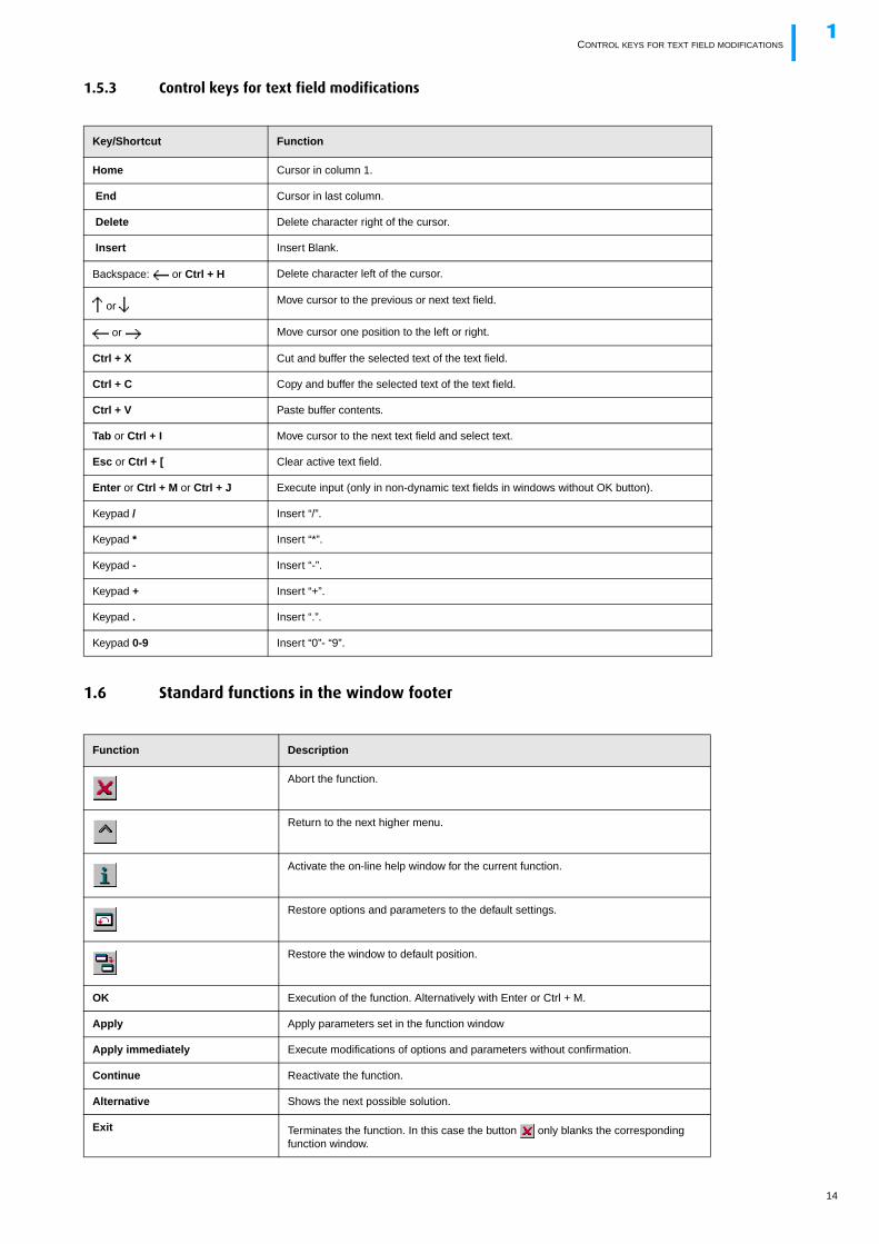
1.5.3 Control keys for text field modifications
1.6 Standard functions in the window footer
Key/Shortcut Function
Home Cursor in column 1.
End Cursor in last column.
Delete Delete character right of the cursor.
Insert Insert Blank.
Backspace: or Ctrl + H Delete character left of the cursor.
or Move cursor to the previous or next text field.
or Move cursor one position to the left or right.
Ctrl + X Cut and buffer the selected text of the text field.
Ctrl + C Copy and buffer the selected text of the text field.
Ctrl + V Paste buffer contents.
Tab or Ctrl + I Move cursor to the next text field and select text.
Esc or Ctrl + [ Clear active text field.
Enter or Ctrl + M or Ctrl + J Execute input (only in non-dynamic text fields in windows without OK button).
Keypad / Insert “/”.
Keypad * Insert “*”.
Keypad - Insert “-”.
Keypad + Insert “+”.
Keypad . Insert “.”.
Keypad 0-9 Insert “0”- “9”.
Function Description
Abort the function.
Return to the next higher menu.
Activate the on-line help window for the current function.
Restore options and parameters to the default settings.
Restore the window to default position.
OK Execution of the function. Alternatively with Enter or Ctrl + M.
Apply Apply parameters set in the function window
Apply immediately Execute modifications of options and parameters without confirmation.
Continue Reactivate the function.
Alternative Shows the next possible solution.
Exit Terminates the function. In this case the button only blanks the corresponding function window.
14
SHORTCUTS1
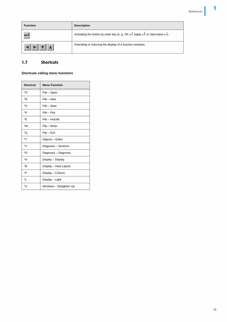
1.7 Shortcuts
Shortcuts calling menu functions
Activating the button by enter key (e. g. OK , Apply , or Alternative ).
Extending or reducing the display of a function windows.
Shortcut Menu Function
^O File – Open
^N File – New
^S File – Save
^P File – Plot
^E File – Include
^W File – Write
^Q File – Exit
^T Objects – Editor
^Y Diagnosis – Sections
^D Diagnosis – Diagnosis
^A Display – Display
^B Display – View Layout
^F Display – Colours
^L Display – Light
^U Windows – Straighten Up
Function Description
15
SHORTCUTS1
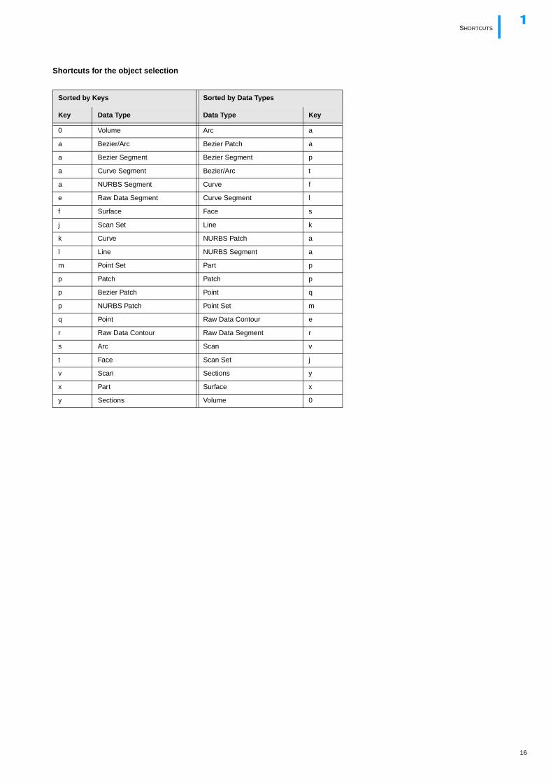
Shortcuts for the object selection
Sorted by Keys Sorted by Data Types
Key Data Type Data Type Key
0 Volume Arc a
a Bezier/Arc Bezier Patch a
a Bezier Segment Bezier Segment p
a Curve Segment Bezier/Arc t
a NURBS Segment Curve f
e Raw Data Segment Curve Segment l
f Surface Face s
j Scan Set Line k
k Curve NURBS Patch a
l Line NURBS Segment a
m Point Set Part p
p Patch Patch p
p Bezier Patch Point q
p NURBS Patch Point Set m
q Point Raw Data Contour e
r Raw Data Contour Raw Data Segment r
s Arc Scan v
t Face Scan Set j
v Scan Sections y
x Part Surface x
y Sections Volume 0
16
SHORTCUTS1
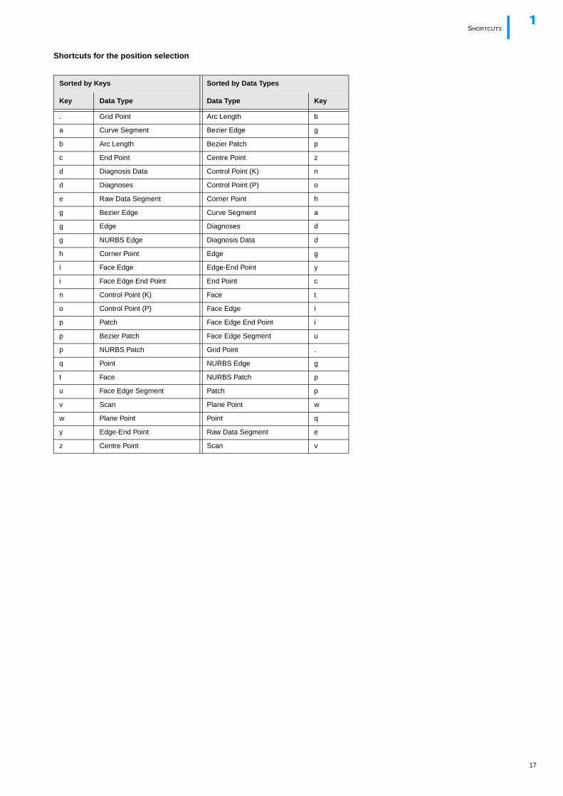
Shortcuts for the position selection
Sorted by Keys Sorted by Data Types
Key Data Type Data Type Key
. Grid Point Arc Length b
a Curve Segment Bezier Edge g
b Arc Length Bezier Patch p
c End Point Centre Point z
d Diagnosis Data Control Point (K) n
d Diagnoses Control Point (P) o
e Raw Data Segment Corner Point h
g Bezier Edge Curve Segment a
g Edge Diagnoses d
g NURBS Edge Diagnosis Data d
h Corner Point Edge g
i Face Edge Edge-End Point y
i Face Edge End Point End Point c
n Control Point (K) Face t
o Control Point (P) Face Edge i
p Patch Face Edge End Point i
p Bezier Patch Face Edge Segment u
p NURBS Patch Grid Point .
q Point NURBS Edge g
t Face NURBS Patch p
u Face Edge Segment Patch p
v Scan Plane Point w
w Plane Point Point q
y Edge-End Point Raw Data Segment e
z Centre Point Scan v
17
LICENSES1
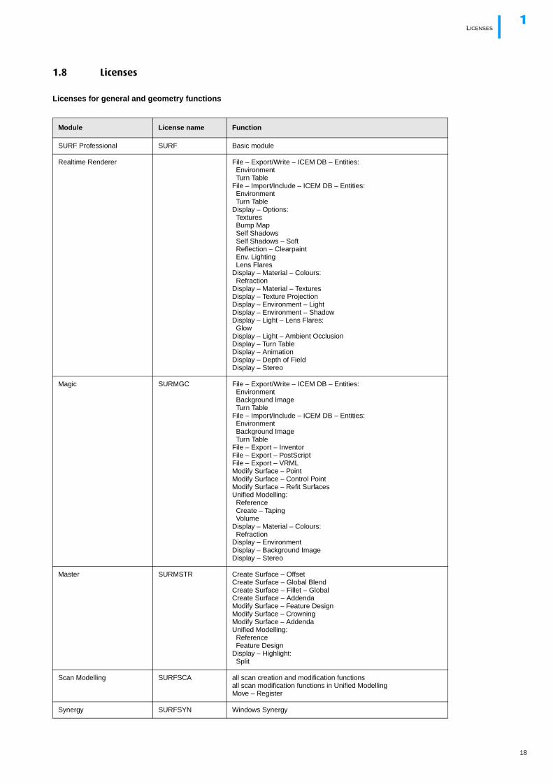
1.8 Licenses
Licenses for general and geometry functions
Module License name Function
SURF Professional SURF Basic module
Realtime Renderer File – Export/Write – ICEM DB – Entities:EnvironmentTurn Table
File – Import/Include – ICEM DB – Entities:EnvironmentTurn Table
Display – Options:TexturesBump MapSelf ShadowsSelf Shadows – SoftReflection – ClearpaintEnv. LightingLens Flares
Display – Material – Colours:Refraction
Display – Material – TexturesDisplay – Texture ProjectionDisplay – Environment – LightDisplay – Environment – ShadowDisplay – Light – Lens Flares:Glow
Display – Light – Ambient OcclusionDisplay – Turn TableDisplay – AnimationDisplay – Depth of FieldDisplay – Stereo
Magic SURMGC File – Export/Write – ICEM DB – Entities:EnvironmentBackground ImageTurn Table
File – Import/Include – ICEM DB – Entities:EnvironmentBackground ImageTurn Table
File – Export – InventorFile – Export – PostScriptFile – Export – VRMLModify Surface – PointModify Surface – Control PointModify Surface – Refit SurfacesUnified Modelling:ReferenceCreate – TapingVolume
Display – Material – Colours:Refraction
Display – EnvironmentDisplay – Background ImageDisplay – Stereo
Master SURMSTR Create Surface – OffsetCreate Surface – Global BlendCreate Surface – Fillet – GlobalCreate Surface – AddendaModify Surface – Feature DesignModify Surface – CrowningModify Surface – AddendaUnified Modelling:ReferenceFeature Design
Display – Highlight:Split
Scan Modelling SURFSCA all scan creation and modification functionsall scan modification functions in Unified ModellingMove – Register
Synergy SURFSYN Windows Synergy
18
LICENSES1
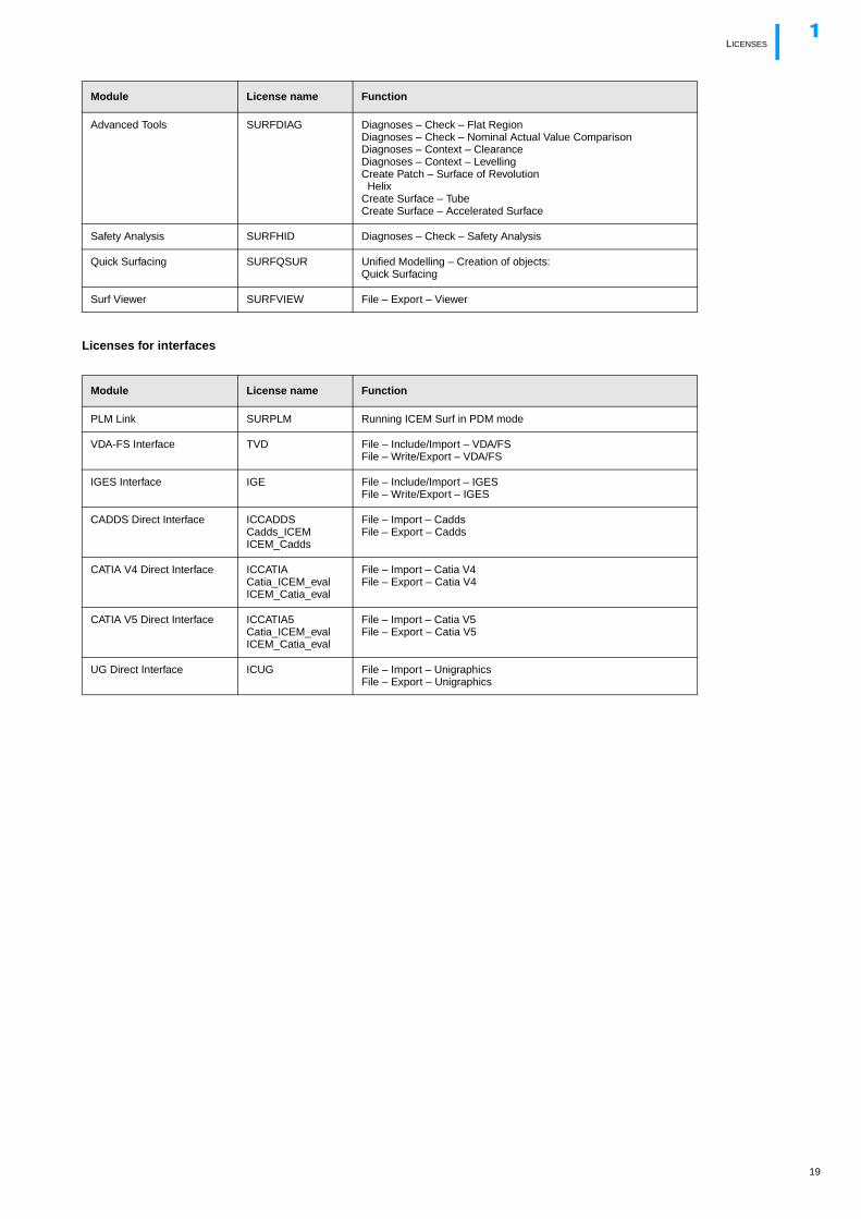
Licenses for interfaces
Advanced Tools SURFDIAG Diagnoses – Check – Flat RegionDiagnoses – Check – Nominal Actual Value ComparisonDiagnoses – Context – ClearanceDiagnoses – Context – LevellingCreate Patch – Surface of RevolutionHelix
Create Surface – TubeCreate Surface – Accelerated Surface
Safety Analysis SURFHID Diagnoses – Check – Safety Analysis
Quick Surfacing SURFQSUR Unified Modelling – Creation of objects:Quick Surfacing
Surf Viewer SURFVIEW File – Export – Viewer
Module License name Function
PLM Link SURPLM Running ICEM Surf in PDM mode
VDA-FS Interface TVD File – Include/Import – VDA/FSFile – Write/Export – VDA/FS
IGES Interface IGE File – Include/Import – IGESFile – Write/Export – IGES
CADDS Direct Interface ICCADDSCadds_ICEMICEM_Cadds
File – Import – CaddsFile – Export – Cadds
CATIA V4 Direct Interface ICCATIACatia_ICEM_evalICEM_Catia_eval
File – Import – Catia V4File – Export – Catia V4
CATIA V5 Direct Interface ICCATIA5Catia_ICEM_evalICEM_Catia_eval
File – Import – Catia V5File – Export – Catia V5
UG Direct Interface ICUG File – Import – UnigraphicsFile – Export – Unigraphics
Module License name Function
19
NOTES1
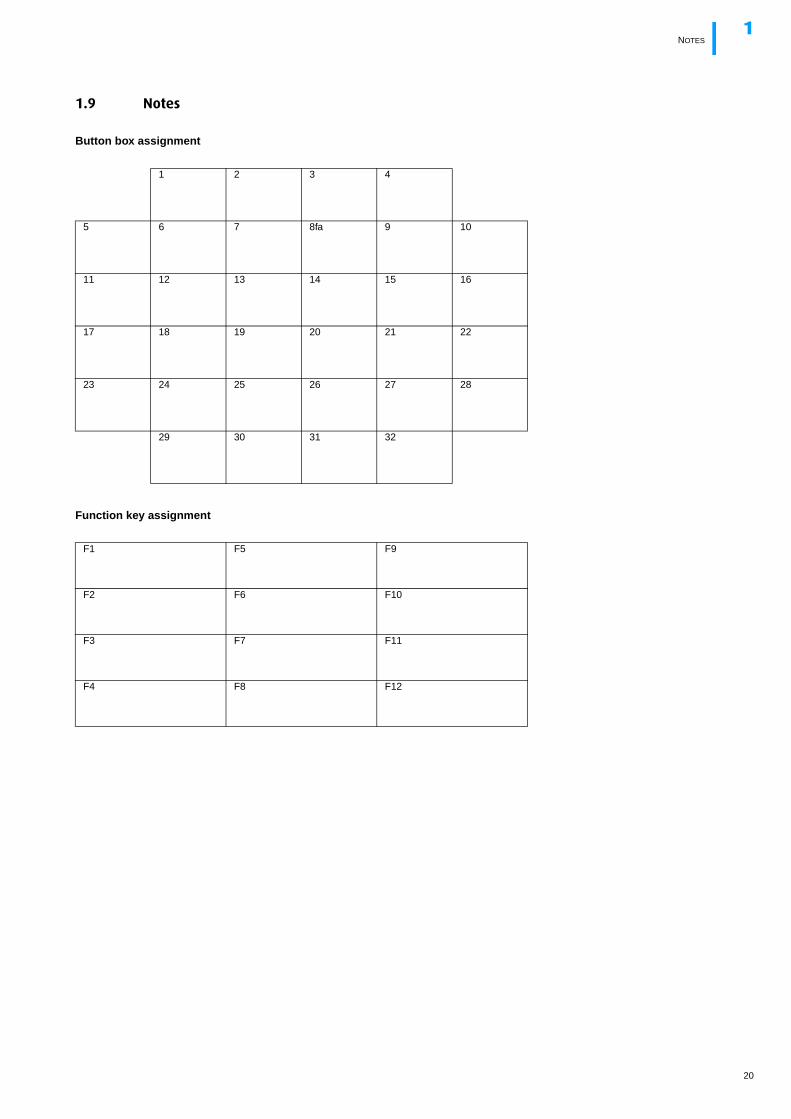
1.9 Notes
Button box assignment
Function key assignment
1 2 3 4
5 6 7 8fa 9 10
11 12 13 14 15 16
17 18 19 20 21 22
23 24 25 26 27 28
29 30 31 32
F1 F5 F9
F2 F6 F10
F3 F7 F11
F4 F8 F12
20
UNIFIED MODELLING2
2 Unified Modelling
2.1 Work steps for the geometry modelling
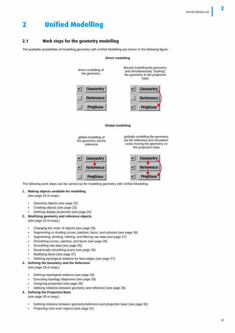
The available possibilities of modelling geometry with Unified Modelling are shown in the following figure:
The following work steps can be carried out for modelling geometry with Unified Modelling:
1. Making objects available for modelling(see page 22 et seqq.)
• Selecting objects (see page 22)• Creating objects (see page 23)• Defining display properties (see page 24)
2. Modifying geometry and reference objects(see page 25 et seqq.)
• Changing the order of objects (see page 25)• Segmenting or dividing curves, patches, faces, and volumes (see page 26)• Segmenting, dividing, refining, and filtering raw data (see page 27)• Smoothing curves, patches, and faces (see page 26)• Smoothing raw data (see page 26)• Dynamically smoothing scans (see page 26)• Modifying faces (see page 27)• Defining topological relations for face edges (see page 27)
3. Defining the Geometry and the Reference(see page 28 et seqq.)
• Defining topological relations (see page 28)• Executing topology diagnoses (see page 29)• Assigning properties (see page 29)• Defining relations between geometry and reference (see page 29)
4. Defining the Projection Base(see page 30 et seqq.)
• Defining relations between geometry/reference and projection base (see page 30)• Projecting onto scan regions (see page 31)
direct modelling of the geometry
global modelling of the geometry via the
reference
directly modelling the geometry and simultaneously “sucking” the geometry to the projection
base
globally modelling the geometry via the reference and simultane-ously moving the geometry on
the projection base
Direct modelling
Global modelling
21
MAKING OBJECTS AVAILABLE FOR MODELLING2
• Projecting onto feature lines (see page 31)• Executing diagnoses for the projection onto surfaces (see page 32)
5. Executing modelling functions(see page 32 et seqq.)
• Point/Control Point Modification (see page 33)• Feature Design (see page 34)• Crowning (see page 34)• Dynamic Move (see page 34)• Volume modelling (see page 35)
6. Saving variants and sessions(see page 35 et seqq.)
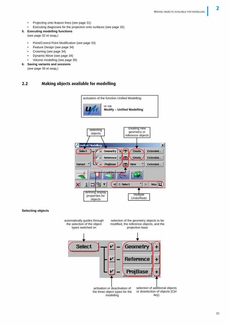
2.2 Making objects available for modelling
Selecting objects
selecting objects
defining display properties for
objects
creating new geometry or
reference objects
or viaModify – Unified Modelling
activation of the function Unified Modelling:
multiple Undo/Redo
selection of the geometry objects to be modified, the reference objects, and the
projection base
selection of additional objects or deselection of objects (Ctrl
key)
activation or deactivation of the three object types for the
modelling
automatically guides through the selection of the object
types switched on
22
MAKING OBJECTS AVAILABLE FOR MODELLING2
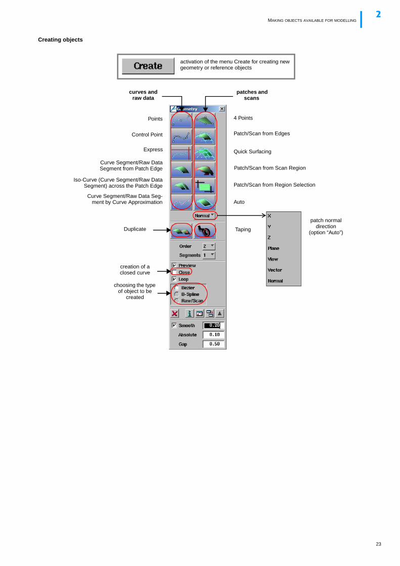
Creating objects
curves and raw data
patches and scans
Duplicate
activation of the menu Create for creating new geometry or reference objects
choosing the type of object to be
created
Points
Control Point
Iso-Curve (Curve Segment/Raw DataSegment) across the Patch Edge
Curve Segment/Raw Data Seg-ment by Curve Approximation
Curve Segment/Raw DataSegment from Patch Edge
4 Points
Patch/Scan from Edges
Quick Surfacing
Auto
patch normal direction
(option “Auto”)
creation of a closed curve
Patch/Scan from Region Selection
Express
Patch/Scan from Scan Region
Taping
23
MAKING OBJECTS AVAILABLE FOR MODELLING2
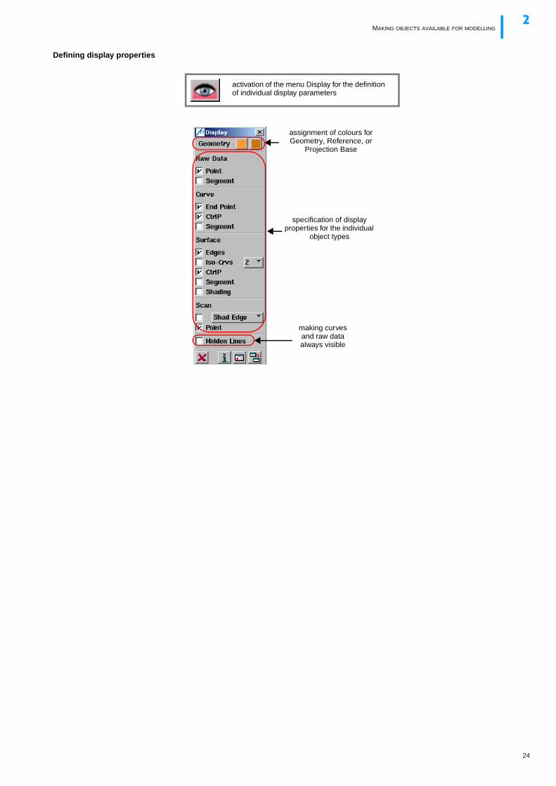
Defining display properties
assignment of colours for Geometry, Reference, or
Projection Base
specification of display properties for the individual
object types
activation of the menu Display for the definition of individual display parameters
making curves and raw data always visible
24
MODIFYING GEOMETRY AND REFERENCE OBJECTS2
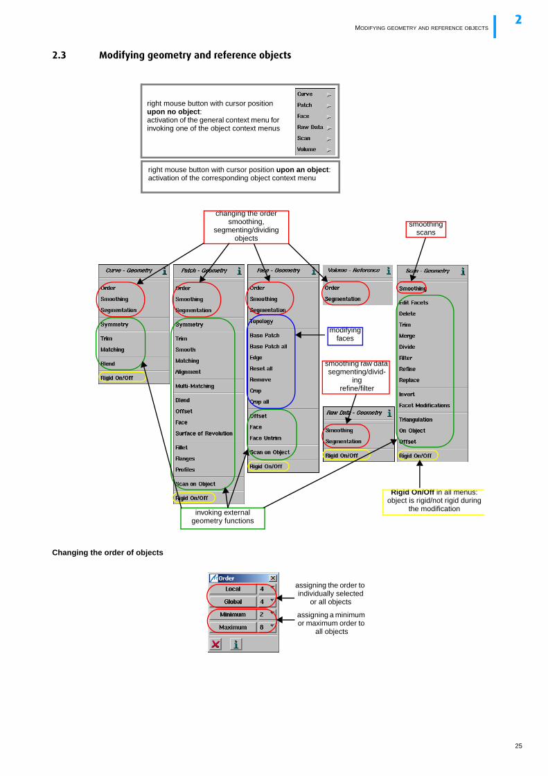
2.3 Modifying geometry and reference objects
Changing the order of objects
changing the ordersmoothing,
segmenting/dividing objects
modifying faces
right mouse button with cursor position upon no object:activation of the general context menu for invoking one of the object context menus
right mouse button with cursor position upon an object: activation of the corresponding object context menu
smoothing raw data segmenting/divid-
ingrefine/filter
smoothing scans
Rigid On/Off in all menus:object is rigid/not rigid during
the modificationinvoking external geometry functions
assigning the order to individually selected
or all objects
assigning a minimum or maximum order to
all objects
25
MODIFYING GEOMETRY AND REFERENCE OBJECTS2
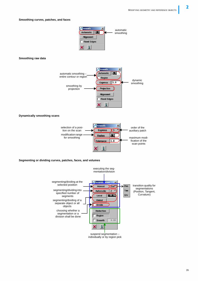
Smoothing curves, patches, and faces
Smoothing raw data
Dynamically smoothing scans
Segmenting or dividing curves, patches, faces, and volumes
automatic smoothing
automatic smoothing – entire contour or region
dynamic smoothing
smoothing by projection
selection of a posi-tion on the scan
order of the auxiliary patch
modification range for smoothing maximum modi-
fication of the scan points
choosing whether a segmentation or a
division shall be done
segmenting/dividing at the selected position
segmenting/dividing into specified number of
segments
transition quality for segmentations
(Position, Tangent, Curvature)
executing the seg-mentation/division
suspend segmentation – individually or by region pick
segmenting/dividing of a separate object or all
objects
26
MODIFYING GEOMETRY AND REFERENCE OBJECTS2
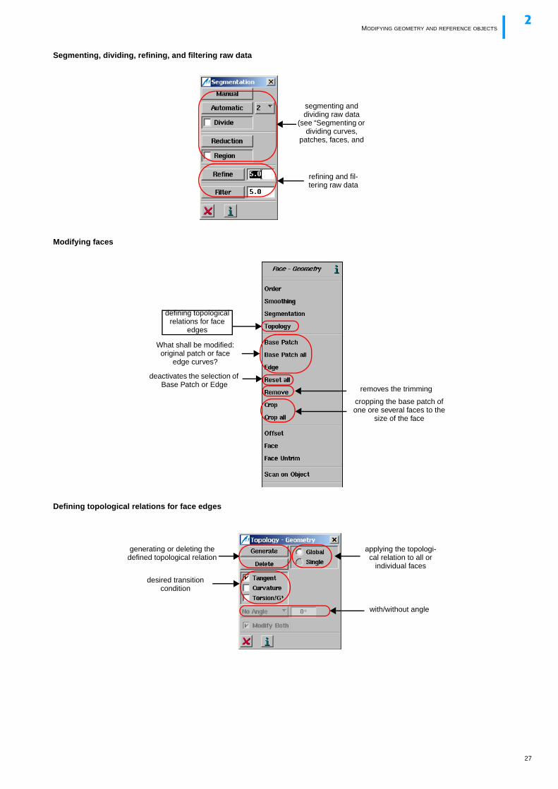
Segmenting, dividing, refining, and filtering raw data
Modifying faces
Defining topological relations for face edges
segmenting and dividing raw data
(see “Segmenting or dividing curves,
patches, faces, and
refining and fil-tering raw data
What shall be modified: original patch or face
edge curves?
deactivates the selection of Base Patch or Edge
removes the trimming
cropping the base patch of one ore several faces to the
size of the face
defining topological relations for face
edges
generating or deleting the defined topological relation
applying the topologi-cal relation to all or
individual faces
desired transition condition
with/without angle
27
DEFINING THE GEOMETRY AND THE REFERENCE2
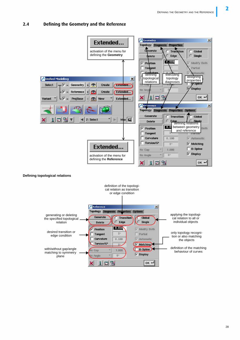
2.4 Defining the Geometry and the Reference
Defining topological relations
assigning properties
defining relations between geometry
and reference
executing topology
diagnoses
activation of the menu for defining the Geometry
activation of the menu for defining the Reference
defining topological relations
generating or deleting the specified topological
relation
definition of the topologi-cal relation as transition
or edge condition
applying the topologi-cal relation to all or individual objects
desired transition or edge condition
with/without gap/angle matching to symmetry
plane
only topology recogni-tion or also matching
the objects
definition of the matching behaviour of curves
28
DEFINING THE GEOMETRY AND THE REFERENCE2
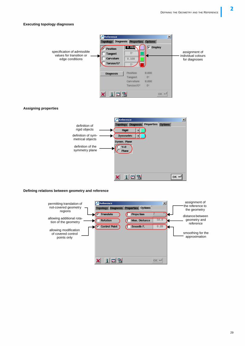
Executing topology diagnoses
Assigning properties
Defining relations between geometry and reference
specification of admissible values for transition or
edge conditions
assignment of individual colours
for diagnoses
definition of the symmetry plane
definition of rigid objects
definition of sym-metrical objects
permitting translation of not-covered geometry
regions
allowing additional rota-tion of the geometry
allowing modification of covered control
points only
assignment of the reference to the geometry
distance between geometry and
reference
smoothing for the approximation
29
DEFINING THE PROJECTION BASE2
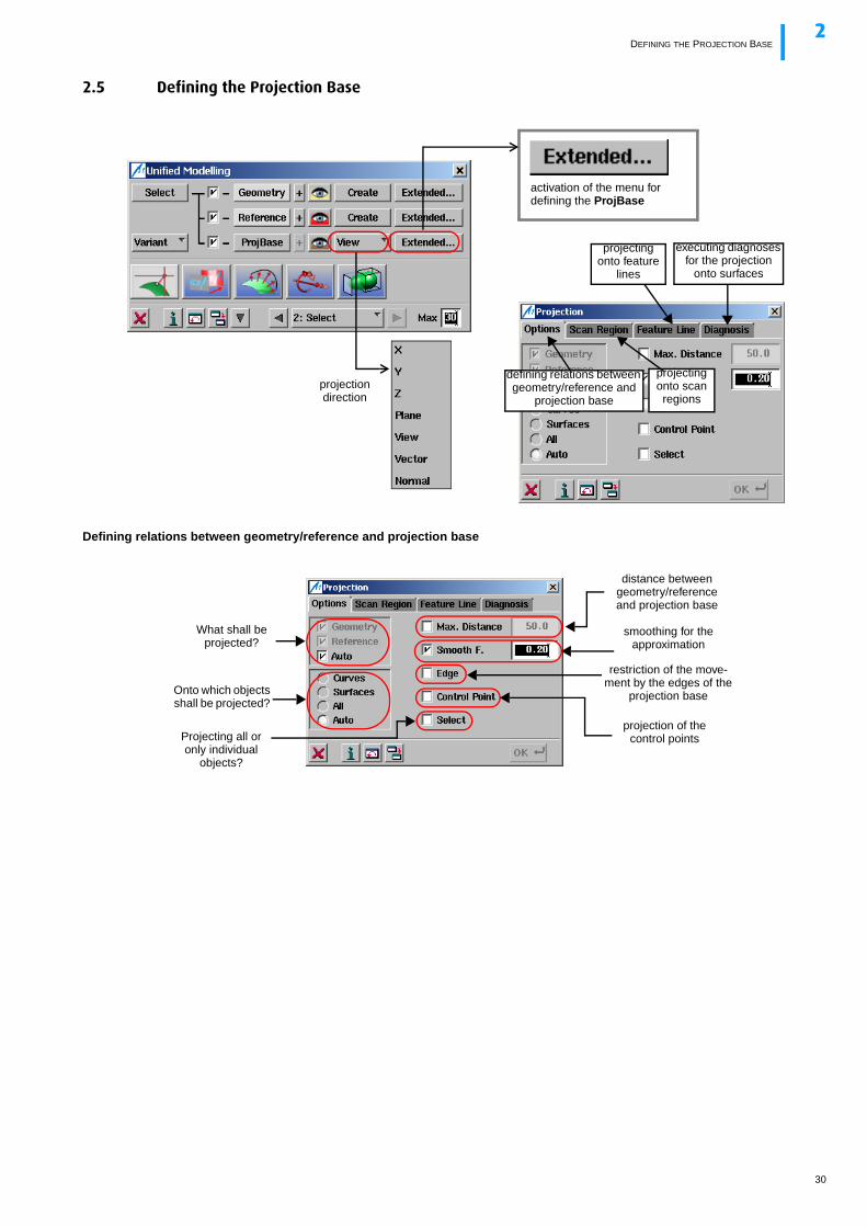
2.5 Defining the Projection Base
Defining relations between geometry/reference and projection base
projection direction
projecting onto feature
lines
defining relations between geometry/reference and
projection base
projecting onto scan regions
executing diagnoses for the projection
onto surfaces
activation of the menu for defining the ProjBase
What shall be projected?
Onto which objects shall be projected?
distance between geometry/reference and projection base
smoothing for the approximation
restriction of the move-ment by the edges of the
projection base
projection of the control pointsProjecting all or
only individual objects?
30
DEFINING THE PROJECTION BASE2
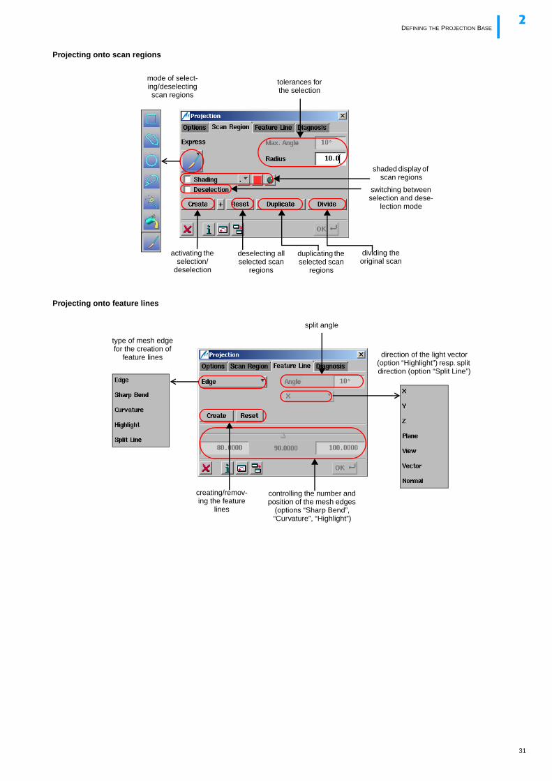
Projecting onto scan regions
Projecting onto feature lines
mode of select-ing/deselecting scan regions
tolerances for the selection
shaded display of scan regions
switching between selection and dese-
lection mode
duplicating the selected scan
regions
dividing the original scan
deselecting all selected scan
regions
activating the selection/
deselection
direction of the light vector (option “Highlight”) resp. split direction (option “Split Line”)
type of mesh edge for the creation of
feature lines
split angle
creating/remov-ing the feature
lines
controlling the number and position of the mesh edges
(options “Sharp Bend”, “Curvature”, “Highlight”)
31
EXECUTING MODELLING FUNCTIONS2
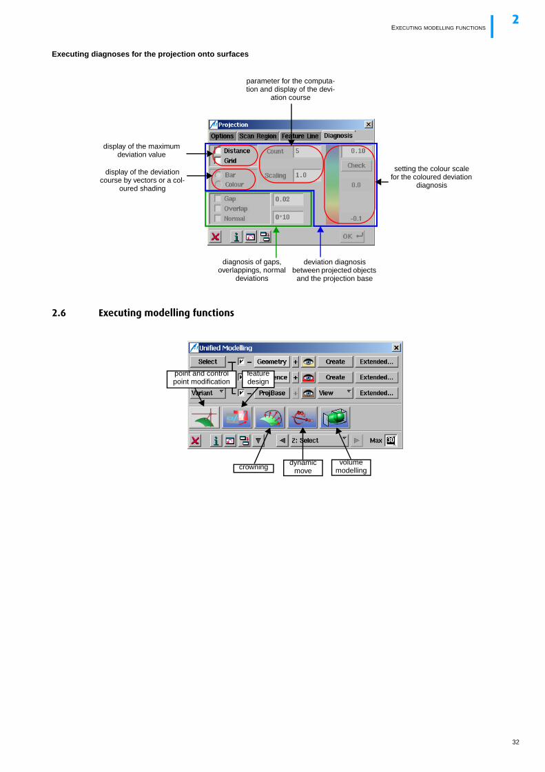
Executing diagnoses for the projection onto surfaces
2.6 Executing modelling functions
diagnosis of gaps, overlappings, normal
deviations
display of the deviation course by vectors or a col-
oured shading
display of the maximum deviation value
parameter for the computa-tion and display of the devi-
ation course
setting the colour scale for the coloured deviation
diagnosis
deviation diagnosis between projected objects
and the projection base
point and control point modification
dynamic move
feature design
crowningvolume
modelling
32
EXECUTING MODELLING FUNCTIONS2
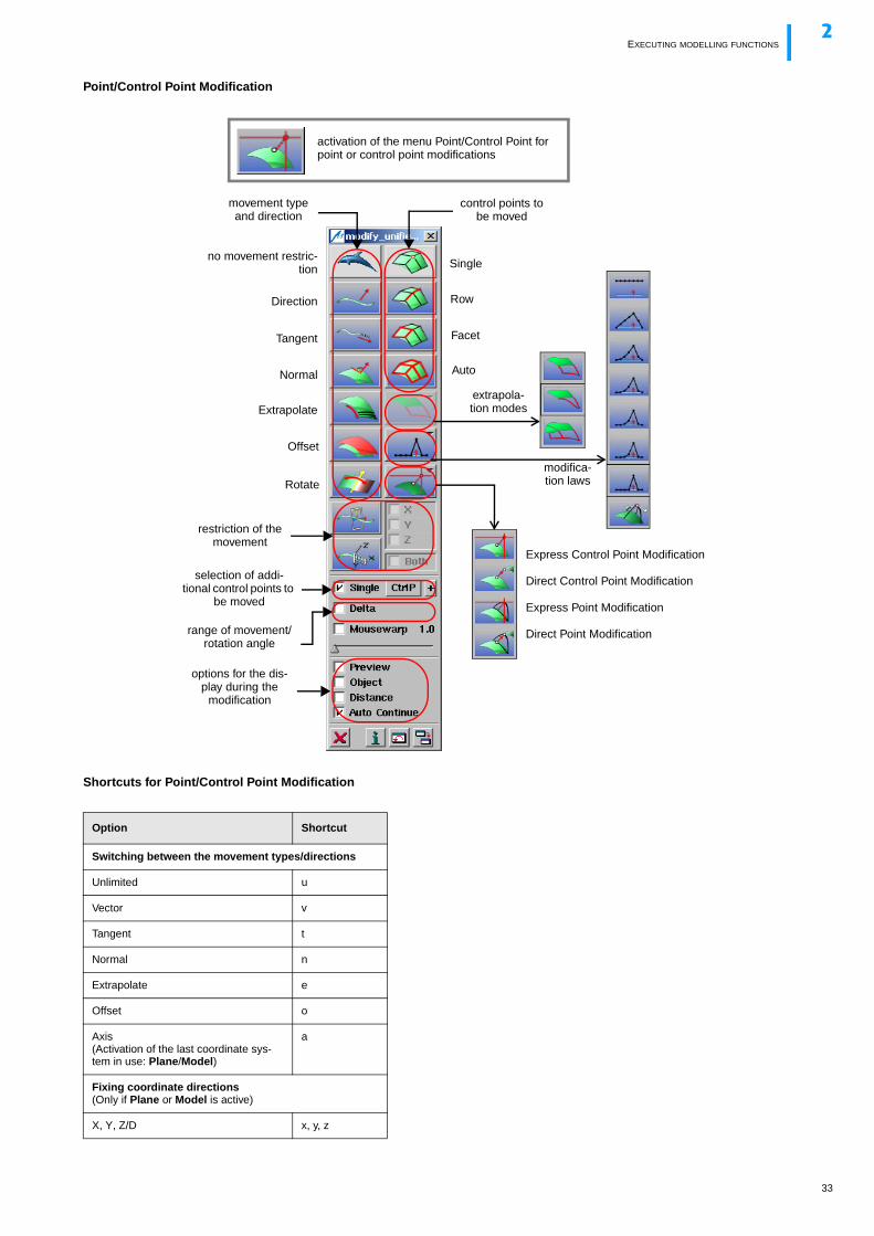
Point/Control Point Modification
Shortcuts for Point/Control Point Modification
Option Shortcut
Switching between the movement types/directions
Unlimited u
Vector v
Tangent t
Normal n
Extrapolate e
Offset o
Axis(Activation of the last coordinate sys-tem in use: Plane/Model)
a
Fixing coordinate directions(Only if Plane or Model is active)
X, Y, Z/D x, y, z
movement type and direction
restriction of the movement
selection of addi-tional control points to
be moved
range of movement/rotation angle
no movement restric-tion
Direction
Tangent
Normal
Extrapolate
Offset
Rotate
control points to be moved
activation of the menu Point/Control Point for point or control point modifications
Single
Row
Facet
Auto
options for the dis-play during the
modification
modifica-tion laws
Express Control Point Modification
Direct Control Point Modification
Express Point Modification
Direct Point Modification
extrapola-tion modes
33
EXECUTING MODELLING FUNCTIONS2
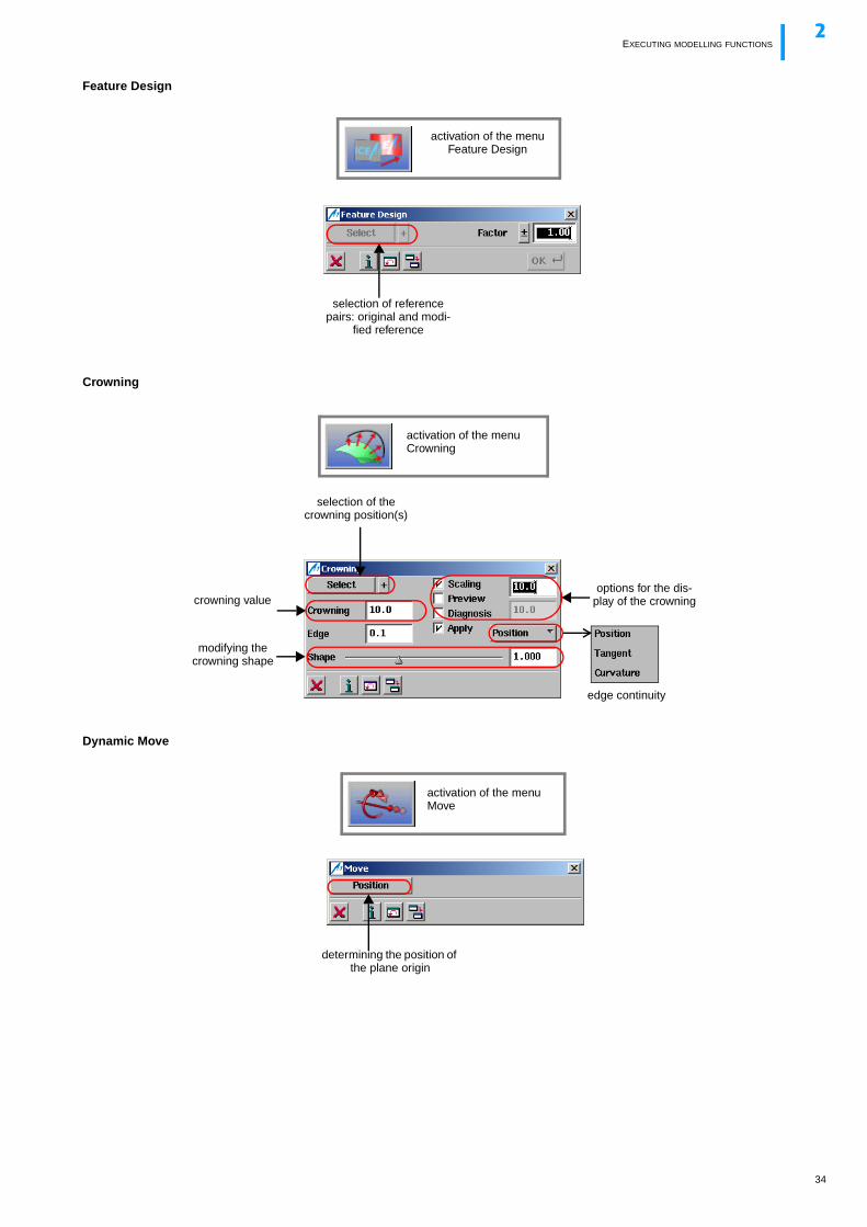
Feature Design
Crowning
Dynamic Move
selection of reference pairs: original and modi-
fied reference
activation of the menu Feature Design
crowning value
selection of the crowning position(s)
edge continuity
options for the dis-play of the crowning
modifying the crowning shape
activation of the menu Crowning
activation of the menu Move
determining the position of the plane origin
34
SAVING VARIANTS AND SESSIONS2
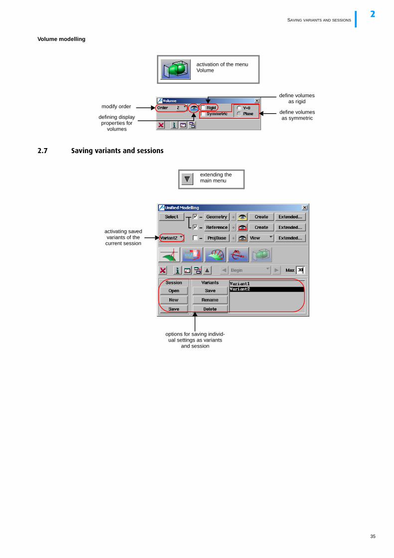
Volume modelling
2.7 Saving variants and sessions
activation of the menu Volume
defining display properties for
volumes
modify order
define volumes as rigid
define volumes as symmetric
extending the main menu
options for saving individ-ual settings as variants
and session
activating saved variants of the current session
35
INDEX
36
Index
AAlternative 14Animation 13Apply 14Apply immediately 14Arrow keys 13Auto Min/Max 8Automatic Min/Max 13
BBackspace 14Buffer 14
CCenterline Symmetry 9Central Perspective 8, 13Centre of Rotation
Centre of Geometry 8Dynamic 8Reference Point 8Rigid 8
Context MenuUnified Modeling 25
Continue 14Control Keys 13
Backspace 14Ctrl + Cursor Keys 12Cursor Keys 12, 14Esc 14Function Keys 13System Control 13Tab 14Text Field 14Text Field Modification 14
Control Point ModificationUnified Modeling 33
Coordinate Axes 8Copy 14Crowning
Unified Modeling 34Ctrl + Cursor Keys 12Ctrl Key 13Cursor Keys 12, 14
DDelete
Service Functions Block 9Deselection 13Diagnosis
Service Functions Block 9Display
Mirrored 13Original 13Original + Mirrored 13selected Control Points 13Service Functions Block 9Unified Modeling 24
Display Options 7Display with Different Scaling 8Display with Equal Scaling 8Divide
Unified Modeling 26
EEnvironment 7Esc 14Exit
a function 14ICEM Surf 6
FFeature Design
Unified Modeling 34Freeze
Service Functions Block 9Function Keys 13
GGeometry Functions 9
IICEM DB Edit Structures 7Identification 8Info Line 6
LLicenses 18Light 7Lists
Service Functions Block 9
MMagnifying Glass 12Material 7Mirror 8Mouse Button Assignment 6, 12Move 9
Unified Modeling 34
NName Editor
Service Functions Block 9Navigation Mode
Fly 8Free 8Turn Head 8Walk 8
OObjects
Service Functions Block 9On-line Help (Activation) 14
PParallel Perspective 8Paste 14Pause 13Plane List 7Plane Symbol 13Point Modification
Unified Modeling 33Previous View 13
RReference Manager 7Restore Variables 14Restore Window Position 14
SScaling Factors 6ScrollLock 13Sections
Service Functions Block 9Select Zoomed Detail with Different Scaling 8Select Zoomed Detail with Equal Scaling 8Selection (Shortcuts) 16Service Functions 9Set Position of Coordinate Axes 8Shading 13Shift-Taste 13Shortcuts
Menu Functions 15Selection 16Unified Modeling 33
Special functions 7Standard Perspective 7Standard planes 7Standard views 7Start ICEM Surf 6Start Options 6Status Line 9
Status Window 13System Control 13
TTab 14Tessellation 8Text Field Modification 14Topology
Unified Modeling 28
UUndo
Service Functions Block 9Unified Modeling
Context Menus 25Control Point Modification 33Creation 23Crowning 34Diagnoses for Projection 32Diagnoses for Topology 29Display 24Divide 26, 27Edge Conditions 28External Functions 25Feature Design 34Filter 27Geometry Definition 28Geometry/Reference-Projection Base Rela-
tion 30Geometry-Reference Relation 29Modeling Functions 32Move 34Order Change 25Point Modification 33Projection Base Definition 30Projection on Feature Lines 31Projection on Scan Regions 31Properties of Geometry/Reference 29Quick Reference 21Reference Definition 28Refine 27Segmentation 26, 27Selection 22Session 35Shortcuts 33Smooth curves 26Smooth faces 26Smooth patches 26Smooth Raw Data 26Smooth Scans 26Topology for Faces 27Topology Relations 28Transition Conditions 28Volume modelling 35Worksteps 21
Unified Modelling 9User Interface 6
VView
Manipulation 12Service Functions Block 9
View List 7Volume modelling
Unified Modeling 35
WWindow Footer 14Work Plane
Service Functions Block 9
ZZoom In 8Zoom Out 8
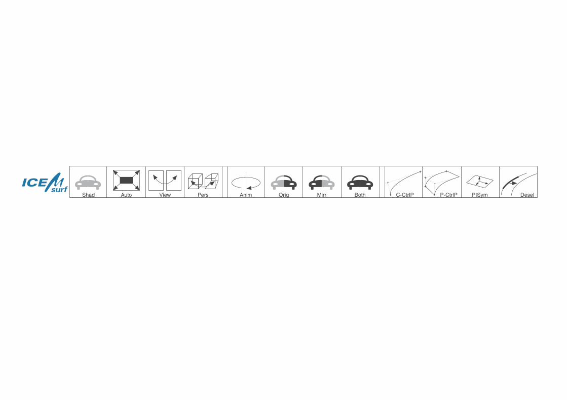
Shad Auto View Pers Anim Orig Mirr Both C-CtrlP P-CtrlP PISym Desel