Embed Size (px)
Citation preview
AC 2008-1753: DEVELOPING AN INDUCTION HEATING SYSTEMLABORATORY WITH DSP MICROPROCESSORS AND POWER ELECTRONICDEVICES
Frank Li, Youngstown State UniversityDr. Li received the B.S. in electrical engineering from Ohio State University, Columbus, OH in1996. He received the Ph.D. degree in electrical engineering from Case Western ReserveUniversity, Cleveland, OH in 2005.
Dr. Li is currently an assistant professor in Department of Electrical and Computer Engineering,Youngstown State University in Ohio. He has 11 years industrial experience. His current researchinterest includes electron spin resonance imaging, EMC, advanced control applications, andapplied magnetic fields in biomedical and spintronic applications.
Theodore Burke, Ajax ToccoTheodore E. Burke is Director of R&D at Ajax Tocco Magnethermic. His positions within thecompany include Service Engineering, Production Engineering and International Engineering.The R&D Dept develops Power Supplies and their controls for Industrial Metal Markets.
Jalal Jalali, Youngstown State UniversityDr. Jalali received the B.S. degree in electrical engineering from University of Missouri,Columbia, MO in 1979. He received the Ph.D. degree in electrical engineering from University ofMissouri, Columbia, MO in 1984.
Dr. jalali is currently the chair and professor of Department of Electrical and ComputerEngineering, Youngstown State University in Ohio. His current research interest includes PowerSystems, Electromagnetics, & Power Electronics & Industrial Controls.
© American Society for Engineering Education, 2008
Page 13.391.1

Developing an Induction Heating System Laboratory with DSP
Microprocessors and Power Electronic Devices
Abstract
This induction heating system laboratory will be integrated into our existing energy conversion
labs for senior students. Students will not only understand how the high alternating current
induces eddy current in the work piece to convert the resistive losses into thermal energy, but
will also observe that the work piece gradually heats up and eventually starts to glow red.
The principle of induction heating is to convert electricity to thermal energy inside a conductive
work piece by using alternating magnetic fields. The energy conversion efficiency is up to 95%
for magnetic materials, and contamination is minimized due to the non-contact heating mode.
Therefore, induction heating has been widely used in steel industries for many years. Most
engineering students are baffled by magnetic field theories since magnetic fields are not
something that they can see, touch or feel except through mathematical equations. To assist
students’ understanding of this energy conversion process, we are developing an induction
heating system laboratory to cover engineering topics in applied magnetic field theories,
communication systems, computer networks, power systems, power electronics, sensors,
embedded systems, and control systems.
In order to generate high strength alternating electromagnetic fields, a switching mode power
supply is utilized to feed high frequency current to the induction coils. The major components of
the switching mode power supply are DC diode bridges, DC filters, DC-AC IGBT invertors,
matching transformers, and capacitor banks. A DSP microprocessor development board is
utilized to generate the Pulse Width Modulation signals to drive IGBT devices. Also, zero-
voltage switching techniques and closed-loop controls are used to control the output power
levels. Infinite impulse filters and fast Fourier transform are built into the DSP microprocessors
to obtain real time frequency spectrum analysis of system harmonics. The temperature of the
work piece can be observed by using an infrared temperature sensor and the measured
temperature can also be fed back to the main DSP microprocessor. The proper output power
level adjustment by the microprocessor creates better temperature profiles in the work piece.
The students are exposed to the commercial finite-element magnetic field analysis software
which provides a visual representation of the magnetic field in the form of flux line plots and
scaled color maps. In our current energy propagation class, we introduce and utilize Infolytica
MagNet® to calculate the magnetic field strength at different frequencies. This software
package can also generate animations of alternating current magnetic fluxes in the work piece.
Introduction
Induction heating is a process by which the temperature of a metal part is raised by the eddy
current losses within the material. It must also be noted that the work piece is only coupled, not
physically connected to the power supply circuitries. The non-contact induction heating
provides a clean energy conversion from electricity to thermal energy that has a few advantages
over the conventional gas heating furnaces, including faster heating time, precise temperature
Page 13.391.2

control capabilities and minimum environmental impacts. Induction heating has been widely
applied to industrial operations such as forging, heat-treating, soldering, hardening, and other
forms of heat transfer. As the oil shortage and global warming become imminent, many new
alternating energy sources such as wind, ocean and solar requires better power management in
the energy conversion1. Engineering students should learn the impacts of their designs to the
environment and induction heating demonstrates such practical energy conversion process.
Figure 1: High frequency power supply system schematics
The schematic of the induction heating system is shown as Fig. 1, the 3-phase 60 Hz
regular industrial standard 480 V supply line is converted to the DC by the Thyristor full bridge.
To provide a constant high power factor, the line chock Ls and optional filter capacitors are used
to filter high frequency components from the power supply. The inductor LDC and capacitor
CDC filter section eliminates the voltage ripples from the DC Bridge and prevents high
frequency component feedbacks from the inverter section. The insulated gate bipolar transistors
(IGBT) are ideal power electronic devices for high current and high voltage applications.
Because the load section is inductive, in the inverter section IGBTs, the pair P+ and P-, N+ and
N- must be turned on/off simultaneously to ensure a current path at any given moment. The
IGBTs are switched at zero power supply output voltage crossing to minimize the electrical
stresses on power electronic devices. The IGBT gate drives are not shown in this schematic, gate
signals created by the main DSP microprocessor controls the on/off of the IGBT devices.
The series inductance LSE, the capacitor bank, and the induction coil form a series-
parallel resonant circuit that generates high frequency current in the inductor coil. A typical
Page 13.391.3

induction heating has an operating frequency closed to the resonant frequency, where the load
impedance is close to the minimum and the current through the inductor is at the maximum2.
The alternating current in the induction coil generates high strength magnetic fields and induces
the eddy currents in the metal work piece.
Magnetic field simulation using finite element software
Students are asked to simulate the magnetic field distributions in the work piece and the
surrounding air space and the inductor coppers. A 3-D solid model is generated based on the
actual metal work piece and inductor dimensions. Fig. 2 shows one sample metal work piece
and the 2-D meshes of the solid model. The finite element method (FEM) is an excellent way to
solve partial differential equations over complex domains3-6
. The solutions of the differential
equations are approximations; the accuracies are depending on the precision requirements. By
use of FEM, the smaller the element size will result in higher accuracy. However, FEM software
is demanding large memory especially when the element size is small and the number of element
is large. To increase the accuracy of the FEM simulation, the element size in the conductor is
kept the smallest, while the size of the element in the air space is the largest.
Figure 2: 3-D induction heating model and 2-D meshes
Students will learn how to balance the memory usages and the accuracies of the models. The
Infolytica®
software selects the size of the mesh triangles automatically to minimize the memory
usage and guarantees the accuracies of the simulations. The metal work piece and the induction
coil are surrounded by air space. The dimension of the air space is much larger compare to the
induction coil, such that the magnetic fields on air space boundaries are considered to be zero.
Page 13.391.4
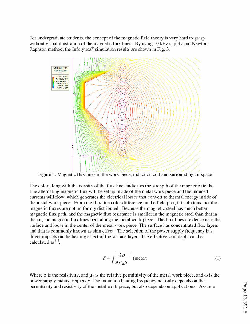
For undergraduate students, the concept of the magnetic field theory is very hard to grasp
without visual illustration of the magnetic flux lines. By using 10 kHz supply and Newton-
Raphson method, the Infolytica®
simulation results are shown in Fig. 3.
Figure 3: Magnetic flux lines in the work piece, induction coil and surrounding air space
The color along with the density of the flux lines indicates the strength of the magnetic fields.
The alternating magnetic flux will be set up inside of the metal work piece and the induced
currents will flow, which generates the electrical losses that convert to thermal energy inside of
the metal work piece. From the flux line color difference on the field plot, it is obvious that the
magnetic fluxes are not uniformly distributed. Because the magnetic steel has much better
magnetic flux path, and the magnetic flux resistance is smaller in the magnetic steel than that in
the air, the magnetic flux lines bent along the metal work piece. The flux lines are dense near the
surface and loose in the center of the metal work piece. The surface has concentrated flux layers
and that is commonly known as skin effect. The selection of the power supply frequency has
direct impacts on the heating effect of the surface layer. The effective skin depth can be
calculated as7-8
,
(meter)2
0µµω
ρδ
R
= (1)
Where ρ is the resistivity, and µR is the relative permittivity of the metal work piece, and ω is the
power supply radius frequency. The induction heating frequency not only depends on the
permittivity and resistivity of the metal work piece, but also depends on applications. Assume
Page 13.391.5

the flux lines generated by the induction coil passes through the metal work piece entirely, based
on the Ampere’s law the current generated inside the work piece is N times the current in the N-
turn induction coil. Therefore, the induction heating coil acts like a current transformer. The
higher the current in the induction coil, the higher the current is in the metal work piece, and
higher energy transferred to thermal energy.
IGBT gate signal generations using the DSP microprocessor
In a typical industrial plant, noise sources, such as wielding machine, motor drives, heating
lamps and radios, can destroy the integrity of the analog signals. By going to digital control, the
feedback and control signals can be sent over a longer distance without distortions; filtering the
unwanted noises can be easily done by adding a digital IIR filter; perfect copies of the signals
can be transmitted on various networks; programmability allows future easy updates and
improvements; memory cards can be added for data acquisition and storages; real time digital
sampling enables early fault detections. The size of the DSP processor is greatly reduced and
more features are integrated on the same chip to save valuable board space. The DSP
microprocessors are optimized for signal processing applications compared to the early general
purpose microprocessors. Therefore, it is ideal for the control of the power supply in real time.
The embedded hardware multiplier and divider increase the speed of the signal processing, and
the build-in PMW generator provides direct control from the main processor.
The Texas Instrument TMS320 platform evaluation boards will be used as the main control
board. The main clock of the DSP microprocessor is 200 MHz, the memory includes 320K RAM
and 32K ROM with external memory supports. The on-chip ROM can eliminate the requirement
of expensive non-volatile memory and store crucial data for the system. The main
microprocessor also has vital on-board peripherals, such as I2C, CAN and SPI communication
ports. By using standard Ethernet driver the boards can be connected to the internet, which
enables remote monitoring of the power supply operations. The programming will be done by TI
code composer studio. The current through the induction coil is measured using current
transformer and feedback to a 16-bits A/D converter and connect to the DSP processor. The
voltage across the capacitor station is sampled and feedback to the DSP processor to calculate
the power supply output power in real time. For example, consider the sampling data from the
feedback signals such as line voltage, induction coil current, and capacitor voltage. The
microprocessor must read the data before new data arrives; otherwise, the data will be lost.
Because the power supply runs at 10 kHz and above, it is not necessary to update readings every
0.1 ms. Therefore, the display of the power, voltage, and current readings of the power supply
can be updated every 0.1 second. The data is buffered and to be processed later. Therefore, the
real time display of the feedback signals is a soft real time event. The difficulty of designing
real-time power supply control systems depend upon the frequency of the microprocessor. With
a 200MHz processor, there are 20,000 cycles to respond to a 0.1 millisecond deadline. The
microprocessor has embedded real-time operation systems (RTOS), which are designed to give
priority to real time tasks. The design will be based on worst-case scenario and considers all
possible interrupts9-13
.
The IGBTs are rated at 1200V and capable of carrying 1000 Amps with switching frequency of
15 kHz. The n-channel and p-channel IGBT device require unique gate-source voltage control
Page 13.391.6

pulses, which are generated by the IGBT gate drives. The IGBT drive board receives the PWM
signals from the main control board through optical cable and output the pulse waveforms that
are shown in Figure 4. It is vital that the IGBT pairs have the same turn on/off pulse at exactly
the same time to maintain the inductive current in the induction heating coil.
P
N
Figure 4: IGBT gate signal generated by the gate drivers
Circuit simulations and field measurement
The PSPICE computer simulations help students gain knowledge of the circuit before building
the circuits and understand the system design process better. Unlike the standard resistors,
capacitors and inductors, in real world system design, the values of the capacitance, inductance
and resistance have to be measured using LCR meters.
To model the induction heating circuit, the induction coil with load can be approximately
modeled as a series inductor and resistor. To simplify the circuit, the resistance of the capacitor
band and series inductor will be ignored. The impedance of the load can be calculated as,
( ) ( )
111/1
1/11load
RLjCj
CjLjRLjZ SE
++
++=
ωω
ωωω (2)
From the above equation, the load impedance depends on the power supply frequency, at a
resonant frequency the impedance is a real number. In the real world applications, the capacitor Page 13.391.7

bank will be chosen based on the inductance of the induction heating coil to have a resonance
frequency close to the power supply output frequency.
(a)
(b)
Figure 5: (a) simplified load circuit, R1 and L1 represent the resistance and inductance of the
metal work piece and the induction coil (b). PSPICE simulation results show the series inductor
current peak is around 600 Amps
Students are asked to use a 10 uH inductor and 1 Ω resistor to model the induction coil and the
metal work piece. The capacitance of the capacitor bank and the inductance of the series inductor
are to be designed to have a resonance frequency close to 10 kHz. A pulse generator is used to
simulate the output of the DC to AC inverter that has square wave outputs.
Time
0s 100us 200us 300us 400us 500usV(LSE:1) -I(LSE)
-600
-400
-200
0
200
400
600
Page 13.391.8

Because there are no standard PSPICE models for the IGBT and Thyristor, the simulation of the
AC to DC full bridge converter and the DC to AC full bridge inverter can be done by creating
customized PSPICE parts14-16
.
Induction heating of a steel bar
Students are usually baffled with the idea of magnetic field and the complex mathematical
equations. By designing and building the induction heating system, students will see the drastic
change of a steel bar, which changes from dull dark color to red by the magnetic field. The high
frequency power supply is shown in Figure 6 (a). The power supply has three analog meters that
display the percentages of the output power, capacitor bank voltage, and the output current.
Water cooling is required for power supply normal operations, to remove internal heats from
transmission lines, output transformer and power electronic devices.
(a)
Page 13.391.9

(b)
Figure 6: (a) the high frequency power supply is capable of supplying 50 kW, 1,600 Amps, 3-10
kHz (b). A steel bar is exiting the induction heating coil
The induction heating coils are typically designed to have many turns. Therefore, the current on
the metal work piece, which has only one shorted turn, can be very large. The temperature of the
steel bar rises very rapidly and the typical heating time of a small diameter steel bar is around 1-2
seconds. An infrared sensor may provide a temperature feedback signal for close-loop control
purposes.
Conclusion
This paper presented a senior electrical engineering lab that converts electricity to thermal
energy through the induction heating processes. The lab will prepare senior students for their
capstone design course and help students grasp difficult topics in magnetic field theory, power
electronics, digital signal processing, and advanced digital control theory.
Reference
1. Nehrir, M. Hashem; Wang, Caisheng; Guda, S.R., "Alternative Energy Distributed Generation: Need for Multi-
Source Operation," Power Symposium, 2006. NAPS 2006. 38th North American , vol., no., pp.547-551, Sept.
2006
2. F. Li, J. Jalali, R. Foulkes, "Linear Quadratic Tracking Controller Design to improve High Frequency Power
Supply Performance"; 61st American Power Conference proceedings, (1999)
3. J. P. Webb, and B. Forghani, “Allowing for arbitrary material models in a 3D finite-element method for
magnetic field analysis”, Non-linear Electromagnetic Systems, Studies in Applied Electromagnetics and
Mechanics, Vol. 18, 2000, pp. 405-408.
Page 13.391.10

4. J.P. Webb, “Application of the finite element method to electromagnetic and electrical topics”, Reports on
Progress in Physics, Vol. 58, Dec. 1995, pp. 1673-1712.
5. J.P. Webb, and B. Forghani, “A T-Omega method using hierarchal edge elements”, IEE Proceedings, Sci. Meas.
Technol., vol. 142, no. 2, Mar. 1995, pp. 133-141.
6. M. Feliachi and G. Develey, “Magneto-thermal behavior finite element analysis for ferromagnetic materials in
induction heating devices,” IEEE Trans. Indust. Applicat. Syst., vol. 27, pp. 5235–5237, Nov. 1997.
7. F. Dughiero, M. Forzan, and S. Lupi, “Solution of coupled electromagnetic and thermal problems in induction
heating applications,” Inst. Elect. Eng. Comput. Electromagn., no. 420, pp. 301–305, 1996.
8. I.-G. Kwak and S.-Y. Hahn, “Design sensitivity of transient electro thermal problems for the specific
temperature distribution,” IEEE Trans. Magn., vol. 36, pp. 1148–1152, July 2000.
9. Zhang Jinlong; Chen Houjin, "Integrating RTOS into SHARC DSP to implement parallel processing," Signal
Processing, 2004. Proceedings. ICSP '04. 2004 7th International Conference on , vol.1, no., pp. 124-127 vol.1,
31 Aug.-4 Sept. 2004
10. Garate, I.; Carrasco, R.A.; Bowden, A.L., "An integrated digital controller for brushless AC motors using a DSP
microprocessor," Power Electronics and Variable-Speed Drives, Third International Conference on , vol., no.,
pp.249-252, 13-15 Jul 1988
11. Barnwell, T.P., III, "Real-time signal processing using DSP microprocessors - an undergraduate capstone
design course at Georgia Tech," Digital Signal Processing Workshop, 2004 and the 3rd IEEE Signal Processing
Education Workshop. 2004 IEEE 11th , vol., no., pp. 6-9, 1-4 Aug. 2004
12. Chern, T.-L.; Wong, J.-S., "DSP based integral variable structure control for DC motor servo drivers," Control
Theory and Applications, IEE Proceedings - , vol.142, no.5, pp.444-450, Sep 1995
13. Chang, B.C.; Chunlong Hu; Ilg, M., "Design and DSP microprocessor implementation of digital sinusoidal
tracking controllers," American Control Conference, 2005. Proceedings of the 2005 , vol., no., pp. 4947-4952
vol. 7, 8-10 June 2005
14. Frisina, F.; Leonardi, C.; Raciti, A.; Torrisi, S., "Physics based model of punch through IGBTs simulated by
PSpice," Computers in Power Electronics, 1998. 6th Workshop on , vol., no., pp.27-35, 1998
15. Chindris, G.; Pop, O.; Alin, G.; Hurgoi, F., "New PSPICE model for power MOSFET devices," Electronics
Technology: Concurrent Engineering in Electronic Packaging, 2001. 24th International Spring Seminar on ,
vol., no., pp.158-162, 2001
16. Muhamad, N.D.; Shafie, A.J., "An approach to Pspice-aided control loop design of DC-DC converter systems,"
Power Engineering Conference, 2003. PECon 2003. Proceedings. National , vol., no., pp. 121-126, 15-16 Dec.
2003
Page 13.391.11