Embed Size (px)
Citation preview

8/9/2019 An Induction Heating
http://slidepdf.com/reader/full/an-induction-heating 1/14
APPLICATION NOTE
INDUCTION HEATING
Jean Callebaut, Laborelec
December 2011
ECI Publication No Cu0123
Available from www.leonardo-energy.org/drupal/node/1693

8/9/2019 An Induction Heating
http://slidepdf.com/reader/full/an-induction-heating 2/14
Publication No Cu0123
Issue Date: December 2011
Page i
Document Issue Control Sheet
Document Title: Application Note – Induction Heating
Publication No: Cu0123
Issue: 02
Release: December 2011
Author(s): Jean Callebaut
Reviewer(s): Egbert Baake
Document History
Issue Date Purpose
1 February
2007
Initial publication
2 December
2011
Adapted for adoption into the Good Practice Guide
3
Disclaimer
While this publication has been prepared with care, European Copper Institute and other contributors provide
no warranty with regards to the content and shall not be liable for any direct, incidental or consequential
damages that may result from the use of the information or the data contained.
Copyright© European Copper Institute.
Reproduction is authorized providing the material is unabridged and the source is acknowledged.

8/9/2019 An Induction Heating
http://slidepdf.com/reader/full/an-induction-heating 3/14
Publication No Cu0123
Issue Date: December 2011
Page ii
CONTENTS
Summary ........................................................................................................................................................ 1
Physical principles .......................................................................................................................................... 2
Electromagnetic induction ...................................................................................................................................... 2
The Joule-effect ...................................................................................................................................................... 3
Penetration depth .................................................................................................................................................. 3
Induction Installations .................................................................................................................................... 5
General aspects ...................................................................................................................................................... 5
Power supply and generators ................................................................................................................................. 5
Inductors ................................................................................................................................................................. 5
Properties of induction heating ...................................................................................................................... 6
Power Transfer: simplified calculation ................................................................................................................... 6
Electrical efficiency ................................................................................................................................................. 7
Power factor ........................................................................................................................................................... 7
Characteristics of induction heating ....................................................................................................................... 7
Industrial Applications .................................................................................................................................... 9
Melting of metals by means of induction crucible furnaces .................................................................................. 9
Brazing 9
Inductive hardening of steel ................................................................................................................................... 9
Conclusions ................................................................................................................................................... 11
References .................................................................................................................................................... 11

8/9/2019 An Induction Heating
http://slidepdf.com/reader/full/an-induction-heating 4/14
Publication No Cu0123
Issue Date: December 2011
Page 1
SUMMARY
Induction heating is used for the direct heating of electrically conducting materials. The primary advantage is
that the heat is generated within the material itself, giving very fast cycle times, high efficiency, and the
potential for localized heating. On the downside, because of the desired coupling between inductor and load,
there are restrictions on the size and geometry of the work piece. However, there are many applications in thefield of heating or melting of metals.
8/9/2019 An Induction Heating
http://slidepdf.com/reader/full/an-induction-heating 5/14
Publication No Cu0123
Issue Date: December 2011
Page 2
PHYSICAL PRINCIPLES
The principle of induction heating is mainly based on two well-known physical phenomena:
1. Electromagnetic induction
2. The Joule effect
ELECTROMAGNETIC INDUCTION
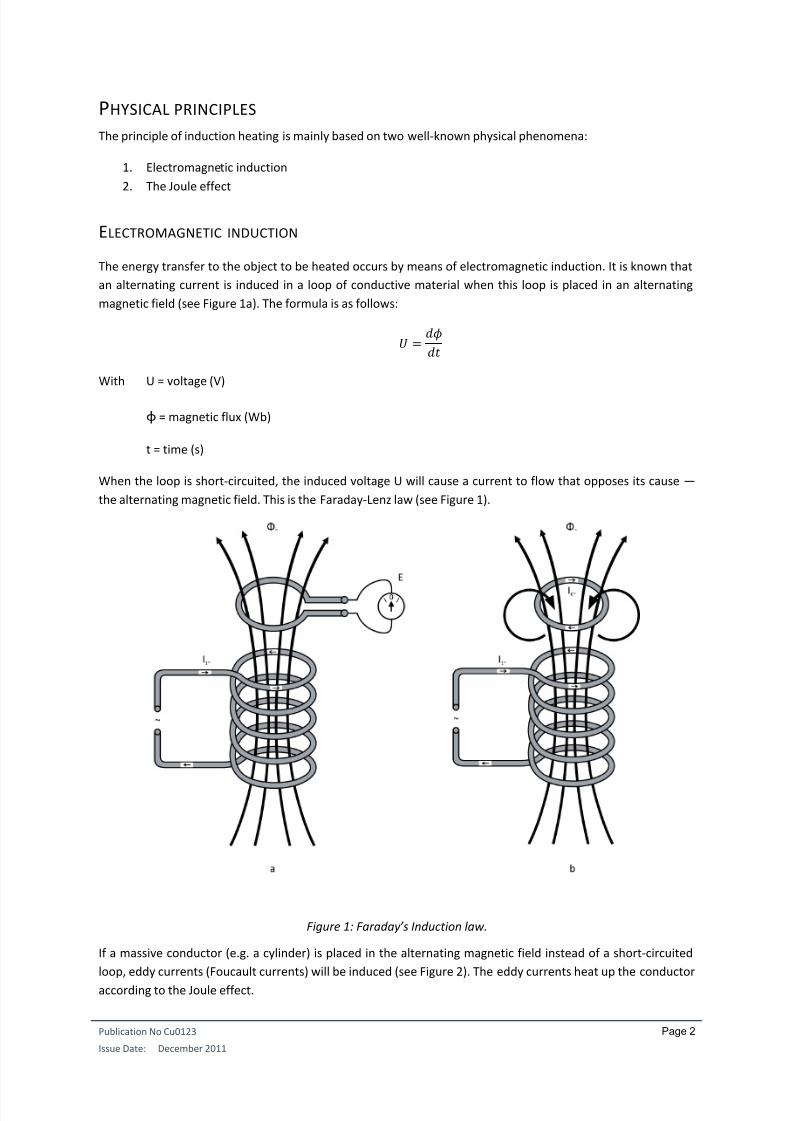
The energy transfer to the object to be heated occurs by means of electromagnetic induction. It is known that
an alternating current is induced in a loop of conductive material when this loop is placed in an alternating
magnetic field (see Figure 1a). The formula is as follows:
With U = voltage (V)
ɸ = magnetic flux (Wb)
t = time (s)
When the loop is short-circuited, the induced voltage U will cause a current to flow that opposes its cause —
the alternating magnetic field. This is the Faraday-Lenz law (see Figure 1).
Figure 1: Faraday ’s Induction law.
If a massive conductor (e.g. a cylinder) is placed in the alternating magnetic field instead of a short-circuited
loop, eddy currents (Foucault currents) will be induced (see Figure 2). The eddy currents heat up the conductor
according to the Joule effect.

8/9/2019 An Induction Heating
http://slidepdf.com/reader/full/an-induction-heating 6/14
Publication No Cu0123
Issue Date: December 2011
Page 3
Figure 2: Induction of Eddy Currents.
Remark: In many practical applications, a solenoid or coil is used to generate the magnetic field. However, the
applications of induction heating are not limited to the form of inductor.
THE JOULE-EFFECT
When a current I [A] flows through a conductor with resistance R [], the power is dissipated in the conductor.
In most applications of induction heating, the determination of resistance R is not a simple matter due to the
non-uniform distribution of current in the conductor.
PENETRATION DEPTH
A general characteristic of alternating currents is that they are concentrated on the outside of a conductor.
This is called the skin effect . In addition, the eddy currents induced in the material to be heated are greater on
the outside and diminish towards the centre. Thus, most of the heat is generated on the outside. The skin
effect is characterized by its so-called penetration depth . Penetration depth is defined as the thickness of the
layer, measured from the outside, in which 87% of the power is developed (Figure 3).
Figure 3: Penetration depth.
The penetration depth can be deduced from Maxwell’s equations. For a cylindrical load with a diameter that is
much bigger than , the formula is as follows:

8/9/2019 An Induction Heating
http://slidepdf.com/reader/full/an-induction-heating 7/14
Publication No Cu0123
Issue Date: December 2011
Page 4
With ρ = resistivity [Ωm]
µ = magnetic permeability [H/m] (µ = µ0 . µr)
f = frequency [Hz]
On the one hand, we see that the penetration depth depends on the characteristics of the material to be
heated (, ) while on the other hand, it is also influenced by the frequency. This frequency dependence offers
a possibility to control the penetration depth.
The following table gives an idea of the order of magnitude of .
Table 1: Penetration depths
in [mm] Steel
20 °C
Steel
20 °C
Copper
20 °C
Copper
900 °C
Graphite
20 °C
[µ.m] 0.16 0.16 0.017 0.086 10
r [-] 40 100 1 1 1
Frequency
50 Hz 4.50 2.85 9.31 20.87 225.08
100 Hz 3.18 2.01 6.58 14.76 159.15
1 kHz 1.01 0.64 2.08 4.67 50.33
10 kHz 0.32 0.20 0.66 1.48 15.92
100 kHz 0.10 0.06 0.21 0.47 5.03
1 MHz 0.03 0.02 0.07 0.15 1.59
As can be derived from the formula above, the penetration depth is inversely proportional to the square root
of r .
For non-magnetic materials like copper or aluminium, the relative magnetic permeability is r=1.
Ferromagnetic materials (such as iron and many types of steel) on the contrary, have a r-value that is much
higher. Therefore, these materials generally show a more explicit skin effect (smaller ).
The magnetic permeability of ferromagnetic materials depends strongly on the composition of the materials
and on the circumstances (temperature, magnetic field intensity, saturation). Above the Curie temperature, r
suddenly drops again to r=1, which implies a rapid increase of the penetration depth.

8/9/2019 An Induction Heating
http://slidepdf.com/reader/full/an-induction-heating 8/14
Publication No Cu0123
Issue Date: December 2011
Page 5
INDUCTION INSTALLATIONS
GENERAL ASPECTS
The inductor and the load behave as an inductive load and are compensated with capacitors. A frequency
converter feeds the entirety with a single-phase current at the desired frequency.
An induction installation also contains a cooling system (for the frequency converter and inductor), a transport
system, and the necessary control and measuring apparatus.
POWER SUPPLY AND GENERATORS
The electrical supply can occur in different ways, depending on the frequency at which the installation has to
work.
50Hz-installations:
The compensated load is directly connected to the transformer. The transformer can be regulated so that the
current can be adjusted to the impedance of the load.
Frequency converters with thyristors:
Efficiency: 90-97%
Frequency range: 100 Hz – 10 kHz
Power range: up to 10 MW
Frequency converters with transistors:
Efficiency: 75-90%
Frequency range: up to 500 kHz
Power range: up to 500 kW
Frequency converters with vacuum tubes:
Efficiency 55-70%
Frequency range: up to 3000 kHz
Power range: up to 1200 kW
INDUCTORS
In most applications, the inductor consists of a hollow copper tube. The simplest, most commonly applied
configuration consists of one or more windings that surround the work piece. However, the inductor can be
placed in many configurations, depending on the application.
The inductor is usually made of copper in order to limit electric losses. Nevertheless, the inductor is in almost
all cases internally water-cooled.

8/9/2019 An Induction Heating
http://slidepdf.com/reader/full/an-induction-heating 9/14
Publication No Cu0123
Issue Date: December 2011
Page 6
PROPERTIES OF INDUCTION HEATING
POWER TRANSFER: SIMPLIFIED CALCULATION
The load of an induction installation is heated as a result of the Joule effect due to induced eddy currents. The
simple formula P=R I² cannot be used because the distribution of the currents over the conductor is not
uniform.
However, starting from:
(1)
And knowing that:
(2) with πd the periphery of the inductor
(3)
(4)
We can insert (3) in (2) and then (2) and (4) in (1) and get, after adding F and C:
√
With d = diameter of the cylinder [m]
h = height of the cylinder [m]
H = magnetic field intensity [A/m]
ρ= resistivity [Ωm]
µ0 = magnetic permeability of vacuum (4π.10-7
H/m)
µr = relative permeability
f = frequency [Hz]
C = coupling factor
F = power transmission factor
The last two terms in the formula are correction factors:
F (power transmission factor):
o Takes into account the relation between the penetration depth and the external dimensions
of the load. F depends on the geometry of the load.
C (coupling factor):
o Corrects for the relative dimensions of the inductor and the load. The correction is smaller as
the inductor is longer and the air gap between the inductor and the load is smaller.
Conclusions resulting from these formulas:

8/9/2019 An Induction Heating
http://slidepdf.com/reader/full/an-induction-heating 10/14
Publication No Cu0123
Issue Date: December 2011
Page 7
The power can be increased by an increase in the magnetic field intensity H. This means increasing
the number of ampere-windings of the inductor.
An increase of the frequency only leads to a relative small increase in the power. Moreover, the losses
in the supply increase and the penetration depth gets smaller.
Material characteristics play an important role ( and especially r). For ferromagnetic materials the
added power drops when the Curie temperature is exceeded (r=1 if T>TCurie).
ELECTRICAL EFFICIENCY
The electrical efficiency is defined as follows:
With P = power, induced in the load
Pi = power, dissipated in the inductor
Efficiency is also strongly influenced by the relation of the diameter to penetration depth (in the case of a
cylindrical load). Finally, the design of the inductor is also important and the following points of attention
apply:
For the inductor, use a material with low resistance. Usually, electrolytic copper is applied
Use an inductor with a small distance between the windings
Provide a good connection between the inductor and the load (limitation of the air gap and make the
inductor sufficiently long).
POWER FACTOR
The whole of the inductor and the load usually represents an important reactive power. On the one hand,
there is the air gap between the inductor and the load. On the other, the load itself also has an inductive
character, depending on the relation d/ (in case of a cylinder).
The power factor of the inductor and the load usually lies around 0.05-0.6. Compensation by means of
condensers is required in all cases.
CHARACTERISTICS OF INDUCTION HEATING
Technical process
Because of the high power density, an induction installation can be compact and realize a quickheating
Induction offers the possibility of reaching very high temperatures
Induction heating can be applied to specific area of workpiece
Induction installations are suited for automation
Energy consumption
Induction installations generally have good efficiency although this efficiency also depends upon the
characteristics of the material to be heated
A significant portion of the heat losses can be recuperated
Quality

8/9/2019 An Induction Heating
http://slidepdf.com/reader/full/an-induction-heating 11/14
Publication No Cu0123
Issue Date: December 2011
Page 8
Extreme purity is possible by working in a vacuum or in inert atmospheres
The precise location of heating can be determined accurately
The heating can be regulated precisely
Environment and working conditions
No production of flue gasses
Limitations
An induction installation usually implies a major investment that must be considered and compared
to alternative heating techniques
Simple shapes are preferred for induction heating

8/9/2019 An Induction Heating
http://slidepdf.com/reader/full/an-induction-heating 12/14
Publication No Cu0123
Issue Date: December 2011
Page 9
INDUSTRIAL APPLICATIONS
Typical applications of induction are the melting of metals, the heating of metals for design, brazing and
welding, and all sorts of surface treatments such as hardening. However, by using electric conductive
recipients (e.g. graphite), other materials such as glass can also be heated.
MELTING OF METALS BY MEANS OF INDUCTION CRUCIBLE FURNACES
An induction crucible furnace essentially consists of a crucible (with refractory lining) which is surrounded by
the induction coil. The material to be melted is placed inside this crucible. The coil is water-cooled and is
surrounded by an iron core, in order to improve magnetic coupling.
There are applications at 50Hz as well as mid-frequency applications. The power range (up to 10MW and
more) and the specific powers (up to 1200 kW/ton) are extremely high. The melting can therefore occur very
quickly.
Low-frequency induction crucible furnaces (50Hz) are usually applied for big applications (large power and
large capacity). Mid-frequency furnaces are generally used in smaller applications. They offer more flexibilityand are more compact. In general, there is a trend towards using mid-frequency furnaces at the expense of
low-frequency furnaces.
BRAZING
Brazing is an assembly technique where two pieces are joined together by means of a third material that is
brought to its melting temperature. In the connection zone, both pieces are heated to a temperature higher
than the melting temperature of the third material.
Induction is frequently applied because of the precise localization of the heating. Moreover, the heating
happens very quickly which means that any oxidation, structural, or compositional changes can be controlled.Brazing under inert an atmosphere is possible. Induction heating is suited for high production speeds on
automatic production lines.
INDUCTIVE HARDENING OF STEEL
Steel with a carbon percentage of at least 0.3% is qualified for surface hardening. The work piece is heated to
approximately 900 °C after which it is quenched. This technique is used for the hardening of gear wheels,
crankshafts, valve stems, saw blades, spades, rails, and many other items.
The inductive process has the advantage that the treatment can be localized very accurately. Moreover, the
chemical composition of the surface layer does not change, as is the case for other surface hardening
techniques. Because of the selective heating, less energy is required than for a complete heating of the
product, and distortion is avoided. Very high energy densities (1.5 to 5kW/cm²) and short treatment times (2
seconds) are typical for inductive hardening.
Figure 4 shows some realizations of inductors. Some inductors are equipped with a spraying system that
enables quenching the work piece immediately after heating.

8/9/2019 An Induction Heating
http://slidepdf.com/reader/full/an-induction-heating 13/14
Publication No Cu0123
Issue Date: December 2011
Page 10
Figure 4: Inductors for hardening.
Inductive hardening is especially well suited for automated production processes with sufficient production
volume. A constant, high production quality can be reached with induction heating. The energy consumption
and the production losses are lower than with conventional techniques.

8/9/2019 An Induction Heating
http://slidepdf.com/reader/full/an-induction-heating 14/14
Publication No Cu0123
Issue Date: December 2011
Page 11
CONCLUSIONS
This application guide demonstrates the advantages of a less conventional heating technique. As explained
throughout this document, the primary advantage of induction heating is that the heat is generated within the
material to be heated. This results in a very quick response, good efficiency, and local heating possibilities.
On the downside, restrictions concerning size and geometry have to be taken into account because of the
desired coupling between inductor and load. However, there are many applications possible in the field of
heating or melting of metals.
REFERENCES
[1] V. Rudnev, D. Loveless, R. Cook, M. Black, Handbook of Induction Heating, Marcel Dekker, New York,
2003.
[2] P. A. Davidson, An Introduction to Magnetohydrodynamics, Cambridge University Press, Cambridge,
2006.
[3] Proceedings of the 5th
International Symposium on Electromagnetic Processing of Materials, The Iron
and Steel Institute of Japan, 2006.
[4] A.C. Metaxas, Foundations of Electroheat. A Unified Approach, John Wiley & Sons, Chichester, 1996
[5] Starck, A. v.; Mühlbauer, A.; Kramer, C.: Handbook of Thermoprocessing Technologies. Vulkan-Verlag,
Essen 2005