Embed Size (px)
Citation preview

Designing with the Nios II Processor and SOPC Builder
Exercise Manual
Software and Hardware Requirements to Complete All Exercises
Software Requirements: Quartus II 8.1 ModelSim 6.4g Nios II 8.1 Altera university IP 8.0 Hardware Requirements:
This lab guide is set up to allow you to use the following boards: Nios Development Kits: DE2

Exercise Manual Designing with the Nios II Processor and SOPC Builder
2
Software and Hardware Requirements to Complete All Exercises ..............................................................1
Lab 0: Preparations for labs ..........................................................................................................................3
Lab 1: Creating a NiosII Processor System...................................................................................................5
Lab 2: Software Flow..................................................................................................................................18
Lab 3: Basic Led & Switches......................................................................................................................28
Lab 4: Basic LCD........................................................................................................................................30
Lab 5: Basic Ps2 - Keyboard.......................................................................................................................37
Lab 5: Adding Pll to Nios II Processor System...........................................................................................52

Exercise Manual Designing with the Nios II Processor and SOPC Builder
3
Lab 0: Preparations for labs

Exercise Manual Designing with the Nios II Processor and SOPC Builder
4
Objectives:
Over the course of the lab today, you will create a hardware system and run some software code on it. As the lab progresses, you will continue to modify your system to incorporate new hardware features as you learn about them in class. This lab guide is set up to allow you to use any one of the following development kits, so, some written steps will pertain to one type of board; other steps to another type of board. The kits fall into two main categories as shown below:
Nios II Processor Development Kits:
DE2
Hardware and driver set up:
• Fallow the instructions on the flowing PDF to test your board, and making sure you have all it takes to start working.
Software set up:
• Fallow the instructions on the AVI movie (nios_tut\movies\1.avi) to test your board, and making sure you have all it takes to start working.
• Locate your project in a path witch does not have spaces in it!! o “C:\altera\70\quartus\My_project” – OK o “C:\altera\70\quartus\My project” – WORNG! o “C:\altera\70\quartus\הפרויקט שלי” – WORNG!

Exercise Manual Designing with the Nios II Processor and SOPC Builder
5
Lab 1: Creating a NiosII Processor System
*this section does refer to actual programs given to you, all the codes and screen shoots are located in the “DOC” folder. The name of the QURARTUS project is:

Exercise Manual Designing with the Nios II Processor and SOPC Builder
6
Building your embedded system:
1. Crate a QUARTUS project.
2. Add an empty BDF file.
3. Go to assignments->import assignments and select “DE2_pin_assignments” from the lab folder.
4. Start SOPC Builder from Tools => SOPC Builder… and enter the system name, niosII, when the next window pops up. You can choose VHDL or Verilog (whichever you prefer) as the implementation language. The blank SOPC builder window will open.
1. Set the Device Family to match the FPGA you are using:
2.avi

Exercise Manual Designing with the Nios II Processor and SOPC Builder
7
Exercise Manual Designing with the Nios II Processor and SOPC Builder
8
2. From the left hand window pane select Nios II Processor and click Add. Select Nios II/s for the processor core. Select DSP Block as the Hardware Multiply option for all Stratix & Stratix II boards, Embedded Multipliers for all Cyclone II boards or Logic Elements for Cyclone boards.

Exercise Manual Designing with the Nios II Processor and SOPC Builder
9
3. Click on the Caches and Tightly Coupled Memories tab. Set the value to be 4KB.
4. Click Finish. This will add it to the SOPC Builder system.

Exercise Manual Designing with the Nios II Processor and SOPC Builder
10
5. Now, click on the JTAG Debug Module tab. Select the JTAG Target Connection Download Level 1 option. This will provide us with all the debug options listed on that tab.
6. Click Finish. This will add it to the SOPC Builder system.

Exercise Manual Designing with the Nios II Processor and SOPC Builder
11

Exercise Manual Designing with the Nios II Processor and SOPC Builder
12
7. From the left hand window pane find the JTAG UART from the Interface Protocols > Serial folder and click Add. Accept the defaults. (The screen should appear as shown .) Click Finish. This will add it to the SOPC Builder system.

Exercise Manual Designing with the Nios II Processor and SOPC Builder
13
8. Locate the System ID Peripheral from the Peripherals > Debug and Performance folder in the pick list, and Add it to your system. (Note: it is recommended that every SOPC Builder design that you create has a system ID peripheral!) Click Finish. This will add it to the SOPC Builder system.
*Rename the device to “Sysid”.

Exercise Manual Designing with the Nios II Processor and SOPC Builder
14
8. Add Sram memory:
Locate the Sram from the University... folder in the pick list, and Add it to your system.
Click Finish. This will add it to the SOPC Builder system.

Exercise Manual Designing with the Nios II Processor and SOPC Builder
15
9. Add Ps2, LCD, PIO: Accept all defaults, Click Finish. This will add it to the SOPC Builder system. Select PIO “output only” for led usage only, or “output and input” (not bidirectional) for led and switches,
Final configuration:
Toggling Avalon Bus Connections:
Click your mouse on the appropriate dots with in connectivity diagram in order to toggle the connections as shown below: (Note: the connected state is solid; while the disconnected state is white.)
Next step is to press SYSTEM->“Auto assign base address” .

Exercise Manual Designing with the Nios II Processor and SOPC Builder
16
10. Next, click Generate. SOPC Builder will now create the parameterized SOPC system.
Note: If you happen to receive a warning message in SOPC Builder that prevents you from generating the system, check to make sure that all the peripherals are connected to clk_0.
If setting clk_0 does not solve your problem, you may have to close SOPC Builder and then re-open it again in order to register the change you just made.
11. After SOPC Builder has finished generating your embedded sub-system:
a. open the project-> topl level schematic in Quartus II using p->Open so that you can add the system to your project.
12. Rgiht click on the symble->Generate pins, change the pins name to the names shown. 13. Zoom in or out in the schematic, as needed, using the magnifying glass utility. The
schematic editor should resemble the following: (led only)

Exercise Manual Designing with the Nios II Processor and SOPC Builder
17
schematic editor should resemble the following: (led and switches)

Exercise Manual Designing with the Nios II Processor and SOPC Builder
18
Lab 2: Software Flow *this section does not refer to actual programs given to you, all the codes and screen shoots are for illustration only. DONOT TRY TO FINED THEAXACT CODE IN THE MOVIES OR TEXT FILES – ITS NOT THERE!

Exercise Manual Designing with the Nios II Processor and SOPC Builder
19
1. You will now download the Nios II FPGA design created in the previous lab to the Nios development board. Within Quartus II , select the Programmer from the Tools menu. (If the .sof file for
your project does not populate the File field then click on the Add File button . Then select file niosII_lab.sof and click Open.)
2. Tick the Program/Configure checkbox for that .sof file, and then click the Start
Programming icon . If the Start Programming button is not enabled, make sure you Hardware Setup field (at
the top of the Programmer window) reads USB-Blaster or Byteblaster. If not, click on the Hardware Setup button and choose USB-Blaster or Byteblaster from the drop-down menu, and click Close.
3. Launch the Nios II IDE from SOPC Builder (see Tools > Nios II IDE). Select OK if the Workspace Launcher dialog box appears.
4. Go to the Nios II IDE workbench, create a new software project by selecting New->Project from the File menu. Select Nios II C/C++ Application, and press Next.
Exercise Manual Designing with the Nios II Processor and SOPC Builder
20
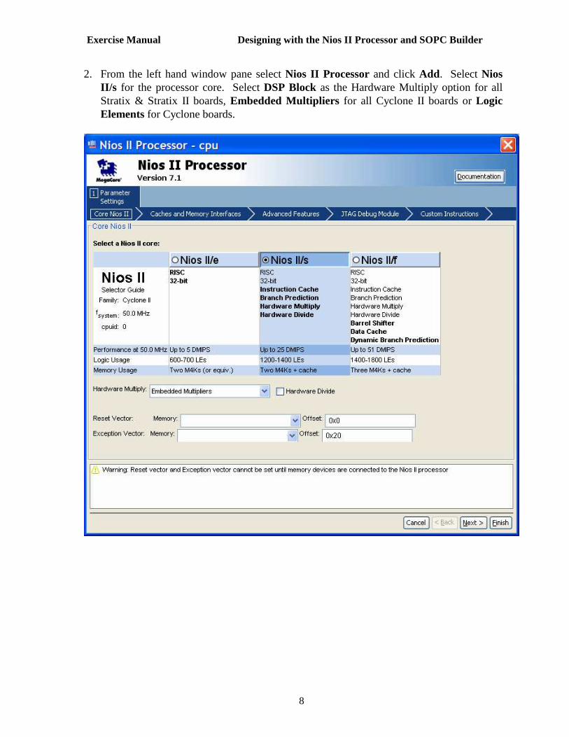
5. In the second page of the wizard, type niosII_training_project as the name of the application to be created. Then verify that the .ptf file from your SOPC Builder session has automatically populated the SOPC Builder System field in the Select Target Hardware pane.
6. Now, select the Blank Project template from the Select Project Template panel on the
left hand side of the window. The New Project window should now resemble the following:

Exercise Manual Designing with the Nios II Processor and SOPC Builder
21
7. Press Next, and select:
Create a new system library named: niosII_training_project_syslib.
Then, click Finish.
8. You have now created two new projects in the Nios II IDE - a Nios II C/C++ Application project and a system library project. However, the Nios II C/C++ Application project is blank and you need to add some source code to it. To add a C file to the project, first expand the niosII_training_project folder in the Nios II IDE. Then Drag a C file into the niosII_training_project folder in the Nios II IDE.

Exercise Manual Designing with the Nios II Processor and SOPC Builder
22
9. Now, highlight the niosII_training_project_syslib folder, right-click, and select Properties.
Then, choose System Library from the left hand side of the Properties window. Ensure that the stdout, stderr and stdin devices are set to jtag_uart and that the System clock timer is set to clk_0.
For all boards except the Cyclone II board, set the Read-only data, Read/write memory, and Program Memory fields to sram.
Please refer to the figure on the next page.
10. Click OK .
11. Compile the program by highlighting the niosII_training_project folder in the Nios II C/C++ Projects window; then right-click and select Build Project.
Note: You can choose to run this command in the background when prompted. This will free up the tool, letting you continue to use it for other tasks; whereas, running it in the foreground causes you wait for it to complete.
12. After the compiler has finished, download and run the program on the development board:
Highlight the niosII_training_project folder then right-click and select
Run As-> Nios II Hardware.

Exercise Manual Designing with the Nios II Processor and SOPC Builder
23
Note 1: If Run terminates before the code downloads to your board, and you get a message pertaining to the JTAG download cable. then select Run > Run… and from the Target Connection tab choose the appropriate download cable that you are using and then press Apply and Run (or see instructor).
Note 2: The Nios II IDE will actually Build the project automatically for you if you
just click Run As -> Nios II Hardware without you having to explicitly go through the Build step. You can enable or disable this option in the Window > Preferences.

Exercise Manual Designing with the Nios II Processor and SOPC Builder
24

Exercise Manual Designing with the Nios II Processor and SOPC Builder
25
13. Now, let’s run the debugger on this design and step through some code. Start the debugger by once again highlighting the niosII_training_project software project folder, then right-clicking on it, and selecting Debug As-> Nios II Hardware. The debugger will launch, connect to the target, and download the program ready for debug.
Choose, Yes to switch perspectives when prompted.
14. Turn on line numbers in the C file editor. To do this, go to the Window menu, and select
Preferences. Open the General folder followed by the Editors sub-folder. Select Text Editor ; then check Show line numbers. Press OK .
15. Set breakpoints on at some line, as you like.
To set a breakpoint, simply place the cursor on the line number or grey area next to it, and double-click. A circle should now appear next to the line number indicating that a breakpoint is set.
16. Click on the resume button .

Exercise Manual Designing with the Nios II Processor and SOPC Builder
26
17. Now, go to the Variables window, and view the contents of the variables.
Watch the variables content while the program is running! Editing the variable values in this way is useful because it gives you a way to emulate external hardware events or other conditions that may otherwise be difficult to replicate!

Exercise Manual Designing with the Nios II Processor and SOPC Builder
27
18. Now terminate and remove the program. Go to the Debug sub-menu menu; right-click on the software project thread, and select Terminate and Remove.
END OF LAB 2

Exercise Manual Designing with the Nios II Processor and SOPC Builder
28
Lab 3: Basic Led & Switches
LEDS:
1. First open a software project (in the IDE), clear all other C files.

Exercise Manual Designing with the Nios II Processor and SOPC Builder
29
2. Include “io.h”. this is all the input-output commands of the cpu. 3. Look for the address of the pio devide in the SOPC builder and compare it to the one in SYSTEM.H.
4. Then use the IOWR_DE2_PIO_DIRECTION(PIO_BASE, DATA) to select direction of the PIO for each bit(!!). 5. Then use the IOWR_DE2_PIO_DATA(PIO_BASE, DATA) to write to PIO. 6. Then use the IORD_DE2_DATA(PIO_BASE) command to read from the PIO. 7. Output ports can connect to different pins then input ports.

Exercise Manual Designing with the Nios II Processor and SOPC Builder
30
Lab 4: Basic LCD
1. First open a software project (in the IDE), clear all other C files. 2. Include the:

Exercise Manual Designing with the Nios II Processor and SOPC Builder
31
• io.h • system.h • altera_up_avalon_character_lcd.h • altera_up_avalon_character_lcd_regs.
3. The LCD address is located in system.h, the name of the address (defined) is the name you had given it in the SOPC. In this case the name is “LCD”, there for the defined address is LCD_BASE : SYSTEM.h
SOPC:
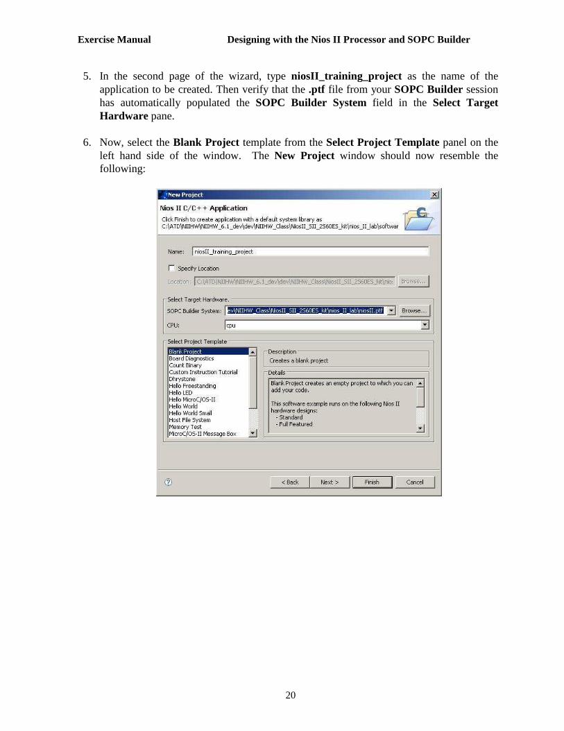
4. All the macro commands which is given to you are located in:
5. altera_up_avalon_character_lcd.h and altera_up_avalon_character_lcd_regs.h are used to
define al the base address off the registers and co nstants to be used later by the macro commands, the can be found here:
Exercise Manual Designing with the Nios II Processor and SOPC Builder
32
LCD initialization commands (order must be kept!):
1. Assign structure: alt_up_character_lcd_open_dev(device_name_as_given_ in_the_SOPC)

Exercise Manual Designing with the Nios II Processor and SOPC Builder
33
How to use? • alt_up_character_lcd_dev *LCD_device;// declare the structure
• LCD_device=alt_up_character_lcd_open_dev( "/dev/lcd" );// assign the new structure to the device.
2. initialize LCD:
OR /AND alt_up_character_lcd_init(alt_up_character_lcd_dev *lcd)
How to use?
• LCD_Init();// just write the program (all of it!) in your code and call it!
• alt_up_character_lcd_init(LCD_device);// use the structure you crated using
“alt_up_character_lcd_open_dev” in this function.
LCD controll commands : *you must add the includes given to you above to the file...!

Exercise Manual Designing with the Nios II Processor and SOPC Builder
34
use alt_up_character_lcd_send_cmd(alt_up_character_lcd_ dev *lcd, alt_u32 cmd) to control the LCD:
1. alt_up_character_lcd_send_cmd(LCD_device, ALT_UP_CH ARACTER_LCD_CTRL_RETURN_HOME);
2. alt_up_character_lcd_send_cmd(LCD_device, ALT_UP_CH ARACTER_LCD_CTRL_DISPLAY_ON);
3. alt_up_character_lcd_send_cmd(LCD_device, ALT_UP_CH ARACTER_LCD_CTRL_CURSOR_ON );
4. alt_up_character_lcd_send_cmd(LCD_device,ALT_UP_CHA RACTER_LCD_CTRL_CURSOR_BLINK_ON);
5. alt_up_character_lcd_send_cmd(LCD_device, ALT_UP_CH ARACTER_LCD_CTRL_DISPLAY_OFF);
6. alt_up_character_lcd_send_cmd(LCD_device,ALT_UP_CHA RACTER_LCD_CTRL_CURSOR_BLINK_OFF);
7. alt_up_character_lcd_send_cmd(LCD_device ,ALT_UP_CH ARACTER_LCD_CTRL_DISPLAY_SHIFT_RIGHT);
8. alt_up_character_lcd_send_cmd(LCD_device, ALT_UP_CH ARACTER_LCD_CTRL_DISPLAY_SHIFT_LEFT);
9. alt_up_character_lcd_send_cmd(LCD_device ,ALT_UP_CH ARACTER_LCD_CTRL_DISPLAY_SHIFT_LEFT);
10. alt_up_character_lcd_send_cmd(LCD_device ,ALT_UP_CH ARACTER_LCD_CTRL_CURSOR_SHIFT_RIGHT);
11. alt_up_character_lcd_send_cmd(LCD_device ,ALT_UP_CH ARACTER_LCD_CTRL_CURSOR_SHIFT_LEFT);
12. alt_up_character_lcd_send_cmd(LCD_device ,ALT_UP_CH ARACTER_LCD_CTRL_DISPLAY_SHIFT_LEFT);
LCD cursor position / write commands:
1. alt_up_character_lcd_write(alt_up_character_lcd_dev *dev, const char *ptr, unsigned int len);
Exercise Manual Designing with the Nios II Processor and SOPC Builder
35
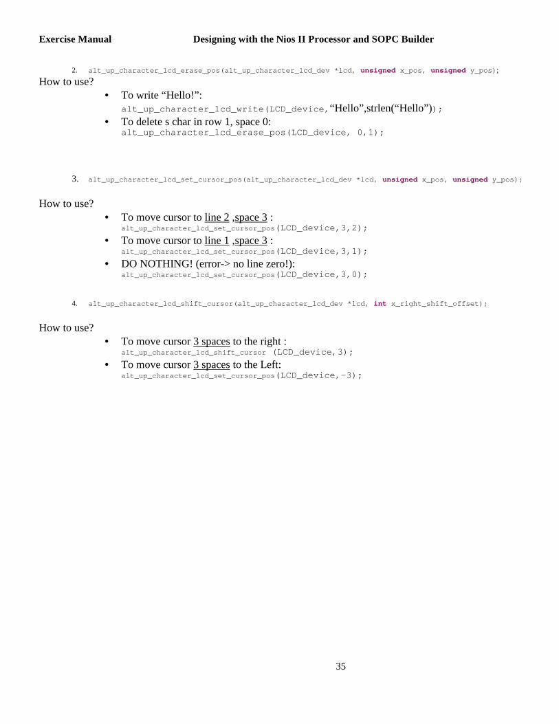
2. alt_up_character_lcd_erase_pos(alt_up_character_lcd _dev *lcd, unsigned x_pos, unsigned y_pos) ;
How to use? • To write “Hello!”:
alt_up_character_lcd_write(LCD_device, “Hello”,strlen(“Hello”));
• To delete s char in row 1, space 0: alt_up_character_lcd_erase_pos(LCD_device, 0,1);
3. alt_up_character_lcd_set_cursor_pos(alt_up_characte r_lcd_dev *lcd, unsigned x_pos, unsigned y_pos);
How to use?
• To move cursor to line 2 ,space 3 : alt_up_character_lcd_set_cursor_pos (LCD_device,3,2);
• To move cursor to line 1 ,space 3 : alt_up_character_lcd_set_cursor_pos (LCD_device,3,1);
• DO NOTHING! (error-> no line zero!): alt_up_character_lcd_set_cursor_pos (LCD_device,3,0);
4. alt_up_character_lcd_shift_cursor(alt_up_character_ lcd_dev *lcd, int x_right_shift_offset);
How to use?
• To move cursor 3 spaces to the right : alt_up_character_lcd_shift_cursor (LCD_device,3);
• To move cursor 3 spaces to the Left: alt_up_character_lcd_set_cursor_pos (LCD_device,-3);

Exercise Manual Designing with the Nios II Processor and SOPC Builder
36

Exercise Manual Designing with the Nios II Processor and SOPC Builder
37
Lab 5: Basic Ps2 - Keyboard
1. First open a software project (in the IDE), clear all other C files. 2. Include the:
• io.h • system.h • altera_up_avalon_ps2.h • altera_up_ps2_keyboard.h • altera_up_avalon_ps2_regs. h

Exercise Manual Designing with the Nios II Processor and SOPC Builder
38
3. The Ps2 address is located in system.h, the name of the address (defined) is the name you had given it in the SOPC. In this case the name is “Ps2”, there for the defined address is Ps2_BASE : SYSTEM.h
SOPC:
4. All the macro commands and “h” files which is given to you are located in:
*We will use only Keyboard... so Mouse can be emitted.
5. altera_up_avalon_ps2.h and altera_up_avalon_ps2_regs. h are used to define al the base address off the registers and constants to be used later by the macro commands be found here:

Exercise Manual Designing with the Nios II Processor and SOPC Builder
39
Ps2 initialization commands (order must be kept!):
1. Assign structure: alt_up_ps2_open_dev(device_name_as_given_in_the_SOP C)
How to use?

Exercise Manual Designing with the Nios II Processor and SOPC Builder
40
• alt_up_ps2_device *ps2;// declare the structure
• alt_up_ps2_device=alt_up_ps2_open_dev( "/dev/ps2" ); // assign the new structure to the device.
• alt_up_ps2_init(ps2);
• alt_up_ps2_clear_fifo(ps2);
2. Ps2 structure can get several values:
1. PS2_KEYBOARD, PS2_KEYBOARD, PS2_UNKNOWN
How to use?
2. Ps2-> device_type==?
KB commands :
Exercise Manual Designing with the Nios II Processor and SOPC Builder
41
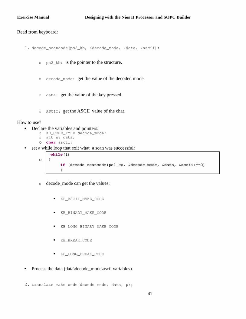
Read from keyboard:
1. decode_scancode(ps2_kb, &decode_mode, &data, &ascii );
o ps2_kb: is the pointer to the structure.
o decode_mode: get the value of the decoded mode.
o data: get the value of the key pressed.
o ASCII: get the ASCII value of the char.
How to use? • Declare the variables and pointers:
o KB_CODE_TYPE decode_mode; o alt_u8 data; o char ascii;
• set a while loop that exit what a scan was successful:
o
o decode_mode can get the values:
� KB_ASCII_MAKE_CODE
� KB_BINARY_MAKE_CODE
� KB_LONG_BINARY_MAKE_CODE
� KB_BREAK_CODE
� KB_LONG_BREAK_CODE
• Process the data (data\decode_mode\ascii variables).
2. translate_make_code(decode_mode, data, p);

Exercise Manual Designing with the Nios II Processor and SOPC Builder
42
How to use? • Declare the variables and pointers:
o char *p; • P will point to a char, represent the pressed key .
o For example: if TAB key is pressed then P will poin t to “TAB” string, and printf(“ %s”, p) will print: “TAB” .
o Table of values given can be seen inside the file “ altera_up_ps2_keyboard.c”:
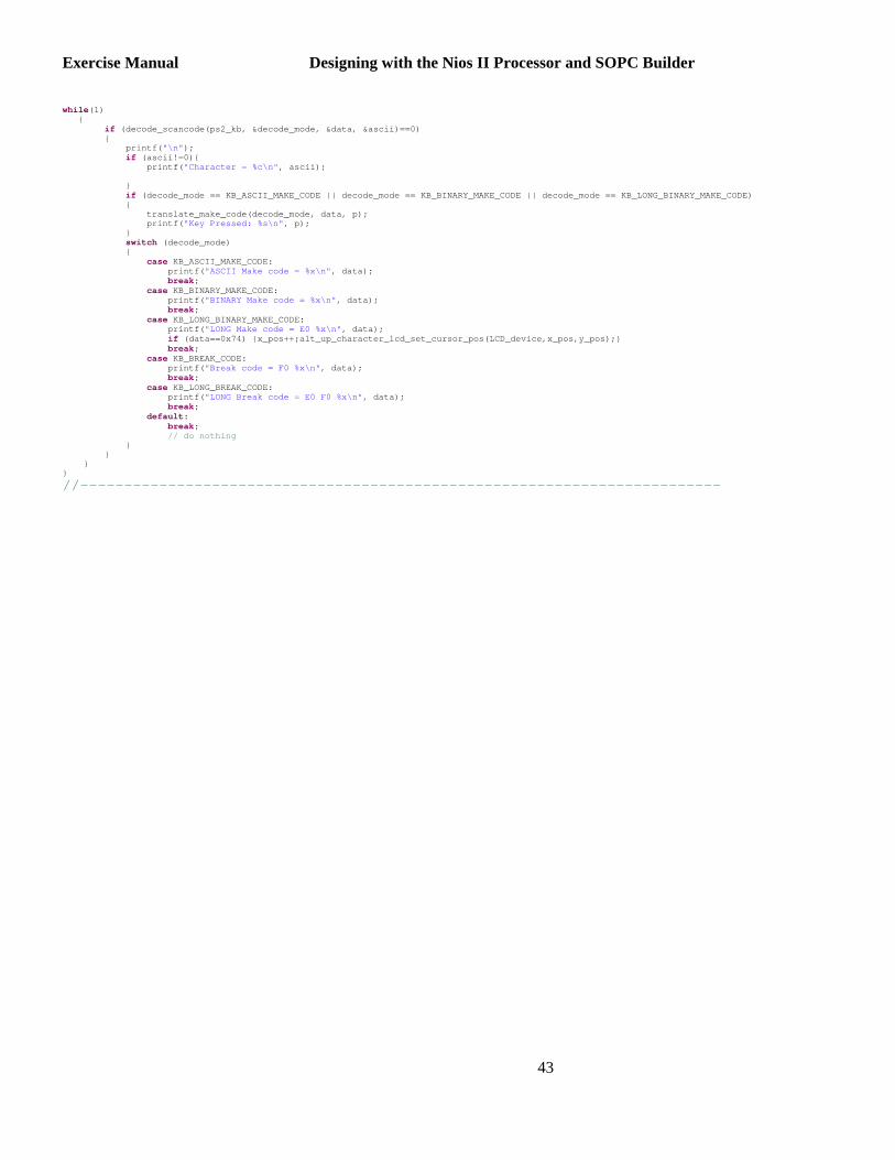
CODE: read from keyboard and display data:
//------------------------------------------------- ------------------------
Exercise Manual Designing with the Nios II Processor and SOPC Builder
43
while (1) { if (decode_scancode(ps2_kb, &decode_mode, &data, &asc ii)==0) { printf( "\n" ); if (ascii!=0){ printf( "Character = %c\n" , ascii); } if (decode_mode == KB_ASCII_MAKE_CODE || decode_mode == KB_BINARY_MAKE_CODE || decode_mode == KB_LONG_BI NARY_MAKE_CODE) { translate_make_code(decode_mode, da ta, p); printf( "Key Pressed: %s\n" , p); } switch (decode_mode) { case KB_ASCII_MAKE_CODE: printf( "ASCII Make code = %x\n" , data); break ; case KB_BINARY_MAKE_CODE: printf( "BINARY Make code = %x\n" , data); break ; case KB_LONG_BINARY_MAKE_CODE: printf( "LONG Make code = E0 %x\n" , data); if (data==0x74) {x_pos++;alt_up_character_lcd_set_cur sor_pos(LCD_device,x_pos,y_pos);} break ; case KB_BREAK_CODE: printf( "Break code = F0 %x\n" , data); break ; case KB_LONG_BREAK_CODE: printf( "LONG Break code = E0 F0 %x\n" , data); break ; default : break ; // do nothing } } } }
//------------------------------------------------- ------------------------

Exercise Manual Designing with the Nios II Processor and SOPC Builder
44
Lab 3
RTL Simulation

Exercise Manual Designing with the Nios II Processor and SOPC Builder
45
In this lab you will use ModelSim-Altera to perform a hardware simulation of the processor running code out of SRAM memory. 1. Copy your project to another folder by using the build in “copy project” command. 2. Remove all bridges to non SOPC systems. 3. Replace memory to be on-chip memory. 4. In SOPC Builder, the simulation model of the JTAG UART’s can be configured to generate a data stream to
send to the host processor.
To set this up, return to the SOPC Builder System Contents page, and double click on the jtag_uart peripheral in order to re-open it. When the dialog box opens, click on the Simulation tab. Select the Create ModelSim alias to open an interactive stimulus/response radio button, and then hit Finish
Exercise Manual Designing with the Nios II Processor and SOPC Builder
46
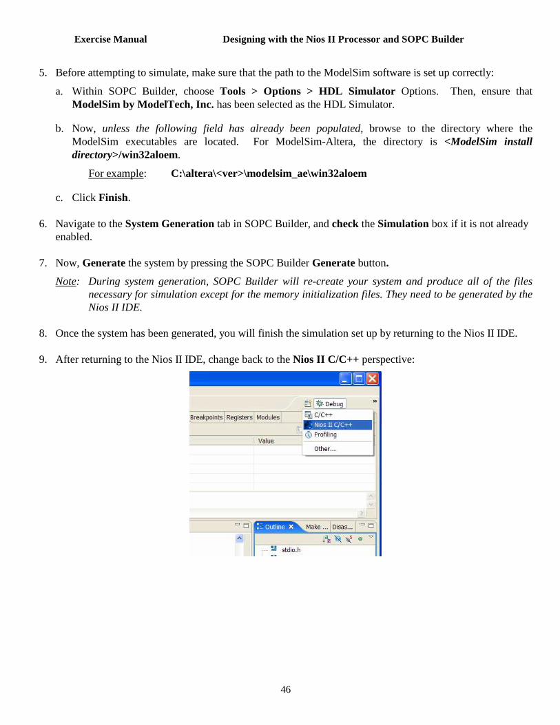
5. Before attempting to simulate, make sure that the path to the ModelSim software is set up correctly:
a. Within SOPC Builder, choose Tools > Options > HDL Simulator Options. Then, ensure that ModelSim by ModelTech, Inc. has been selected as the HDL Simulator.
b. Now, unless the following field has already been populated, browse to the directory where the ModelSim executables are located. For ModelSim-Altera, the directory is <ModelSim install directory>/win32aloem.
For example: C:\altera\<ver>\modelsim_ae\win32aloem
c. Click Finish. 6. Navigate to the System Generation tab in SOPC Builder, and check the Simulation box if it is not already
enabled. 7. Now, Generate the system by pressing the SOPC Builder Generate button.
Note: During system generation, SOPC Builder will re-create your system and produce all of the files necessary for simulation except for the memory initialization files. They need to be generated by the Nios II IDE.
8. Once the system has been generated, you will finish the simulation set up by returning to the Nios II IDE. 9. After returning to the Nios II IDE, change back to the Nios II C/C++ perspective:

Exercise Manual Designing with the Nios II Processor and SOPC Builder
47
10. Then, modify the system library parameters for your software project. You will need to specify which
memory you wish to compile code into and whether you want enhance the simulation of your system by reducing code overhead. To do this, right click on the system library project, and select Properties.
11. Next, from the Properties page, select System Library. Recall that this page controls which
communication devices in your design should be used for standard input / output and also which memories your code gets assigned to.
o Select on_chip_memory. and keep jtag_uart as stdout, stderr and stdin.
o Enable the ModelSim only, no hardware support simulation feature.
o Check “reduce device drivers” and “reduce C library”.
o Click OK
Note: Checking the ModelSim only, no hardware support checkbox tells the compiler that the current project is being run on a simulator. The compiler will, in turn, remove sections of the start-up code to improve simulation speed. Note that the resulting software image will not run on a target board.

Exercise Manual Designing with the Nios II Processor and SOPC Builder
48
12. In the Nios II C/C++ Projects panel of the Nios II IDE, re-build by highlighting and right-clicking on it, then selecting Build Project.
13. Once build completes, use the Nios II IDE to launch ModelSim. Again, highlight the project, but this time
select Run As > Nios II ModelSim. -------------------------------------------------------------------------------------------------------------- 14. This should open the ModelSim project generated by SOPC Builder.
Note: If you encounter an error in this step, however, and the project does not open properly, then your will simply need to manually open the Modelsim project (niosII_sim.mpf) manually and execute the set-up script (setup_sim.do), yourself.
To do this, select File > Open in ModelSim, and then browse to the niosII_sim folder where your project file is located. Once inside this directory, select niosII_sim.mpf, and press Open. (Note: You will need to set Files of type to Project Files (*.mpf) in order to see this file.)
Then, type source setup_sim.do at the ModelSim TCL prompt. -------------------------------------------------------------------------------------------------------------- 15. You are now in a position to easily compile and simulate your Nios II design in ModelSim with the help of
some macros that are generated by the Altera setup script. You can execute all of these macros at the ModelSim command line.

Exercise Manual Designing with the Nios II Processor and SOPC Builder
49
16. Some of their descriptions are listed in the following table:
Nios II Simulation Macros Macro
s
Recompiles the Nios II processor and peripheral source code and then reloads the design into the ModelSim work library for simulation. This macro resets the entire simulation.
c This is a legacy command that is not supported for designs generated using the Nios II IDE. It’s purpose was to recompile source code and reinitialize the system memories. For Nios II the recommended approach to reinitializing memories is to recompile your design in Nios II IDE and then restart your design in ModelSim after the Nios II IDE compilation is complete.
w Loads the wave_presets.do file, which contains predefined ModelSim waveform window information. The wave_presets.do file loads the common signals from all of the processors and peripherals that reside on-chip and displays the ModelSim waveform window.
l Sets up the ModelSim List window with predefined signals for viewing simulation results in a list format. The list format is text-based instead of graphical.
<UART name>_drive Optional. For each UART or JTAG_UART in the system, this macro is created if you turned on the interactive/stimulus response window inside the SOPC Builder before system generation. When you run this macro it opens a window, similar to a terminal screen, where you can send virtual data to the UART RXD signal during simulation.
<UART name>_log Optional. For each UART or JTAG_UART in the system, this macro is created if you turned on the option “window to show output as ASCII text” before you generate your system generation. This macro opens a window, similar to a log window, where you can monitor printf’s while simulating.
h Help. Displays the available macros and their functions.

Exercise Manual Designing with the Nios II Processor and SOPC Builder
50
17. The first step in simulating the Nios II design is to load it into ModelSim by typing “s” at the console prompt located in the ModelSim Transcript window. This will compile all of the relevant HDL design files into ModelSim.
18. Next, type “jtag_uart_drive” to launch the interactive terminal window. This console will display the
output of the printf statement in the simple.c source code. (If ModelSim does not recognize this macro, then use “jtag_uart_log” instead as you probably forgot to set the jtag_uart’s simulation model to an interactive stimulus/response window earlier in the lab.)
19. Type “w” at the ModelSim command prompt to execute a macro that opens the ModelSim waveform
window and pre-populate it with a number of example signals from your system. These signals are delineated by function in the waveform viewer and were chosen because they are particularly useful specifically for debugging.
20. In the Objects window, select chipselect and out_port. Drag them into the waveform window, placing
them at the bottom of the list of signals. (Note: Hold down Ctrl in order to grab multiple individual objects.)

21. In the Wave window, right click on out_port and select Insert Divider . This will insert a dividing line directly above the signals you just added. Rename the “New Divider” to Extra Signals by right-clicking on it, selecting properties, and then typing the new name.
22. Run the simulation for 300 us by typing run 300 us at the ModelSim console prompt in
the Transcript window.
23. After the simulation has completed, the terminal window should display the printf
statements from the C file.
24. From the File menu in ModelSim, select Quit to exit. 25. Also, close the jtag_uart console window.

Exercise Manual Designing with the Nios II Processor and SOPC Builder
52
Lab 5: Adding Pll to Nios II Processor System

Exercise Manual Designing with the Nios II Processor and SOPC Builder
53
1. Add the Altera PLL component to the project from the PLL folder. Then launch the ALTPLL MegaWizard and configure the PLL using the settings shown below. (Note: You navigate through the Wizard using the Next button.)
Ex for phase and freq diveding \ multiplaying:
Input Clock Freq 50 MHz Auto PLL Selection ON Mode Normal
Output Tap Settings: C0: Mult Factor = 17 Div factor = 10 Phase shift (ns) 0 Duty Cycle = 50%
C1: Mult Factor = 17 Div factor = 10 Phase shift (ns) -4.80 Duty Cycle = 50%
Note: to enable PLL output tap C1, check the “Use this clock” check box

Exercise Manual Designing with the Nios II Processor and SOPC Builder
54
2. After you configure the PLL to match the setting shown above, the final page of the PLL Wizard should resemble the following: (Note: there will be some minor differences depending on what language you have chosen or development kit you are using for your project.)
Select Finish again and then Finish one more time to add the component to the SOPC Builder system; then re-name it, pll .

Exercise Manual Designing with the Nios II Processor and SOPC Builder
55
3. Double click on “pll_c0”in the Name column in the Clock Settings window in the top right corner of the SOPC Builder tool, and type over the text to re-name it as you wish... (we re-named pll_c1 to ssram_clk) The system Clock window should appear as follows:
Cyclone II and Stratix II rohs Nios II Development Kits: