Embed Size (px)
Citation preview

Designing a Smart Grid Communication System to Achieve 99.999% Link Availability
White Paper
AbstractTo upgrade today’s mature electrical infrastructure
for the Smart Grid, utilities are investing in initiatives such as automatic restoration, Volt-Var optimization, and advanced SCADA. High-reliability, high-capacity communication systems are needed to handle the requirements of the switching and protection devices associated with these initiatives.
This paper discusses the issues to consider in implementing a communication system that can provide the “five nines” availability needed for such Smart Grid applications—equivalent to 5.26 minutes of the downtime annually. It considers point-to-point, point-to-multipoint, and mesh communication systems. And it explains why mesh communication systems provide the best overall performance for Smart Grid applications.
Changing Control and Communication NeedsAs today’s electrical infrastructure transitions to the
Smart Grid, grid functions are moving from centralized control to peer-to-peer control, which can perform the necessary decision-making more quickly and efficiently. There’s an ever-increasing need for real-time distribution system data, and thus the high-
availability, high-capacity mesh communication systems that can provide this data.
But what does “high availability” mean? To the uninitiated, it might seem that 99% or 99.9% availability would satisfy the communication system performance needs of the Smart Grid.
It doesn’t.
Let’s take a closer look to the implications of a few “nines” on availability.
Understanding AvailabilityAs shown in the table below, a communication
system offering 99% (two nines) availability means that it isn’t available 3.65 days per year. By most utility customers’ standards, such availability is not acceptable.
Industries such as oil and gas have availability requirements similar to electric utilities and typically utilize communication systems designed for a minimum of three nines availability for low-priority traffic and five nines availability for critical traffic.
Not many kinds of communication systems offer the high level of availability—plus the bandwidth and low latency—required for Smart Grid applications.
Availability, % Downtime per Year Downtime per Month Downtime per Week
99.9999% (“six nines”) 31.5 seconds 2.59 seconds 0.605 seconds
99.999% (“five nines”) 5.26 minutes 25.9 seconds 6.05 seconds
99.99% (“four nines”) 52.56 minutes 4.32 minutes 1.01 minutes
99.95% 4.38 hours 21.56 minutes 5.04 minutes
99.9% (“three nines”) 8.76 hours 43.2 minutes 10.1 minutes
99.8% 17.52 hours 86.23 minutes 20.16 minutes
99.5% 1.83 days 3.60 hours 50.4 minutes
99% (“two nines”) 3.65 days 7.20 hours 1.68 hours
90% (“one nines”) 36.5 days 72 hours 16.8 hours
2 Designing a Smart Grid Communication System to Achieve 99.999% Link Availability
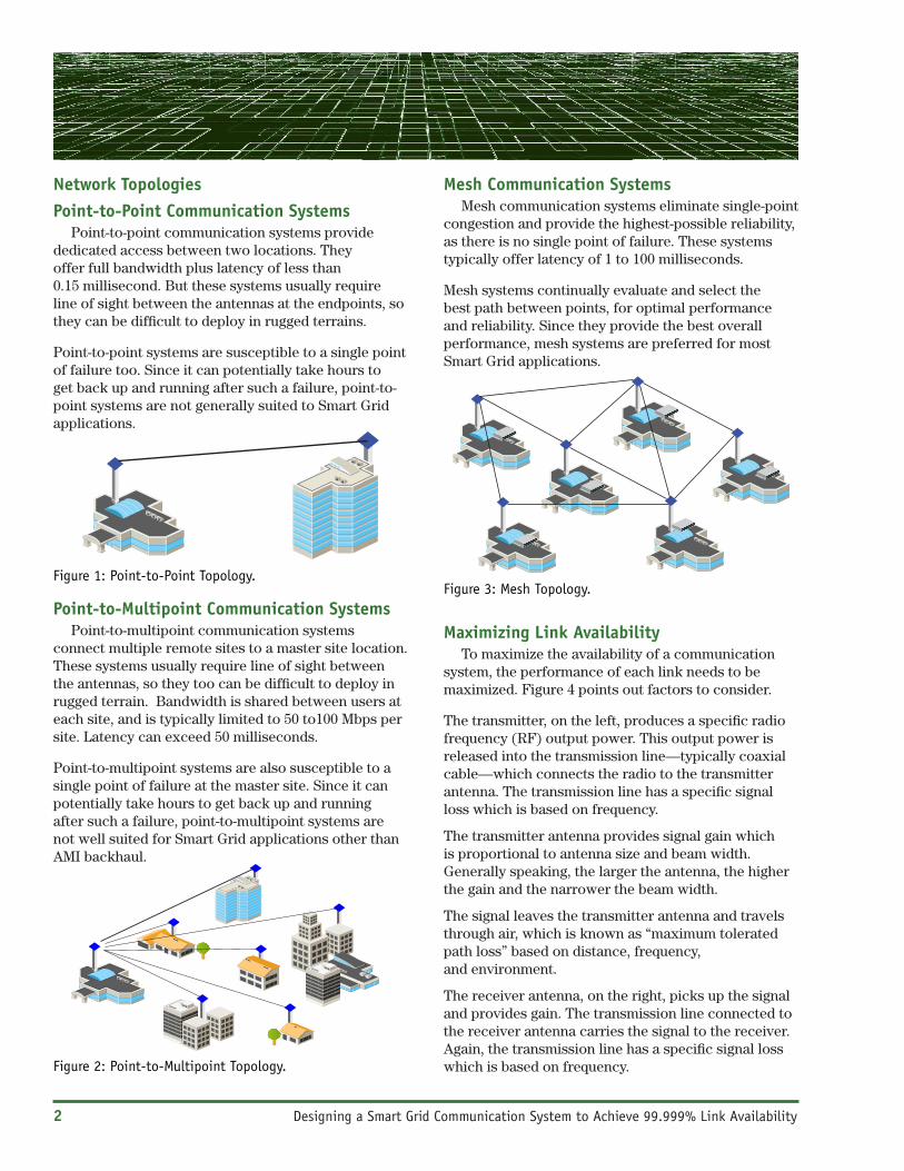
Network Topologies Point-to-Point Communication Systems
Point-to-point communication systems provide dedicated access between two locations. They offer full bandwidth plus latency of less than 0.15 millisecond. But these systems usually require line of sight between the antennas at the endpoints, so they can be difficult to deploy in rugged terrains.
Point-to-point systems are susceptible to a single point of failure too. Since it can potentially take hours to get back up and running after such a failure, point-to-point systems are not generally suited to Smart Grid applications.
Point-to-Multipoint Communication SystemsPoint-to-multipoint communication systems
connect multiple remote sites to a master site location. These systems usually require line of sight between the antennas, so they too can be difficult to deploy in rugged terrain. Bandwidth is shared between users at each site, and is typically limited to 50 to100 Mbps per site. Latency can exceed 50 milliseconds.
Point-to-multipoint systems are also susceptible to a single point of failure at the master site. Since it can potentially take hours to get back up and running after such a failure, point-to-multipoint systems are not well suited for Smart Grid applications other than AMI backhaul.
Mesh Communication SystemsMesh communication systems eliminate single-point
congestion and provide the highest-possible reliability, as there is no single point of failure. These systems typically offer latency of 1 to 100 milliseconds.
Mesh systems continually evaluate and select the best path between points, for optimal performance and reliability. Since they provide the best overall performance, mesh systems are preferred for most Smart Grid applications.
Maximizing Link AvailabilityTo maximize the availability of a communication
system, the performance of each link needs to be maximized. Figure 4 points out factors to consider.
The transmitter, on the left, produces a specific radio frequency (RF) output power. This output power is released into the transmission line—typically coaxial cable—which connects the radio to the transmitter antenna. The transmission line has a specific signal loss which is based on frequency.
The transmitter antenna provides signal gain which is proportional to antenna size and beam width. Generally speaking, the larger the antenna, the higher the gain and the narrower the beam width.
The signal leaves the transmitter antenna and travels through air, which is known as “maximum tolerated path loss” based on distance, frequency, and environment.
The receiver antenna, on the right, picks up the signal and provides gain. The transmission line connected to the receiver antenna carries the signal to the receiver. Again, the transmission line has a specific signal loss which is based on frequency.
Figure 1: Point-to-Point Topology.
Figure 2: Point-to-Multipoint Topology.
Figure 3: Mesh Topology.

Designing a Smart Grid Communication System to Achieve 99.999% Link Availability 3
The receiver requires a minimum signal strength to maintain error-free communication. This parameter is called the “radio receiver threshold.” In designing a communication system, the actual receive signal strength should be 20 to 40 dB above this threshold.
Best practice dictates that antennas with the narrowest-practical beam be used, to minimize interference and maximize signal gain . . . and thus achieve the highest-possible link availability.
Designing a Communication SystemTo design the communication system, you’ll need to
add up the bandwidth requirements of all existing and proposed switching and protection device radios. This ensures that the design will have sufficient capacity.
Then obtain the GPS coordinates for all communicat-ing device sites, and enter them in Google Earth™ mapping service, as shown in Figure 5 below.
Figure 4: Link Path Factors.
Figure 5: Picking GPS Coordinates.
Radio(Output Power)
Transmission Line (Loss)
Antenna (Gain)
MaximumToleratedPath Loss
Radio(Threshold)
Antenna (Gain)
Transmission Line (Loss)

Prin
ted
in U
.S.A
.
April 8, 2013 © sandc.com • twitter.com@SandC_US • twitter.com@SandC_UK 1070-T103
SummaryFollow this checklist to achieve the highest level
of availability—plus the bandwidth and low latency—required for your Smart Grid communication system:
• Engineer every link in the system to the desired throughput and availability.
• Verify design specifications are met in actual deployment.
• Monitor performance regularly and perform maintenance as needed to maintain expected performance.
Wireless engineering is a science. Follow good practices, make accurate measurements, and your communication system will perform with high availability for many years.
Copy the site information into the path planning tool. Select the appropriate frequency band, product, antennas, and various adjustable parameters so the design meets your requirements. Figure 6 shows the final performance model.
Data collected from a field survey can be used to update the model in the planning tool so a final design can be created. Please refer to Figure 7.
Once the communication system is installed, a field acceptance test should be performed to ensure that each link in the system is performing to the design specifications.
Figure 6: Link Performance Model.
Figure 7: Google Earth Final Link Design.


![[Smart Grid Market Research] India: Smart Grid Legacy, Zpryme Smart Grid Insights, September 2011](https://img.dokumen.tips/doc/110x75/541402518d7f7294698b47d4/smart-grid-market-research-india-smart-grid-legacy-zpryme-smart-grid-insights-september-2011.jpg)

![[Smart Grid Market Research] South Korea: Smart Grid Revolution, Zpryme Smart Grid Insights, July 2011](https://img.dokumen.tips/doc/110x75/5414026d8d7f727d698b47c7/smart-grid-market-research-south-korea-smart-grid-revolution-zpryme-smart-grid-insights-july-2011.jpg)


![[Smart Grid Market Research] Smart Grid Index: November 2012 - Zpryme Smart Grid Insights](https://img.dokumen.tips/doc/110x75/541402018d7f728a698b47a5/smart-grid-market-research-smart-grid-index-november-2012-zpryme-smart-grid-insights.jpg)