Embed Size (px)
Citation preview

Design Requirements and Engineering Considerations 1
D:\TEACH\THAI-TM2\text\CHAP2.doc 2001-03-14
Design Requirements and Engineering Considerationsprepared by
Wm. J. Garland, Professor, Department of Engineering Physics,McMaster University, Hamilton, Ontario, Canada, March 2001, Revision 1.0
[Based on reference BRO72]
More about this documentSummary:
The basic requirements of fuel, moderator and coolant dictate key design decisions which definethe various reactor types.
Table of Contents
1 Introduction............................................................................................................................. 32 Basic Neutron Cycle ............................................................................................................... 43 Possible Fuels.......................................................................................................................... 54 Heat Transfer Considerations.................................................................................................. 65 Uranium Fuel Forms ............................................................................................................... 76 Fuel Claddings ...................................................................................................................... 107 Reactor Coolants................................................................................................................... 128 Neutron Moderators .............................................................................................................. 159 Moderating Arrangements .................................................................................................... 1710 HTS Design Requirements and Engineering Considerations ............................................... 1911 Power Reactor Types ............................................................................................................ 22
11.1 "Magnox" Reactors ....................................................................................................... 2211.2 AGR .............................................................................................................................. 2311.3 HTGCR......................................................................................................................... 2311.4 PWR.............................................................................................................................. 2411.5 BWR ............................................................................................................................. 2511.6 LMFBR ......................................................................................................................... 2511.7 CANDU ........................................................................................................................ 27
11.7.1 Neutron Economy ..................................................................................................... 2711.7.2 Pressure Tubes .......................................................................................................... 2711.7.3 On-Power Fuelling.................................................................................................... 2811.7.4 Separate Moderator ................................................................................................... 28
11.8 CANDU-PHW .............................................................................................................. 2811.9 CANDU-BLW .............................................................................................................. 3111.10 CANDU-OCR............................................................................................................... 3111.11 A Comparison Between CANDU Reactors and Other Types....................................... 33
List of Figures

Design Requirements and Engineering Considerations 2
D:\TEACH\THAI-TM2\text\CHAP2.doc 2001-03-14
Figure 1 Basic power reactor schematic arrangement .................................................................... 3Figure 2 The basic neutron cycle .................................................................................................... 4Figure 3 Tradeoff between heat transfer and neutron capture ........................................................ 6Figure 4 Basic reactor fuel arrangement ......................................................................................... 7Figure 5 Moderating arrangements ............................................................................................... 18Figure 6 Schematic arrangement - Gas Cooled Reactors.............................................................. 22Figure 7 Schematic arrangement - PWR....................................................................................... 24Figure 8 Schematic arrangement - BWR ...................................................................................... 25Figure 9 Schematic arrangement - LMFBR.................................................................................. 26Figure 10 CANDU PWR schematic ............................................................................................. 30Figure 11 Simplified station flow diagram - CANDU BWR........................................................ 32
List of Tables
Table 1 Forms of uranium in power reactor fuel ............................................................................ 8Table 2 Desirable fuel material properties ...................................................................................... 8Table 3 Uranium fuel form summary.............................................................................................. 9Table 4 Alternative fuel cladding materials .................................................................................. 10Table 5 Desirable cladding properties .......................................................................................... 10Table 6 Fuel cladding summary.................................................................................................... 11Table 7 Alternatuve power reactor coolants ................................................................................. 12Table 8 Desirable features of reactor coolants............................................................................. 12Table 9 Coolant summary............................................................................................................. 14Table 10 Slowing down parameters of typical moderators [Source: DUD76, table 8-1] ............. 15Table 11 Desirable features of moderators ................................................................................... 15Table 12 Alternative power reactor moderators............................................................................ 16Table 13 Moderator summary....................................................................................................... 16

Design Requirements and Engineering Considerations 3
D:\TEACH\THAI-TM2\text\CHAP2.doc 2001-03-14
1 Introduction
All presently developed nuclear power reactors act as sources of thermal energy, producing electricitythrough the conventional "heat engine" process. This is shown diagrammatically in Figure 1. In all currentcentral generating station applications, steam is the final working fluid with more or less conventionalsteam turbines being employed to drive the electrical generators.
The thermal energy is generated within the nuclear fuel which resides within the nuclear reactor. Thisthermal energy is transferred from the fuel by a fluid medium called the reactor coolant. This fluidmedium may be boiling water, in which case the steam may be used directly in the turbine (the reactor isthen called a direct cycle reactor) or it may act as an intermediate heat transport medium, giving up its heatto raise steam in external heat exchangers called boilers or steam generators (the reactor is then calledan.indirect cycle reactor).
The various types of power reactors in use today differ regarding the nuclear fuel and the reactor coolantsused and also in one further important regard, the type of medium used to slow down or moderate the highenergy neutrons produced by the fission process.
Figure 1 Basic power reactor schematic arrangementWe first look at the life cycle of neutrons in the typical nuclear reactor and then consider the variousalternative nuclear fuels, coolants, and moderators in current use in commercial power reactors.

Design Requirements and Engineering Considerations 4
D:\TEACH\THAI-TM2\text\CHAP2.doc 2001-03-14
2 Basic Neutron Cycle
Figure 2 depicts the basic neutron cycle wherein a slow neutron is absorbed by a fissile nucleus, causingfission and the emitting of 2 or 3 fast neutrons. The probability of these fast neutrons interacting withother fissile nuclei is low relative to the probability of fission with slow neutrons; hence, the fissionneutrons must be slowed down or moderated. This is done by collision with the surrounding media. During the course of this interaction, some neutrons are lost by absorption that do not lead to fission(parasitic absorption).
If one thermal (slow) neutron ultimately leads to at least one thermal neutron in the next generation, then achain reaction is achieved. For this to be the case, the process must exhibit an "economy of neutrons". Weneed to:
• enhance the probability of neutron moderation• reduce the probability of neutron absorption• enhance the probability of fissioning.
This occurs subject to the following constraints:• safety: the reaction needs to be controllable• cost: overall cost should be minimized• process: the reactor system must perform the desired function (ie, generate X MWe)
given the limitations such as heat sink capacity, etc
Figure 2 The basic neutron cycle

Design Requirements and Engineering Considerations 5
D:\TEACH\THAI-TM2\text\CHAP2.doc 2001-03-14
3 Possible Fuels
The probability of neutron capture leading to fission (called the fission cross section) is larger for slowneutrons than for fast neutrons. Hence, most practical reactors are "thermal" reactors, that is, they utilizethe higher thermal cross sections. Possible fuels include 233U (a fissile material that can be formed from232Th by neutron bombardment) and 239Pu (also fissile and produced from 238U by neutron bombardment). With one notable exception, all other fissile fuels require a high energy neutron to fission and the crosssection is low. The only naturally occurring fuel of significant quantities is 235U, hence most reactors usethis fuel.
Naturally occurring uranium is composed of 0.7% 235U. The rest is 238U. This percentage is too low tosustain a chain reaction when combined with most practical moderators. Hence, to achieve criticality,either, the probability of fission must be enhanced or the moderator effectiveness must be enhanced. Onegroup of reactor types (PWR, BWR, HTGR) enrich the fuel (a costly task) and use a cheap moderator(ordinary water or graphite). Alternatively, natural uranium (relatively cheap) is used with an excellent butexpensive moderator (heavy water). This is the CANDU approach. In a later section, we shall see whyheavy water is such a good moderator.
Enriching the fuel leads to a reactor system with a lower capital cost but higher operating cost than usingnatural uranium and heavy water. The overall cost over the life if the plant is about the same for eithercase.
Fast fissions do occur with 238U and can contribute up to 3% to the fission process. But more importantly,some of the 238U is converted to 239Pu which subsequently fissions. In CANDU reactors and other reactorsfuelled by natural uranium, roughly 50% of the power is generated through 238U. This is less true forreactors with enriched fuel simply because there is relatively less 238U present in the fuel.

Design Requirements and Engineering Considerations 6
D:\TEACH\THAI-TM2\text\CHAP2.doc 2001-03-14
4 Heat Transfer ConsiderationsAll other things being equal, heat transfer is proportional to surface area. Therefore, best geometries forfuel are those with high area / volume ratios, such as flat plates. However, because a finite thickness ofsheath is required, this is not optimum for low parasitic absorption. This is illustrated in figure 3.
Figure 3 Tradeoff between heat transfer and neutron capture
In addition, to cope with internal pressure generated by fission product gases and swelling at highpowers, the circular geometry is better. Tubes are also more economical to manufacture.
Given that many geometries can be made to operate practically and safely, the choice boils down to one ofcost.
Low sheath low absorption lossesLow area / volume poor heat transfer
∑ →→
High sheath high absorption lossesHigh area / volume good heat transfer
∑ →→
Pin type fuel Plate type fuel

Design Requirements and Engineering Considerations 7
D:\TEACH\THAI-TM2\text\CHAP2.doc 2001-03-14
5 Uranium Fuel Forms
In discussing fuel, coolants and moderators, you will note that neutron economy is repeatedly mentioned asan important parameter. This is true even for enriched uranium reactors because the amount ofenrichment, and hence the cost of the fuel, is very sensitive to the neutron economy of the reactor. This isparticularly so because the enriching of uranium is very costly since it involves an isotope separationprocess rather than a chemical separation process. No matter which process is chosen, it must utilize thevery slight difference in physical properties between the U-238 and U-235 atoms; hence, the process isinherently costly.
In all commercial power reactors, the fuel is used in solid form. Various geometries are employed such assolid rods, plates, spheres, or annular rings. Solid round rods (see Figure 4) are used predominantly,primarily because of manufacturing costs. A basic parameter governing fuel design is the external surfacearea to volume ratio. Good heat transfer to the coolant medium is promoted by high values of this ratiowhereas low fuel manufacturing costs and, generally, good neutron economy are promoted by low valuesof this ratio. This presents a "classical" problem in optimization during the reactor design process, asdiscussed previously.
In certain power reactors, the fuel material is in the form of uranium metal. Other forms are alsoused as listed in table 1. Before discussing the merits of the alternative forms, it is useful toconsider the desirable properties of fuel material. These are listed in table 2.
Figure 4 Basic reactor fuel arrangement

Design Requirements and Engineering Considerations 8
D:\TEACH\THAI-TM2\text\CHAP2.doc 2001-03-14
Table 1 Forms of uranium in power reactor fuel1. URANIUM METAL2. URANIUM/OTHER METAL. ALLOY3. CERAMIC URANIUM DIOXIDE4. URANIUM CARBIDE5. URANIUM SILICIDE
Table 2 Desirable fuel material properties1. LOW COST - CONSTITUENTS AND FABRICATION2. GOOD NEUTRON ECONOMY3. GOOD CORROSION RESISTANCE TO COOLANT4. PHYSICAL STABILITY UNDER EFFECTS OF IRRADIATION, TEMPERATURE,
PRESSURE
Uranium metal is generally lowest in manufacturing cost and highest in neutron economy, the latterbecause of its high density and the absence of the other neutron absorbing elements. On the debit side ofthe ledger, it has poor corrosion resistance to most coolants which is of importance in the event of fuelcladding (to be discussed later) failures. Its geometric stability in reactor use is poor, primarily because ofthe swelling effects of fission products whose specific volume is, of course, greater than the parenturanium. Small quantities of alloying agents have been found useful but do not fully solve the problem. The problem is aggravated by a metallurgical phase change at relatively moderate temperatures whichcauses further geometric distortion. This limits the operating power density achievable with the fuel.
Larger quantities of alloying agents such as zirconium can be used which effectively cure the geometricstability problem and the coolant corrosion problem. Unfortunately both the cost and neutron economysuffer. This fuel is used for certain specialized applications where the latter factors are not of overridingimportance. Uranium - aluminum alloys are attractive for low power density, pressure and temperaturesituations such as research reactors.
Uranium dioxide is the form in which the uranium fuel is used in the vast majority of today's powerreactors. It is somewhat more expensive to manufacture and less neutron economical than uranium metalbecause of its lower density but possesses excellent corrosion resistance to most coolants and a high degreeof geometric stability. Being a ceramic, it is capable of high operating temperatures.
Uranium carbide is attractive as a future fuel for certain types of reactors. It is relatively inexpensive tomanufacture (comparable to UO2) and has somewhat better neutron economy than UO2 (because of itshigher density, but not as good as uranium metal. It has good corrosion resistance to many coolants butunfortunately not to water. Its dimensional stability is good and it can operate at high temperatures.
Uranium silicide is a more recent development having most of the advantages of uranium carbide and, inaddition, adequate resistance to corrosion by water coolants.
The above properties of the various uranium fuel forms are summarized in the following table:

Design Requirements and Engineering Considerations 9
D:\TEACH\THAI-TM2\text\CHAP2.doc 2001-03-14
Table 3 Uranium fuel form summaryU Fuel Form Cost Neutron
EconomyCorrosion Physical Stability
U Metal Lowest (dense +no parasites)
OK Poor Poor (swells due toFP), limits powerdensity
U Alloy Higher Lower OK OKUO2 Higher Lower Excellent Excellent, high T
possibleUC Lower than UO2 UO2<UC<U Metal Good except
against waterGood, high Tpossible
US ~ UC ~ UC Good even withwater
~ UC

Design Requirements and Engineering Considerations 10
D:\TEACH\THAI-TM2\text\CHAP2.doc 2001-03-14
6 Fuel Claddings
In the fission process, new isotopes of a wide variety of elements are produced. These are called fissionproducts. Many of these remain radioactive for significant durations of time after they are generated and,hence, constitute a potential radiation hazard to plant operators and the public at large. It is thereforeclearly desirable to keep these fission products "bottled up" within the fuel where they are generated.
This is the primary function of the fuel cladding. This cladding takes the form of an impervious "skin" or"shell" which encloses the fuel material proper. Most cladding materials in current use are metals althoughceramic-type materials have had limited use in certain applications. Table 3 lists the commonly usedpower reactor cladding materials. Before discussing the merits and demerits of each it is useful to considerthe desirable properties of cladding materials. These are summarized in table 4.
Table 4 Alternative fuel cladding materials1. ALUMINUM2. MAGNESIUM (MAGNOX)3. STAINLESSSTEEL4. ZIRCONIUM5. CERAMICS
Table 5 Desirable cladding properties1. CORROSION RESISTANCE TO COOLANT2. MECHAN ICAL DURABILITY3. HIGH OPERATING TEMPERATURE CAPABILITY4. GOOD NEUTRON ECONOMY5. LOW COST - BASE MATERIAL & FABRICATION6. IMPERMEABILITY TO FISSION PRODUCTS
Aluminum and its alloys possess many attractive properties such as low cost, easy fabrication,high ductility (important in preventing cladding failures), good neutron economy, andimpermeability to fission products. Their major disadvantages for power reactor use are poormechanical properties at high temperatures and poor high temperature corrosion resistance withmost coolants. Since the latter are temperature dependent, aluminum alloys are widely used inresearch reactor fuels where cladding operating temperatures are low but are not currently used inpower reactors.
Magnesium alloys are similar to aluminum alloys in most regards. An alloy called "Magnox"has, however, better high temperature properties and adequate corrosion resistance to permit itsuse in some CO2 cooled power reactors.

Design Requirements and Engineering Considerations 11
D:\TEACH\THAI-TM2\text\CHAP2.doc 2001-03-14
Stainless steel is a very attractive material in all major regards except for its poor neutroneconomy. It has been and still is used in a number of enriched uranium reactors where its poorneutron economy is somewhat less important.
Zirconium, in various low-alloy forms, is by far the most common cladding material in current use. Despite its relatively high base material cost, it combines to a large degree all of the other desirablecladding properties for use with most coolants.
The use of ceramics and ceramic-type materials have potential for very high temperature applications. Their primary disadvantage is, of course, a lack of ductility which makes them liable to brittle fracture.
The above properties of the various fuel cladding are summarized in the following table:
Table 6 Fuel cladding summaryCladdingType
CorrosionResistance
MechanicalDurability
High TCapability
NeutronEconomy
Cost FPContainment
Al Good exceptat high T
Low Low Good Low Good
Mg ~Al, OK forCO2
~ Al > Al ~ Al > Al ~ Al
StainlessSteel
Good Good Good Poor Good Good
Zr OK OK OK Excellent High GoodCeramic Good Brittle Excellent OK OK OK

Design Requirements and Engineering Considerations 12
D:\TEACH\THAI-TM2\text\CHAP2.doc 2001-03-14
7 Reactor Coolants
As discussed earlier, the purpose of the reactor coolant is to transport heat generated in thereactor fuel either to the turbine (direct cycle reactor) or to intermediate heat exchangers (indirectcycle reactor). The coolants may be liquids, two-phase liquid/vapour mixtures or gases. table 5lists the coolants commonly used in current power reactors. Table 6 lists the desirable propertiesof reactor coolants.
Table 7 Alternatuve power reactor coolants1. CO2 GAS2. HELIUM3. ORDINARY WATER4. HEAVY WATER5. ORGANIC FLUID6. LIQUID METAL
Table 8 Desirable features of reactor coolants1. HIGH HEAT CAPACITY2. GOOD HEAT TRANSFER PROPERTIES3. LOW NEUTRON ABSORPTION4. LOW NEUTRON ACTIVATION5. LOW OPERATING PRESSURE REQUIREMENT AT HIGH OPERATING
TEMPERATURES6. NON-CORROSIVE TO FUEL CLADDING AND COOLANT SYSTEM7. LOW COST
Of the gases, two are in common use: CO2 and helium. CO2 has the advantages of low cost, low neutronactivation (important in minimizing radiation fields from the coolant system), high allowable operatingtemperatures, good neutron economy and, for gases, relatively good heat transfer properties at moderatecoolant pressures. At very high temperatures, it tends to be corrosive to neutron economical fuel claddingmaterials and also to the graphite moderator used in most gas-cooled reactors. Its chief drawback, as for allgases, is its poor heat transfer properties relative to liquids. As a result, coolant pumping powerrequirements tend to be very high, particularly if high reactor power densities are to be achieved (desirableto minimize reactor capital costs).
The other candidate gas, helium, possesses all of the good features of CO2 and, in addition, is non-corrosive (if pure). Its chief disadvantages are higher costs, particularly operating costs, because helium isvery "searching", leading to high system leakage rates unless extreme measures are taken to build andmaintain a leak-proof system. This has, however, been successfully done in a number of cases.
Of the candidate liquid coolants, ordinary water is by far the most commonly used. It is inexpensive, hasexcellent heat transfer properties, and is adequately non-corrosive to zirconium alloys used for fuel

Design Requirements and Engineering Considerations 13
D:\TEACH\THAI-TM2\text\CHAP2.doc 2001-03-14
cladding and reactor structural components and ferritic or austenitic steel coolant system materials. itsdisadvantages include only moderate neutron economy and its relatively high vapour pressure at coolanttemperatures of interest. It is activated by neutrons in the reactor core but this activity dies away rapidly,permitting reasonable shutdown maintenance access to the coolant system. A further disadvantage is thatwater transports system corrosion products, permitting them to be activated in the reactor core. Theseactivated corrosion products then create shutdown radiation fields in the coolant system.
The water coolant may be used as a liquid in an indirect cycle system or may be permitted to boil,producing steam in a direct cycle system. Heavy water may also be used as a coolant. Its outstandingadvantage is much better neutron economy relative to ordinary water. Its primary disadvantage is its highcost. Otherwise its properties are similar to ordinary water.
Certain organic fluids (primarily hydrogenated polyphenyls) may also be used. They are moderate in cost,have a lower vapour pressure than water, are essentially non-corrosive, and are not significantly subject toneutron activation. Also they do not transport significant quantities of corrosion products which canbecome activated in the reactor core. Their chief disadvantages include higher neutron absorption thanheavy water (but lower than ordinary water), inflammability, and they suffer radio-chemical damage in thereactor core which leads to a requirement for extensive purification facilities and significant coolant make-up costs. On balance, however, they may well see wider application in the future.
Certain liquid metals can be used as coolants. Of these, only sodium and a sodium/potassium eutecticcalled NaK have achieved significant use. Their advantages include excellent heat transfer properties andvery low vapour pressures at high temperatures. Fuel cladding and coolant system materials requirecareful selection to avoid "corrosion". Their chief disadvantages include incomparability with water (theturbine working fluid), relatively high neutron absorption, a relatively high melting point (leading tocoolant system trace heating requirements) and high coolant activation with sustained radiation fields afterreactor shutdown.
These disadvantages have effectively precluded the use of liquid metal coolants in commercial powerreactors to date with one exception and this is the fast breeder reactor which will be discussed later. In thisreactor, the neutrons are "used" at relatively high energy levels where the neutron absorption of the liquidmetal is much less, overcoming one of the foregoing disadvantages. In addition, the economics of fastbreeder reactors depend on very high core power densities where the excellent heat transfer capability ofliquid metals becomes a major advantage. Furthermore, it is desirable in this type of reactor that thecoolant not moderate the neutrons excessively. Liquid metals are superior to other liquids in this regardbecause they do not contain "light" atoms which are inherently effective moderators.
Design Requirements and Engineering Considerations 14
D:\TEACH\THAI-TM2\text\CHAP2.doc 2001-03-14
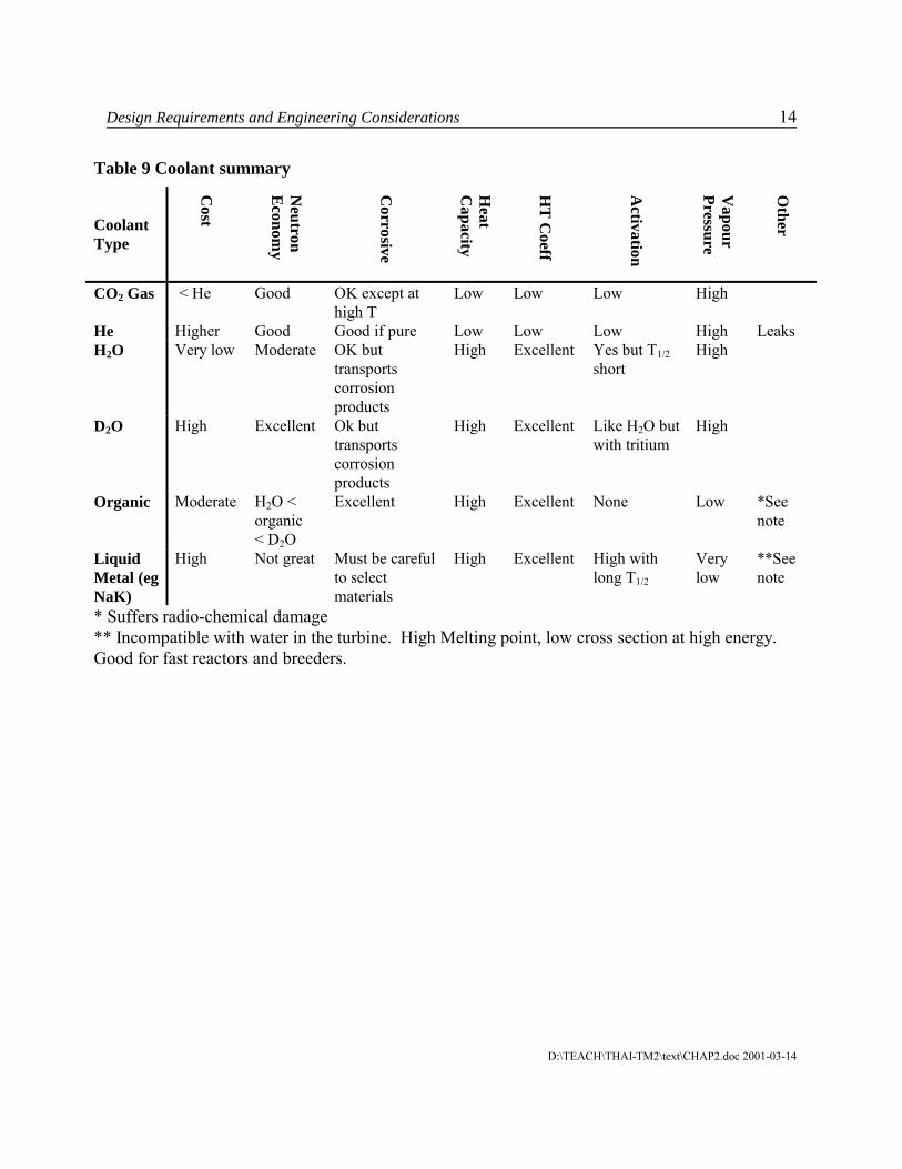
Table 9 Coolant summary
CoolantType
Cost
Neutron
Econom
y
Corrosive
Heat
Capacity
HT
Coeff
Activation
Vapour
Pressure
Other
CO2 Gas < He Good OK except athigh T
Low Low Low High
He Higher Good Good if pure Low Low Low High LeaksH2O Very low Moderate OK but
transportscorrosionproducts
High Excellent Yes but T1/2short
High
D2O High Excellent Ok buttransportscorrosionproducts
High Excellent Like H2O butwith tritium
High
Organic Moderate H2O <organic< D2O
Excellent High Excellent None Low *Seenote
LiquidMetal (egNaK)
High Not great Must be carefulto selectmaterials
High Excellent High withlong T1/2
Verylow
**Seenote
* Suffers radio-chemical damage** Incompatible with water in the turbine. High Melting point, low cross section at high energy. Good for fast reactors and breeders.

Design Requirements and Engineering Considerations 15
D:\TEACH\THAI-TM2\text\CHAP2.doc 2001-03-14
8 Neutron Moderators
The most current power reactors are of the thermal type, i. e. , where the energy of the neutrons causingfission is in the thermal range. Since the neutrons produced by the fission process have very high energies,it is necessary that they be slowed down, or "thermalized". The medium emploved for this is termed themoderator. It is deployed as a continuous medium surrounding the fuel "cells". The fuel cells form ageometric pattern, termed the reactor "lattice". The optimum spacing between these fuel cells is a functionof several variables including the mass of fuel per cell, the mean free path of the neutrons in beingthermalized, the degree to which the moderator wastefully absorbs neutrons, the cost of the moderatingmedium, etc.
The best moderator is something that is the same size as a neutron, ie, the hydrogen atom, 1H1. However,hydrogen does absorb neutrons as well. The deuterium atom, 2H1 , at twice the mass of hydrogen, isalmost as good a slowing down agent but, since it already has an extra neutron in the nucleus, it has a verylow absorption cross section. So, overall, it deuterium is a far better moderator than hydrogen. By usingdeuterium in the form of heavy water, natural uranium can be used as a fuel. If ordinary water is used, thefuel must be enriched in 235U.
A good moderator has a high scattering cross section, a low absorption cross section and slows down theneutron in the least number of collisions (high lethergy, ξ). Table 7 summarizes this. The "figure of merit"is defined as ξΣs / Σa.
Before discussing practical moderators, it is firstly useful to consider desirable properties of moderators. These are listed in table 8. Table 9 then lists the moderators currently used in commercial power reactors.
Table 10 Slowing down parameters of typical moderators [Source: DUD76, table 8-1]
Table 11 Desirable features of moderators1. HIGH MODERATING EFFICIENCY2. LOW NEUTRON ABSORPTION3. FREEDOM FROM DAMAGE - IRRADIATION, CORROSION4. LOW COST - RAW MATERIAL, MANUFACTURE, INSTALLATION

Design Requirements and Engineering Considerations 16
D:\TEACH\THAI-TM2\text\CHAP2.doc 2001-03-14
Table 12 Alternative power reactor moderators1. GRAPHITE2. ORDINARY WATER3. HEAVY WATER
Graphite has been widely used as a moderator for power reactors. The carbon atom is relatively "light",graphite is relatively inexpensive, and carbon is a relatively weak absorber of neutrons. Nevertheless, thecarbon atom is sufficiently large, leading to relatively long neutron mean free paths for thermalization, thatgraphite moderated reactors tend to be large. Furthermore, the relatively large amount of graphite requiredleads to significant neutron wastage through absorption.
Ordinary water is a much more efficient moderator in terms of the neutron mean free path forthermalization because of its hydrogen atoms. It is also very inexpensive. Unfortunately, however,hydrogen also has a significant "appetite" for absorbing thermal neutrons which hurts neutron economy.
Heavy water is almost as good as ordinary water in terms of neutron mean free path since the deuteriumatoms (which replace the hydrogen atoms in ordinary water) are relatively "light". Its outstandingadvantage, relative to ordinary water, is that it has a very small "appetite" for absorbing neutrons. Hence, itpromotes a high level of neutron economy. Its major disadvantage is its high cost.
Table 13 Moderator summaryModeratorType
Cost NeutronEconomy
Moderatorefficiency,
Irradiationstability
Activation MeanFreePath*
Graphite OK H2O <graphite< D2O
192 Excellent Irrelevant Long
H2O Verylow
Moderate 71 Excellent Good Small
D2O High Excellent 5670 Excellent Good Medium
* Mean free path determines the size of the core
s
a
ξΣΣ

Design Requirements and Engineering Considerations 17
D:\TEACH\THAI-TM2\text\CHAP2.doc 2001-03-14
9 Moderating Arrangements
How do the fuel, the coolant, and the moderator "fit" together to form practical power reactors? Thecurrently established alternatives are shown in Figure 5. If ordinary water is used as both coolant andmoderator, it is practical to arrange the fuel "rods" in cluster assemblies as shown. The clusters abutagainst each other. The space between the individual fuel rods is occupied by ordinary water which acts asboth moderator and coolant. A relatively small volume of water is required because of the very shortneutron mean free path with a hydrogen-based moderator. Hence, the fuel rods can be located relativelyclose to each other. This arrangement is used in both PWRs and BWRs.
If graphite (a solid) is used as the moderator, it is possible to arrange the graphite and fuel into abuttingcomposite assemblies.
Coolant passages are arranged through the fuel rods (annular form) or through the graphite. The formerapproach is used in one Russian reactor type where the coolant is water and steam (for superheating). Thelatter is used in HTGCR's where the coolant is helium and the fuel is uranium carbide, permittingextremely high fuel operating temperatures.
A third arrangement is where the fuel is in the form of assemblies completely separated from themoderator. This arrangement is used in heavy water moderated and most graphite moderated reactors.
The choice between these alternatives is influenced by many factors, both of a neutron physics nature and apractical engineering nature, and is very dependent on the particular choice of fuel, coolant and moderator.
Time does not permit a detailed discussion of all of these, although many of the factors have been touchedon in a qualitative way in the preceding sections. Most of the rest, also in a qualitative way, will betouched on in the next section which deals with specific power reactor types.

Design Requirements and Engineering Considerations 18
D:\TEACH\THAI-TM2\text\CHAP2.doc 2001-03-14
Figure 5 Moderating arrangements

Design Requirements and Engineering Considerations 19
D:\TEACH\THAI-TM2\text\CHAP2.doc 2001-03-14
10 HTS Design Requirements and Engineering Considerations
This section introduces the heat transport system and associated systems by a discussion of designrequirements and engineering considerations which guide the design of systems to transfer fission heat tothe coolant for the production of steam.
The fissioning process results in heat generation in the nuclear fuel and surrounding media. This thermalenergy can be utilized to produce electricity or process steam by the use of a heat transport medium, thecoolant. Here we will discuss some of the thermalhydraulic features which characterize the CANDUsystem, but the story is similar for PWRs..
The main objectives of the heat transport system are to provide heat transfer at high thermal efficiency andto allow the maximum amount of energy to be extracted from the fuel without surpassing safe limits.The requirements for such a system can be summarized as follows:
a) Due to the decay heat produced by the fuel even when the reactor is shut-down,continuous coolant flow must be provided. This leads to the requirement for pumps, pumpflywheels, standby cooling, thermosyphoning, etc.
b) Costs should be minimized with due regard for the other requirements. This usually leadsto trade offs between, for example, heavy water (D2O) costs, pumping power costs,equipment and piping size and costs, layout and engineering constraints.
c) Layout should minimize man-rem exposure and maximize maintainability andaccessibility within the constraints of other considerations.
d) Provision must be made for pressure and inventory control of the heat transfer system. Excessively high pressure could damage the fluid boundaries (pipes, etc.). Low pressurecould lead to high coolant voiding and possible fuel damage and to pump damage fromcavitation. Low inventory jeopardizes coolant circulation and pressure control.
e) The system must be sufficiently reliable since downtime leads to high replacement energycosts, high man-rem exposure and repair costs.
f) The design should provide high process efficiency.g) The system should exhibit ease of constructibility to reduce initial costs and time of
construction, and to enhance maintainability.h) The system should meet and, preferably surpass all safety and licensing requirements.
Various coolants can be used in the CANDU design to achieve the above objectives and requirements.Any nuclear station design employs a tradeoff in design features to best achieve the lowest cost powerwithin the safety limits. The U.S. nuclear industry, for instance, because of the availability of enricheduranium from existing UF6 diffusion plants, chose to use enriched uranium and H2O coolant in order toachieve the necessary neutron economy.
From a neutron economy viewpoint, the medium surrounding the fuel, ie., the coolant and the moderator,must not absorb neutrons and must moderate the neutron energy by a minimum of collision interactions. D2O is by far the best moderator/coolant from this viewpoint. The cost, however, is high at approximately$300/kg in 1980 dollars.Using H2O as the coolant, as in the CANDU-BLW, Gentilly-1, gives poorer neutron economy than the

Design Requirements and Engineering Considerations 20
D:\TEACH\THAI-TM2\text\CHAP2.doc 2001-03-14
CANDU-PHW and requires booster rods for startup until the positive void coefficient of reactivity adds asufficient positive reactivity to maintain criticality. Because of this and because of reactivity controldifficulties associated with the large void coefficient of reactivity, no new commercial CANDU-BLW's areplanned. Organic coolant, Monsanto OS-84, requires slightly enriched fuel (1.2 to 2.4 wt%). This optionwas found feasible but, due to the success of the CANDU-PHW, no commercial OCR's are planned.
Another nuclear consideration is that the coolant should have a low induced radioactivity. Both H2O andD2O produce N-16 and 0-19 which emit γ's in the 6-7 MeV range. This leads to reduced accessibility andmaintainability while on power. the short half life (<1 minute) allows shutdown accessibility. Tritium, H3
or T, has a 12 year half life and represents a major dose commitment for the station. Since tritium is a βemitter, the problem is one of leakage, leading to possible absorption/ingestion by humans. Organiccoolant has very little induced reactivity and aids in ease of operations, accessibility, etc.
The coolants should also be stable in a radiation environment. At the high system pressure of the heattransport systems of H2O and D2O, radiolysis is not a problem. However, since hydrogen and deuteriumhave a tendency to diffuse through the pipework, the heat transport system becomes concentrated inoxygen and enhances corrosion. Supplying an excess of hydrogen or deuterium prevents this occurrenceby driving the chemical equilibrium balance towards the associated state.
Organic coolant is more susceptible to radiolysis and requires degassing and makeup.
The choice of coolant also depends on other factors, such as pumping power, heat capacity, heat transfercoefficients, flowrates, pressure drop, boiling point, freezing point, corrosion, flammability, thermalstability, and cost.
Water (both D2O and H2O) is an attractive heat transport fluid since it offers a good balance of the aboveconsiderations. The specific heat, density and thermal conductivities are high compared to alternativessuch as N2, CO2 and OS-84 (organic). Since pumping power is given by:
Pumping power = pressure drop x volumetric flow rate,water requires less pumping power for a given heat removal.
For the Bruce reactors (which generate about 750 MWe), approximately 24 MW's of pumping power arerequired for each reactor. Of this 24 MW, roughly 90% (or 2l.5 MW) ends up in the primary heattransport system as heat due to friction. At an overall station efficiency of 30%, the net unit load forpumping power is 24 - 21.5 MW (bearing and windage losses) plus 2l.5 x .7 = 15 MW (rejected energy)for a total of 18.5 MW. This represents over 2% of the electrical power generated. Since MW saved hereby reducing pumping power is gained as electrical output, considerable emphasis is placed on loweringpumping power.
Limiting flowrates for water depend on many factors such as temperature, the presence of boiling, waterchemistry, geometry and flow regime. Fretting considerations have led to a 10 m/sec limit on fuel channelvelocity in single phase water. Erosion/corrosion considerations have led to 4.3 to 6.1 m/s (14 to 20 ft/s) inthe steam generator tubes and 16.8 m/s (55 ft/s) in heat transport piping. These limits may change as moreis learned about the limiting phenomena.
The fuel distribution in the coolant is such to maximize the surface to volume ratio of the fuel so that thehighest heat transfer surface can be exposed to the coolant for maximum heat transfer without drying outthe fuel surface. However, if carried to extremes the fuel volume in the core will be lower than optimum

Design Requirements and Engineering Considerations 21
D:\TEACH\THAI-TM2\text\CHAP2.doc 2001-03-14
and parasitic neutron absorption due to the sheath will increase. Present designs employ 37 or 28 elementsin a fuel bundle.
The use of boiling in the coolant permits higher heat transfer due to the high heat transfer coefficient ofpost-nucleate boiling.
Ideally, the coolant temperature should be as high as possible for maximum overall thermal efficiency. Thus a high boiling point, low vapour pressure liquid is desirable so that the heat transport system can beat the lowest possible pressure. This reduces the thickness of the pressure boundary and thus is importantfor reducing the parasitic burnup in the core. Organic coolant is far superior to water from this point ofview.
For the case of organic coolant, the secondary side H2O pressure is higher than the primary side OS-84pressure. Thus boiler tube leaks will cause a water leak into the primary coolant system.
Freezing point concerns for H2O and D2O are minor. For OS-84 provision must be made to preventfreezing while shutdown and cold. Continuous coolant makeup reduces this problem.
Corrosion of the heat transport system materials must be minimized because of possible deterioration, flowrestrictions and contamination with active isotopes.
The CANDU-PHW heat transport system has water coolant, low cobalt carbon steel piping, stainless steelend fittings, zircalloy pressure tubes and Monel or Incoly steam generator tubes. A pH of 10.2 to 10.8 ismaintained by lithium hydroxide. Hydrogen gas is added to keep the dissolved oxygen content low to helpminimize corrosion. The intent is to produce and maintain a continuous and adherent film of magnetite onall the carbon steel surfaces. Corrosion with organic coolant is a lesser problem, controlled by degassing,by using N2 cover gas, and by a dechlorinator system.
No flammability or thermal stability problems exist with water (except for the possible Zr-water reactionproducing H2 during a LOCA giving the potential for H2 explosion) but organic coolant is combustible,although it will not sustain combustion on its own. Organic coolant is also not as thermally stable as water.
The current cost of D2O ($300/kg - 1995 dollars) is high, making it the more expensive coolant. Thiscontributes to a high capital cost for the CANDU-PHW but a low operating cost due to the efficient use ofnatural U.

Design Requirements and Engineering Considerations 22
D:\TEACH\THAI-TM2\text\CHAP2.doc 2001-03-14
11 Power Reactor Types
It is not much of an exaggeration to state that in the early days of power reactor development there werechampions for every possible combination of the fuels, coolants, moderators, and moderator arrangementsdiscussed in the preceding sections and a few more besides. Many of these have fallen by the wayside,either because of basic, inherent shortcomings or, in some cases, because their champions could not rallyadequate support. This is, of course, natural with an emerging technology. A number of the possiblecombinations have reached the point of commercial exploitation. These are described briefly in thefollowing subsections.
11.1 "Magnox" Reactors
These are graphite moderated, CO2 gas cooled reactors fuelled with natural uranium metal clad with amagnesium alloy called Magnox. They have derived their generic name from this latter feature. Figure 6shows a schematic arrangement of one version of this reactor type.
This type of reactor was pioneered by the British and French and was a natural outgrowth of earlier air-cooled, graphite-moderated research and plutonium production reactors. A significant number were builtin Britain and France with a few exported to other countries. Early versions used steel reactor pressurevessels with external heat exchangers (boilers) and gas circulating blowers. Later versions, as per Figure 6,employed prestressed concrete pressure vessels incorporating the reactor core, heat exchangers and coolantcirculation blowers. This was primarily a cost reduction measure, although safety advantages in terms ofrisk of coolant system rupture were also claimed (likely valid).
Primarily because of coolant temperature limitations imposed by the uranium metal fuel and the Magnoxcladding, only relatively modest turbine steam conditions are achievable, limiting the station overallefficiency to ~ 30%.
Figure 6 Schematic arrangement - Gas Cooled Reactors

Design Requirements and Engineering Considerations 23
D:\TEACH\THAI-TM2\text\CHAP2.doc 2001-03-14
As is typical of all natural uranium power reactors, the Magnox reactors are fuelled on-load. This isbecause large quantities of excess reactivity, in the form of additional U-235, is not "built into" the newfuel.The in-service availability of the Magnox reactors has proven to be relatively good. On-load refuellinghelps in this regard. Nevertheless, their relatively high capital cost and relatively modest achievable fuelutilization has led to the discontinuation of construction of further reactors of this type.
11.2 AGR
The AGR (advanced gas cooled reactor) has been developed in the U. K. as a successor to their Magnoxline of reactors. Several are now under construction. They differ from the latest Magnox reactorsprimarily in the fuel used. The fuel is UO2 clad in stainless steel. This permits rather higher fueltemperatures and, hence, coolant temperatures to be achieved, leading to conventional fossil fuel steamconditions (2400 psi, 1025 ºF/1025 ºF). The fuel is in the form of a cluster of small diameter rods,permitting relatively high power levels to be achieved. This reduces the size of the reactor core relative tothe Magnox reactors where the fuel is in the form of large single elements. However, because of these fuelchanges, the AGR requires some fuel enrichment.
Figure 6 also applies to the AGR reactor type.
The British currently appear to have decided that the AGR is not fully competitive with some other typesof power reactors. Hence, this design, like the Magnox type, appears to be "dead-ended".
11.3 HTGCR
This type represents the next evolutionary step in the Magnox-AGR line of gas-cooled, graphite-moderatedreactors. It is being developed by Gulf General Atomic in the U.S. and by the West Germans and British.
The HTGCR differs from the AGR in two major respects. The first is the use of helium as the coolant inplace of CO2. This permits even higher coolant temperatures without inducing a chemical reaction withthe graphite moderator. The second relates to the fuel. The fuel uses fully enriched (93%) U-235 mixedwith thorium. Thorium absorbs neutrons and is converted, after a radioactive decay chain, to U-233 whichis fissile. As a result, the reactivity of the fuel remains high even after very long irradiation, the U-233replacing the U-235 as the latter is burned up. Their fuel is in the form of mixed carbides. It ismanufactured in very small spheres which are coated with pyrolytic graphite, the latter providing thecladding. These spheres are compacted into holes in large graphite assemblies, forming an integral fueland moderator assembly as per Figure 5.
The very high achievable coolant temperatures lead to high steam cycle efficiencies, or alternatively, makepossible the ultimate use of gas turbines directly driven by the coolant. Figure 6 applies to the formerapproach since the basic system is the same as for the Magnox and AGR concepts.
The fuel probably represents the major development problem yet to be completely solved in terms ofachieving attractive long-term fuelling costs. This reactor type, because of its high thermal efficiency,would see some preference in areas where waste heat rejection presents a particular problem. Thedevelopment of the direct cycle gas turbine version would be particularly attractive in this regard.

Design Requirements and Engineering Considerations 24
D:\TEACH\THAI-TM2\text\CHAP2.doc 2001-03-14
11.4 PWR
The PWR (pressurized water reactor) has, to date, been the world's most widely accepted power reactortype. It got its start in the development of the PWR propulsion reactors for the U. S. nuclear submarines.
In this type of reactor, ordinary water is used both as the coolant and the moderator. The fuel is in the formof clusters of enriched UO2 rods clad in zirconium alloy or, in some cases, austenitic stainless steel. Theseclusters are square in shape, i.e., the rods form a square array in each cluster assembly, with the clusters, inturn, being closely packed in a square array forming the reactor core, see Figure 5. As is shown in Figure 7,the reactor core is located in a large steel pressure vessel. The water coolant at high pressure (~ 2000 psi)is circulated by external pumps into the reactor vessel, flows upwards through the fuel clusters, out of thevessel to heat exchangers, and from the heat exchangers back to the pumps. On the secondary side of theheat exchangers, water is boiled forming saturated steam which drives the turbine. This steam is generatedat ~ 750 psi, leading to a relatively low overall station efficiency (~ 30%).
In order to refuel the reactor, it must be shut down, cooled out and depressurized. The top of the pressurevessel is then removed and the fuel assemblies changed. This refuelling is normally done annually. Inorder to operate for long periods without refuelling, the new fuel is relatively highly enriched in U-235.
While the fuel is new, the excess reactivity in the core is compensated for by a neutron poison dissolved inthe coolant/moderator water. As the fuel burns up, the poison is gradually removed by ion exchangecolumns.
Figure 7 Schematic arrangement - PWR

Design Requirements and Engineering Considerations 25
D:\TEACH\THAI-TM2\text\CHAP2.doc 2001-03-14
11.5 BWR
The BWR (boiling water reactor) is second only to the PWR in terms of world-wide acceptance. It issimilar in many respects to the PWR, the basic difference being that the light water coolant is permitted toboil in the reactor core. The steam thus produced is separated from the coolant water by centrifugalseparators located in the reactor vessel above the core and fed directly to the turbine at ~1000 psi pressure. The general arrangement is as shown in Figure 8.
With this arrangement, the turbine plant is "active" because of activity induced in the reactor coolant(primarily N-16). As a result, the turbine plant is more or less inaccessible during operation; fortunately,however, this activity dies out quickly following shutdown, permitting normal direct access maintenance.
While the BWR appears simpler than the PWR, it has not been able to secure a clear economic advantageover the latter. The two types have run "neck and neck" in the acceptance race for years, both in the U.S.and in many other countries.
Figure 8 Schematic arrangement - BWR
11.6 LMFBR
Before discussing the last major current commercial type of power reactor, I would like to briefly describethe liquid metal cooled fast breeder reactor (LMFBR). While no reactors of this type are currently incommercial operation.
Firstly, a few "basics". All of the previously described reactors are of the thermal type, i.e., the fissions inthe fuel are primarily induced by thermal neutrons. It is, however, possible to sustain a chain reaction withhigh energy, i.e., fission, neutrons, provided the fuel is highly enriched with fissile material such as U-235or Pu-239. Furthermore, an average of rather more than two neutrons are born from each fission. One of

Design Requirements and Engineering Considerations 26
D:\TEACH\THAI-TM2\text\CHAP2.doc 2001-03-14
these neutrons is required to induce the next fission, leaving a surplus of rather more than one neutronwhich can be absorbed by a "fertile" material such as U-238, producing fissile Pu-239. We can producefissile material as rapidly as we use it up. This is called "breeding". In fact, it is possible to produce morefissile material than is used because the average number of neutrons produced per fission is >2. Theexcess is referred to as the "breeding gain". Clearly this can only be done if the neutron economy is high,i. e. , relatively few neutrons are wasted.
This possibility of breeding is very attractive as a means of extending the power available from uraniumsince, as you will remember, less than 1% of natural uranium is fissile. If a substantial part of the other~99% can be converted to fissile Pu-239 as a byproduct of reactor operation, then the world's uraniumreserves can be stretched enormously. The fast breeder reactor is one way of doing this; hence, thewidespread interest in this concept.
The basic arrangement of a liquid metal cooled fast breeder reactor is shown in Figure 9. The reactor coreconsists of a closely packed array of highly enriched (U-235 or PU-239) oxide rods clad in a hightemperature resistant metal. This core is surrounded on all sides by a "breeder blanket" of fertile U-238(also in clad oxide form) rods. The excess fission neutrons produced in the core "leak" out of the core andare absorbed in the blanket rods. Both the core and blanket are cooled by a flow of liquid sodium. Thissodium is, in turn, cooled in heat exchangers and returned to the reactor by more or less conventionalcentrifugal pumps. The heat exchangers are cooled by a second flow of sodium which, in turn, is cooled ina second set of heat exchangers which produce steam for the turbine. The purpose of this intermediatesodium loop is to provide completely positive isolation between the sodium cooling the reactor and theturbine cycle steam and water, thereby ensuring that an inleakage of water cannot contaminate the reactorcoolant.
Despite this intermediate loop, the reactor operating temperature is sufficiently high to permit steam to beproduced at modern fossil fuelled plant conditions (~-2400 psig and 1000 ºF with single reheat to 1000ºF).
Figure 9 Schematic arrangement - LMFBR
Design Requirements and Engineering Considerations 27
D:\TEACH\THAI-TM2\text\CHAP2.doc 2001-03-14
Because of the complex economies and technical problems associated with the LMFBR, while manypeople feel this is the "reactor of the future", it is probable that the future in this case will be quite a fewyears in coming.
11.7 CANDU
This, as you know, is the generic name for the Canadian heavy water moderated, natural uranium typepower reactor. You will notice that there is no coolant specified in this definition. This is because avariety of coolants can be used.
All CANDU reactors possess certain basic characteristics and features as follows:
11.7.1 Neutron EconomyThis is the keystone of the concept. If natural uranium fuel is to be used economically, high burnups mustbe achieved, i. e., the megawatts extracted per kilogram of uranium must be high. This led to the choice ofheavy water as the moderating medium since heavy water is by far the most neutron economic moderatoravailable.
11.7.2 Pressure TubesWhile it is possible to use heavy water in a PWR type of pressure vessel reactor as both the coolant andmoderator, the size of pressure vessel required is rather larger than for a PWR because the required volumeof D20 moderator is much greater than the required volume of H20 moderator. The early studies ofCANDU reactors were based on the pressure vessel approach and, in fact, NPD started out to be a pressurevessel type. It was, however, recognized that the size of pressure vessel manufacturable in Canada at thattime would be quite limited, placing a definite limit on the power output achievable when the firstcommercial units were built. At the same time, the development of zirconium alloy (a neutron economicalmaterial) had proceeded to the point where it became possible to employ this material for pressure tubes. Before proceeding to describe the pressure tube approach, I should say that the pressure vessel approachwas followed by Sweden and Germany for some years and is still being followed by Kraftwerk-Union for aplant they built in Argentina.
The pressure tube reactor concept can be described as follows. The reactor consists of an array of pressuretubes, generally arranged on a square lattice, which pass through, from end to end, a large cylindrical tank. The reactor fuel, in the form of cylindrical clusters of individual fuel rods, resides inside the pressuretubes. The coolant is pumped through the pressure tubes to cool the fuel. The fact that this coolant isgenerally at high pressure gives rise to the term "pressure tube".
The heavy water moderator is held in the large cylindrical tank which surrounds the pressure tubes. Thislarge cylindrical tank is called the calandria. Because the coolant, and hence the pressure tubes, mustoperate at high temperature in a power reactor and because it is desirable to operate the moderator at lowtemperature to avoid the necessity of pressurizing the calandria, the pressure tubes must be insulated fromthe moderator. This is done by introducing a second tube which surrounds the pressure tube but isseparated from it by a stagnant gas space. This second tube is called the calandria tube. This calandriatube is sealed at both ends to the calandria end plates or tubesheets, thereby completing the moderatorcontainment.With this arrangement the fuel coolant is completely separated from the moderator, permitting a free

Design Requirements and Engineering Considerations 28
D:\TEACH\THAI-TM2\text\CHAP2.doc 2001-03-14
choice of coolants.
11.7.3 On-Power Fuelling
If natural uranium fuel is to be employed and high burnups achieved, neutrons must not be wastedneedlessly. This is best achieved by introducing new fuel and removing old, burned-up fuel in a"continuous" manner since the excess reactivity possessed by the new fuel can be used to compensate forthe loss of reactivity on the part of the old fuel, thereby extending its useful life.
The pressure tube approach lends itself to on-power refuelling since the fuel residing in individual pressuretubes can be changed without affecting other pressure tubes or the fuel in them.
11.7.4 Separate Moderator
As was mentioned earlier, the pressure tube approach used in CANDU reactors permits the heavy watermoderator to be kept quite separate from the fuel coolant. This, in turn, permits the moderator to beoperated at a low temperature, which has several advantages:
• the calandria can operate at atmospheric pressure, avoiding the need for a heavy, highpressure vessel
• the cold moderator can act as a valuable heat sink under certain accident conditions.• since the moderator is cold it cannot add energy to the reactor containment under accident
conditions. This reduces the total quantity of energy which the containment system musthandle.
In the foregoing, I have described certain general features common to all CANDU reactors. I will nowdiscuss the various types of CANDU reactors developed to date.
11.8 CANDU-PHW
This is the pressurized heavy water (PHW) cooled version. It was the first type developed and is by far themost widely used. While not inherently necessary, this version has to date always employed a horizontalreactor core orientation. Vertical versions have been studied a number of times but no clear incentive toswitch to this orientation has been identified.
A schematic arrangement of the PHW version is shown in Figure 10. Pressurized (~ 1400 psi) heavy watercoolant at~ 480ºF is supplied to each fuel channel (an assembly consisting of the zirconium alloy pressuretube with an alloy steel fitting attached at each end) via an individual pipe, called a feeder pipe. As thecoolant passes through the fuel channel it picks up heat from the fuel and leaves the channel at ~560ºF. Itis then conveyed to the outlet header via the outlet feeder pipe. From the outlet header, the coolant flowsthrough the boiler heat exchangers where it is cooled back to ~ 480ºF, its heat being given up to producesteam at ~ 600 psi which is fed to the turbine. The coolant then enters the circulating pumps which deliverit to the reactor inlet header and, thence, to the inlet feeder pipes.
A separate auxiliary circuit is employed to circulate the heavy water moderator through external heat

Design Requirements and Engineering Considerations 29
D:\TEACH\THAI-TM2\text\CHAP2.doc 2001-03-14
exchangers. These reject to the station cooling water the heat generated in the moderator by the slowingdown of the neutrons, by the effects of γ radiation, and also the heat leaking into the moderator across theinsulation gaps between the calandria tubes and pressure tubes.

Design Requirements and Engineering Considerations 30
D:\TEACH\THAI-TM2\text\CHAP2.doc 2001-03-14
Figure 10 CANDU PWR schematic

Design Requirements and Engineering Considerations 31
D:\TEACH\THAI-TM2\text\CHAP2.doc 2001-03-14
11.9 CANDU-BLW
This was the second version of the basic CANDU concept to reach the prototype reactor stage (the 250MWe Gentilly plant). Its major difference lies in the choice of coolant: boiling light (ordinary) water,hence BLW. Its reactor coolant and turbine systems are fundamentally the same as those of the BWRdescribed earlier, i.e. , a direct cycle is employed.
For this version, a vertical orientation was chosen. There were a number of detailed considerations relatingto the boiling coolant which led to this choice. It is likely that future CANDU-BLW reactors will retainthis orientation. Design details of the reactor proper will be described later.
Figure 11 provides a schematic illustration of the concept. Ordinary water is pumped to the bottom of eachfuel channel via an individual feeder pipe. As the water passes upwards and absorbs heat from the fuel, afraction (~ 18%) is evaporated to steam. The resulting steam/ water mixture then flows to a conventionalsteam drum where the steam and water are separated. The steam then flows to the turbine and the water,mixed with incoming feedwater in the drum, flows down to the circulating pumps, completing the cycle.
The moderator cooling system is basically the same as for the PHW version.
The British have developed a similar version which they call the SGHWR (steam generating heavy waterreactor). A 100 MWe prototype has been built and is in operation. It differs from our Gentilly prototypein that it uses slightly enriched fuel. This permits rather less heavy water moderator to be used, reducingcapital costs. The fuelling costs are, however, somewhat higher. Another possible variation is one inwhich the enrichment is provided by plutonium which is produced as a by-product in the fuel used in ourPHW reactors. This plutonium, as plutonium oxide, would be mixed with natural UO2 in the fuel.
11.10 CANDU-OCR
A third version of the basic CANDU concept is one which would use an organic fluid as the coolant. Itwould be similar to the PHW concept except that the boilers would likely be of the "once-through" typewith some steam superheating provided. This is made possible by the fact that the coolant temperature atthe reactor outlet can be ~ 100 ºC higher than in the case of heavy water cooling.
The WR-1 experimental reactor at our Whiteshell establishment employed this concept except that the heatis "wasted", i. e. , no turbine was provided. The reactor operated with coolant conditions which are thesame as would be employed in a commercial power plant.

Design Requirements and Engineering Considerations 32
D:\TEACH\THAI-TM2\text\CHAP2.doc 2001-03-14
Figure 11 Simplified station flow diagram - CANDU BWR
Design Requirements and Engineering Considerations 33
D:\TEACH\THAI-TM2\text\CHAP2.doc 2001-03-14
11.11 A Comparison Between CANDU Reactors and Other Types
Currently the major competitors to the CANDU system are the light water reactors (PWRs and BWRs).
With regard to the competitive position between current commercial reactors, CANDU-PHW on one handand the light water reactors on the other, neither type has a clear lead in all cases. This arises because ofdifferences in basic characteristics.
From the standpoint of fuelling costs, the CANDU-PHW is the clear winner. This is, of course, because itcan use natural uranium fuel whereas the light water reactors require enriched fuel. The enriched fuel ismore expensive in several regards. Firstly, there is the cost of producing the enriched UO2. This appearsboth as a "consumption" cost and as an added interest cost on the fuel while in manufacture, while residentin the reactor and while awaiting subsequent chemical reprocessing. Secondly, there is a manufacturingcost penalty because of the precautions necessary to avoid a criticality accident. Thirdly, there is a muchmore severe penalty should the fuel fail before achieving its full burnup life. Such failure is fundamentallymore likely with enriched fuel because its "economic" life (burnup) needs to be approximately double thatof natural fuel.
From the standpoint of capital costs, the picture is not as clear. The generally held view is that the capitalcost of a light water reactor will be considerably lower. This is at least partly attributable to the differencein the way that heavy water and enriched fuel costs are accounted for in common utility practice. Theformer is treated as a normal plant depreciating capital asset whereas, in fact, it does not really depreciate. The latter is not considered as a capital asset. The fact is, of course, that a large amount of somebody'smoney is tied up in the enriched fuel. This is not, however, always utility money although the utilityultimately pays for it in terms of interest charges as pointed out earlier.
There is another significant difference which, while real, is not inherently the result of differences betweenthe concepts. Relatively little advantage has been taken to date in the replication of design betweenCANDU plants. This is because relatively few have been built compared to PWRs. As a result, theCANDU reactors have been burdened with higher engineering costs and in costs arising from longerconstruction schedules because of relative inexperience. This difference is now diminished because wehave built a strong technological base which will permit the replication of most design features from plantto plant.
There is only one way in which a utility can really answer the question as to which type is best for it andthis is to go through a full comparative evaluation program based on its own requirements and financingposition. Certainly, capital costs quoted in technical journals, newspapers, etc., are meaningless becausethey are, of necessity, quoted "out of context".
From a purely technical standpoint, one cannot say that one type of reactor has a clear advantage over theother, whether this be in terms of safety, or availability, or ease of operation, or what have you. Forexample, the use of heavy water at elevated temperatures and pressures for the coolant in the CANDU-PHW imposes strict requirements on coolant system leak-tightness and on systems for recovering leakage. Leakage is, however, not greatly more tolerable in the light water cooled reactors, primarily because ofradioactive materials in the water. A, perhaps, compensating feature in another direction is that the on-load refuelling capability of the CANDU-PHW means that fuel defects are much more tolerable since thedefective fuel can be readily removed. In the case of the light water reactors, the removal of defective fuel

Design Requirements and Engineering Considerations 34
D:\TEACH\THAI-TM2\text\CHAP2.doc 2001-03-14
requires a plant shutdown of several weeks' duration.
One last point on the subject of comparisons. The CANDU-PHW is a "water reactor" as are thePWR's and BWR's. They therefore share many of the same advantages and problems. There isno question but that we, in developing the CANDU-PHW, have benefited greatly from much ofthe R & D work done for the light water reactors. Examples include UO2 fuel, zirconium alloys
for fuel cladding and reactor components, boiler heat exchangers, and main coolant pumps.

Design Requirements and Engineering Considerations 35
D:\TEACH\THAI-TM2\text\CHAP2.doc 2001-03-14
About this document: back to page 1
Author and affiliation: Wm. J. Garland, Professor, Department of Engineering Physics,McMaster University, Hamilton, Ontario, Canada, January 2001,
Revision history:Revision 0.0, September 28, 1998, initial creationRevision 1.0, March 14, 2001, switch from Word Perfect to Word, added some tables tosummarize the text, no new content.Source document archive location:D:\TEACH\THAI-TM2\text\CHAP2.docContact person: Wm. J. Garland
Notes: