Embed Size (px)
Citation preview

Energy Procedia 42 ( 2013 ) 270 – 279
1876-6102 © 2013 The Authors. Published by Elsevier Ltd. Selection and peer-review under responsibility of KES Internationaldoi: 10.1016/j.egypro.2013.11.027
ScienceDirect
* Corresponding author. Tél : +212 5 36 50 06 01/02, ; Fax : +212 5 36 50 06 03.E-mail address: [email protected].
The Mediterranean Green Energy Forum 2013, MGEF-13
Design, realization and optimization of the photovoltaicsystems equipped with analog and digital MPPT commands
E. Baghaz, M. Melhaoui, F. Yaden, K. Hirech, K. Kassmi*
Mohamed First Urr niversity, Faculty of Science, dept of Physics,UU Laboratory LETAS, Oujda, Morocco
Abstract
In this paper, we present experimental results of a photovoltaic system (PV) provided with two analog and digital MPPT commands. The disadvantage of these commands is that they are suffering from divergence problems caused by a sudden change in weather conditions (light, temperature,) or load variations. Therefore, we developed a CDCS circuit for the analog MPPT command to optimize thereliability of PV system independently of weather conditions changes or load variations. The functioningof the PV system during whole days shows a very good agreement between the experiment and theoptimal simulation of the electric properties of the PV panel (voltage, current and power). The low lossesof electrical energy produced by the PV panel (lower than 5 %) and the smooth functioning of the DC/DCconverter used (efficiency upper to 80 %) reveal the good functioning and reliability of the systems usingbboth types of MPPT commands conceived and realized during this work.
© 2013 The Authors. Published by Elsevier Ltd.Selection and peer-review under responsibility of KES International
Keywords: Photovoltaic System (PV), Photovoltaic Panels, Analog and Digital MPPT Commands, Losses of Energies, DC/DCconverters.
1. Introduction
The predictable exhaustion of the fossil fuels, the necessity of fighting against the global warming, theawareness for the protection of the environment and the consideration of the sustainable development inenergy policies put the renewable energies in the heart of a strategic stake for the future of our planet [1].Among the options of the renewable energies, there is an inexhaustible energy and still underexploited in our days: the solar energy. Indeed, the photovoltaic panels remain a real promise for the future [2-15].
One of the first difficulties engendered by the use of a photovoltaic panel is focused on the problem of the non perfect coupling between the PV generator and the load [2-7]. This can lead to important losses of
Available online at www.sciencedirect.com
© 2013 The Authors. Published by Elsevier Ltd. Selection and peer-review under responsibility of KES International
Open access under CC BY-NC-ND license.
Open access under CC BY-NC-ND license.

E. Baghaz et al. / Energy Procedia 42 ( 2013 ) 270 – 279 271
power and consequently the cost of the PV installations will be very high. At present, to minimize these losses, several studies are made on the analog and digital MPPT commands to converge the functioning point of PV generators around the maximum power point (PPM) [2-12,14]. The published results show, on one hand, the absence of the comparison of the results obtained to the optimal ones, and on the other hand, the divergence of the system after sudden variations of the solar radiation and the load.
In this frame, we propose the design, the realization, the experiment and the fine analysis of the PV systems provided with the analog and digital MPPT commands. Both types of MPPT commands take into account the detection of the system dysfunction and the convergence towards the PPM without restarting the system. From the simulation of the optimal electrical quantities (voltage, current and power), we have analyzed the feasibility and the losses of energies of the PV systems realized.
2. Photovoltaic Systems
1.1. Synoptic diagram
The synoptic diagram of the PV system provided with the analog and digital MPPT commands is shown in Figure 1.
The various blocks of the system are: The Monocrystalline silicon PV Panel which delivers in standard test conditions (STC) a power of 75
W, a current of 4.6 A and a voltage of 17V [2,15]. A load which can be either two batteries (115Ah, 12V) in series, or a variable resistor. In last case, the
resistor value is fixed to be superior to the optimal resistor of the PV panel for a given illumination and temperature [2].
A block of power formed by DC/DC energy converter (Boost converter) used for applications requiring voltage superior than the optimal voltage of PV panels [2-7]. Its power switch is controlled by a PWM signal at a fixed frequency of 10 kHz with a variable duty cycle α.
An analog or digital MPPT command (Maximum Power Point Tracking), allowing to pursue the maximal power point of the PV panel which depends on weather conditions and load variations. The
Nomenclature
PV Photovoltaic
Vpv Photovoltaic Panel voltage (V)
Vs Vs Output of the DC-DC Boost Voltage (V)
Ipv Photovoltaic Panel Current (A)
Le The solar radiation (W/m²)
Ppv Photovoltaic Panel Power (W)
α Duty cycle
CDCS Circuit of Detection and Convergence of the system
MPP Maximum Power Point
MPPT Maximum Power Point Tracking
PWM Pulse-With modulation

272 E. Baghaz et al. / Energy Procedia 42 ( 2013 ) 270 – 279
analog MPPT command is equipped with a Circuit of Detection and Convergence of the system (CDCS). Its purpose is to detect the system dysfunction (divergence of the system to close or open circuit conditions), further to a sudden variation of the illumination and to load variation. As a result,the circuit leads the power point of the PV system to converge to its new MPP without restarting thesystem [2,5].The digital MPPT command is provided with a buckle of divergence making the PVpanel always working to its optimal electrical quantities independently of the weather conditions (solar radiation, temperature) and the load variations.
Fig. 1. Synoptic diagram of the PV system equipped with the analog and digital MPPT commands.
2.2. MPPT Command
The Figure 2 and 3 represent the synoptic Diagram of PV systems equipped with the analog and digitalMPPT commands. The various blocks of the MPPT command are:
analog MPPT Command equipped with the CDCS circuit:A shunt resistor (R) of very low value which can support a current of 10A. the purpose of using thisresistor is to raise the image of current Ipv of the PV panel.A resistor bridge composed by two resistors “R1 and R2” to take a fraction of the voltage of the PV generator.A multiplier which supplies at its output the image of the immediate power delivered by the PV panel.Two integrators: one of them is faster with a constant time τR, and the other is slower with a constant time τL. The fast integrator delivers at its output the instantaneous power Pr supplied by the PV panel,and the slower integrator supplies at its output a delayed power Pl ( t+dt ). The comparison between these two powers (Pr and Pl) allows deducing the evolution sense of the system: increasing or decreasing power of the PV panel. At a given moment t, if the Pr power is superior (inferior) to the Plpower, we have an increasing (decreasing) power at the output of the PV panel.A comparator (1) which role is to make the comparison between the Pr power and the delayed Pl, andto supply a rectangular signal at its exit (+0, Vcc).A Flip-Flop whose Q output changes state on each rising edge of the clock signal which is the outputof the comparator (1). When the system evolves towards a lower power, the Q output changes its state,in order to reverse the direction of system evolution.Integrator (Ro, Co) using a capacitor which charges and discharges slowly. It delivers at its output a
voltage constituting the Vref voltage reference.A comparator (2) which generates a rectangular signal (PWM signal of variable duty cycle α),
DCDCDC/D/D/DCCC CCConononvevevertrtrterererBOBOBOBOOSOSOSOSTTTT LLLoLoLo ddadadad
AnAnalalogogg MMPPPPTTCoCoCoCommmmmmmmanananandddd
CDCDCDCDCDCSCSCSCSCSCiCiCiCiCircrcrcrcrcuiuiuiuiuittttt
PVPV PPaanenell SPSPSP757575
DiDigigig tatall MPMPPTPTCCoCoCommmmmmananandddd

E. Baghaz et al. / Energy Procedia 42 ( 2013 ) 270 – 279 273
resulting from the comparison between the Vref voltage and the one issued by an oscillator frequency of 10 kHz. The variation of α duty cycle depends on the Vref voltage: when Vref voltage increases (decreases), the duty cycle α increases (decreases).
The CDCS circuit is formed by two monostables to detect the divergence of the PV system. The inputs of these monostables are connected to Q and Qb outputs of the Flip-Flop of the MPPT command. If the system diverges, both Q and Qb outputs don’t change state. The output of one monostable detects the divergence if the system diverges to the closed circuit conditions and the output of the other monostable detects the divergence if the system diverges to open circuit conditions. the period of every monostable is:
T1=1.1*R3*C3 , T2=1.1*R4*C4 (1)
The outputs of the two monostables are connected to logic gate X-OR-type. If the system loses its optimum operating point, moments after T1 or T2, one of the two monostables changes state and accordingly, the output of X-OR gate changes its state. This shows that one of the monostables has detected the PV system dysfunction. The output of X-OR gate is then inverted by a logic inverter. This pulse is applied to the clock of another ‘Flip-Flop' and thus the change of state occurs at its Qc output. The switching of the signal at the inverter output, changes the position of the blade of a relay which connects the input of the RoCo integrator to both Q and Qb outputs of the MPPT command Flip-Flop. If the RoCo integrator is connected to the Q (Qb) output, then the detection of a dysfunction reconnects the RoCo integrator at the Qb (Q) output of the MPPT command Flip-Flop. This change in blade position of the relay induces change of direction of duty cycle variation of PWM signal generated by the MPPT command and thus, changes the direction of movement of the operating point of PV generator. This last movement allows the PV system converging to the new PPM following the sudden change in the solar radiation or in the load.
Digital MPPT command : The regulation of the power supplied by PV panels is made by the algorithm of the Figure 4. This algorithm for the PPM is based on Hill Climbing algorithm [3-4], whose principle is to calculate the power derivative and modify the duty cycle according to several parameters (Power derivative, end of delay time and the state of variable used in our program). By getting back the sign of the power derivative, we can determine where the system is situated with regard to the MPP. If the derivative is positive, we can conclude that the power point of the PV panels evolves through the MPP, thus we do not have to change the state of the variable Var. This variable contains two states, a high state " 1 " and a low state " 0 ", witch its purpose is choosing the direction of MPP search. In the other hand, if the power derivative is negative, we can conclude that the PPM is already exceeded. In this case, we test the state of the variable H which corresponds to an authorization to change Var state (H indicates if timer0 has finished the counting). So, the search direction is reversed by changing the Var state and only if the variable H is in a high state "1". After knowing the Var value, we generate via the features presented in the Microcontroller, a squared signal "signal PWM", that we can modify its duty cycle with a fixed frequency of 10 Khz. If the Var is in the high state, we increment the duty cycle, if not we decrease it. Therefore, the system oscillates around the MPP. Contrary to the other algorithms [5-6], our algorithm treats the problem of divergence. If there is a sudden variation of the solar radiation for example, we compare two successive powers to calculate the derivative. If the system evolves towards the maximal power point MPP, the algorithm works then as described above. On the other hand, if the system does not evolve towards the PPM, the algorithm will invert the state of the variable Var after a determined delay has elapsed, avoiding problems

274 E. Baghaz et al. / Energy Procedia 42 ( 2013 ) 270 – 279
PV PanelSP75
DC/DC Boost Converter
Rsh
R1
R2
MicrocontrollerPIC16F877
MOSFET Driver Inverter Amplifier
Amplifier
Load
related to the errors during the conversion or to the divergence of system during a sudden change ofthe solar radiation or the load.
Fig.2. Synoptic diagram of the PV system equipped with the analog MPPT command and the CDCS Circuit.
Fig. 3. Synoptic diagram of the PV system equipped with the digital MPPT command.
R3R
Trigger
RShuntVpv
MultiplierRC slow
Threshold
Trigger
Monostable 4
Monostable 3
Threshold
RelayFlip -Flop
H Q
INVX-OR
R4
C4
Vcc
CDCS Circuit
C3
Vcc
Comparator 1
R1
Driver
Generator
Flip-FlopQ
Qb
Integrator (Ro,Co)
RCFast
Ipv
PV Panel Load
R2R
VsDC-DC BOOST
Converter
+
-
Amplifierp
+
-
Comparator 2p
+
-
MPPT
E. Baghaz et al. / Energy Procedia 42 ( 2013 ) 270 – 279 275
Fig. 4. Digital MPPT command algorithm.
3. Experimental Results
3.1. Experimental procedures
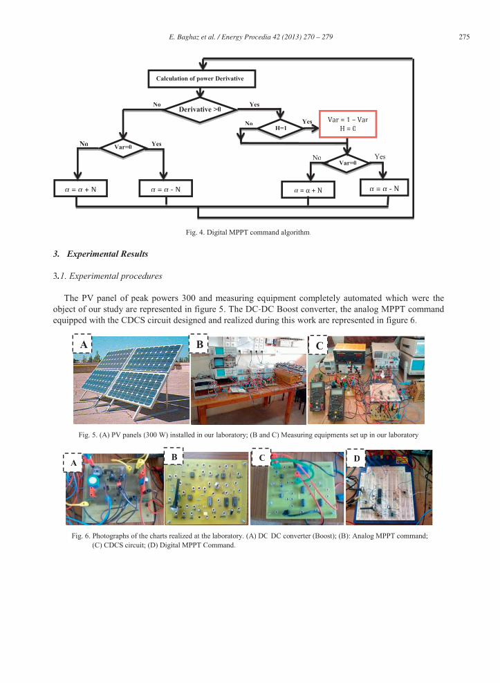
The PV panel of peak powers 300 and measuring equipment completely automated which were theobject of our study are represented in figure 5. The DC-DC Boost converter, the analog MPPT commandequipped with the CDCS circuit designed and realized during this work are represented in figure 6.
Fig. 5. (A) PV panels (300 W) installed in our laboratory; (B and C) Measuring equipments set up in our laboratory
Fig. 6. Photographs of the charts realized at the laboratory. (A) DC-DC converter (Boost); (B): Analog MPPT command;(C) CDCS circuit; (D) Digital MPPT Command.
Yes
Calculation of power Derivative
NoDerivative >0
No Yes
α = α + N α = α - N α = α + NYesNo
α = α - N
Var = 1 – VarH = 0Var=0
NoH=1
Yes
Var=0
A B C
A B C D

276 E. Baghaz et al. / Energy Procedia 42 ( 2013 ) 270 – 279
3.2. Characterization and optimal simulation of the PV panels functioning
We have characterized the SP75 panel during a day when the solar radiation intensity varies from 300 W / m² to 900 W / m² and the temperature from 22°C to 25°C. In figure 7, we have represented the typical experimental characteristics current-voltage and obtained powers-voltage. On the same figures, we have represented the characteristics obtained in Pspice by fixing the parameters of the diode (current of saturations) which allows having a good agreement between the experiment and the simulation. The final results show a good agreement between the experiment and the simulation.
From the characteristics of figure 7, we have represented in figure 8 the variation of the optimal voltage (Vopt) of the panel as function as the solar radiation. It seems that for this temperature 20-25°C, the optimal voltage Vopt decreases linearly with the solar radation. When the solar radiation varies from 300W/m² to 900 W / m², the optimal voltage varies from 14.8 V to 13.2 V (11 % decreasing).
Fig. 7. Experimental ( , ∆, ) and simulated in Pspice (——) Power-Voltage and
current-Voltage characteristics. T, 22 to 25°C.
Fig. 8. Variation of the optimal voltage( Vopt) of the PV panel as function as the solar radiation. T: 22-25°C.
3.3. Signal PWM generated by the MPPT commands
0 2 4 6 8 10 12 14 16 18 20 220
10
20
30
40
50
60Experience
Le = 900.72 W/m2, T=22°C.
Le = 647.00 W/m2, T=22°C.
Le = 337.3 W/m2, T=22°C.
Simulation
Ppv
(W)
Vpv (V)0 2 4 6 8 10 12 14 16 18 20 22
0,0
0,5
1,0
1,5
2,0
2,5
3,0
3,5
4,0
4,5
5,0
Expérience Le = 900.72 W/m
2, T=22°C.
Le = 647.00 W/m2, T=22°C.
Le = 337.3 W/m2, T=22°C.
Théorie
Ipv
(A)
Vpv (V)
200 300 400 500 600 700 800 900 1000 110012,0
12,5
13,0
13,5
14,0
14,5
15,0
15,5
16,0
Le (W/m2)
Vopt
(V)

E. Baghaz et al. / Energy Procedia 42 ( 2013 ) 270 – 279 277
To make sure of the smooth functioning of the DC / DC converters (Boost) of two PV systems, wehave realized the system of figure 1 and experimented the functioning of some blocks of this converter (see Figure 10). It seems that the PWM signals generated by the analog and digital MPPT have a frequency in the order of 10 kHz, the same duty cycle (α) in the order of 0.68 and amplitude in the order of 10 V.
Fig. 9. Signals generated at the output of the analog MPPT command (A); Digital MPPT command (B). Le = 800 W/m².
3.4. Functioning of two PV systems during a whole day
To validate the performances of the PV systems of Figure 1, we have followed the functioning of twosystems during a sunny day when the ambient temperature was in the order of 10 °C in the morning and19 °C in the afternoon. In figure 10, we have represented the variation of the illumination, theexperimental and simulated (Ppsice – Optimum) results: duty cycle (α) of the signal which commands theswitch of power, voltage in the input of the converter (Vpv), current in theinput of the converter (Ipv), power delivered by the PV panel (Ppv) . All these obtained results show that:
The solar radiation varies during the day from 400W /m² to 930W /m². The maximum solar radiation is obtained at mid-day (at about 11h40) and it is in the order of 930 W/m².The MPPT commands generate PWM signals whose duty cycle values are practically identical and ingood agreement with the optimal simulated ones.The experimental electric quantities in the input and in the output of the Boost converter of both PVsystems are in very good agreement with the optimal characteristics of the PV panel simulated inPspice.The power production is in the order of 291.915 Wh (293.215 Wh) in the case of the analog MPPTcommand (digital). By taking into account simulated optimal electric quantities, the power lossessupplied by PV panels are lower than 5 %.The efficiencies of DC / DC converters are very satisfactory. They vary during the day between 85 %ff
and 92 % (Figure 10).
09:00 10:00 11:00 12:00 13:00 14:00 15:00 16:000
100200300400500600700800900
1000
Le (W
/m²)
Time (H)
09:00 10:00 11:00 12:00 13:00 14:00 15:00 16:000,0
0,2
0,4
0,6
0,8
1,0
Simulation(Optimum),Analog (Experience),digital (Experience).
Time (H)
055555VVVVVVVVVVVVVVVVVVVVV55VVVVVVVVVVVVVVV5V5VV55V5VVVVVVVV
20000uuuuuuuuuuususssussuuuusuuuuu2
A B
555555555VVVVVV5V55VVVVVVVVVVVVVVVVV200000000000usssss
0
A B

278 E. Baghaz et al. / Energy Procedia 42 ( 2013 ) 270 – 279
Fig. 10. (A) Illumination; (B) Duty cycle (α); (C) Voltage; (D) Current; (E) Power; (F) efficiency(experiment and optimal simulation) in the input and in the output of the Boost converter of the PV systems provided with the analog and digital MPPT commands.
All the obtained results show the smooth functioning and the validation of the PV systems equippedwith the analog and digital MPPT commands. These prototypes, of variable cost, can be used in PVinstallations to exploit the maximum of electric power supplied by PV panels.
4 . Conclusion
In this communication, we have studied the feasibility of the PV systems provided with analog anddigital MPPT commands to detect a possible dysfunction and make the system always working to theoptimal conditions, to reduce the losses of electrical energy supplied by PV panels and to minimize thecost of the PV installations. The analysis of the functioning of both PV systems during the same sunnyday shows that:
Both PV systems oscillate around the maximal power point without any dysfunction during the wholeday,The efficiency on DC / DC converters is very satisfactory (superior than 90 %) and the Losses of power supplied by PV panels are lower than 5 %.These obtained results show the optimization and the reliability of the two PV systems. Thus, they
could be used in the PV installations to exploit the maximum of electric power supplied by PV panels.The experiment of these prototypes on real PV installations (isolated sites) will be presented in future
works.
09:00 10:00 11:00 12:00 13:00 14:00 15:00 16:0002468
101214161820
Simulation(Optimum),Analog (Experience),digital (Experience).
Vpv
(V)
Time(H)
09:00 10:00 11:00 12:00 13:00 14:00 15:00 16:000,00,51,01,52,02,53,03,54,04,55,0
Simulation(Optimum),Analog (Experience),digital (Experience).
Ipv
(A)
Time (H)
09:00 10:00 11:00 12:00 13:00 14:00 15:00 16:0005
1015202530354045505560
Simulation(Optimum),Analog (Experience),digital (Experience).
Ppv
(W)
Time (H)09:00 10:00 11:00 12:00 13:00 14:00 15:00 16:000
102030405060708090
100
Simulation(Optimum), Analog (Experience), digital (Experience).Ef
ficie
ncy
(%)
Time (H)
C D
E F

E. Baghaz et al. / Energy Procedia 42 ( 2013 ) 270 – 279 279
Acknowledgments
This work is supported by: Belgian Development Agency CTB (ProjectMIP/012/010). PNUD Art Gold Marocco Program, 2008 2 ENV OO. CooperationMorocco-Belgian"Institutional University Commission " IUC-Oujda 2008-2012 (Water
and Environment Activity/Sub-ActivityRenewable Energy). Moroccan-TunisianCooperation SCIENTIFIC RESEARCHAND TECHNOLOGY project
(11/MT/38).
References
[1] C. Miller and P.N. Edwards .Changing the Atmosphere Expert Knowledge and Environmental Governance. Cloth / June 2001.
[2] T. Mrabti, M. El Ouariachi, R. Malek, Ka. Kassmi, B. Tidhaf, F. Bagui, F. Olivié and K. Kassmi .Design, realization and optimization of a photovoltaic system equipped with analog maximum power point tracking (MPPT) command and detection circuit of the dysfunction and convergence the system (CDCS). International Journal of the Physical Sciences Vol. 6(35), pp. 7865 - 7888, 23 December, 2011.
[3] K. Ishaque, Z. Salam et. al, “An Improved Particle Swarm Optimization (PSO)- based MPPT for PV with Reduced Steady State Oscillation”, IEEE Transaction on Power Electronics, vol. 27, no. 8, pp.3627-3638, 2012.
[4] A. Safari, and S. Mekhilef, “Simulation and Hardware Implementation of Incremental Conductance MPPT with Direct Control Method Using Cuk Converter,” IEEE Transactions on Industrial Electronics, vol. 58, pp. 1154 -1161, April 2011.
[5] Bruno ESTIBALS. Contribution to the improvement of the photovoltaic chains of conversion by the introduction of distributed architectures of the University Paul Sabatier of Toulouse. November 2010.
[6] CABAL Cédric .energy Optimization of the electronic stage of adaptation dedicated to photovoltaic conversion.Thesis of the university Toulouse III - Paul Sabatier. 2008.
[7] Shraif MF (2002). Optimization and measurement chain Photovoltaic Energy Conversion into Electrical Energy, PhD from the University Paul Sabatier of Toulouse, France.
[8] LijunQin,Xiao Lu .Matlab/Simulink-Based Research on Maximum Power Point Tracking of Photovoltaic Generation. Physics Procedia 24 (2012) 10-18.
[9] AzmiAktacir M (2011). Experimental study of a multi-purpose PV-refrigerator system. Int. J. Phys. Sci. ISI Indexed J., ISSN 1992-1950, 6(4): 746-757.
[10] Yi-Hua Liu , Jia-Wei Huang .A fast and low cost analog maximum power point tracking method for low power photovoltaic systems.Solar Energy 85 (2011) 2771–2780.
[11] DorinPetreus, TomaPatarau, Stefan Daraban, Cristina Morel, Brian Morley .A novel maximum power point tracker based on analog and digital control loops .Solar Energy 85 (2011) 588–600.
[12] Chia-Hung Lin, Cong-Hui Huang, Yi-Chun Duc, Jian-Liung Chen .Maximum photovoltaic power tracking for the PV array using the fractional-order incremental conductance method.Applied Energy 88 (2011) 4840–4847.
[13] N. Mazouz , A. Midoun .Control of a DC/DC converter by fuzzy controller for a solar pumping system. Electrical Power and Energy Systems 33 (2011) 1623–1630.
[14]Panagiotis E. Kakosimos, Antonios G. Kladas .Implementation of photovoltaic array MPPT through fixed step predictive control technique.Renewable Energy 36 (2011) 2508-2514.
[15] Consulted web site, http://sunwize.com/info_center/pdfs/shell_SP75_PC.pdf.