Embed Size (px)
Citation preview

International Research Journal of Engineering and Technology (IRJET) e-ISSN: 2395 -0056
Volume: 03 Issue: 11 | Nov -2016 www.irjet.net p-ISSN: 2395-0072
© 2016, IRJET | Impact Factor value: 4.45 | ISO 9001:2008 Certified Journal | Page 1224
Power Quality Improvement for Photovoltaic Based DSTATCOM Using
Source Current Optimization
Vineet Kumar1, Mr. ParmeshwarKumawat2and Abhimanyu3
1M.Tech scholar, Dept. of electrical engineering, VGU, Jaipur, India 2 Head of Dept., Dept. of electrical engineering, VGU, Jaipur, India
3M.Tech scholar, Dept. of electrical engineering, VGU, Jaipur, India --------------------------------------------------------------***-------------------------------------------------------------
Abstract–In this proposition, the PV cluster is demonstrated and its voltage-current qualities and power voltage attributes are recreated and enhanced. The fundamental encumbrance for the span of Photovoltaic frameworks is their low effectiveness and high capital expense. Here we mean to analyze a schematic to draw out greatest possible solar based power from a PV module for use in a DC application. This work utilizes a current power supply which is controlled by means of Lab. view to copy a photovoltaic panel. The emulator figures a present voltage (I-V) bend in light of the client indicated parameters of panel model, irradiance and temperature. The general execution of solar oriented cell fluctuates with shifting Irradiance and Temperature. With the adjustment in the time the power got from the Solar by the PV panel changes.
Key Words:Current, power, PV characteristics, Solar Panel, Solar energy, Temperature 1. INTRODUCTION
The term power quality is not generally settled upon but rather the idea has turned into an essential part of power distribution. Other phrasing being used is "nature of power supply" and "voltage quality" [1]. Interest in power quality has as of late expanded for the most part because of the accompanying variables:
Equipment has turned out to be more delicate to voltage unsettling influences.
Equipment causes voltage aggravations. The quantity of loads sustained through power electronic converters has as of late expanded. These current a test in guaranteeing power quality.
There is a developing requirement for institutionalization and execution criteria.
The power quality can be measured. Consonant streams and voltage dips are no harder to quantify.
The nature of electrical power supply is an arrangement of parameters which portray the procedure of electric power distribution to the client under ordinary working conditions, decide the coherence of supply (short and long supply interferences) and describe the supply voltage (size, asymmetry, recurrence, and waveform shape) [2]. Power quality wonders can be partitioned into two types.
A normal for voltage or current (e.g., recurrence or power component) is never precisely equivalent to its ostensible and sought worth. The little deviations are called voltage varieties or current varieties
Occasionally the voltage or current goes astray fundamentally from its ordinary or perfect wave shape. These sudden deviations are called occasions or events.
Power quality occasions are the marvels which can
prompt stumbling of hardware, to interference of the creation or of plant operation, or imperil power framework operation. This incorporates interferences, under voltages; overvoltage, stage edge bounced and three stages unbalance [3].
These devices are associated on transmission frameworks to enhance voltage profile and framework security amid both ordinary and possibility framework conditions. The utilization of these devices builds transmission limit and settles voltage in various transports over an extensive variety of loads. These devices likewise repay the reactive power interest of the generally differing loads. If the heap in the framework is high, the interest of reactive power is additionally high, so there will be high measure of reactive power stream in the framework and it causes the voltage drop in the line [4].
Subsequently, the voltage at the less than desirable end will diminish. Thus the heap in the framework is low, voltage at the less than desirable end of the line increments because of charging current (Ferranti impact). It implies that if the

International Research Journal of Engineering and Technology (IRJET) e-ISSN: 2395 -0056
Volume: 03 Issue: 11 | Nov -2016 www.irjet.net p-ISSN: 2395-0072
© 2016, IRJET | Impact Factor value: 4.45 | ISO 9001:2008 Certified Journal | Page 1225
produced reactive power is not exactly the devoured reactive power in the framework, the voltage drops and the other way around. Along these lines, the variety of voltage is a result of irregularity in era and utilization of reactive power in the framework [5].
Objectives of the paper:
In any handy DSTATCOM there are losses in the transformer windings and in the converter switches.
These losses devour dynamic influence from the AC terminals. Appropriately, a little stage contrast dependably exists between the VSC voltage and the AC framework voltage.
The control framework just measures the root mean square (rms) voltage at the heap point, i.e., no reactive power estimations are required.
The VSC exchanging procedure depends on a sinusoidal PWM strategy which offers effortlessness and great reaction.
I. BACKGROUND STUDIES
Proposed approach is based on following studies:
O. Anaya-Lara et. al. current the simulation of element voltage restorer and recommends four unique techniques to infuse the voltage utilizing DVR, which are sorted, for example, forecast pay, stage advance strategy, voltage resistance strategy and in stage voltage infusion technique. For a little rate of the voltage droop which does not influence the framework then voltage resistance technique with least vitality infusion [6].
S.F. Torabiet. al. manages demonstrating and recreation system of a Dynamic Voltage Restore (DVR). The DVR is a dynamic answer for ensure delicate loads against voltage list and swells. The new design of DVR has been proposed utilizing enhanced d-q-0 controller strategy. Simulation results completed by Matlab/Simulink check the execution of the proposed strategy [7].
V.K. Ramachandaramurthyet. al. speaks to extra supervisory control strategy amid voltage droop and swell. In the event that 1.1 pu is adequate. What's more, this exploration work additionally discloses how to ascertain infused DVR voltage as indicated by its rating and pay set point. In stage and foretell remuneration methods are reliant on the greatness of the held supply voltage and the heap power factor [8].
John Godask Nielsen et. al. speak to the diverse topologies can be utilized to give the dc supply to DVR .John Godsk
Nielsen and FredeBlaabjerg proposed four distinct topologies to give dc supply. Correlations are made between those topologies that can be acknowledged with least measure of vitality storage, which can be abridged as take after. In first case DVR is performed with no vitality storage framework. The vitality is put away either in the dc join capacitor or as consistent dc join. Test utilizing a 10KVA DVR demonstrates that the no. of vitality storage idea is possible yet an enhanced execution can be accomplished for remunerating voltage hang utilizing put away vitality topology [9].
Jose M. Lozano et. al. currents an idea for the utilization of framework converter which comprises of nine bidirectional switches organized in three gatherings each being connected with a yield line. Among the leaving DVR topologies with vitality storage in air conditioning structure, different distinctive sorts of exchanging power converters have been utilized, being the grid converter an alluring arrangement because of its working advantages [10].
II. PROPOSED WORK A voltage-sourced converter (VSC) with PWM gives a quicker control that is required for gleam relief reason. A PWM worked VSC using IGBTs and associated in shunt is typically alluded to as "STATCOM" or "DSTATCOM". A shunt-associated synchronous machine has a few likenesses with the STATCOM, yet does not contain power hardware. The ability of the synchronous machine to supply vast reactive streams empowers this framework to lift the voltage by 60% for in any event 6s [11]. D-STATCOM has the same structure as that of a STATCOM. It can conceivably be utilized as a part of the setting of FACTS at the transmission level, custom power controllers at the dispersion level and in end clients' electrical establishments. The DSTATCOM has developed as a promising CPDto give to voltage hang moderation as well as a large

International Research Journal of Engineering and Technology (IRJET) e-ISSN: 2395 -0056
Volume: 03 Issue: 11 | Nov -2016 www.irjet.net p-ISSN: 2395-0072
© 2016, IRJET | Impact Factor value: 4.45 | ISO 9001:2008 Certified Journal | Page 1226
The Schematic diagram is shown below.
Fig-1: Schematic of a DSTATCOM group of other PQ arrangements. Critical uses of it incorporate voltage control; load adjusting, power element revision, symphonious separating, and gleam relief [12].
A voltage-source converter is a power electronic device, which can produce a sinusoidal voltage with any required extent, recurrence and stage edge. Voltage source converters are generally utilized as a part of customizable rate drives yet can likewise be utilized to moderate voltage dips. The VSC is utilized to either totally supplant the voltage or to infuse the 'missing voltage'. The 'missing voltage' is the contrast between the ostensible voltage and the real. The converter is regularly taking into account some sort of vitality storage, which will supply the converter with a DC voltage. The strong state devices in the converter are then changed to get the wanted yield voltage. Regularly the VSC is utilized for voltage dip alleviation, as well as for other power quality issues, e.g. flicker and harmonics [13]. Depending on the converter rating, arrangement associated IGBT valves are masterminded in either a three-stage two-level or three-level extension. In three-level converters, IGBT valves may likewise be utilized as a part of spot of diodes for nonpartisan point clasping. Each IGBT position is exclusively controlled and observed by means of fiber optics and furnished with coordinated antiparallel, free-wheeling diodes. Each IGBT has an evaluated voltage of 2.5 kV with appraised streams up to 1500 A.
Table 1: Subsystem simulation parameters
Each VSC station is developed with particular valve lodgings which are built to shield electromagnetic obstruction (EMI). The valves are cooled with coursing water and water to air heat exchangers. PWM exchanging frequencies for the VSC normally go between 1-2 kHz relying upon the converter topology, framework recurrence and particular application [14].
Fig-2: Proposed simulation circuit diagram The Block outline of the D-SATCOM demonstrates that stage bolted circle (PLL) method is utilized for voltage hang location and relief. Notwithstanding, this strategy gives great results just if voltage hang is not combined with stage edge bounce. The voltage controller has a reaction time of few cycles. The second level of control permits the natural fleeting over-load capacity of DSTATCOM to be used for better execution while securing the hardware. The third level of control including moderate reset guarantees that the

International Research Journal of Engineering and Technology (IRJET) e-ISSN: 2395 -0056
Volume: 03 Issue: 11 | Nov -2016 www.irjet.net p-ISSN: 2395-0072
© 2016, IRJET | Impact Factor value: 4.45 | ISO 9001:2008 Certified Journal | Page 1227
DSTATCOM does not stay close cutoff points over an augmented timeframe. The goal is to guarantee that the DSTATCOM stays prepared to react rapidly to ensuing aggravations. The reset control follows up on the voltage reference (inside cutoff points) and works with a deferral (of commonly 2 minutes). The yield of DSTATCOM is sloped back to exist in a predefined dead band of +1.2 or - 1.2MVAR, at a rate of 0.5MVAR every moment. The control is co-facilitated with existing mechanically exchanged devices.
The voltage glint can be diminished by half from applying a DSTATCOM in examination with a SVC. The controller configuration of a DSTATCOM taking into account logical model is available and the expectations on the execution are approved by trial results. A brought together control to relieve voltage say and flash is introduced, taking into account kalman channel.
1. Reactive power pay in Distribution Network can adequately lessen the system misfortune, and in the meantime enhance the nature of the influence.
2. Distribution STATCOM (DSTATCOM) is utilized for power variable amendment, load adjusting, voltage control and consonant separating in dispersion frameworks.
The focal points of multilevel inverters are less consonant substance, lower exchanging losses incites great influence quality, lower voltage anxiety of influence semiconductors and lower acoustic commotion and dispose of the need of interconnecting transformer.
III. RESULTS Results of our proposed technology will be like following below figures: Run the Matlab platform and initialize the project.In figure 3, shows the non linear loads loadload1 and load2 connected to the source. The block ABC is connected in shunt with the supply lines this block is the controlling block for the harmonics that are being caused by the non linear load .Three phase RLC are the series line parameters and parallel L is the shunt parameter of the line with respect to the ground. That are usually present in the line.
Fig-3: Proposed simulation system
Fig.4 shows the Proposed simulation subsystem1 architecture. These three phase quantities are then being converted in to the two phase, because the control of three phase quantity is much difficult then the two phase quantities. Thus the three phase quantities are being converted into two phase both for load voltage and input current. After that these quantities are being transferred to power quantities using PQ theory.
Fig-4: Proposed simulation subsystem1 architecture The HPF is connected to the out put of subsystem block which filters the out put and can be seen in

International Research Journal of Engineering and Technology (IRJET) e-ISSN: 2395 -0056
Volume: 03 Issue: 11 | Nov -2016 www.irjet.net p-ISSN: 2395-0072
© 2016, IRJET | Impact Factor value: 4.45 | ISO 9001:2008 Certified Journal | Page 1228
the scope 3 and scope 6 filtering active and reactive power respectively.
Fig-5: Proposed Simulation Load Current Transformation
into Alpha Beta.
Figure 5 shows the exact model for the transformation of load current to the two phase alpha beta quantities. Id
andIqare the alpha beta parameters. I0 is the sum of the balanced three phase quantities. These are applied to the input to the sub system where the real and reactive power is to be calculated. The control of two quantities is very easy as compared to the three phase quantities . The conversion process is done with the help of clark transformation. The figure 7 shows the wave form of the load current and load voltage . This is clear from the figure that when the non linear load is connected to the system, it results in the formation of harmonics , which degrade the power quality.That can be seen from scope 1. Capacitor with PV array and boost dc dc convertor. From solar cell (PV array) the dc dc convertor will be operating, and the out put gets boosted. Which resultin the boosted power across the capacitor. Thus the capacitor will be delivering the reactive power to the line.Figure 9shows the calculation procedure of inverse clark. In this module the alpha beta transferred values are being reversed to the abc line parameters for the reference current as a controlling gate current for the switches used in the invertor.
Fig-6 Proposed Simulation of Subsystem Power Conversion
Fig-7: Output Wave Form of Load Current and Load Voltage Before any Controll Method.
International Research Journal of Engineering and Technology (IRJET) e-ISSN: 2395 -0056
Volume: 03 Issue: 11 | Nov -2016 www.irjet.net p-ISSN: 2395-0072
© 2016, IRJET | Impact Factor value: 4.45 | ISO 9001:2008 Certified Journal | Page 1229
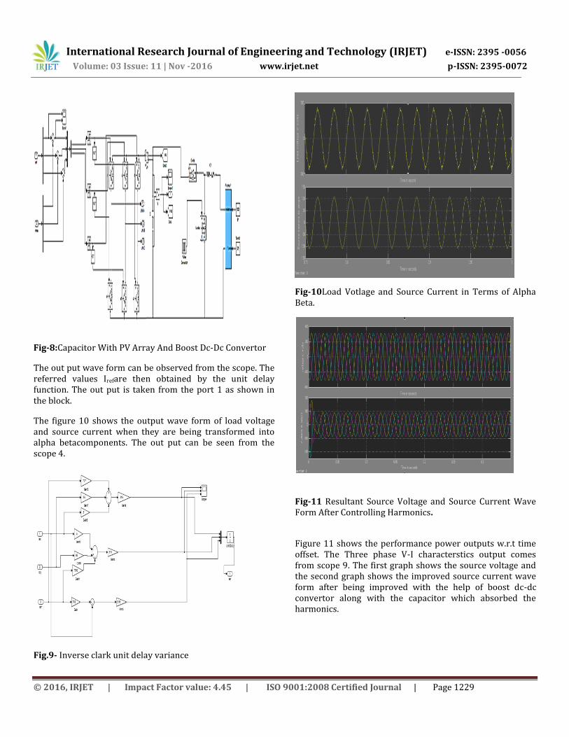
Fig-8:Capacitor With PV Array And Boost Dc-Dc Convertor
The out put wave form can be observed from the scope. The referred values Irefare then obtained by the unit delay function. The out put is taken from the port 1 as shown in the block.
The figure 10 shows the output wave form of load voltage and source current when they are being transformed into alpha betacomponents. The out put can be seen from the scope 4.
Fig.9- Inverse clark unit delay variance
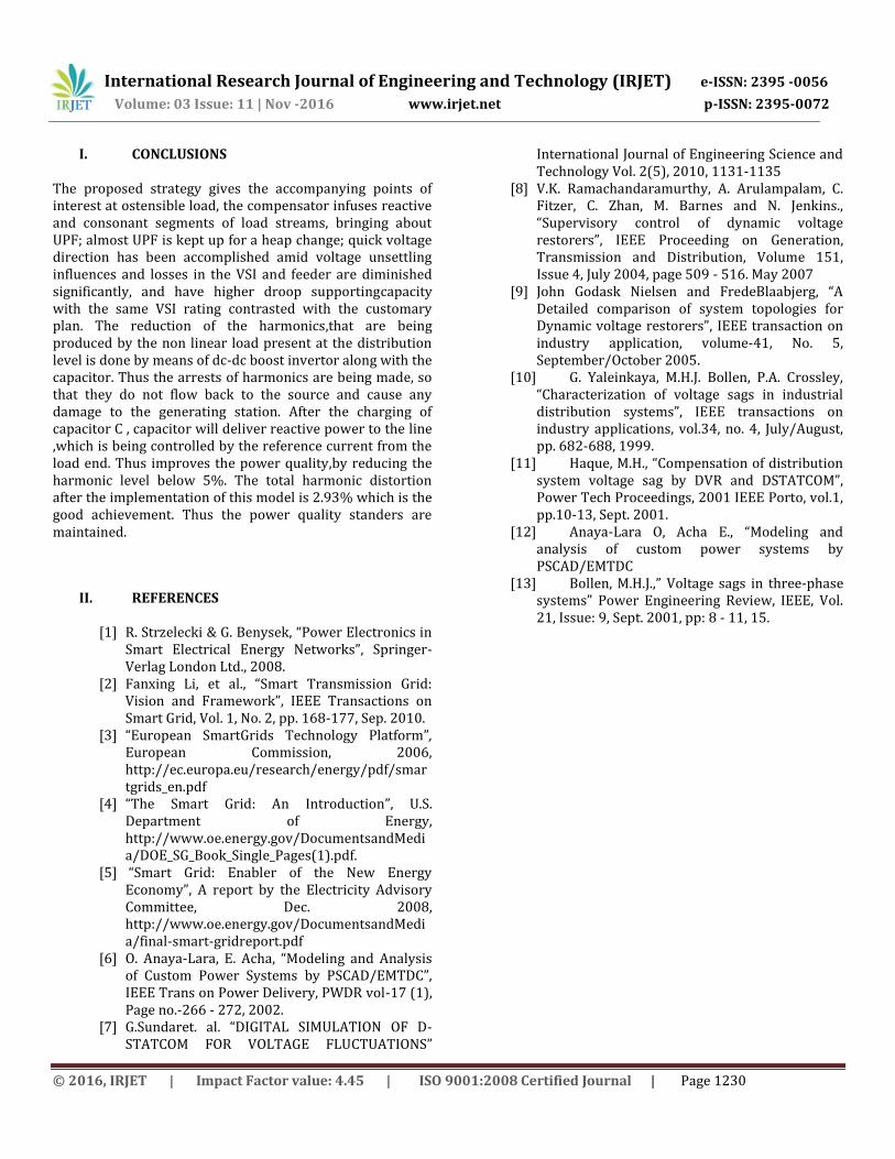
Fig-10Load Votlage and Source Current in Terms of Alpha Beta.
Fig-11 Resultant Source Voltage and Source Current Wave Form After Controlling Harmonics.
Figure 11 shows the performance power outputs w.r.t time offset. The Three phase V-I characterstics output comes from scope 9. The first graph shows the source voltage and the second graph shows the improved source current wave form after being improved with the help of boost dc-dc convertor along with the capacitor which absorbed the harmonics.
International Research Journal of Engineering and Technology (IRJET) e-ISSN: 2395 -0056
Volume: 03 Issue: 11 | Nov -2016 www.irjet.net p-ISSN: 2395-0072
© 2016, IRJET | Impact Factor value: 4.45 | ISO 9001:2008 Certified Journal | Page 1230
I. CONCLUSIONS The proposed strategy gives the accompanying points of interest at ostensible load, the compensator infuses reactive and consonant segments of load streams, bringing about UPF; almost UPF is kept up for a heap change; quick voltage direction has been accomplished amid voltage unsettling influences and losses in the VSI and feeder are diminished significantly, and have higher droop supportingcapacity with the same VSI rating contrasted with the customary plan. The reduction of the harmonics,that are being produced by the non linear load present at the distribution level is done by means of dc-dc boost invertor along with the capacitor. Thus the arrests of harmonics are being made, so that they do not flow back to the source and cause any damage to the generating station. After the charging of capacitor C , capacitor will deliver reactive power to the line ,which is being controlled by the reference current from the load end. Thus improves the power quality,by reducing the harmonic level below 5%. The total harmonic distortion after the implementation of this model is 2.93% which is the good achievement. Thus the power quality standers are maintained.
II. REFERENCES
[1] R. Strzelecki & G. Benysek, “Power Electronics in Smart Electrical Energy Networks”, Springer-Verlag London Ltd., 2008.
[2] Fanxing Li, et al., “Smart Transmission Grid: Vision and Framework”, IEEE Transactions on Smart Grid, Vol. 1, No. 2, pp. 168-177, Sep. 2010.
[3] “European SmartGrids Technology Platform”, European Commission, 2006, http://ec.europa.eu/research/energy/pdf/smartgrids_en.pdf
[4] “The Smart Grid: An Introduction”, U.S. Department of Energy, http://www.oe.energy.gov/DocumentsandMedia/DOE_SG_Book_Single_Pages(1).pdf.
[5] “Smart Grid: Enabler of the New Energy Economy”, A report by the Electricity Advisory Committee, Dec. 2008, http://www.oe.energy.gov/DocumentsandMedia/final-smart-gridreport.pdf
[6] O. Anaya-Lara, E. Acha, “Modeling and Analysis of Custom Power Systems by PSCAD/EMTDC”, IEEE Trans on Power Delivery, PWDR vol-17 (1), Page no.-266 - 272, 2002.
[7] G.Sundaret. al. “DIGITAL SIMULATION OF D-STATCOM FOR VOLTAGE FLUCTUATIONS”
International Journal of Engineering Science and Technology Vol. 2(5), 2010, 1131-1135
[8] V.K. Ramachandaramurthy, A. Arulampalam, C. Fitzer, C. Zhan, M. Barnes and N. Jenkins., “Supervisory control of dynamic voltage restorers”, IEEE Proceeding on Generation, Transmission and Distribution, Volume 151, Issue 4, July 2004, page 509 - 516. May 2007
[9] John Godask Nielsen and FredeBlaabjerg, “A Detailed comparison of system topologies for Dynamic voltage restorers”, IEEE transaction on industry application, volume-41, No. 5, September/October 2005.
[10] G. Yaleinkaya, M.H.J. Bollen, P.A. Crossley, “Characterization of voltage sags in industrial distribution systems”, IEEE transactions on industry applications, vol.34, no. 4, July/August, pp. 682-688, 1999.
[11] Haque, M.H., “Compensation of distribution system voltage sag by DVR and DSTATCOM”, Power Tech Proceedings, 2001 IEEE Porto, vol.1, pp.10-13, Sept. 2001.
[12] Anaya-Lara O, Acha E., “Modeling and analysis of custom power systems by PSCAD/EMTDC
[13] Bollen, M.H.J.,” Voltage sags in three-phase systems” Power Engineering Review, IEEE, Vol. 21, Issue: 9, Sept. 2001, pp: 8 - 11, 15.


![PERFORMANCE OF DVR AND IDVR FOR VOLTAGE ...Power Quality Improvement Using Multi -Level Inverter Based DVR and DSTATCOM Using Neuro -Fuzzy Controller. [3] Power Quality Improvement](https://img.dokumen.tips/doc/110x75/5ed31f7b2c1fe74f476f3361/performance-of-dvr-and-idvr-for-voltage-power-quality-improvement-using-multi.jpg)