Embed Size (px)
Citation preview

Design of an In-situ Spinal Rod Cutter for Orthopaedic Surgeons
by Andre Bodo
A thesis presented to the University of Waterloo
in fulfillment of the thesis requirement for the degree of
Master of Applied Science in
Mechanical and Mechatronics Engineering
Waterloo, Ontario, Canada, 2017 © Andre Bodo 2017

ii
I hereby declare that I am the sole author of this thesis. This is a true copy of the thesis,
including any required final revisions, as accepted by my examiners.
I understand that my thesis may be made electronically available to the public.

iii
Abstract
As spine deformities scoliosis and kyphosis progress in severity, surgical treatment
is often required. Implant rods are attached by bone screws to the spinal vertebrae to
correct these deformities and stabilize the spine. It can be difficult to cut these rods to the
ideal length before implantation and sometimes these rods are too long and must be cut
in-situ. Also, when revision surgery is performed to replace a rod section, in-situ rod
cutting must be performed. The rods are difficult to cut and only manual rod cutting tools
are available. These rod cutters are physically demanding to use and difficult to position
while avoiding any spurious with the exposed spine. There is a clear need for an improved
in-situ rod cutter. Thus, the objective of this thesis is to develop a new and improved
design for an in-situ rod cutter.
Experimental work was done to show that shear cutting and bolt-cutting techniques
produced the most desirable results for cutting spinal rods in-situ. The shear cutting
techniques required slightly less force than bolt cutting techniques and produced a
cleaner rod cut with less deformation. It was found that cutting force increased with the
diameter of the spinal rod, regardless of the rod material. Constraints and criteria were
established to guide the design of a new in-situ rod cutter. It was decided that any attempt
at designing a new in-situ cutter must include a non-manual power source for operation.
Two design alternatives, a shear cutting design and bolt-cutting design were presented
and scored in an engineering design process. A shear cutter design was initially chosen
and work was done to implement the shear cutter design. However, the prototype
fractured in initial testing and the shear cutter design was abandoned. A bolt-cutter design
was then developed and a 3D printed prototype was made to demonstrate the mechanism
involved. Analysis was performed to estimate the mechanical advantage of the
mechanism used to amplify the force applied by a pneumatic cylinder used as the power
source. Further development was required to implement the bolt-cutting design but initial
progress in this design project was achieved. It is recommended that stress analysis,
prototyping and testing be done to move this design towards application in spinal surgery.

iv
Acknowledgements
It is with immense gratitude that I acknowledge the support and guidance of my professor
John B. Medley. Your guidance and wisdom has helped me learn more than I could
imagine. Your advice through my pursuit of higher education was invaluable. Thank you
for everything you’ve done.
Many thanks Dr. Victor Yang for your confidence in me to push boundaries and
accomplish great things. It has been fun and a pleasure working with you.
Thank you Dr. Parham Rasoulinejad, your support to accomplish this thesis was
essential, I am glad we crossed paths and you got involved in this work.
Big thanks to all the staff of the University of Waterloo Engineering Machine Shop, I have
learned a lot from you all, and have enjoyed all the great jokes.
Many thanks to my friend and colleague Mehrdad Irvani, when the going got tough you
were always able to provide perspective, thanks for sharing your experiences in academia
with me.
Thanks to my colleagues and new friends Philippe Meszaros and Evan Wheat. Thanks
for hearing out my crazy ideas, and for the fun times we had when taking a break from
research. Thanks for keeping me sane.
Special thanks to my longtime friends, Henri Spahiu and Vladimir Kirillov. Grazie mille &
Спасибо. You have always been there to provide a great and unique perspective on
matters of great gravity.
Lastly, all the haters… I made it.

v
To my father who taught me the value of education, my mother for supporting all my
endeavors regardless of their nature, and my sister for her kindness.
I love you all very much.
vi
Table of Contents
List of Figures ______________________________________________________ ix
List of Tables ______________________________________________________ xiii
List of Equations ___________________________________________________ xiv
1 Introduction ______________________________________________________ 1
1.1 Problem Statement ______________________________________________ 2
1.2 Motivation _____________________________________________________ 2
1.3 Thesis Outline __________________________________________________ 2
2 Background Literature _____________________________________________ 4
2.1 Clinical Background _____________________________________________ 4
2.2 Spine Anatomy _________________________________________________ 4
2.2.1 Spine Pathology _____________________________________________ 8
2.2.2 Surgical Treatments and Implant Design _________________________ 11
2.2.3 Clinical Problem Statement ___________________________________ 19
2.3 Engineering Background _________________________________________ 19
2.3.1 Rod Material Properties ______________________________________ 19
2.3.2 Existing Cutting Tool Designs __________________________________ 20
2.3.3 Engineering Problem Statement ________________________________ 25
3 Experimental Analysis of Spinal Rod Cutting Forces ___________________ 26
3.1 Manual Experimental Approach ___________________________________ 26
3.1.1 Materials and Methods _______________________________________ 27
3.1.2 Results ___________________________________________________ 30
3.1.3 Discussion ________________________________________________ 35
3.1.4 Indications of Direction _______________________________________ 37
3.2 Automated Experimental Approach _________________________________ 38
3.2.1 Bolt Cutting ________________________________________________ 38
3.2.1.1 Apparatus, Materials and Methods __________________________ 38
3.2.1.2 Results and Analysis _____________________________________ 42
3.2.1.3 Discussion _____________________________________________ 46

vii
3.2.2 Shear Cutting ______________________________________________ 47
3.2.2.1 Materials ______________________________________________ 47
3.2.2.2 Apparatus and Methods ___________________________________ 49
3.2.2.3 Results and Analysis _____________________________________ 51
3.2.2.4 Discussion _____________________________________________ 53
3.2.3 Impact Cutting _____________________________________________ 54
3.2.3.1 Materials and Methods ____________________________________ 54
3.2.3.2 Results ________________________________________________ 57
3.2.3.3 Discussion _____________________________________________ 59
3.2.4 Summary _________________________________________________ 59
4 Initiating the Design ______________________________________________ 61
4.1 Needs Analysis ________________________________________________ 61
4.1.1 When Required _____________________________________________ 61
4.1.2 Problems with the Use of the Current In-Situ Rod Cutters ____________ 63
4.2 Problem Definition ______________________________________________ 64
4.3 Design Constraints _____________________________________________ 64
4.4 Design Criteria ________________________________________________ 69
4.5 The Shear Cutter Design ________________________________________ 71
4.6 Bolt Cutter Design ______________________________________________ 75
4.7 Design Matrix _________________________________________________ 77
5 Design Implementation, with Some Testing and Analysis _______________ 80
5.1 Shear Cutter Design ____________________________________________ 80
5.1.1 Testing of Prototype _________________________________________ 80
5.1.2 Force Analysis _____________________________________________ 82
5.1.3 Discussion ________________________________________________ 85
5.2 Bolt Cutter Design ______________________________________________ 88
5.2.1 Force Analysis _____________________________________________ 88
5.2.2 Prototype Development ______________________________________ 92
5.3 Discussion ____________________________________________________ 95
6 Conclusions and Recommendations for Future Work __________________ 96
Letter of Copyright Permission _________________________________________ 99

viii
References ________________________________________________________ 106

ix
List of Figures
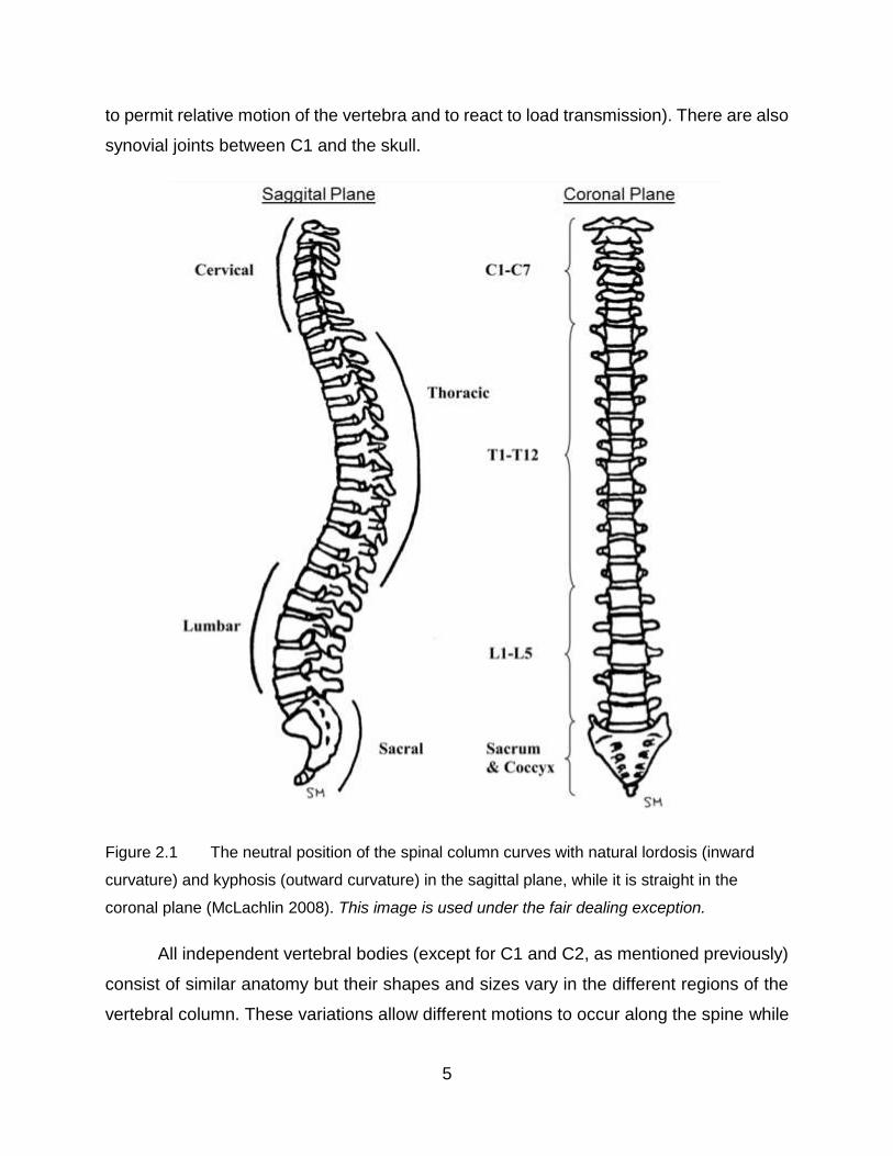
Figure 2.1 The neutral position of the spinal column curves with natural lordosis (inward
curvature) and kyphosis (outward curvature) in the sagittal plane, while it is straight in the
coronal plane (McLachlin 2008). This image is used under the fair dealing exception. _ 5
Figure 2.2 Thoracic vertebra shown illustrating their alignment and connectivity to
each other (McLachlin 2008). This image is used under the fair dealing exception. ___ 6
Figure 2.3 X-ray of scoliotic spine with red arrows showing abnormal curvature of the
spinal column in the sagittal plane (Gkiokas et. al. 2006). This image is used under the
fair dealing exception. __________________________________________________ 8
Figure 2.4 Schematic showing how the Cobb angle α is determined. The Cobb angle is
used to quantify the degree of scoliotic curvature of the spine. ___________________ 9
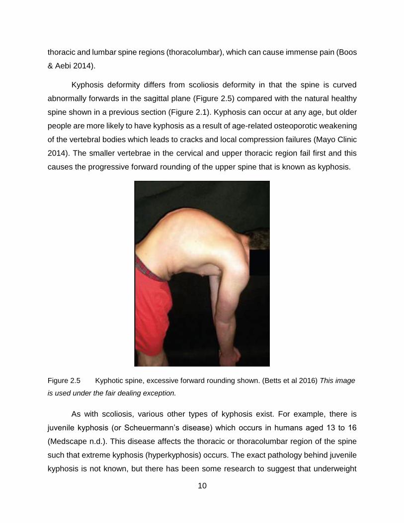
Figure 2.5 Kyphotic spine, excessive forward rounding shown. (Betts et al 2016) This
image is used under the fair dealing exception. ______________________________ 10
Figure 2.6 Pedicle screws driven into the vertebral body (Spine-Health n.d.) This image
is used under the fair dealing exception. ___________________________________ 12
Figure 2.7 Example of a pedicle screw (Zimmer Spine | Sequoia Pedicle Screw Systems
n.d.) This image is used under the fair dealing exception. ______________________ 12
Figure 2.8 Post-surgical x-ray showing spinal instrumentation straightening an adult
spine with scoliosis (Silverjonny 2006) This image is used under the fair dealing
exception. 14
Figure 2.9 Harrington Rods (Medical Apparatus n.d.) This image is used under the
fair dealing exception. _________________________________________________ 15
Figure 2.10 Image of the spinal rods used to correct scoliosis and kyphosis deformities
(Yoshihara 2013) Shown with permission from the Spine Journal ________________ 16
Figure 2.11 Typical modern rod assembly showing multiple screw types and a rod link
(IMTech n.d.) This image is used under the fair dealing exception. _______________ 17
Figure 2.12 Typical rod connector used in revision surgery (DePuy Expedium 4.5
System n.d.) This image is used under the fair dealing exception. _______________ 18
Figure 2.13 Typical modern implant system installed in the spine (Astra Revision Spine
System n.d.) This image is used under the fair dealing exception. _______________ 18

x
Figure 2.14 Bradshaw Medical tabletop rod cutter (Bradshaw Medical OEM Orthopedic
and Spinal Instruments n.d.) This image is used under the fair dealing exception. ___ 21
Figure 2.15 A Holmed racheting hand-held rod cutter. (Holmed) This image is used
under the fair dealing exception. _________________________________________ 22
Figure 2.16 Handheld spinal rod cutters for in-situ cutting ____________________ 24
Figure 2.17 Cutting jaw geometry of in-situ rod cutters. ______________________ 24
Figure 3.1 Mastercraft 24” Heavy Duty Bolt cutter ___________________________ 27
Figure 3.2 Surgical rod cutters used at Victoria Hospital, London, ON ___________ 28
Figure 3.3 The similar blade configuration of the Mastercraft bolt cutters (right) and
the surgical rod cutters (left). ____________________________________________ 28
Figure 3.4 Pipe cutting tool (Canadian Tire Mastercraft 1/8 to 1-1/8-in. Tube Cutter.
(n.d.) This image is used under the fair dealing exception. _____________________ 29
Figure 3.5 Example of cutting disc contact moving along the rod _______________ 30
Figure 3.6 Optical microscopy images of “cut” surfaces using the bolt-cutting technique
32
Figure 3.7 Optical images of cut surfaces using the pipe-cutter technique ________ 34
Figure 3.8 Damaged blades of the bolt cutter after cutting the CoCr rod __________ 36
Figure 3.9 Hit Bolt Cutter (24-inch, Tool No. BC 600-H) made by Toho Koki Co., Ltd.,
Yamatokoriyama, Nara 639-1042, Japan
www.hittools.co.jp/ap/products/en/i/00000000278 This image is used under the fair
dealing exception. ____________________________________________________ 38
Figure 3.10 Centre cut orientation of bolt cutter jaws in the closed position as shown at
www.lawson-his.co.uk/faithfull-faibcj36n-bolt-cutter-jaws-c-p158024 This image is used
under the fair dealing exception. _________________________________________ 39
Figure 3.11 Experimental setup for measuring forces required to cut rods using HIT
bolt cutter 39
Figure 3.12 3D rendering of the custom-made Instron attachment fixture ________ 40
Figure 3.13 Dimensions of bolt cutters used. ______________________________ 43
Figure 3.14 Peak compression force on rod using a bolt-cutter ________________ 44
Figure 3.15 Peak nominal shear stress on rods ____________________________ 45
Figure 3.16 Close up view of damage to the cutting blades on the bolt cutters ____ 47

xi
Figure 3.17 3D rendering of shear cutter _________________________________ 48
Figure 3.18 Lower blades of the shear cutters _____________________________ 48
Figure 3.19 Schematic showing the experimental cutter mounted in the Instron. The
red arrows indicate the direction of motion of the upper jaw. ____________________ 50
Figure 3.20 Typical force-displacement curve _____________________________ 51
Figure 3.21 Typical cut surfaces of CoCr rods, using the shear cutters __________ 52
Figure 3.22 Cutting surface of the upper blade of experimental cutter 2 _________ 53
Figure 3.23 Charpy tester, Satec Systems Inc. (Grove City, Pa) Model SI-1K3 ____ 55
Figure 3.24 Test Specimen ___________________________________________ 55
Figure 3.25 Typical specimens from the Charpy tests. _______________________ 58
Figure 4.1 Depiction of connection sleeve used to connect a replacement rod section to
the remaining section of the existing rod ___________________________________ 62
Figure 4.2 Comparison of contact between cut rod segments and the connection sleeve
63
Figure 4.3 Dimensions of space available for fitting the in-situ cutter into the exposed
spine. 65
Figure 4.4 Ideal surface geometry of spinal rod after it has been cut ____________ 70
Figure 4.5 Holmed rod clamp (www.holmed.net), used to position, rotate and grip onto
spinal rods. Gripper contact width W is in the neighborhood of 10 mm. The rod contacting
this area should be as straight as possible to ensure adequate grip for adjusting the rod
in-situ. This image is used under the fair dealing exception. ____________________ 71
Figure 4.6 Shear-cutting design _________________________________________ 72
Figure 4.7 Schematic showing interior components and how they link together ____ 73
Figure 4.8 Cutting blade geometry shown in the blade closed position. __________ 74
Figure 4.9 3D Rendering of bolt cutter design ______________________________ 75
Figure 4.10 Bolt cutting design shown in its opened state, top view _____________ 76
Figure 4.11 Bolt cutting design shown in its closed state, top view _____________ 76
Figure 4.12 Simplistic description of the internal forces during shear and compression
(bolt) cutting operations. ________________________________________________ 78
Figure 5.1 Front view of experimental cutting mechanism mounted in custom Instron
fixture 80

xii
Figure 5.2 Assembly of experimental cutting mechanism _____________________ 81
Figure 5.3 Cutting sequence of the mechanism ____________________________ 82
Figure 5.4 Free body diagram of the cutting blade in the closed position _________ 83
Figure 5.5 Dimensions necessary to perform analysis of forces shown in Figure 5.4 84
Figure 5.6 Broken cutting blade which failed during experimentation ____________ 86
Figure 5.7 Depiction of how misalignment of the experimental tool blades may have
occurred in the starting position __________________________________________ 86
Figure 5.8 Drawing showing the dimensions necessary to calculate the mechanical
advantage of the bolt cutter in its closed position _____________________________ 88
Figure 5.9 Free body diagram link AB (the cutting blade) in the closed position ____ 89
Figure 5.10 Free body diagram of link BD ________________________________ 90
Figure 5.11 Free body diagram of the piston connecting pin __________________ 91
Figure 5.12 3D rendering of simplifications made to the original bolt cutter design, for
initial prototyping. _____________________________________________________ 92
Figure 5.13 3D printed “proof of motion” prototype in starting position ___________ 94
Figure 5.14 Proof of motion prototype, showing in the position of mid-cut ________ 94
Figure 5.15 Proof of motion prototype shown in final position at the end of the cut. _ 94

xiii
List of Tables
Table 2.1 Material properties of common alloys used to fabricate spinal rods _____ 20
Table 3.1 Summary of rods used _______________________________________ 27
Table 3.2 Rods Used ________________________________________________ 41
Table 3.3 Peak force on handles required to cut the rods ____________________ 42
Table 3.4 Peak forces for the bolt cutting technique with the largest diameter rods of
each material. ________________________________________________________ 45
Table 3.5 Shear cutter dimensions ______________________________________ 48
Table 3.6 Heat treatment schedule developed from Heat Treating Data Book
(SECO/Warwick 2011) _________________________________________________ 49
Table 3.7 Peak forces for the shear cutting technique _______________________ 52
Table 3.8 Impact energy from the Charpy tests ____________________________ 57
Table 4.1 Decision matrix used to determine the optimal design _______________ 77

xiv
List of Equations
Equation 3.1 _________________________________________________________ 43
Equation 3.2 _________________________________________________________ 44
Equation 5.1 _________________________________________________________ 84
Equation 5.2 _________________________________________________________ 84
Equation 5.3 _________________________________________________________ 85
Equation 5.4 _________________________________________________________ 89
Equation 5.5 _________________________________________________________ 90
Equation 5.6 _________________________________________________________ 90
Equation 5.7 _________________________________________________________ 91
Equation 5.8 _________________________________________________________ 91

1
1 Introduction
Modern treatment of spinal deformities such as scoliosis and kyphosis began in the
late 1950’s as Paul Harrington developed the Harrington hook and rod system (Good
2010). The Harrington system used a set of metallic rods and hooks fixed on to the spinal
column bones to correct the deformed curvature of the spine. These spinal rods provide
the stiffness and strength necessary to fuse the spine into a more normal position,
allowing for improved posture, and treatment of medical issues caused by the deformity.
Since the late 1950’s much work has been done on developing the idea of using spinal
rods to correct deformities in the spine. Systems used today involve fixing rods to the
spinal column vertebra using specialized bone screws and tooling to achieve the
correction necessary for improved quality of life.
Typically, high strength metals (cobalt chromium, stainless steel and titanium alloys)
are used to manufacture the spinal rods (Yoshihara 2013). Such materials are necessary
as the rods must be able to support the load of the upper body, since the spinal column
is weakened by the deformity. Of the available rod materials, the cobalt chrome alloy rods
provide the highest amount of stiffness (Noshchenko 2011) and can support these large
loads, providing good correction (Lamerain 2014).
The length of these rods must be correctly sized to each patient’s anatomy. Since
each rod is sized on a case by case basis they must be cut in the operating theatre to the
correct length. Surgeons use rough measurements and experience to determine a correct
rod length for their patient, and then pre-cut the rod to length using a manual table top
rod cutter.
It is sometimes necessary to trim the rod length in-situ once it has been installed into
the patient. This could occur if the rod was cut too long to start with, or if a patient requires
a revision to their original surgery where surgeons replace a section of the rod in-situ.
To cut the rod in-situ, a surgeon has one tool to rely on. This tool is a large in-situ bolt-
cutter which is operated manually by the surgeon. This in-situ rod cutter is positioned,

2
held and operated manually. The high strength material of the rods makes it physically
demanding and difficult to use the in-situ rod cutters, so surgeons must not only cut the
rod but must avoid any damage to the spinal tissues or to the fixation of the rods they are
cutting. The installed rods sit close to the delicate spinal anatomy and it can be precarious
to position the large cutting blades of the tool in the desired location.
1.1 Problem Statement
Orthopedic and neurological surgeons need an improved in-situ rod cutter for cutting
spinal rod implants because the current state of the art in-situ spinal rod cutter is difficult
to use. The current in-situ rod cutter requires significant physical strength to operate and
lacks the agility to easily manipulate it inside the patient.
1.2 Motivation
The current state of the art in-situ rod cutter is difficult to use according to experts Dr.
Victor Yang (Sunnybrook Hospital, Toronto, ON) and Dr. Parham Rasoulinejad (Victoria
Hospital, London, ON). The large forces involved in the operation of the in-situ rod cutter,
and the nimbleness of the cutting blades were a major concern. These issues reduce the
safety of the surgery and, even when overt damage is avoided, there may be problems
with long term pedicle screw fixation after in-situ cutting. There has been some evidence
of detrimental effects that in-situ rod cutting poses to the patient (Aylott 2006).
Additionally, the aforementioned experts are convinced that a better in-situ rod cutter
would improve overall outcomes. Thus, they have made suggestions for improving the in-
situ rod cutting tool which helped to reveal the complexities and limitations which need to
be accounted for in design so that in-situ cutting can be done safely and easily by the
surgeon.
1.3 Thesis Outline
Spinal anatomy and various surgical implants are examined in Chapter 2, so that the
demands and practices of surgery can be understood, but little academic literature was
available on spinal rod cutting because it is considered a mere technical detail of surgery.
Thus, preliminary experimental work was conducted to assess how rod cutters cope with

3
cutting the materials used to fabricate spinal rods. In addition to the bolt cutting technique
employed by the current in-situ rod cutters, shear cutting is investigated as research
suggests such a technique may be capable of cutting with precision (Breitling 1997). A
novel approach of pipe cutting for rods was also investigated, but ultimately this technique
was incompatible with the design problem. The shear cutting and bolt cuttings were
further investigated and the forces needed to cut spinal rods were determined. With the
foundation developed from this experimental work, design constraints and criteria could
be established and the engineering design processes was applied to develop a new
design for an in-situ spinal rod cutter.
Two design alternatives that were judged to have satisfied the constraints (or bounds)
of the design problem were then evaluated according to the established criteria in Chapter
5. The optimum design was chosen and a prototype was fabricated. This prototype
revealed problems with the design, so development work was initiated on the other
alternative design. Time constraints prevented further development but the design
foundations which were established and the final iteration of the design process did allow
a number of conclusions to be presented in Chapter 6 along with some ideas for further
work and progress.

4
2 Background Literature
2.1 Clinical Background
Surgical procedures involving the spine must pay close attention to its complex
anatomy because any implants, such as spinal rods, must essentially fit in and be fixed
within the spinal structure. Deformities of the spinal curvature present a pathology that
can affect the function of the spine. Some of these deformities are caused by underlying
disease, but others are classified as idiopathic (having unknown causes). The two most
common and well recognized spinal deformities are kyphosis and scoliosis. Both of these
deformities can be treated for using a variety of surgical and non-surgical techniques.
Spinal implants are typically used to treat severe cases of scoliosis and kyphosis, where
the deformity poses a threat or hindrance to quality of life. Implants are installed using
surgical tools which are designed to work within the constraints of spinal surgery. Thus,
spinal anatomy and curvature pathology are important consideration in tool design. For
example, tools such as in situ spinal implant rod cutters must fit and function within a
confined space near the spinal column.
2.2 Spine Anatomy
The primary functions of the spine are to transmit loads from connected structures to
the pelvis, provide support and facilitate mobility to the body (Boos & Aebi 2008) and to
protect the spinal cord. The spine is grouped into four distinct regions of function: cervical,
thoracic, lumbar and sacral. As explained by Patel et al. (2014), the overall structure
consists of 24 independent vertebral bodies, each separated by intervertebral discs.
The cervical spine consists of seven independent vertebral bodies while the thoracic
has twelve, the lumbar has five and the sacral region has one large body consisting of
five fused vertebral bodies along with a small flexible tailbone (coccyx) section. (Figure
2.1). The top two vertebrae, atlas (C1) and axis (C2) do not have a disc between them
(Patel et al 2014). Instead, there are synovial joints that permit guided relative sliding of
the vertebra and load transmission (whereas the discs only have their own deformation
5
to permit relative motion of the vertebra and to react to load transmission). There are also
synovial joints between C1 and the skull.
Figure 2.1 The neutral position of the spinal column curves with natural lordosis (inward
curvature) and kyphosis (outward curvature) in the sagittal plane, while it is straight in the
coronal plane (McLachlin 2008). This image is used under the fair dealing exception.
All independent vertebral bodies (except for C1 and C2, as mentioned previously)
consist of similar anatomy but their shapes and sizes vary in the different regions of the
vertebral column. These variations allow different motions to occur along the spine while

6
transmitting loads are as explained by Patel. In general, the vertebral bodies become
progressively larger from the upper to the lower regions of the spine. Cervical and thoracic
vertebrae transmit vertical loads through their discs and through the articulation of
connecting synovial joints (called facet joints). These synovial facet joints also transmit
lateral loads (almost exclusively in the lumbar spine) and thus because of their distance
from the neutral axis of the spine they transmit torsional moments (Figure 2.2). The facet
joints vary in orientation when viewed from the sagittal plane to achieve this complex load
carriage. The more horizontally oriented facet joints in the upper spine enable a greater
degree of rotational motion than the more vertically oriented facet joints in the lower spine.
Accordingly, the highest degree of rotational motion in the spine occurs in the cervical
region (Patel et al 2014).
Figure 2.2 Thoracic vertebra shown illustrating their alignment and connectivity to each
other (McLachlin 2008). This image is used under the fair dealing exception.
As explained in Boos & Aebi, the vertebral material composition consists of a
compliant inner trabecular bone, which is shielded by a dense stiffer cortical bone shell.
With the exception of the space between C1 and C2, intervertebral discs exist between
each vertebral body. These discs, composed of a fluid-filled nucleus and circumferential

7
collagen layers provides shock absorption loading reducing peak stresses on the vertebra
caused by impact loading. The discs transmit compressive, bending and torsion loading
along the spinal column. If the discs’ degenerate, load distribution is no longer uniform
across the discs. This causes abnormal local deformation, high local stresses and
compression of adjacent nerves or nerves within the vertebral bone (Boos & Aebi 2014).
Force transmission and motion guidance within the spine structure is also
dependent on the ligaments that connect vertebral bodies together (Patel et al. 2014).
Various intersegmental ligaments are affixed to multiple vertebrae providing resistance to
flexion motion of the spinal. These ligaments connect adjoining spinous processes
together, and assist in maintaining upright posture. Also, the synovial facet joints are
surrounded by the capsular ligaments which prevent distraction and guide motion.
In addition to the ligaments, the musculature of the back insert into the vertebrae
of the spinal column. The spinal column plays a significant role in supporting anatomical
extremities, helping to stabilize the body and transmit loads (Boos & Aebi 2014). Besides
connection to the extremities, the muscles form a thick protective soft tissue barrier on
top of the spinal column.
The fundamental motion segment of the spine is the vertebra-disc-vertebra unit
that allows for simultaneous flexion, extension, bending and rotation. However, as
previously mentioned, vertebrae C1 and C2 and the skull (sometimes referred to as C0)
have synovial joints between them rather than discs. Their relative motion is responsible
for the majority of rotational motion of the spine. This motion segment rotates axially
approximately 5 - 8 times the amount of rotation when compared to the other cervical
motion segments (Patel et al 2014). The entire cervical region of the spine is the most
mobile, with twice as much flexion/extension as the lumbar region and five times as much
as the thoracic region (Patel et al 2014). Lateral bending occurs in all motion segments
and is quite similar, in the range of 5 – 10 degrees. Patel also said that overall the majority
of spinal motion is flexion and extension with a high degree of rotation occurring at the
atlas-axis motion segment. The spinal column experiences several types of loading: axial
compression, shear, bending and torsion. During lifting activities, the lumbar spine can
experience very high loads (5000 – 8000N) which approach the failure loads that a single

8
vertebra can handle (Boos & Aebi 2014), with the most likely location of failure at the
vertebral endplate (Grant et al. 2002).
2.2.1 Spine Pathology
Scoliosis and kyphosis are two significant spinal deformity diseases. If severe and/or
progressive enough, they can be corrected using rod-type implants. Scoliosis is abnormal
curvature of the spine occurring in the coronal plane (Figure 2.3). In order to be
considered a “scoliotic” deformity, the coronal spinal column curvature as measured by
the Cobb angle (Figure 2.4) must exceed 10° (Boos & Aebi 2014). This coronal plane
curvature is also combined with vertebral body rotation about the long axis of the spine
(Boos & Aebi 2014).
Figure 2.3 X-ray of scoliotic spine with red arrows showing abnormal curvature of the spinal
column in the sagittal plane (Gkiokas et. al. 2006). This image is used under the fair dealing
exception.

9
Figure 2.4 Schematic showing how the Cobb angle α is determined. The Cobb angle is
used to quantify the degree of scoliotic curvature of the spine.
Scoliotic deformities can be classified into four different types: idiopathic,
neuromuscular, congenital, and degenerative (Boos & Aebi 2014). Idiopathic scoliosis is
the most common in adolescents between the ages of 10 – 18 years (Spine Centre n.d.),
and typically occurs in the thoracic spine region. In some cases, it may be caused by an
imbalance of growth in both the anterior and posterior sides of the vertebral bodies
possibly with genetics and connective tissue diseases being involved (Guo et al 2003).
Large amounts of vertebral rotation and curvature in the coronal plane can cause nerve
impingement and pain, as well as rib cage compression of internal organs.
Neuromuscular scoliosis is associated with an existing underlying nerve or
muscular condition some of which include: tumors, spinal cord injury and cerebral palsy
(Boston Children’s Hospital n.d.). These diseases cause the muscular system to become
weak and therefore the spine cannot be supported, causing curvatures. Congenital
scoliosis is the presence of coronal plane curvature caused by abnormal structural
vertebral defects that are present at birth (AAOS 2010).
Degenerative scoliosis is caused by intervertebral disc degeneration. A
progressive structural degeneration of the disc leads to asymmetric loading on the spinal
column which ultimately leads to a progressive deformity of the spine, particularly in the
10
thoracic and lumbar spine regions (thoracolumbar), which can cause immense pain (Boos
& Aebi 2014).
Kyphosis deformity differs from scoliosis deformity in that the spine is curved
abnormally forwards in the sagittal plane (Figure 2.5) compared with the natural healthy
spine shown in a previous section (Figure 2.1). Kyphosis can occur at any age, but older
people are more likely to have kyphosis as a result of age-related osteoporotic weakening
of the vertebral bodies which leads to cracks and local compression failures (Mayo Clinic
2014). The smaller vertebrae in the cervical and upper thoracic region fail first and this
causes the progressive forward rounding of the upper spine that is known as kyphosis.
Figure 2.5 Kyphotic spine, excessive forward rounding shown. (Betts et al 2016) This image
is used under the fair dealing exception.
As with scoliosis, various other types of kyphosis exist. For example, there is
juvenile kyphosis (or Scheuermann’s disease) which occurs in humans aged 13 to 16
(Medscape n.d.). This disease affects the thoracic or thoracolumbar region of the spine
such that extreme kyphosis (hyperkyphosis) occurs. The exact pathology behind juvenile
kyphosis is not known, but there has been some research to suggest that underweight

11
and tall children are at higher risk (Oded et al 2004). Another type of kyphosis is
congenital kyphosis which is an abnormal forwards curvature of the spine present at birth.
This type of kyphosis is uncommon but can be quite catastrophic and may result in the
spinal cord being crushed. For this particular type of kyphosis, surgical treatments with
implants are always necessary (Winter 1977).
When looking for similarities in the development of abnormal spinal curvatures
(scoliosis and kyphosis), it is important to note that the natural ageing process has a
degenerative effect on the spinal column. In comparison to the other musculoskeletal
tissues in the body the spinal column degenerates much sooner in life (Boos & Aebi
2014). Intervertebral discs, vertebrae endplate cartilage, and facet joints degenerate with
time along with a decrease in blood supply which affects delivery of nutrition. This
degeneration of the spine results in a decrease in spine articulation and the ability of the
spine to support and stabilize the body. Vertebral body structure strength, musculature
and ligaments also degenerate though a variety of mechanisms, often accelerated by
aging. Consequently, both scoliosis and kyphosis can often be attributed to aging.
2.2.2 Surgical Treatments and Implant Design
Surgical treatment of abnormal spinal curvature involves the installation of spinal
rods to mechanically realign the spinal column. These metallic rods span the least the
length of the deformity and are attached to the spine using screws which are driven into
the pedicles of each vertebral body (Figure 2.6).
12
Figure 2.6 Pedicle screws driven into the vertebral body (Spine-Health n.d.) This image is
used under the fair dealing exception.
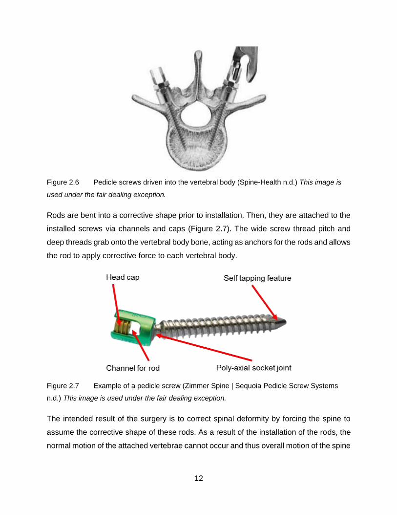
Rods are bent into a corrective shape prior to installation. Then, they are attached to the
installed screws via channels and caps (Figure 2.7). The wide screw thread pitch and
deep threads grab onto the vertebral body bone, acting as anchors for the rods and allows
the rod to apply corrective force to each vertebral body.
Figure 2.7 Example of a pedicle screw (Zimmer Spine | Sequoia Pedicle Screw Systems
n.d.) This image is used under the fair dealing exception.
The intended result of the surgery is to correct spinal deformity by forcing the spine to
assume the corrective shape of these rods. As a result of the installation of the rods, the
normal motion of the attached vertebrae cannot occur and thus overall motion of the spine

13
is reduced. Although this is somewhat undesirable, the alternative progression of the
abnormal curvature is more undesirable.
Most surgeries for the abnormal spinal curvatures (resulting from scoliosis and
kyphosis) involve cutting the back skin and muscles open along the area of intended
fusion and performing a posterior release by resecting the spinal ligaments and facet
capsules (Patel et al 2014). This posterior release reduces resistance to alignment and
clears the spine for the implant placement. The screws are placed into pedicles (Figure
2.11) and the rods are bent into the correct shape and placed in the screws. As the rods
are placed, the spine becomes aligned to the corrected position. The implant rods and
anchoring screws immobilize the spine over their region of placement and carry the loads
imposed during subsequent patient activities of normal living. There are also minimally
invasive surgery (MIS) techniques that use such instrumentation but the screws are
placed percutaneously so long open cuts along the back are not required (Ozgur et al
2009). A long rod is then placed percutaneously through a small stab wound (Foley et al.
2001). Achieving the required correction can be challenging but MIS reduces overall
trauma to the patient and can still correct spinal curvature (Figure 2.8). In any case, long
rods are still used.

14
Figure 2.8 Post-surgical x-ray showing spinal instrumentation straightening an adult spine
with scoliosis (Silverjonny 2006) This image is used under the fair dealing exception.
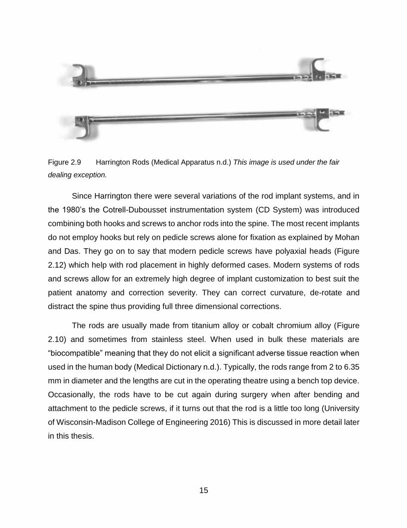
Modern spinal implants owe much to Paul Harrington who designed the first
internally stabilizing spinal system consisting of a combination hooks and rods in the
1950’s (Figure 2.9). Mohan and Das (2003) explain that prior to Harrington rods, spine
vertebrae were fused without implants and held in place with external casts which was
both ineffective and inconvenient for patients. However, there were a few successful
attempts at wiring the spinous processes together. Even though Harrington rods were a
major improvement over the old ways, patients often lost natural curvature in the lumbar
spine region with Harrington rods according to Mohan and Das.
15
Figure 2.9 Harrington Rods (Medical Apparatus n.d.) This image is used under the fair
dealing exception.
Since Harrington there were several variations of the rod implant systems, and in
the 1980’s the Cotrell-Dubousset instrumentation system (CD System) was introduced
combining both hooks and screws to anchor rods into the spine. The most recent implants
do not employ hooks but rely on pedicle screws alone for fixation as explained by Mohan
and Das. They go on to say that modern pedicle screws have polyaxial heads (Figure
2.12) which help with rod placement in highly deformed cases. Modern systems of rods
and screws allow for an extremely high degree of implant customization to best suit the
patient anatomy and correction severity. They can correct curvature, de-rotate and
distract the spine thus providing full three dimensional corrections.
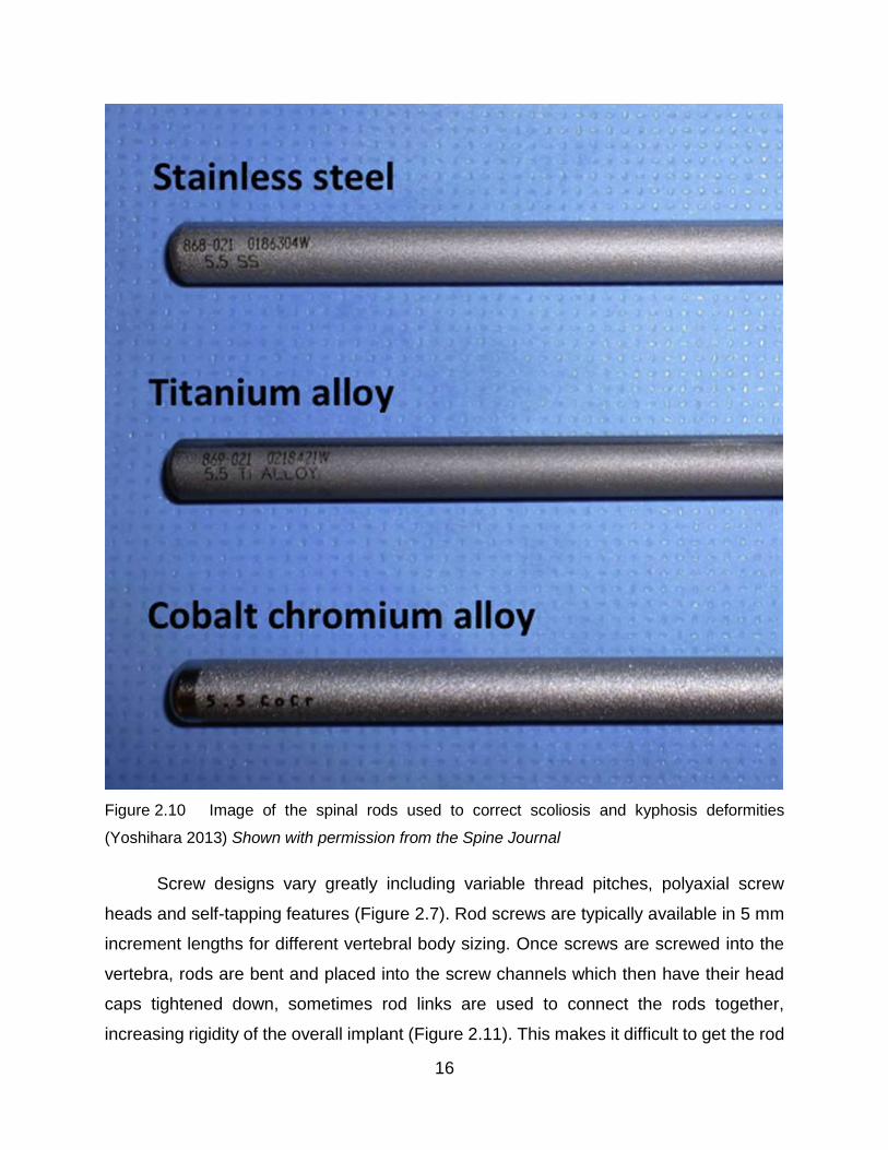
The rods are usually made from titanium alloy or cobalt chromium alloy (Figure
2.10) and sometimes from stainless steel. When used in bulk these materials are
“biocompatible” meaning that they do not elicit a significant adverse tissue reaction when
used in the human body (Medical Dictionary n.d.). Typically, the rods range from 2 to 6.35
mm in diameter and the lengths are cut in the operating theatre using a bench top device.
Occasionally, the rods have to be cut again during surgery when after bending and
attachment to the pedicle screws, if it turns out that the rod is a little too long (University
of Wisconsin-Madison College of Engineering 2016) This is discussed in more detail later
in this thesis.
16
Figure 2.10 Image of the spinal rods used to correct scoliosis and kyphosis deformities
(Yoshihara 2013) Shown with permission from the Spine Journal
Screw designs vary greatly including variable thread pitches, polyaxial screw
heads and self-tapping features (Figure 2.7). Rod screws are typically available in 5 mm
increment lengths for different vertebral body sizing. Once screws are screwed into the
vertebra, rods are bent and placed into the screw channels which then have their head
caps tightened down, sometimes rod links are used to connect the rods together,
increasing rigidity of the overall implant (Figure 2.11). This makes it difficult to get the rod

17
just the right length and occasionally it turns out to be too long, as previously noted, and
must be cut in situ.
Figure 2.11 Typical modern rod assembly showing multiple screw types and a rod link
(IMTech n.d.) This image is used under the fair dealing exception.
Sometimes a second surgery is performed and the original rod is partially replaced
or extended in length. This is the case with revision surgeries to replace stiff sections of
the rod which have pulled the pedicle screws out from the bone (Hoppe 2016). When
extension is required special connectors are used (Figure 2.12) These connectors vary
in style, but they all join a new section of spinal rod, to an existing section
18
Figure 2.12 Typical rod connector used in revision surgery (DePuy Expedium 4.5 System
n.d.) This image is used under the fair dealing exception.
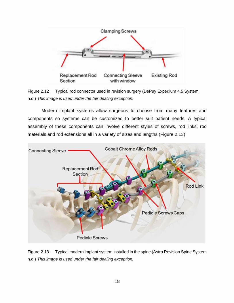
Modern implant systems allow surgeons to choose from many features and
components so systems can be customized to better suit patient needs. A typical
assembly of these components can involve different styles of screws, rod links, rod
materials and rod extensions all in a variety of sizes and lengths (Figure 2.13)
Figure 2.13 Typical modern implant system installed in the spine (Astra Revision Spine System
n.d.) This image is used under the fair dealing exception.
19
2.2.3 Clinical Problem Statement
Having discussed the physiology, treatment and instrumentation of the spine, the
complexities of designing an in-situ rod cutter can be better appreciated. The complex
anatomy of the spine is difficult for surgeons to navigate, as many anatomical components
play a vital role in the stability and quality of life of their patients. Spinal rods must be
strong enough to be able to not only straighten the spine from deformity, but also support
loading of the muscles attached to the spinal anatomy. It is difficult to manipulate and size
these rods to straighten the spine because of the complex curvatures in the spine. When
fully implanted, it becomes quite difficult to gain access around the rod due to the limited
space available, thus care must be taken to not damage the surrounding tissues or
traumatize the spine when further manipulating the rod in-situ. A lot of possibilities exist
for implanting rods of different size, material and accompanying implants, which also
restrict the amount of maneuverability in the exposed spine. Because of all these
variables, an in-situ rod cutter design has these aforementioned clinical problems to
address.
2.3 Engineering Background
Examination of the types of rod materials and the design of currently used rod
cutting instruments helps to establish the engineering characteristics of the challenges a
clinician faces.
2.3.1 Rod Material Properties
Currently, cobalt chrome (CoCr), titanium (Ti) and austenitic stainless steel (SS)
alloys are used in the manufacture of surgical spinal rods. Although having
aforementioned in Section 1.1 that cobalt chrome alloy rods are the most commonly used
rods, there has been growing interest in Ti rods for their compatibility with magnetic
resonance imaging machines (Yoshihara 2013). Each rod material must be fabricated in
accordance with the material properties specified by the American Society for Testing and
Materials (ASTM) in order to be considered adequate for implantation (Table 2.1).

20
Table 2.1 Material properties of common alloys used to fabricate spinal rods
Rod Alloy Designation ASTM Specification Ultimate Tensile
Strength (MPa)
Stainless Steel 316L F139-12 860
Cobalt Chrome Co-28Cr-6Mo F75-12 960
Titanium Ti-6Al-4V F136-13 825
These ASTM standards only provide the minimum requirements for medical implants, and
manufacturers are likely to modify the mechanical properties of these allows in a
proprietary manner. Thus, the mechanical properties of the spinal rods must be
determined with extensive materials testing, which was not performed in this work since
the design aspects did not require. It was noted that the minimum requirement for ultimate
tensile strengths are somewhat similar, suggesting all spinal rods alloys are designed
meet a similar minimum strength regardless of the alloy used.
2.3.2 Existing Cutting Tool Designs
The design and performance of spinal rod cutting tools are not described much in
academic literature. The complexities and nuances of spinal rod cutters are primarily left
up to industry. Rod cutting systems can be classified into either a handheld or tabletop.
Both handheld and tabletop variations provide a means of cutting rods of varying
diameters and materials through some form of mechanism. Currently, all spinal rod
cutters apply either shear or compression forces through blades to perform the required
task. Abrasive cutting, melting, vaporizing or chemical methods are not used to cut rods.
Additionally, all rod cutting is performed manually by the surgeon in the operating room.
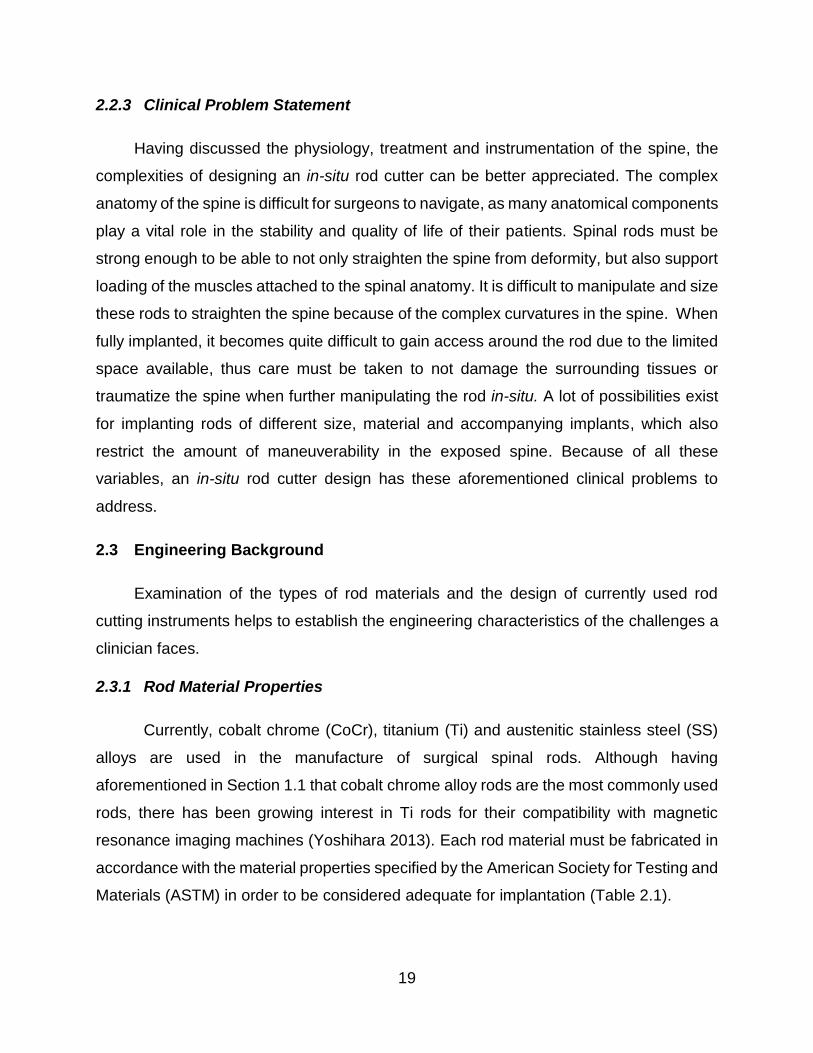
Tabletop rod cutters (Figure 2.14) are typically levers where the load and fulcrum
points are close together and the effort force is much farther away. Rods are placed
through aligned bore holes in two components that have diameters just larger than the
rod diameter and have centres at a small radial distance from the fulcrum axis. The lever
arm is attached to one component and acts to displace the bore hole that holds the rod
thus applying a shear force to cut it (Lenox 1999). The entire tool is mounted on a tabletop
21
such that the lower lever arm is supported by a table and bodyweight can be used to the
operator’s advantage when pressing down on the top lever. The use of the tabletop rod
cutter is restricted to the ex-situ cutting of spinal rods. As previously described, this means
that the rod length must be determined based on the measurements, experience and
judgement of a surgeon, before implantation and before rod bending is performed. If a
surgeon needs to revise their estimate of the rod length, they must do so before any
significant bending of the rod occurs, because the rod will not feed through the tabletop
cutter if it is not straight.
Figure 2.14 Bradshaw Medical tabletop rod cutter (Bradshaw Medical OEM Orthopedic and
Spinal Instruments n.d.) This image is used under the fair dealing exception.
22
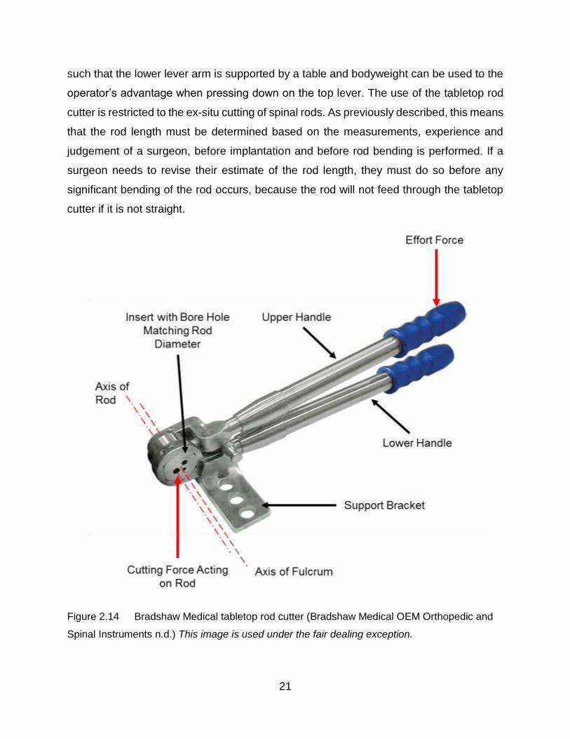
As an alternative to tabletop rod cutters, handheld rod cutting tools exist. Within
the range of these handheld bolt cutters, there are two fundamental design variations.
The first variation is similar to the tabletop design, but in miniaturized format. Neither lever
arm is designed to be supported by a table, so they are both are operated by the surgeon.
A modern version of this involves a ratcheting mechanism (Figure 2.15) to assist in the
cutting process by keeping the displacement associated with the effort force on the rod
thus giving creep deformation time to occur. The surgeon then “pumps” the levers re-
asserting the maximum effort force. One of the levers is held fixed in space relative to the
other, while the lever attached to the ratcheting mechanism is displaced by the effort
force. When the effort force is released, the ratcheting lever arm is sprung back to its
original position by a small leaf spring.
Figure 2.15 A Holmed racheting hand-held rod cutter. (Holmed n.d.) This image is used
under the fair dealing exception.

23
This variation of hand held rod cannot not be used in-situ as it requires that the
spinal rod is passed though the cutting cylinder through hole. Clearances between
implanted rods and the surrounding anatomy do not allow for room to place this handheld
cutter into the dissected back.
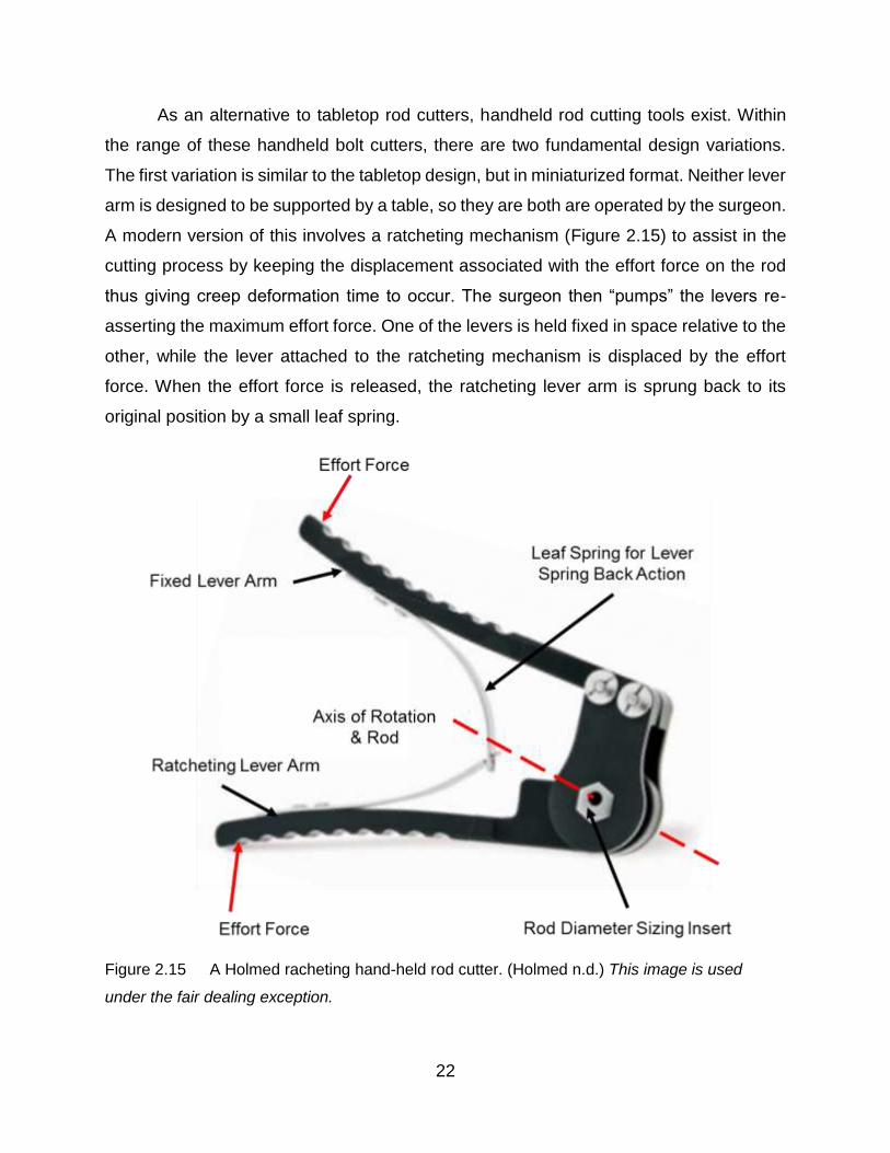
The second design variation is essentially identical to the previously described
bolt-cutter (in Chapter 3). The effort force is applied to the lever arms to close a jaw lever
which cuts through the spinal rod by applying a large compressive stress (Figure 4.6).
There are two sets of levers that act together to multiply the mechanical advantage of
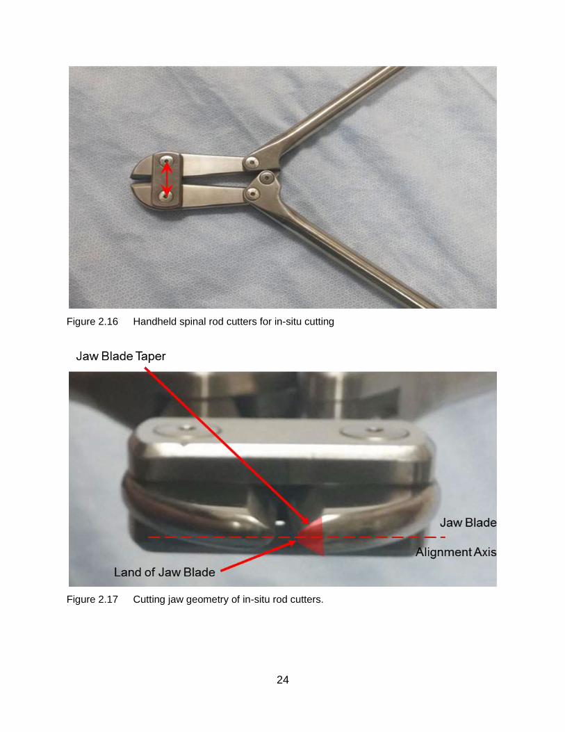
each lever together. As discussed in Chapter 3, the jaw blades have small lands on their
cutting face, with a taper on either side to “wedge” the blade into the rod and separate
the material (Figure 2.17). These lands and jaws are aligned with each other and thus
apply direct compressive stress rather than shear stress. This variation of handheld rod
cutters can be used for in-situ cutting, but the surgical incision must be spread enough to
allow the jaws to be inserted around the implanted spinal rod. This design is the only
current solution for in-situ rod cutting and it has significant usage problems, as described
in the next section. Consequently, the surgeons try as best they can to cut rods to the
required length before implantation. However, there are numerous occasions on which
in-situ rod cutting cannot be avoided, in particular during revision surgeries.
24
Figure 2.16 Handheld spinal rod cutters for in-situ cutting
Figure 2.17 Cutting jaw geometry of in-situ rod cutters.

25
2.3.3 Engineering Problem Statement
Regardless of alloy, all spinal rods are designed to meet a similar minimum
medical specification as specified by the ASTM. These material properties are selected
to provide the support necessary for correcting and loading the spine. While work has
been done on determining bending stiffness (Guidici 2017) and fatigue characteristics of
these rods, little exists on the shearing and bolt cutting techniques which are used by
these tools. The current tools for cutting rods employ long levers, using mechanical
advantage to provide the required forces at their cutting zones. These tools are bulky and
heavy, lacking nimbleness. All of them are manually operated, and only one style of
design is capable of in-situ rod cutting. There is not a lot of literature available on how
these tools operate, or the forces involved with cutting these spinal rods, so before any
design of a new in-situ rod cutter occurs, work must be done to better understand these
challenges and nuances of cutting spinal rods.

26
3 Experimental Analysis of Spinal Rod Cutting Forces
The experimental work presented here provides an idea of the nuances of rod cutting,
and develops an understanding of the requirements for designing a new cutting tool. A
bolt cutting technique was investigated that was very similar to the existing in-situ rod
cutting technique. A shear cutting technique was chosen for exploration as the author
took inspiration from existing shear cutting devices for pipes, while an impact cutting
technique was investigated to determine if cutting with an impact force could reduce the
force required to cut a rod. These three techniques were selected as they were thought
of to be the most feasible options for cutting spinal rods in-situ. Other techniques, such
as abrasive cutting, were rejected because the resulting debris would have to be kept
away from the patient and this would be very difficult. The following experiments shed
light on the feasibility of these cutting techniques as well as the forces required to cut
spinal rods. The observations and experimental results are also used to help form
constraints and criteria for the design process.
3.1 Manual Experimental Approach
Initially, two quite different techniques for cutting rods were chosen for examination.
A bolt-cutting technique was selected since handheld bolt cutting tools are already used
in the operating theatre. A pipe cutting technique developed for copper tube cutting was
also selected because it provided a more gradual, lower force alternative to direct
shearing. Surgically retrieved rods of varying materials and size were cut using both
techniques and examinations of the resulting cut rod ends were performed. Since it was
costly to purchase new rods, this experiment proceeded with a representative selection
of retrieved rods of various materials and diameters. Most of the rods used in the
experimentation were left over pieces from a primary surgery. The two cutting techniques
were qualitatively assessed by examining the cut surfaces.

27
3.1.1 Materials and Methods
Four groups of rods were used (Table 3.1). They were made from medical grade
alloys and, as previously mentioned, they were either retrieved components or extra
sections left over from primary surgeries performed at Victoria Hospital (London, ON).
Table 3.1 Summary of rods used
Rod Material Symbol Diameter [mm]
Stainless Steel (316L) SS 4.50
Titanium (Ti 6Al 4V) Ti 3.50
Nickel-Cobalt (MP 35N) MP35N 4.75
Cobalt-Chromium (Co 28Cr 6Mo) CoCr 6.35
The bolt-cutting technique is manually performed using a hand-held bolt cutter
(Mastercraft 24” Heavy Duty Bolt Cutter, Canadian Tire) with a cutting head that had been
made from a proprietary chromium-vanadium steel alloy with a specified hardness of 55
Rockwell C (Figure 3.1). This bolt cutter was very similar to those used in surgery (Figure
3.2) with about the same jaw geometry and hardness of the cutting edges but the
materials were not surgical grade alloys and would tend to corrode upon repeated
autoclave sterilization.
Figure 3.1 Mastercraft 24” Heavy Duty Bolt cutter
28
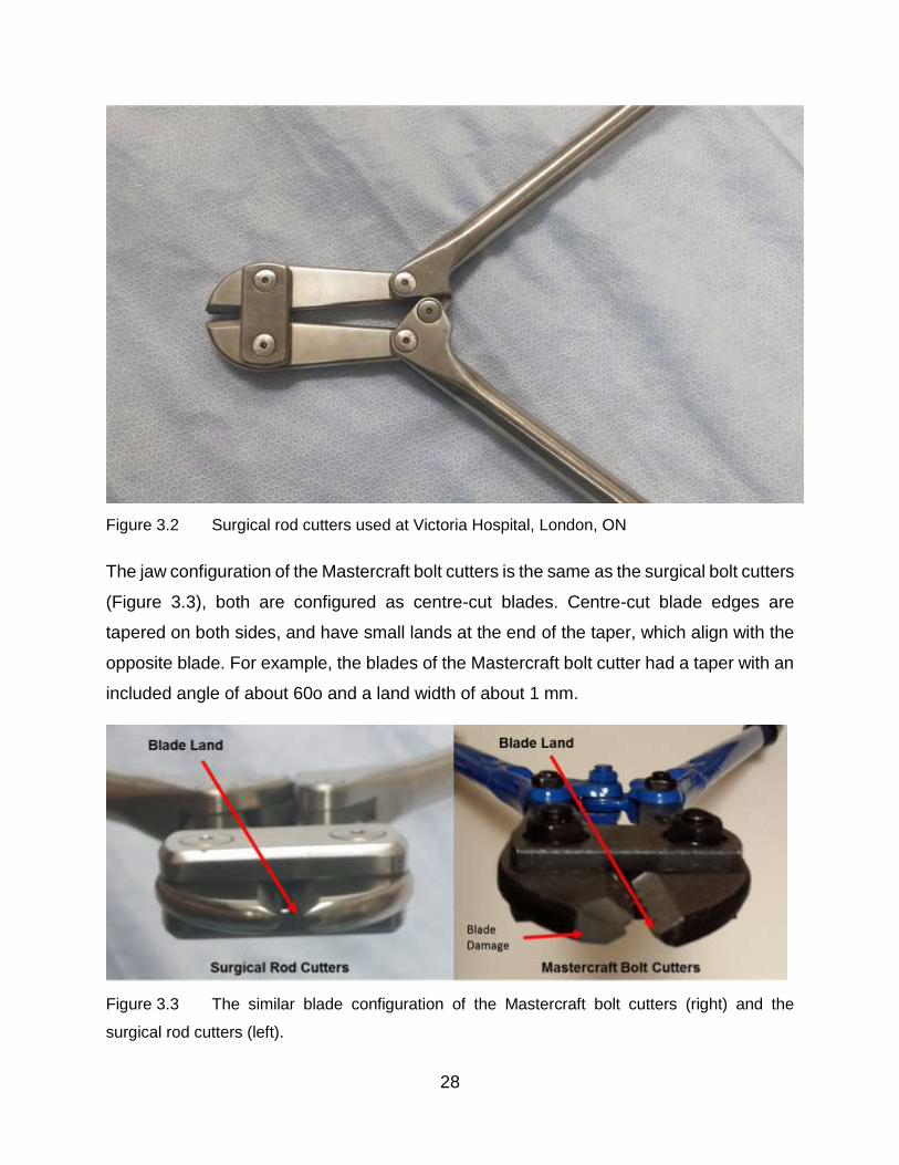
Figure 3.2 Surgical rod cutters used at Victoria Hospital, London, ON
The jaw configuration of the Mastercraft bolt cutters is the same as the surgical bolt cutters
(Figure 3.3), both are configured as centre-cut blades. Centre-cut blade edges are
tapered on both sides, and have small lands at the end of the taper, which align with the
opposite blade. For example, the blades of the Mastercraft bolt cutter had a taper with an
included angle of about 60o and a land width of about 1 mm.
Figure 3.3 The similar blade configuration of the Mastercraft bolt cutters (right) and the
surgical rod cutters (left).

29
The Mastercraft bolt cutter was chosen for this preliminary experiment because it
was cheap and readily available. Rods were placed between the cutting jaws of the bolt
cutter, held in place using a minimal clamping force, and the lever arms were vertically
oriented to mimic the position used in surgery. The lever arms were closed manually with
a swift and constant motion, using bicep flexion and the rod was sheared.
The quite different pipe-cutting technique was also manually performed using a
commercially available product (Mastercraft 1/8 to 1-1/8-in. Tube Cutter) that was
purchased from Canadian Tire. It had a c-clamp shape with two support rollers that were
squeezed towards a cutting roller using the lead screw mechanism (Figure 3.4).
Figure 3.4 Pipe cutting tool (Canadian Tire Mastercraft 1/8 to 1-1/8-in. Tube Cutter. (n.d.)
This image is used under the fair dealing exception.
The cutting disc material was a tool steel but the detailed specifications were not
known. The pipe cutter was loaded with a retrieved rod, and the lead screw was rotated
until the rod contacted the upper cutting disc. The entire pipe cutter was rotated around
180 degrees. The cutter was then reversed 360 degrees to ensure that the scoring of
cutting wheel was aligned. Failure to do this resulted in the cutting disc contact moving
along the rod (Figure 3.5), thus creating a misaligned screw shaped scoring which

30
prevented efficient cutting. The lead screw was then tightened and the pipe cutter was
again rotated. The tightening and rotation were repeated until the rod was cut.
Figure 3.5 Example of cutting disc contact moving along the rod
Each rod was cut three times using both of the techniques described. Pictures of the
resulting cut rod surfaces are taken using a stereo microscope. The deformation types
present during the cutting operations were characterized and then measured using a free
open source software package (ImageJ downloaded from https://imagej.nih.gov/ij/)
3.1.2 Results
Examination of the cut surfaces from the bolt-cutting technique showed two
different types of deformation occur during the shearing process. An outer region of slow
plastic deformation (SPD) was observed in the cross-sectional areas caused by the initial
contact of the bolt blades. Towards the center of the cross-sectional area, the surface
was scalloped which suggested a rapid propagation of a crack culminating in rod fracture.
These surface areas were both present in each rod type and were examined for one of
the fracture surfaces. The percentages of the total cross sectional area that showed SPD
were calculated using elementary planar geometry formulae (Figure 3.6).

31
Ti, SPD 30%
SS, SPD 78%

32
MP35N, SPD 27%
CoCr, SPD 16%
Figure 3.6 Optical microscopy images of “cut” surfaces using the bolt-cutting technique
33
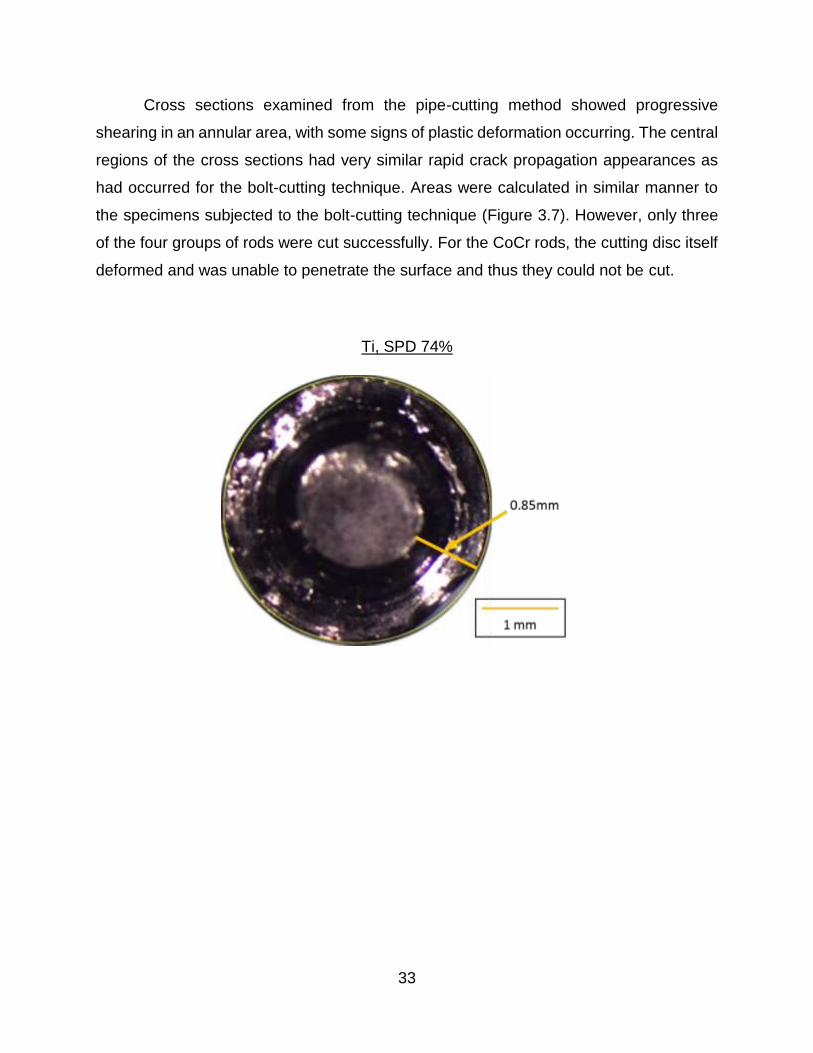
Cross sections examined from the pipe-cutting method showed progressive
shearing in an annular area, with some signs of plastic deformation occurring. The central
regions of the cross sections had very similar rapid crack propagation appearances as
had occurred for the bolt-cutting technique. Areas were calculated in similar manner to
the specimens subjected to the bolt-cutting technique (Figure 3.7). However, only three
of the four groups of rods were cut successfully. For the CoCr rods, the cutting disc itself
deformed and was unable to penetrate the surface and thus they could not be cut.
Ti, SPD 74%

34
SS, SPD 93%
MP35N, SPD 93%
Figure 3.7 Optical images of cut surfaces using the pipe-cutter technique

35
3.1.3 Discussion
These experiments, while preliminary in nature, provided valuable insight into the
types of deformation that occurred using both of the cutting techniques. In the case of
bolt-cutting technique, it was evident that the bolt cutting blades did not plastically deform
the entire cross sectional area in a uniform manner. Instead the fracture surfaces suggest
that the rods underwent an initial slow plastic deformation which reduced their cross-
sectional area. The contact zone between the blade and the rod might then have initiated
a crack which propagated quickly over the remaining cross-section. Alternatively, the
plastic zones created by the initial indentation of the bolt cutter blades might have
interacted and the hydrostatic pressure was sufficient to cause a rapid fracture of the
remaining cross-section. In any case, the high speed of propagation in the central region
was suggested by the scalloped surface with large zones of similar planar orientation.
This also suggested that the forces were highest during the initial compression of
the rod between the blades in the bolt-cutter technique. Operation of the bolt cutters
supported this idea because a large initial force had to be applied and cutting/fracture did
not occur at first. Then, the handles closed quite rapidly and the unconstrained cut end of
the rod was projected away from the bolt cutter. These qualitative observations were
consistent with the characteristics of the fracture surfaces, as previously discussed.
Operation of the bolt-cutting technique required the application of considerable force,
making it evident that either a very strong person or multiple people would be needed to
operate the currently used handheld rod cutters for in-situ rod cutting.
It was also noted that in order to cut the NiCo, CoCr and SS rods using the bolt-
cutting technique, one of the bolt cutter handles had to be braced against the floor so that
the operator’s body weight could be applied. During cutting of the CoCr rod, a small chunk
of the cutting edge of the bolt cutter was removed by a fracture. The rod had slipped away
from centre of the cutting blade surfaces and had moved to the tip region where there
was the least amount of supporting blade material. The blade itself also experienced
plastic deformation from cutting the CoCr rod (Figure 3.3 & 3.8). However, bolt cutter
blades made from higher hardness alloys do exist and could probably cut the CoCr rods
without sustaining damage themselves.

36
The bolt cutter required a large space to operate the handles but this only had to
be on one side of the rod. Thus, such a cutting method could be used for an in-situ spinal
rod cutter. In fact, it has been used, with some difficulties, as discussed in the introductory
chapter of the present thesis.
Figure 3.8 Damaged blades of the bolt cutter after cutting the CoCr rod
The pipe-cutting technique was compromised because the device had been
designed for copper pipe rather than much harder, non-tubular spinal rods. However,
while tedious in nature, shearing the rods using this technique was successful for Ti, SS
and NiCo alloy rods. However, the cutting disc was destroyed when attempting to shear
the CoCr rod. In similar manner to the bolt-cutting technique, at a certain stage, when the
cross-sectional area was reduced by the incremental cutting, a crack rapidly propagated
from the contact point to complete the cutting. Here the idea of interacting plastic zones
was also feasible in that plastically deformed rod material would occur below the cutting
disc and interact with the zone created when the disc was moving over the opposite side
of the rod. However, less force was required to operate the pipe cutter and so the plastic
zone under the cutter-rod contact would be reduced. Thus, the idea of a crack propagating
from the contact point itself looked more feasible.
The pipe-cutting technique took considerable time (several minutes) to complete
the cutting and it would need considerable space around the rod to operate (a radius from
the rod centerline of at least 150 mm) a six-inch radius of the rod. It was hypothesized
that a pipe-cutting tool with a harder cutting wheel material would be able to cut the CoCr
rods. Furthermore, a compact gearing system might be designed to drive the rotations

37
and thus perhaps allow an in-situ spinal rod cutter to be developed with this type of cutting.
However, it would be a difficult design exercise.
3.1.4 Indications of Direction
The bolt cutting technique proved successful for all rod cutting operations as
expected, but there was a small failure of the bolt cutting blades. This suggested that a
minimal amount of blade thickness was required for the high cutting forces experienced.
Additionally, the uncontrolled projection of the rod during the cutting process indicated
that safety precautions which have to be taken during in-situ rod cutting. Both ends of the
rod would have to be constrained and transferring forces to the spinal column would have
to be avoided. To avoid damage to the bolt cutter blades, they would have to be made
from much harder materials. Results and observations from using this technique indicated
that an initial plastic deformation occurs in the rod followed by a subsequent drop in
required applied force and a rapid crack propagation to complete the cutting of the rod.
The pipe-cutting technique could not be used for in-situ rod cutting unless a
mechanism was developed that could work within the space available around the rod in-
situ. It might be worth investigating such a mechanism because even though the pipe
cutting technique took a lot of time, the amount of force required was very low and the
resulting surface was flatter than the surfaces generated from the bolt-cutting technique.
38
3.2 Automated Experimental Approach
3.2.1 Bolt Cutting
The design of an improved spinal rod cutting tool for use in-situ requires some
estimate of the forces needed to cut the rods. In this experiment, forces were applied to
spinal rods using a manual bolt cutter mounted in a materials testing machine. This bolt
cutter was very similar in geometry, particularly blade geometry and blade material
hardness, to those currently in use for cutting spinal rods in-situ. Thus, although the bolt
cutter was not intended for use in spinal surgery, the forces it would apply to spinal rods
were deemed to very similar.
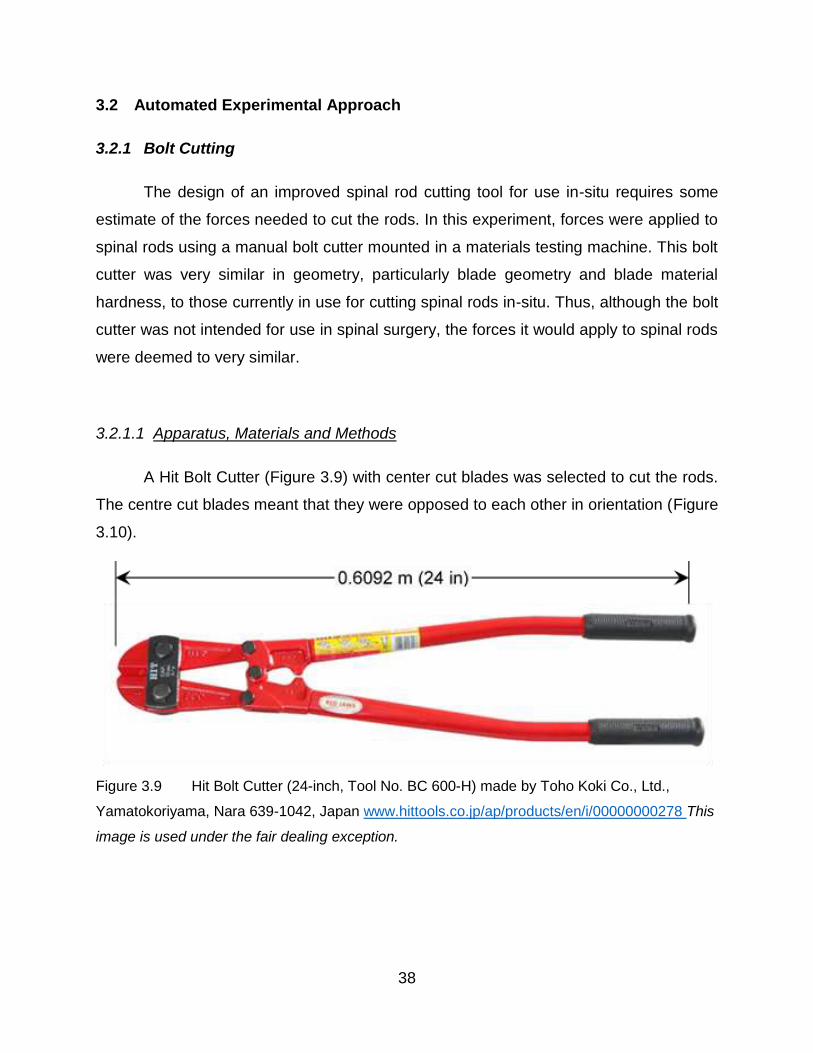
3.2.1.1 Apparatus, Materials and Methods
A Hit Bolt Cutter (Figure 3.9) with center cut blades was selected to cut the rods.
The centre cut blades meant that they were opposed to each other in orientation (Figure
3.10).
Figure 3.9 Hit Bolt Cutter (24-inch, Tool No. BC 600-H) made by Toho Koki Co., Ltd.,
Yamatokoriyama, Nara 639-1042, Japan www.hittools.co.jp/ap/products/en/i/00000000278 This
image is used under the fair dealing exception.

39
Figure 3.10 Centre cut orientation of bolt cutter jaws in the closed position as shown at
www.lawson-his.co.uk/faithfull-faibcj36n-bolt-cutter-jaws-c-p158024 This image is used under
the fair dealing exception.
The bolt cutter was modified to fit into a materials testing machine (Instron 6508,
www.instron.us) in order to apply compressive forces to its handles (Figure 3.11). To
attach the bolt cutter to the Instron, its hollow handles were cut down in length and a 4140
steel cylinder was inserted into the bolt cutter handles using size M8 bolts. The steel
cylinder was modified to form a pin joint. Then, a flat plate “gripper adapter” was fabricated
and attached to the pin joint to allow the grips of the Instron to engage (Figure 3.12). The
gripper adapter included a “support” ledge that prevented vertical slip between the
adapter and the grips of the Instron when transferring compressive forces. In this way,
Figure 3.11 Experimental setup for measuring forces required to cut rods using HIT bolt cutter
40
the bolt cutter was connected to the Instron materials testing machine so that it could
apply forces to the bolt cutter handles.
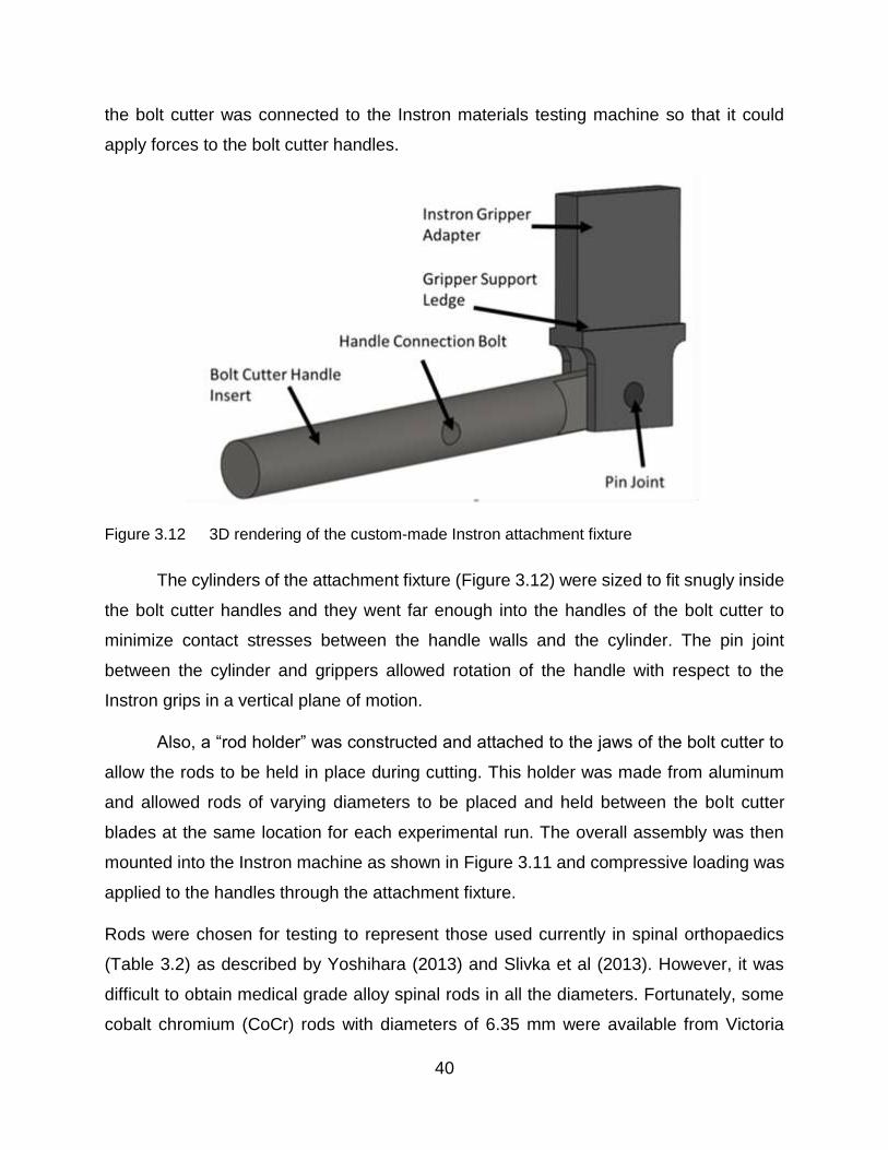
Figure 3.12 3D rendering of the custom-made Instron attachment fixture
The cylinders of the attachment fixture (Figure 3.12) were sized to fit snugly inside
the bolt cutter handles and they went far enough into the handles of the bolt cutter to
minimize contact stresses between the handle walls and the cylinder. The pin joint
between the cylinder and grippers allowed rotation of the handle with respect to the
Instron grips in a vertical plane of motion.
Also, a “rod holder” was constructed and attached to the jaws of the bolt cutter to
allow the rods to be held in place during cutting. This holder was made from aluminum
and allowed rods of varying diameters to be placed and held between the bolt cutter
blades at the same location for each experimental run. The overall assembly was then
mounted into the Instron machine as shown in Figure 3.11 and compressive loading was
applied to the handles through the attachment fixture.
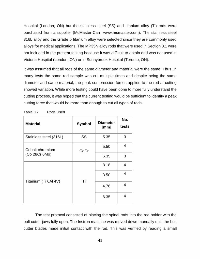
Rods were chosen for testing to represent those used currently in spinal orthopaedics
(Table 3.2) as described by Yoshihara (2013) and Slivka et al (2013). However, it was
difficult to obtain medical grade alloy spinal rods in all the diameters. Fortunately, some
cobalt chromium (CoCr) rods with diameters of 6.35 mm were available from Victoria
41
Hospital (London, ON) but the stainless steel (SS) and titanium alloy (Ti) rods were
purchased from a supplier (McMaster-Carr, www.mcmaster.com). The stainless steel
316L alloy and the Grade 5 titanium alloy were selected since they are commonly used
alloys for medical applications. The MP35N alloy rods that were used in Section 3.1 were
not included in the present testing because it was difficult to obtain and was not used in
Victoria Hospital (London, ON) or in Sunnybrook Hospital (Toronto, ON).
It was assumed that all rods of the same diameter and material were the same. Thus, in
many tests the same rod sample was cut multiple times and despite being the same
diameter and same material, the peak compression forces applied to the rod at cutting
showed variation. While more testing could have been done to more fully understand the
cutting process, it was hoped that the current testing would be sufficient to identify a peak
cutting force that would be more than enough to cut all types of rods.
Table 3.2 Rods Used
Material Symbol Diameter [mm]
No.
tests
Stainless steel (316L) SS 5.35 3
Cobalt chromium (Co 28Cr 6Mo)
CoCr 5.50 4
6.35 3
Titanium (Ti 6Al 4V) Ti
3.18 4
3.50 4
4.76 4
6.35 4
The test protocol consisted of placing the spinal rods into the rod holder with the
bolt cutter jaws fully open. The Instron machine was moved down manually until the bolt
cutter blades made initial contact with the rod. This was verified by reading a small
42
increase of force on the Instron readout. The crosshead of the Instron was moved up a
small amount so that there was minimal blade contact force acting on the rod. Then, the
force transducer and position were set to a reading of zero. The Instron software (Bluehill)
was used to apply compressive loading by instructing the crosshead to move down at 50
mm/ which was judged to be similar to that used in manual operation. When cutting of the
rod was verified by the separation of the rod into two pieces, the Instron was stopped
manually. The forces applied to the handles were recorded automatically throughout the
testing and the peak force was identified.
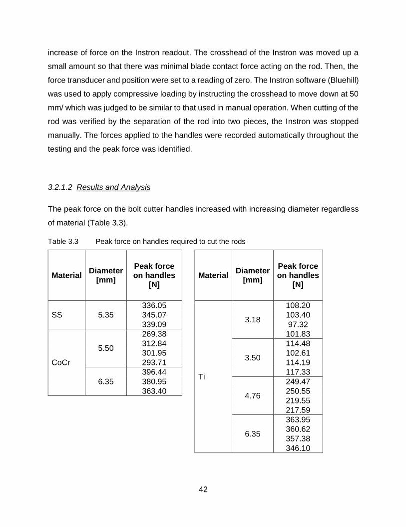
3.2.1.2 Results and Analysis
The peak force on the bolt cutter handles increased with increasing diameter regardless
of material (Table 3.3).
Table 3.3 Peak force on handles required to cut the rods
Material Diameter
[mm]
Peak force on handles
[N]
Material Diameter
[mm]
Peak force on handles
[N]
SS 5.35
336.05
Ti
3.18
108.20
345.07 103.40
339.09 97.32
CoCr
5.50
269.38 101.83
312.84
3.50
114.48
301.95 102.61
293.71 114.19
6.35
396.44 117.33
380.95
4.76
249.47
363.40 250.55
219.55
217.59
6.35
363.95
360.62
357.38
346.10
43
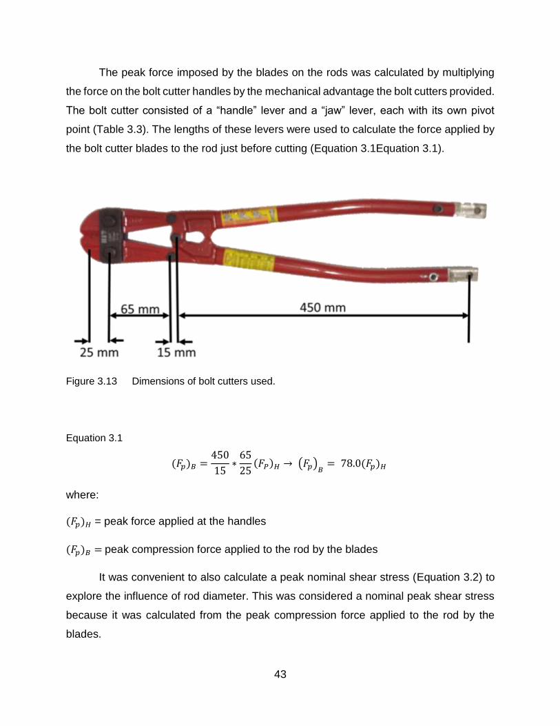
The peak force imposed by the blades on the rods was calculated by multiplying
the force on the bolt cutter handles by the mechanical advantage the bolt cutters provided.
The bolt cutter consisted of a “handle” lever and a “jaw” lever, each with its own pivot
point (Table 3.3). The lengths of these levers were used to calculate the force applied by
the bolt cutter blades to the rod just before cutting (Equation 3.1Equation 3.1).
Figure 3.13 Dimensions of bolt cutters used.
Equation 3.1
(𝐹𝑝)𝐵 =450
15∗
65
25(𝐹𝑃)𝐻 → (𝐹𝑝)
𝐵= 78.0(𝐹𝑝)𝐻
where:
(𝐹𝑝)𝐻 = peak force applied at the handles
(𝐹𝑝)𝐵 = peak compression force applied to the rod by the blades
It was convenient to also calculate a peak nominal shear stress (Equation 3.2) to
explore the influence of rod diameter. This was considered a nominal peak shear stress
because it was calculated from the peak compression force applied to the rod by the
blades.

44
Equation 3.2
(𝜏𝑝)𝑛𝑜𝑚 =(𝐹𝑝)𝐵
𝜋𝑑2
4
where:
(𝜏𝑝)𝑛𝑜𝑚 = peak nominal shear stress
𝑑 = rod diameter
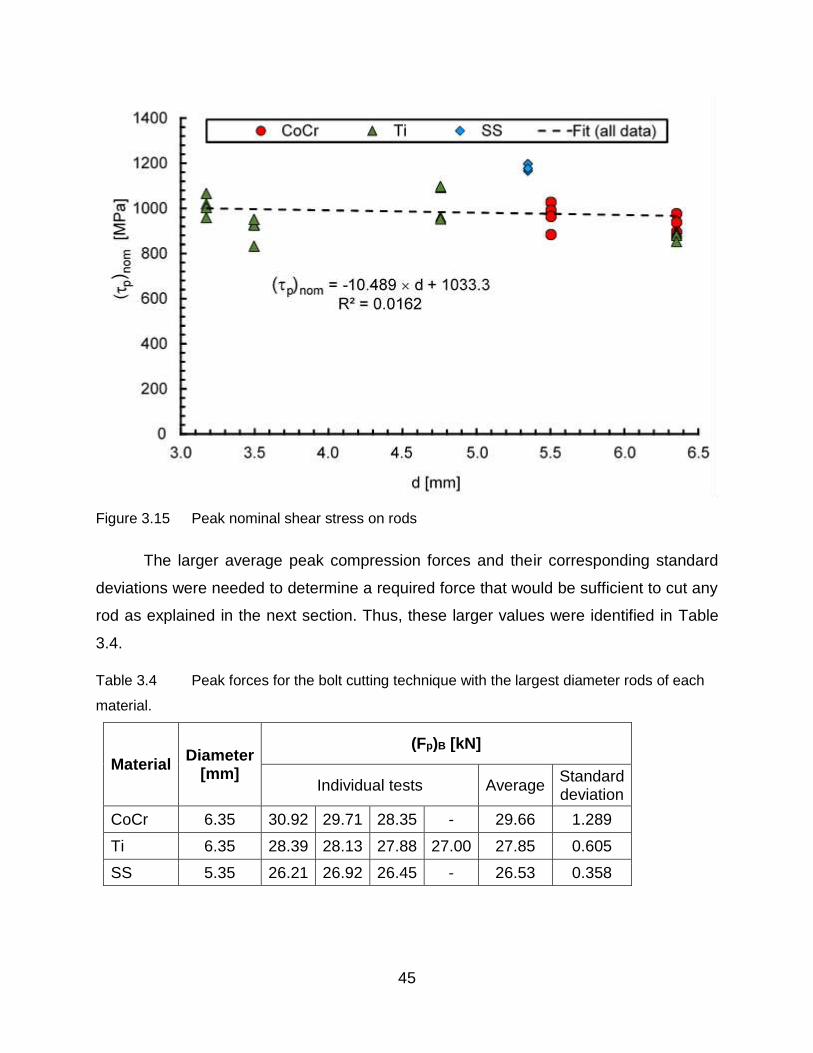
Both the peak forces (Figure 3.14) and the peak nominal shear stresses (Figure 3.15)
were plotted for all the rod specimens and least squares lines were fit to all of the data.
Figure 3.14 Peak compression force on rod using a bolt-cutter
45
Figure 3.15 Peak nominal shear stress on rods
The larger average peak compression forces and their corresponding standard
deviations were needed to determine a required force that would be sufficient to cut any
rod as explained in the next section. Thus, these larger values were identified in Table
3.4.
Table 3.4 Peak forces for the bolt cutting technique with the largest diameter rods of each
material.
Material Diameter
[mm]
(Fp)B [kN]
Individual tests Average Standard deviation
CoCr 6.35 30.92 29.71 28.35 - 29.66 1.289
Ti 6.35 28.39 28.13 27.88 27.00 27.85 0.605
SS 5.35 26.21 26.92 26.45 - 26.53 0.358
46
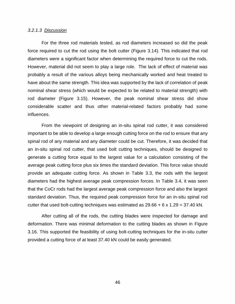
3.2.1.3 Discussion
For the three rod materials tested, as rod diameters increased so did the peak
force required to cut the rod using the bolt cutter (Figure 3.14). This indicated that rod
diameters were a significant factor when determining the required force to cut the rods.
However, material did not seem to play a large role. The lack of effect of material was
probably a result of the various alloys being mechanically worked and heat treated to
have about the same strength. This idea was supported by the lack of correlation of peak
nominal shear stress (which would be expected to be related to material strength) with
rod diameter (Figure 3.15). However, the peak nominal shear stress did show
considerable scatter and thus other material-related factors probably had some
influences.
From the viewpoint of designing an in-situ spinal rod cutter, it was considered
important to be able to develop a large enough cutting force on the rod to ensure that any
spinal rod of any material and any diameter could be cut. Therefore, it was decided that
an in-situ spinal rod cutter, that used bolt cutting techniques, should be designed to
generate a cutting force equal to the largest value for a calculation consisting of the
average peak cutting force plus six times the standard deviation. This force value should
provide an adequate cutting force. As shown in Table 3.3, the rods with the largest
diameters had the highest average peak compression forces. In Table 3.4, it was seen
that the CoCr rods had the largest average peak compression force and also the largest
standard deviation. Thus, the required peak compression force for an in-situ spinal rod
cutter that used bolt-cutting techniques was estimated as 29.66 + 6 x 1.29 = 37.40 kN.
After cutting all of the rods, the cutting blades were inspected for damage and
deformation. There was minimal deformation to the cutting blades as shown in Figure
3.16. This supported the feasibility of using bolt-cutting techniques for the in-situ cutter
provided a cutting force of at least 37.40 kN could be easily generated.

47
Figure 3.16 Close up view of damage to the cutting blades on the bolt cutters
3.2.2 Shear Cutting
Shear cutting of cobalt chromium alloy spinal rods was explored as a possible
concept for developing an in-situ spinal rod cutter. Three shear cutters were made for this
investigation, each with a different geometry. Cutting forces were obtained from testing
using the Instron test machine (Model 6508) that was described in Error! Reference s
ource not found..
3.2.2.1 Materials
Three CoCr spinal rods that each had a diameter of 6.35 mm were tested in the
shear cutters. These rods were the left over segments from various spinal surgeries and
were supplied by Dr. Parham Rasoulinejad (Victoria Hospital, London, ON). These left
over segments were cut from the original rod length using a standard “bench top” cutter.
In the present investigation, shear cutters were made that had two hardened plates with
one sliding over the other to create a plane for shearing (Figure 3.17). The three size
variations of this design were made by changing the dimensions (th, w and D). The
dimensions that were used (Table 3.5) resulted in quite different lower blade components
as shown in Figure 3.18 This variation is sizing was selected to get an idea of the
minimum cutting blade thickness th which is required to successfully cut the spinal rods.

48
Table 3.5 Shear cutter dimensions
Cutter w (mm) th (mm) D (mm)
1 19.05 12.70 12.70
2 12.70 6.35 6.50
3 12.70 3.18 6.50
Figure 3.17 3D rendering of shear cutter
Figure 3.18 Lower blades of the shear cutters

49
The cutters were fabricated using standard machining techniques with care to keep the
metals cool thus avoiding any phase transformations which could have resulted in
localized stress concentrations of the materials. The circular edges which contact the rods
were cut using a final end mill pass of 0.001” (0.0254 mm) to develop a clean and sharp
edge. The cutters were made from AISI 4140 carbon steel alloy which had an elastic
modulus of 190-210 GPa and a Rockwell C hardness (HRC) of 13 (AZO Materials 2017).
This material was easy to machine and could be heat treated subsequently to a much
higher hardness. The present cutters were hardened to 55 HRC by using the heat treating
schedule specified in Table 3.6. A Rockwell C hardness test was performed after the heat
treatment to ensure that the hardness was within ±1 HRC.
Table 3.6 Heat treatment schedule developed from Heat Treating Data Book
(SECO/Warwick 2011)
3.2.2.2 Apparatus and Methods
During a test, the cutter was mounted in an Instron test machine and a CoCr spinal
rod was placed through the hole in the lower blade of diameter as shown in Figure 3.19.
A 'T' shaped plate was used to push the upper blade down along the lower blade channel.
The lower jaw of the Instron was fixed, while the upper jaw could move downward. A force
plate was placed above the upper jaw. After the force plate was zeroed, the upper jaw
was manually jogged downward so that the upper blade touched the rod and the lightly
held it in place. The Instron controls were then set to the zero-extension position and
programmed to push the upper blade downwards at a constant speed of 50 mm/min while
Process Steps
Temperature (°C)
Notes
Annealing 1200-1250 Soak for 3 hours to ensure uniform temperature
Quench 21 Air quench acceptable here since cross section small
Temper 200 30 minutes to achieve 55 ± 1 HRC
Cooling 21 Air cooled

50
the force was recorded. Once the rod was sheared into two pieces, the Instron was
manually stopped.
Figure 3.19 Schematic showing the experimental cutter mounted in the Instron. The red
arrows indicate the direction of motion of the upper jaw.
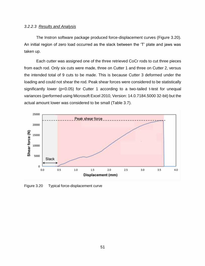
51
3.2.2.3 Results and Analysis
The Instron software package produced force-displacement curves (Figure 3.20).
An initial region of zero load occurred as the slack between the ‘T’ plate and jaws was
taken up.
Each cutter was assigned one of the three retrieved CoCr rods to cut three pieces
from each rod. Only six cuts were made, three on Cutter 1 and three on Cutter 2, versus
the intended total of 9 cuts to be made. This is because Cutter 3 deformed under the
loading and could not shear the rod. Peak shear forces were considered to be statistically
significantly lower (p<0.05) for Cutter 1 according to a two-tailed t-test for unequal
variances (performed using Microsoft Excel 2010, Version: 14.0.7184.5000 32-bit) but the
actual amount lower was considered to be small (Table 3.7).
Figure 3.20 Typical force-displacement curve

52
Table 3.7 Peak forces for the shear cutting technique
Cutter Peak Shear Forces (kN)
Individual tests Average Standard Deviation
1 22.12 23.41 24.21 23.24 1.052
2 24.98 25.92 27.35 26.08 1.190
3 - - - - -
Some visual observations were made. Pictures were taken of the ends of the cut
rods. The cut surfaces were very consistent, typically with cut surfaces perpendicular to
the long axis of the rod (Figure 3.21). The damage to the cutter surfaces was also
examined. Very little visual damage was observed for the cutting edge (Figure 3.22).
Figure 3.21 Typical cut surfaces of CoCr rods, using the shear cutters

53
Figure 3.22 Cutting surface of the upper blade of experimental cutter 2
3.2.2.4 Discussion
The 3.18 mm thick upper blade of Cutter 3 buckled during experimentation, while
the thicker upper blades of Cutters 1 and 2 stayed intact. So an upper blade thickness of
6.35 mm was adequate for a shear cutter made from 4140 steel alloy.
The average peak shear forces for the two cutters were statistically significantly
different but the actual magnitude of the difference was quite small. It was considered
likely that the lower average peak force for cutter 1 was a result of a stiffer cutting surface
due to its larger width, thickness and smaller area of contact because of the larger D
value.
For the 6.35 mm CoCr rods, the average peak force for the shear-cutting technique
(23.24 kN) was considered to be statistically significantly lower (p=0.003) than the
average peak compression force for the bolt-cutting technique (29.66 kN) found in the
previous Section 3.2 (according to a two-tailed t-test for unequal variances performed
using Microsoft Excel 2010, Version: 14.0.7184.5000 32-bit). A required peak shear force
could be identified in the same manner as was used in Section 3.2 for the required peak
compression force. Doing this gave a required peak shear force of 23.24 + 6 x 1.052 =
29.55 kN which was substantially lower than the required peak compression force of
37.40 kN. Also, the cut surfaces were very smooth which would be beneficial for rod
section replacements as discussed in more detail in Chapter 4. This suggested that the

54
shear cutting technique might be better than the bolt cutting technique for an in-situ rod
spinal rod cutter.
3.2.3 Impact Cutting
The idea of cutting rods using a high velocity impact cutting tool was considered
to be worth investigating because it might reduce the force required. This would mean
that the power input requirements would be reduced and the size of the overall tool could
be smaller, making it more convenient for the surgeon to use.
To explore whether impact cutting could actually reduce the amount of force
needed to cut a spinal rod, a preliminary investigation was conducted. The energy needed
to cut the rods was measured with a pendulum impact test using a Charpy test machine
(Figure 3.23), and the fracture surfaces of the rods were visually inspected to determine
whether a suitably smooth and flat. Only CoCr spinal rods were tested.
3.2.3.1 Materials and Methods
Six cobalt chromium rod specimens were tested. Three had a diameter of 6.35 mm
and the other three had a diameter of 6.00 mm. A slitting saw was used to make a small
notch in the center of each rod (Figure 3.24). Coolant was applied and the cutting action
was interrupted frequently to reduce the heating of the rods during the slitting operation
and thus avoid widespread microstructural changes to the cobalt chromium alloy.

55
Figure 3.23 Charpy tester, Satec Systems Inc. (Grove City, Pa) Model SI-1K3
Figure 3.24 Test Specimen
Since the diameter and shape of the specimens could not be changed, the
geometry of the specimens did not correspond to the geometry as specified by the
American Society for Testing and Materials (ASTM) standards (A370-17). The standard
specimen was not as long (55 mm), had a square cross-section and a V-shaped notch (2
mm in depth) with a 0.25 mm radius at the apex of the V-shape. If a spinal rod was to be
cut in-situ using impact, it was likely that only a shallow notch could be cut in it. Heat,
debris generation, and limited access to the rod would prevent the cutting of a deep notch.
56
To simulate this in an approximate way, the notch depth was reduced to 0.5 mm (about
8% of the diameters of the rods).
A slitting saw with a 45 degree angle-symmetric blade was used to cut the V-
shaped notch in the specimens. All of the specimens were aligned in a vice on a milling
machine, to prevent rolling and shifting during cutting. Two cuts, each 1 mm in depth,
were made in succession by a professional machinist, using an oil based machine coolant
to minimize any possible heat generation localized at the V-shaped notch. All of the
specimens were cut at the same time, as the two passes were made across their centers.
The specimens were mounted in the Charpy test machine, with the notch facing
away from the impact wedge, as specified by the ASTM. Each sample was subject to a
single impact. The impact energies were read from the dial on the Charpy test machine.
The change in height of the pendulum of the Charpy test machine before and after impact
was related to the energy loss and had been used to calibrate the dial indicator to give
the readout in Joules. Initially the pendulum was released without a specimen in place to
obtain the frictional energy losses and the dial was adjusted to compensate. Thus, the
impact energies were recorded and the pieces were recovered for macroscopic visual
examination.

57
3.2.3.2 Results
All 6 specimens were completely sheared and impact energies were recorded for
each specimen (Table 3.8).
Table 3.8 Impact energy from the Charpy tests
Test No.
Rod Diameter (mm)
Impact Energy (J)
1
6.00
39.31
2 35.35
3 27.11
Average standard deviation 33.89 6.21
4
6.35
40.67
5 37.96
6 36.60
Average standard deviation 36.60 4.89
After the testing, the rod specimens were visually examined (Figure 3.25). The
specimens had sustained plastic deformation that bent them in the axial direction near
the fracture site. The fracture surfaces themselves were scalloped and the outer edges
were sharp.
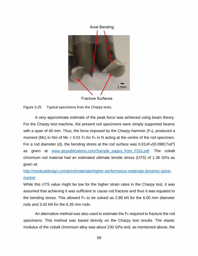
58
Figure 3.25 Typical specimens from the Charpy tests.
A very approximate estimate of the peak force was achieved using beam theory.
For the Charpy test machine, the present rod specimens were simply supported beams
with a span of 40 mm. Thus, the force imposed by the Charpy hammer (Fh), produced a
moment (Mc) in Nm of Mc = 0.01 Fh for Fh in N acting at the centre of the rod specimen.
For a rod diameter (d), the bending stress at the rod surface was 0.01xFh/(0.09817xd3)
as given at www.atcpublications.com/Sample_pages_from_FDG.pdf. The cobalt
chromium rod material had an estimated ultimate tensile stress (UTS) of 1.36 GPa as
given at:
http://medicaldesign.com/print/materials/higher-performance-materials-dynamic-spine-
market
While this UTS value might be low for the higher strain rates in the Charpy test, it was
assumed that achieving it was sufficient to cause rod fracture and thus it was equated to
the bending stress. This allowed Fh to be solved as 2.88 kN for the 6.00 mm diameter
rods and 3.42 kN for the 6.35 mm rods.
An alternative method was also used to estimate the Fh required to fracture the rod
specimens. This method was based directly on the Charpy test results. The elastic
modulus of the cobalt chromium alloy was about 230 GPa and, as mentioned above, the

59
span was 40 mm. For a rod diameter (d), beam deflection was 1.181x10⁻¹⁶xFh/d4 as
given at www.atcpublications.com/Sample_pages_from_FDG.pdf. The energy measured
by the Charpy test machine was considered to consist of the sum of the work to deflect
the rod specimen elastically (1.181x10⁻¹⁶ Fh2/d4) and the work to push the crack through
the diameter of the rod specimen which was Fhxd. Using the average impact energies
from Table 3.8, this allowed a quadratic equation to be solved for F and gave 5.23 kN for
the 6.00 mm diameter rod specimens and 5.43 kN for the 6.35 mm diameter rod
specimens.
3.2.3.3 Discussion
A violent rebounding behavior of the Charpy pendulum was observed during the
impact. This suggested that fracture did not occur immediately on the first impact. The
axial bending of the rod specimen and perhaps the rebounding might have been caused
by the Charpy hammer failing to strike the rod exactly opposite to the notch. As noted
above, the fracture surfaces were scalloped and had sharp edges. However, whatever
method is used to estimate the Fh needed to fracture the CoCr rods of 6.35 mm, it was
considerably lower than that needed for the bolt-cutting or shear-cutting techniques.
3.2.4 Summary
The initial exploration of cutting techniques showed that the bolt-cutting technique
was successful for all rod cutting operations but to avoid damage to the bolt cutter blades,
they would have to be made from hard materials. Results and observations from using
this technique indicated that an initial slow plastic deformation occurred in the rod followed
by a rapid crack propagation to complete the cutting of the rod. The pipe-cutting technique
required a lower force but it could not be used for in-situ rod cutting unless a mechanism
was developed that could work within the space available around the rod.
Based on the tests performed, a peak compression force of 37.40 kN was estimated that
would be sufficient for the bolt-cutter technique to achieve successful cutting any spinal
rod that would be encountered in surgical practice. The blade material would have to be
very hard to avoid progressive damage but as noted in Section 3.1, manual bolt-cutters
have been used successfully for in-situ spinal rod cutting.

60
In a similar calculation to that performed on the results of the bolt-cutting technique, a
peak shear force of 29.66 kN was estimated from the tests performed that would be
sufficient for the shear-cutting technique to achieve successful cutting of any spinal rod
that would be encountered in surgical practice. This value was considerably lower and
suggested that shear-cutting might be a better technique than bolt-cutting for an in-situ
spinal rod cutter. Also, the cut surfaces were smooth and perpendicular to the long axis
of the rod. However, a mechanism would have to be designed that could apply shear-
cutting to the rods in-situ where limited space was available.
An impact-cutting technique for spinal rods in-situ would require much less force
(compared with bolt-cutting or shear-cutting techniques) but would produce a fracture
surface with the potential to cause local tissue abrasion. More significantly, the
surrounding spinal structures and cord would have to be shielded from high transient
reaction forces that could damage them. Furthermore, a notch would probably have to be
cut on the anterior surface of the in-situ rod and then precisely aligned with the impact
hammer. This would be difficult. Thus, the idea of designing an in-situ spinal rod cutter
using an impact-cutting technique was not encouraged.

61
4 Initiating the Design
The previous chapters describe efforts to develop enough knowledge to initiate a
formal design process. Thus, the present chapter proceeds through a formal design
process to the development of two alternative designs. This process is one of the many
that are followed by design engineers. All such formal processes are intended to explain
how a design is developed so that it can be understood and so that continued
development can occur.
4.1 Needs Analysis
4.1.1 When Required
The first case in which rods may need to be cut in-situ is during the initial corrective
surgery for scoliosis or kyphosis. In this procedure, rods are first cut ex-situ (during the
operation but before the rod is placed in the patient) to an estimated final implant length.
This is done by making a rough measurement of the required rod length by placing a
flexible ruler along the spinal column once it is exposed in surgery in order to get a
baseline measurement. It is difficult to determine the required length of the rods even with
the flexible rulers as a guide, since the ruler cannot be positioned right at the neutral axis
which is near the centre of the cross-section of the spinal column. As a result, the final
corrective length of the spine and rods can only be estimated. To err on the side of
caution, surgeons may have a tendency to estimate longer than necessary rod lengths
which can result in the need to cut the rod down to a more appropriate length once spinal
correction has been achieved. A rod that is too long can impinge on the surrounding
tissue, while a rod that is too short will not achieve the desired spinal correction. If an in-
situ rod cutter were developed that was easier to use, it would allow surgeons to cut the
rods a little too long and then cut them down to the correct length in-situ without risking
patient safety.
The second case of which the rod must be cut in-situ arises during revision surgery
for either scoliosis or, more commonly, kyphosis. According to my surgeon co-
supervisors, this is the most common usage case for an in-situ rod cutter. In particular,

62
after the surgery, elderly patients may experience bone degradation (often due to
osteoporosis that may have contributed to the original spinal deformity). This can lead to
aseptic loosening of the pedicle screws. This loosening occurs from the correction forces
applied by the rod pulling out the pedicle screws due to the poor bone stock. Further
deformation of the spine will then occur because the screws can no longer hold it in a
corrective shape. Thus, a revision surgery is performed to deal with this loosening of the
pedicle screws. Sometimes, a replacement of the top section of spinal rod is performed
to install a less stiff rod which reduces the pulling forces on pedicle screws as well as
providing some degree of correction. So, the original rod must be cut and the new less
stiff replacement rod must be connected to the existing rod. This is done using a
connection sleeve (Figure 4.1) which can accommodate different rod diameters.
Figure 4.1 Depiction of connection sleeve used to connect a replacement rod section to the
remaining section of the existing rod
In such procedures, both rod segment ends should align with each other and fit
well into the connection sleeve. This maximizes the contact area between the rods ends
as well as the rod contact with the sleeve, thus increasing the rigidity of the connection.
According to my surgeon co-supervisors, deformation of the original rod near its cut edge

63
could cause difficulties with inserting the rods into the connection sleeve, and sub-optimal
contact with the sleeve wall as shown in Figure 4.2.
Figure 4.2 Comparison of contact between cut rod segments and the connection sleeve
4.1.2 Problems with the Use of the Current In-Situ Rod Cutters
The use of bolt cutters as in-situ rod cutters requires a great deal of input effort
from the surgeon, especially when cutting cobalt chrome alloy rods of the maximum
diameter (6.35 mm) are being cut. Both surgeon co-supervisors said that in order to
operate the bolt cutter for in-situ cutting, it was common practice for another surgeon (or
surgical assistant) to stand on the other side of the patient and then they would both use
their body weight to help apply the effort force to the levers simultaneously. While some
surgeons can operate this cutter on their own providing they are large and strong enough
to do so, there are other issues which pose problems to the patient and the outcome of
the cutting.
In addition to the physical strength required of surgeons to use this tool, the large
size and heavy weight of the bolt cutters make it cumbersome to position and to maintain
the position. If such a heavy tool slips and drops onto the patient, or any rapid changes
in tool position occur while it is inside the patient either positioning it or during the actual
rod cutting, forces may be applied to the spine causing damage. It is possible that the
spinal cord could be damaged permanently.

64
Cutting rods with this tool also poses another problem, since a large amount of
force is applied to the rods. In the final stages of cutting, a rapid crack propagation occurs
and a rapid displacement of the rod ends may occur. Once again, a large enough force
transient could occur to damage the spinal cord or the vertebral bodies.
4.2 Problem Definition
An improved in-situ rod cutter is clearly needed. In designing such a rod cutter, the
actual method of cutting and the mechanism needed to apply the force to the rod are
considered. The mechanism may also be designed to use pneumatic, electric or hydraulic
power to assist in generating the effort force thus allowing the surgeon to concentrate on
positioning the cutter and controlling unwanted shock forces associated with the final
stages of the cutting.
4.3 Design Constraints
For the first iteration of the design process, all proposed alternative designs must
satisfy certain constraints completely (often this must be re-visited and checked at later
stages during the implementation of a design). These design constraints place bounds
and limitations upon any proposed design alternatives. The constraints are determined
based on some judgements made by the author and then applied absolutely. If design
constraints are not specified in this way, very unfeasible design alternatives proliferate
and slow the overall process of achieving an optimal (or at least “harmonic”) design. The
design constraints may be modified to some extent in subsequent iterations of the design
process. For the current design problem, the constraints are specified in the following list
1. Space Available
The existing in-situ rod cutters are measured for size in their maximum required open
position for cutting the large 6.35 mm rods. It was determined that the rods are located at
a depth of about 60 mm from the posterior skin surface of the exposed spine. At the
surface of the skin, the rod cutters are measured to be 80 mm in width in their open state.
Just beneath the rod, at a depth of 66.35 mm the rod cutters are measured to be 35.35
mm wide in their open state. These measurements, forming a trapezoidal bounding box

65
are close to the maximum space available for a rod cutting mechanism, since it is difficult
to fit the existing cutters into place in-situ. A distance along the rod of about 25.4 mm is
enough to allow the cutter to fit between two pedicle screws. The anterior distance
between the rod and the spinal column is about 15 mm, which does not increase with
smaller rod diameters due to the design of the pedicle screws. This anterior side of the
spine must not be in contact with the rod cutter during cutting, so the cutting jaws must
not protrude deeper than the rod by 15 mm. The bounding box depicted by Figure 4.3 shows
the maximum space available for the rod cutter.
Figure 4.3 Dimensions of space available for fitting the in-situ cutter into the exposed spine.
2. Use of Mechanical Cutting

66
In Chapter 3, different types of cutting were investigated as options for in-situ rod
cutting. The pipe cutting technique could not work due to the space constraints as there
needs to be far more room around the rod on all sides than available. Other possible rod
cutting techniques such as electrical discharge machining, sawing, water jet cutting, and
laser cutting were all considered to pose significant risks to the patient. Any heat
generation is dangerous as it can traumatize the spinal cord, while debris generation
poses the risk of metalloids related illnesses to the patient. The high pressures involved
with water jet cutting are difficult to control and could easily damage the spinal cord. For
these reasons, it was decided to restrict the cutting method to be mechanical (either shear or
compression) with minimal debris and heat generation.
3. Cutting Force Required
Experimental work in Chapter 3 determined the forces required to cut the rod in both
shear and compression. The shear force was determined by cutting the rods using two
cleaving jaws positioned next to each other to share a common cutting plane, while the
compression force was determined using bolt cutters which pinched and compressed the
rod with aligned jaws closing on opposite (lateral) sides of the rod. In Chapter 3, it was
found that the 6.35 mm CoCr rods required the most force to cut, the average force to cut
these rods in shear was found to be 23.24 ± 1.05 kN (avg ± SD) and 29.66 ± 1.29 kN in
compression. To ensure that all alternative mechanism designs could cut 6.35 mm CoCr
rods, a value of six times the standard deviation was added to the average value. Thus,
any mechanism design for shear cutting must provide a force of at least 29.6 kN on opposing
lateral sides of the rod and any mechanism design for compression cutting must provide a force
of at least 37.4 kN on opposing lateral sides of the rod.
4. Power Source
The existing in-situ rod cutters are manually operated. There are several issues with
manual operation which are undesirable in a rod cutter tool. Often two or three surgeons
must be involved in the cutting process since it takes a large amount of strength to close
the current in-situ rod cutter handles in order to cut the rod. This multiple surgeon
approach leads to complications such as accurately holding the tool in place as well as

67
having the surgeons match each other’s input efforts to close the handles so the tool does
not displace the central long axis of the rod too dramatically. This multiple surgeon
approach is also an inconvenience as it requires that both surgeons are strong and
coordinated enough to effectively operate the bolt cutters. This is quite difficult. A major
concern with these manually cutters is the application of inadvertent forces on the spine
at the instant of cutting. Since the final stage of the rod failure is a bit violent, surgeons
must be prepared to control both their physical effort input and the rod cutter tool once
the cut is complete. This is analogous to the feeling of pulling hard on a door which
becomes suddenly unlocked. So, failure to control their physical efforts could result in the
existing in-situ rod cutters pulling or pushing on the spinal column anatomy. It is strongly
desirable that minimal strength be required by the surgeon to operate an in-situ rod cutter,
thus it is necessary that a non-manual power source should be used to cut the rod.
Hydraulic, pneumatic and electrical power sources could be used, but consideration must
be made towards patient safety as well. In the case of hydraulics, large compressor
equipment must be used to generate the hydraulic pressures. In addition, hydraulic oils
are dangerous to human health and should not be in an operating theatre. Hospitals have
200 psi air lines available for pneumatics, and 120 and 240 v electrical lines for electrical
equipment. Thus, any alternative design must either use pneumatic pressure or electricity to
power the mechanisms.
5. Material Selection
Material selection is important in a clinical setting such as an operating theatre, as all
equipment must be able to withstand sterilization. In the case of tools which go inside
patients, an elevated temperature and pressure autoclave typically uses 2 atmospheres
of pressure and about 135 ⁰C of superheated steam (3% humidity) to sterilize the tools.
This process can greatly accelerate corrosion of materials, so materials should be
selected to withstand corrosion. Typical metals used for surgical instruments (ASTM
F899-12b) are 316L and 400 series stainless steels. Except for the blades, 316L stainless
steel is often used. To avoid damage and failure of rod cutting blades, the hardness must
be high enough to avoid plastic deformation and this can be achieved with 420 and 440
stainless steels. The existing in-situ bolt cutters are made from the above grades of
68
stainless steel which satisfies these constraints. So, rather than consider an alternative
material, it was decided that any prototype designs should use 420 or 440 stainless steel for the
blades and 316L stainless steel for the other parts of the mechanism.
6. Limitations in the Scope of the Current Design Iteration
It was considered counter-productive to attempt to develop too many criteria because
it would encumber the design process. The identification of the most important criteria
would allow an iteration of the design process in which a prototype could be fabricated
and tested. The experience gained in this first iteration would allow a second design
iteration that would be much closer to optimal when judged according to the criteria (and
much more certain that all of the constraints have been satisfied) when checked at the
prototype stage. During subsequent design iterations, the issues identified below would
have to be considered and would either remain as constraints or be developed into
criteria.
Existing in-situ rod cutters do not have issues with fracture and fatigue problems, as
the components are sized to withstand this. This design exercise does not consider
detailed stress analysis and fatigue predictions, so similar sized components to that of
the existing in-situ rod cutters must be used to minimize the chances of fatigue and
fracture occurring in the designed mechanisms. In order to verify the lack of fatigue and
fracture problems, prototype construction and testing would eventually be performed.
The cost, safety, ergonomics and marketing are aspects not considered in the present design
exercise, but can be addressed once the designed rod cutters are prototyped and closer to the
final stages of implementation. A large design improvement over the current in-situ rod
cutters would increase the ease of sales to hospitals, and could justify a larger price point
in relation to the current rod cutters. A large enough improvement on design could be
achieved the above constraints were satisfied, as they address the major issues pointed
out by surgeons using the current in-situ rod cutters. Safety issues, such as pinching parts
as well as ergonomics and appearances can be implemented in future design iterations
which would involve surgeon feedback and testing.
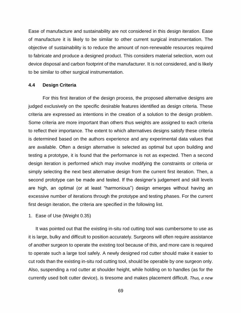
69
Ease of manufacture and sustainability are not considered in this design iteration. Ease
of manufacture it is likely to be similar to other current surgical instrumentation. The
objective of sustainability is to reduce the amount of non-renewable resources required
to fabricate and produce a designed product. This considers material selection, worn out
device disposal and carbon footprint of the manufacturer. It is not considered, and is likely
to be similar to other surgical instrumentation.
4.4 Design Criteria
For this first iteration of the design process, the proposed alternative designs are
judged exclusively on the specific desirable features identified as design criteria. These
criteria are expressed as intentions in the creation of a solution to the design problem.
Some criteria are more important than others thus weights are assigned to each criteria
to reflect their importance. The extent to which alternatives designs satisfy these criteria
is determined based on the authors experience and any experimental data values that
are available. Often a design alternative is selected as optimal but upon building and
testing a prototype, it is found that the performance is not as expected. Then a second
design iteration is performed which may involve modifying the constraints or criteria or
simply selecting the next best alternative design from the current first iteration. Then, a
second prototype can be made and tested. If the designer’s judgement and skill levels
are high, an optimal (or at least “harmonious”) design emerges without having an
excessive number of iterations through the prototype and testing phases. For the current
first design iteration, the criteria are specified in the following list.
1. Ease of Use (Weight 0.35)
It was pointed out that the existing in-situ rod cutting tool was cumbersome to use as
it is large, bulky and difficult to position accurately. Surgeons will often require assistance
of another surgeon to operate the existing tool because of this, and more care is required
to operate such a large tool safely. A newly designed rod cutter should make it easier to
cut rods than the existing in-situ rod cutting tool, should be operable by one surgeon only.
Also, suspending a rod cutter at shoulder height, while holding on to handles (as for the
currently used bolt cutter device), is tiresome and makes placement difficult. Thus, a new

70
tool should minimize the overall weight, without risking fatigue or fracture, and consider how the
device should be held by the surgeon to achieve easy and accurate positioning.
2. Minimize the Risk of High Transfer of Forces to the Patient (Weight 0.35)
A major concern with the operation of the existing in-situ bolt cutter is the risk of
transfer of significant forces to the spinal cord, since trauma to the spinal cord can create
permanent disability to the patient. The forces required to cut the largest and strongest
rods (6.35 mm diameter CoCr) have been specified in the constraints. These forces have
also been specified in the constraints to act on the lateral sides of the rod. To minimize the
risk of high transfer forces, the blades should be aligned to avoid high reaction forces and torques.
Once the cutting occurs, high impulse forces might occur and designs should seek to minimize
them.
3. Shape of Cut Zone (Weight 0.2)
After rods are cut in-situ, the cut surface should be as close as possible to perpendicular to the
long axis of the rod and have minimal bending or crushing of the rod (Figure 4.4).
Figure 4.4 Ideal surface geometry of spinal rod after it has been cut
In Chapter 3, the end surfaces of rods were shown to vary with the different rod cutting
techniques investigated. The quality of the surface is important to the use of rod extension
clamps that join two rod ends together as discussed in greater detail in the
aforementioned sections of this chapter. Additionally, a bent rod end could push against
adjacent tissues, or it could interfere with the rod clamps which are used to adjust the
rod’s position and axial rotation once it has been implanted (Figure 4.5).
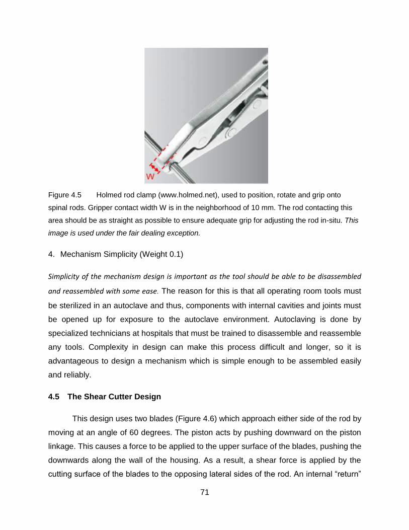
71
Figure 4.5 Holmed rod clamp (www.holmed.net), used to position, rotate and grip onto
spinal rods. Gripper contact width W is in the neighborhood of 10 mm. The rod contacting this
area should be as straight as possible to ensure adequate grip for adjusting the rod in-situ. This
image is used under the fair dealing exception.
4. Mechanism Simplicity (Weight 0.1)
Simplicity of the mechanism design is important as the tool should be able to be disassembled
and reassembled with some ease. The reason for this is that all operating room tools must
be sterilized in an autoclave and thus, components with internal cavities and joints must
be opened up for exposure to the autoclave environment. Autoclaving is done by
specialized technicians at hospitals that must be trained to disassemble and reassemble
any tools. Complexity in design can make this process difficult and longer, so it is
advantageous to design a mechanism which is simple enough to be assembled easily
and reliably.
4.5 The Shear Cutter Design
This design uses two blades (Figure 4.6) which approach either side of the rod by
moving at an angle of 60 degrees. The piston acts by pushing downward on the piston
linkage. This causes a force to be applied to the upper surface of the blades, pushing the
downwards along the wall of the housing. As a result, a shear force is applied by the
cutting surface of the blades to the opposing lateral sides of the rod. An internal “return”

72
linkage is used to restore the blades to their starting position as the piston moves to its
original position (Figure 4.7).
Figure 4.6 Shear-cutting design

73
Figure 4.7 Schematic showing interior components and how they link together
The tips of the blades are designed to shear the rod on a single plane, while
providing a relief zone for the rod to move to after shearing (Figure 4.8). The relief zone
width was sized to accommodate the largest diameter surgical rod at 6.35 m. Since there
are two blades, this width was 3.2 mm which is slightly larger than half of the rod diameter.
The blade tip length h was set to 12.7 mm to ensure that forces did not act close to the
edge of the blades.

74
Figure 4.8 Cutting blade geometry shown in the blade closed position.
This design allowed shear cutting using forces (Constraint 2 - Use of Mechanical Cutting)
applied to the opposing lateral sides of the rod (Constraint 3 - Cutting Force Required)
and it fit into the space available (Constraint 1 - Space Available). The power source was
a pneumatic cylinder (Constraint 4 - Power Source) that could be detached from the rest
of the cutter mechanism and the material for the cutting blades would be 440 stainless
steel while the rest of the mechanism would be made from 316L stainless steel
(Constraint 5 - Material Selection). Components were sized using the existing in-situ rod
cutters as a guide and thus should not have high stresses or fatigue problems (part of
Constraint 6 - Limitations in the Scope of the Current Design Iteration).
The design was considered to be easy to use and should not introduce high transfer
forces (Criteria 1 and 2). Based on the testing in Section 3.3, it was considered likely that
the shape of the cut zone would be ideal (Criteria 3).

75
The cutting mechanism was quite simple (Criteria 4) but it had to be assumed that a large
enough pneumatic cylinder could be specified to supply the required force. More detailed
discussions of this alternative design are given in the next chapter where the optimal
design is chosen.
4.6 Bolt Cutter Design
This design has the same bolt-cutting technique (Constraint 2 - Use of Mechanical
Cutting) as the existing manual in-situ rod cutters (Figure 2.16 and Figure 2.17). The main
feature of this design is the linkage that connects a pneumatic piston (Constraint 4 - Power
Source) to the blades (Figure 4.9). This linkage provides considerable mechanical
advantage and thus allows a large enough force to be applied to the opposite lateral sides
of the rod (Constraint 3 - Cutting Force Required). The entire mechanism fits within the
space allowed (Constraint 1 - Space Available).
Figure 4.9 3D Rendering of bolt cutter design
The links were sized using the existing in-situ rod cutters as a guide (part of
Constraint 6 - Limitations in the Scope of the Current Design Iteration), and all
components were to be fabricated from stainless steel (Constraint 5 - Material Selection).
76
The pneumatic cylinder would be connected to the supply line in the operating theatre.
During operation, the pneumatic cylinder would be pressurized and the mechanism would
close the blades around a rod (Figure 4.10 and Figure 4.11). After cutting, the piston
direction would be reversed, using the double action of the pneumatic cylinder, and the
jaws would open to be ready for the next cutting action.
Figure 4.10 Bolt cutting design shown in its opened state, top view
Figure 4.11 Bolt cutting design shown in its closed state, top view

77
This alternative design was considered to be easy to use and should not introduce
high transfer forces (Criteria 1 and 2). Based on the testing in Section 3.3, it was
considered likely that the shape of the cut zone would not be ideal and so Criteria 3 would
not be well addressed. However, the cutting mechanism was quite simple (Criteria 4).
More detailed discussions of this alternative design are given in the next chapter where
the optimal design is chosen.
4.7 Design Matrix
Based on the criteria set forth in this chapter, the proposed design alternatives, the
shear cutter design and bolt cutter design, were scored in these categories using the
decision matrix shown in Table 4.1
Table 4.1 Decision matrix used to determine the optimal design
Criteria Weighting Shear Cutter Bolt Cutter
1. Ease of Use 0.35 8 7
2. Force Transfer 0.35 8.5 8
3. Cut Zone Shape 0.20 10 7
4. Simplicity 0.10 6 5
Total 8.4 7.2
Shear Cutter is the optimal design
The authors experience and judgement were used to determine the scores for
each design. Both designs were considered easy to use, since they implement a
pneumatic power source and are designed to be operated by only one surgeon. The
weight of the designs would be quite high given the amount of bulk metal required to
withstand the high forces of cutting. However, the bolt cutter has an additional linkage to
achieve mechanical advantage which would increase its bulk. Thus, the shear cutter was
given a score of 8 but the bolt cutter had a score of 7.
Both designs were developed to cut rods using opposing forces, with their cutting
blades aligned on either side of the rod as required by Constraint 3 - Cutting Force
Required. This lateral alignment of the blades should reduce transfer of forces to the
spine, as the equal and opposite forces result in a net applied force of zero. However,
since the stresses of the rod during cutting vary with the shear cutting and bolt cutting
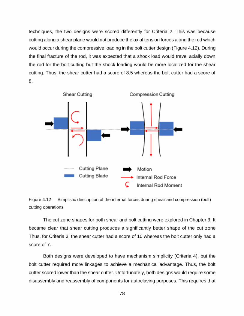
78
techniques, the two designs were scored differently for Criteria 2. This was because
cutting along a shear plane would not produce the axial tension forces along the rod which
would occur during the compressive loading in the bolt cutter design (Figure 4.12). During
the final fracture of the rod, it was expected that a shock load would travel axially down
the rod for the bolt cutting but the shock loading would be more localized for the shear
cutting. Thus, the shear cutter had a score of 8.5 whereas the bolt cutter had a score of
8.
Figure 4.12 Simplistic description of the internal forces during shear and compression (bolt)
cutting operations.
The cut zone shapes for both shear and bolt cutting were explored in Chapter 3. It
became clear that shear cutting produces a significantly better shape of the cut zone
Thus, for Criteria 3, the shear cutter had a score of 10 whereas the bolt cutter only had a
score of 7.
Both designs were developed to have mechanism simplicity (Criteria 4), but the
bolt cutter required more linkages to achieve a mechanical advantage. Thus, the bolt
cutter scored lower than the shear cutter. Unfortunately, both designs would require some
disassembly and reassembly of components for autoclaving purposes. This requires that

79
the hospital sterilization staff must have additional training to perform the assembly, so
neither design scored exceptionally high in this category.
Overall, the shear cutter had a score of 8.4/10, which was higher than the bolt
cutter score of 7.2/10. The shear cutter design was selected for the next stages of design,
in which implementing and testing the mechanisms of the design occurs.
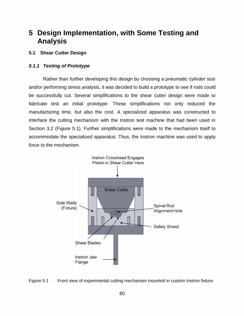
80
5 Design Implementation, with Some Testing and Analysis
5.1 Shear Cutter Design
5.1.1 Testing of Prototype
Rather than further developing this design by choosing a pneumatic cylinder size
and/or performing stress analysis, it was decided to build a prototype to see if rods could
be successfully cut. Several simplifications to the shear cutter design were made to
fabricate test an initial prototype. These simplifications not only reduced the
manufacturing time, but also the cost. A specialized apparatus was constructed to
interface the cutting mechanism with the Instron test machine that had been used in
Section 3.2 (Figure 5.1). Further simplifications were made to the mechanism itself to
accommodate the specialized apparatus. Thus, the Instron machine was used to apply
force to the mechanism.
Figure 5.1 Front view of experimental cutting mechanism mounted in custom Instron fixture

81
In this less complex, experimental version of the shear cutter, linkages and pins
were not included but the fundamental cutting mechanism was not changed (Figure 5.2).
The operation of the simplified design was to be very similar to the original design with
the blades being driven using a single piston to move them along the housing wall. In
order prevent internal rotation of the blades, a central aligning post feature was added to
the casing (Figure 5.2). Since smaller rods require that the blades travel a larger distance
before contacting the rod, the blades cutting face length and the total blade displacement
length had to be adjusted to prevent an over-extension of the blades into the spinal
column when cutting these smaller diameter rods.
Figure 5.2 Assembly of experimental cutting mechanism
The shear cutting operation involved motion of the blades in the direction of force
application (Figure 5.3). Initially, the tool was in the retracted starting position, where it
was centered on top of the rod to be cut. During the cutting operation the input force was
applied to the piston from the Instron crosshead, which pushes on the cutting blades. The
cutting blades move downwards sliding against the housing wall, the ends contacting the
lateral sides of the rod and thus squeezing it. As the mechanism reached the final position,

82
the rod was sheared and the shear cutter could be manually returned to its starting
position.
Figure 5.3 Cutting sequence of the mechanism
In order to cut the hard cobalt alloy rods, the cutting blades were manufactured
from AISI O2 grade tool steel, rather than a stainless steel specified for the shear cutter
design. This steel was hardened to 55 HRC so that damage to the cutting edge would be
minimal. All other components were made from AISI 4140 grade steel which also differed
from the stainless steel specified for the shear cutter design. These materials were easier
to obtain and were expected to cut in a similar manner to the specified one.
5.1.2 Force Analysis
Although it was known that the forces would be quite high, the fracture described
in the previous section was not expected. Therefore, to further investigate the shear cutter
design a force analysis was performed. Forces were only considered in the vertical plane
because it was assumed that the forces causing the twisting moment in the horizontal
plane would not have a substantial effect on the forces in the vertical plane. However, it
was recognized this twisting moment would cause reaction forces on the pedicle screws
holding the rod that might have been detrimental to rod fixation after the cutting action. A
free body diagram (Figure 5.4) was constructed to reflect the static forces acting on the
cutting blade, when the shear cutter design was in the closed position. Dimensions used

83
in this static analysis are shown in Figure 5.5, with the origin located at the lowest contact
between the blade and the housing. With the goal of determining the mechanical
advantage offered by the shear cutter design, several assumptions had to be made:
Assumptions:
The blade is only in contact with the housing on the outer side, thus only one friction
force is considered.
The location of point C (Figure 5.4) is unknown, and must be determined
The force applied from the piston to the top of the blade is concentrated at the
outer edge of the blade
The rod force is the maximum force required to cut the rod using a shear technique
as determined in Chapter 3 (FNRod = 29.25 kN)
The coefficient of friction, µ = 0.30 is chosen since the housing is a mild steel in
contact with a polished O2 blade steel.
Figure 5.4 Free body diagram of the cutting blade in the closed position

84
Figure 5.5 Dimensions necessary to perform analysis of forces shown in Figure 5.4
The equations summing the forces in the x and y directions provide enough information
to determine the force acting on the piston FN,Piston, and the normal force FN,1.
∑ 𝐹𝑥 = 0
Equation 5.1
−𝐹𝑁,𝑅𝑜𝑑 + 𝐹𝑁,1 (cos 25 − 𝜇 cos 65) − 𝜇𝐹𝑁,𝑃𝑖𝑠𝑡𝑜𝑛 = 0
∑ 𝐹𝑦 = 0
Equation 5.2
𝜇𝐹𝑁,𝑅𝑜𝑑 + 𝐹𝑁,1(sin 25 + 𝜇 sin 65) − 𝐹𝑁,𝑃𝑖𝑠𝑡𝑜𝑛 = 0
𝐹𝑁,𝑃𝑖𝑠𝑡𝑜𝑛 = 48.03 𝑘𝑁

85
𝐹𝑁,1 = 56.39 𝑘𝑁
Thus the mechanical advantage of the system can now be determined by taking the ratio
of the output shear force to the required input force on the piston:
𝑀𝐴 = 𝐹𝑁,𝑅𝑜𝑑
2 ∗ 𝐹𝑁,𝑃𝑖𝑠𝑡𝑜𝑛=
29.55
96.06= 0.31
Since the mechanical advantage is less than 1, this indicates that the shear cutter design
requires a greater input force than it outputs to cut the rod.
The location of the normal force from the blade contact with the case can now be
determined:
∑ 𝑀𝐶 = 0
Equation 5.3
𝐹𝑁,𝑃𝑖𝑠𝑡𝑜𝑛(8.88 − 𝑑2) + 𝜇𝐹𝑁,𝑃𝑖𝑠𝑡𝑜𝑛(19.05 − 𝑑1) − 𝐹𝑁,1(𝑑1 + 3.175) + 𝜋𝐹𝑁,1(𝑑2 + 9.31) = 0
where:
𝑑2 = 𝑑1 tan 25
In Equation 5.3, all distances are in mm and all forces are in kN. Substituting in the
known forces and solving for d1 and then d2 gives:𝑑1 = 11.08
𝑑2 = 5.16
5.1.3 Discussion
The first prototype of the shear cutting design was fabricated and tested in the
Instron. After one successful preliminary shearing of a 6.35 mm cobalt chromium alloy
rod, one of the blades sustained a brittle fracture (Figure 5.6). The likely cause of the
blade fracture was the misalignment of cutting blades when initially contacting the rod
(Figure 5.7) that might have been caused by a shift in the housing alignment. However,
the experimental version of the cutter did not have linkages to hold the blades in a parallel
orientation. Instead, the blades were positioned manually prior to the cutting sequence
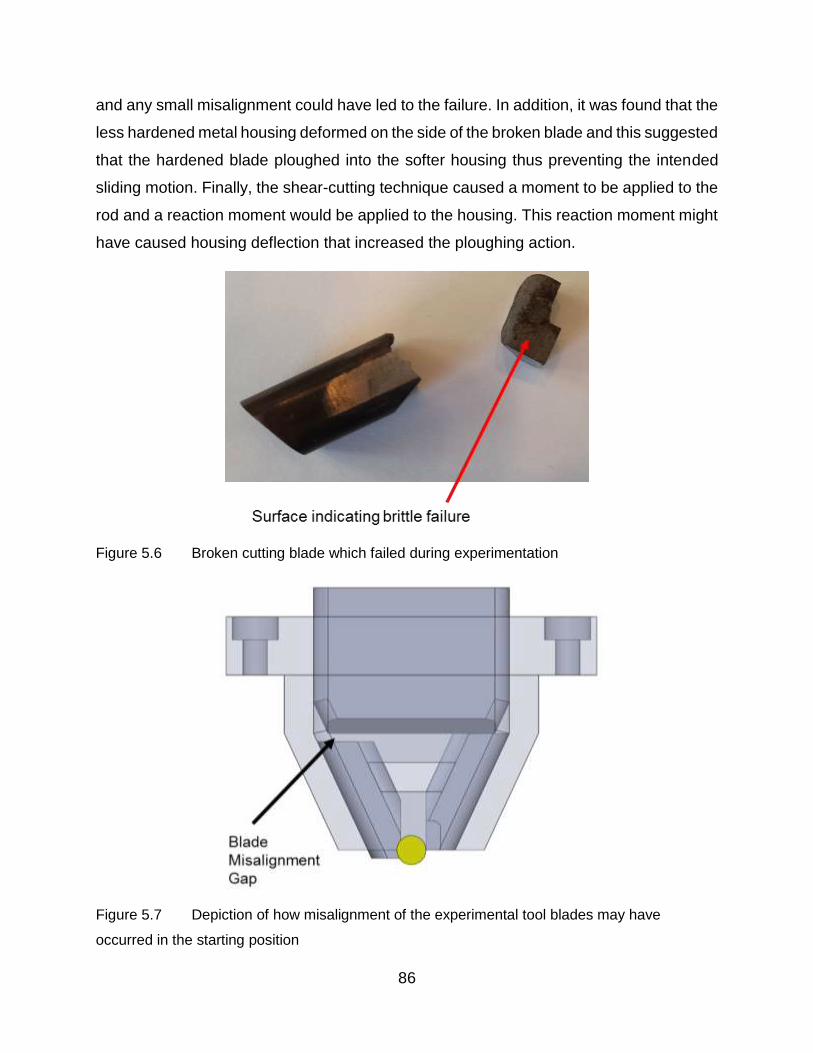
86
and any small misalignment could have led to the failure. In addition, it was found that the
less hardened metal housing deformed on the side of the broken blade and this suggested
that the hardened blade ploughed into the softer housing thus preventing the intended
sliding motion. Finally, the shear-cutting technique caused a moment to be applied to the
rod and a reaction moment would be applied to the housing. This reaction moment might
have caused housing deflection that increased the ploughing action.
Figure 5.6 Broken cutting blade which failed during experimentation
Figure 5.7 Depiction of how misalignment of the experimental tool blades may have
occurred in the starting position

87
The functional problems with this shear-cutter mechanism were not the only issue
with this design. Based on the aforementioned analysis of forces during cutting, it is clear
that this mechanism does not provide any mechanical advantage to assist in shearing
rods. The amount of input force gets reduced by two thirds thus, a pneumatic cylinder
would have to be quite large to deliver such high forces to operate the cutter. It now seems
clear that the force analysis, should have been performed earlier, it might have
discouraged the development and testing of a prototype. For these reasons, the second
design alternative was pursued instead of this shear cutter design.

88
5.2 Bolt Cutter Design
5.2.1 Force Analysis
An important feature of the bolt cutter was the linkage that was intended to give a
mechanical advantage to the overall mechanism. This would allow the pneumatic cylinder
to be small and thus improve the ease of use of the bolt cutter. In Section 3.2, a manual
bolt cutter was analyzed to determine the mechanical advantage. The bolt cutter design
alternative (Figure 5.8) was analyzed in somewhat similar but more rigorous manner to
determine the mechanical advantage the mechanism provides. This information is then
used to determine the sizing of the pneumatic cylinder powering the mechanism.
Figure 5.8 Drawing showing the dimensions necessary to calculate the mechanical
advantage of the bolt cutter in its closed position
A free body diagram was generated for each of the segments needed to perform the
calculation of mechanical advantage. Link AB is shown in Figure 5.9, and the static
equilibrium equations are derived as follows.

89
Figure 5.9 Free body diagram link AB (the cutting blade) in the closed position
Note that there is no force acting on point A in the x direction. Since the connecting
member between the blades is a two force member in static equilibrium, there is no
force acting in the x direction thus,
∑ 𝐹𝑥 = 0
𝐹𝐵𝑥 = 0
The moment is then taken about point A which acts as the fulcrum in this lever:
∑ 𝑀𝐴 = 0
−12.7𝐹𝑅𝑜𝑑 − 160.3𝐹𝐵𝑦 = 0
Equation 5.4
𝐹𝐵𝑦 =−12.7
160.3𝐹𝑅𝑜𝑑

90
As shown above, the pin force in the y direction is known in terms of the rod force. The
equations derived from the free body diagram of link BD (Figure 5.10) can now be solved
for:
Figure 5.10 Free body diagram of link BD
The moment is taken about the fulcrum of this link, at point D:
∑ 𝑀𝐷 = 0
148.6𝐹𝑐 sin 61.7 − (148.6 + 75.9)𝐹𝐵𝑦+ 148.6𝐹𝑐 cos 28.3 = 0
Equation 5.5
𝐹𝑐 =(148.6 + 75.9)𝐹𝐵𝑦
(148.6 sin 61.7 + 148.6 cos 28.3)
Equation 5.4 and Equation 5.5:
Equation 5.6
𝐹𝑐 = −(148.6 + 75.9)
(148.6 sin 61.7 + 148.6 cos 28.3)∗
12.7
160.3𝐹𝑅𝑜𝑑
Thus, FC is now expressed in terms of FRod (Equation 5.6), and by inspecting the free
body diagram of the piston link pin (Figure 5.11) it is obvious that FPiston = 2*FC*cos61.7

91
thus FPiston can now be expressed in terms of FRod (Equation 5.7) to get the mechanical
advantage.
Figure 5.11 Free body diagram of the piston connecting pin
Equation 5.7
𝐹𝑃𝑖𝑠𝑡𝑜𝑛 = 2 ∗ ((148.6 + 75.9)
(148.6 sin 61.7 + 148.6 cos 28.3∗
12.7
160.3𝐹𝑅𝑜𝑑) cos 61.7
Thus, the mechanical advantage is FRod/FPiston = 8.17 or FPiston is determined to be:
𝐹𝑃𝑖𝑠𝑡𝑜𝑛 = 0.1224𝐹𝑅𝑜𝑑
Knowing this relationship (mechanical advantage) between the FRod and FPiston, and the
required force, of 37.4 kN (FRod) to cut the rod using the bolt cutting technique, the piston
diameter can be sized. The pneumatic lines in hospitals typically supply a pressure of 200
psi (1.38 MPa), thus, the minimum piston diameter could be determined as follows:
Equation 5.8
𝐹𝑃𝑖𝑠𝑡𝑜𝑛 = 𝑃𝑔𝑢𝑎𝑔𝑒 ∗ 𝐴𝑝𝑖𝑠𝑡𝑜𝑛
where:
𝐹𝑃𝑖𝑠𝑡𝑜𝑛 = 37.4 ∗ 0.1224 = 4.578 𝑘𝑁, (required force for the mechanism to be able
to cut the rod)
𝑃𝑔𝑢𝑎𝑔𝑒 = 1.38 𝑀𝑃𝑎 , (supply pressure)
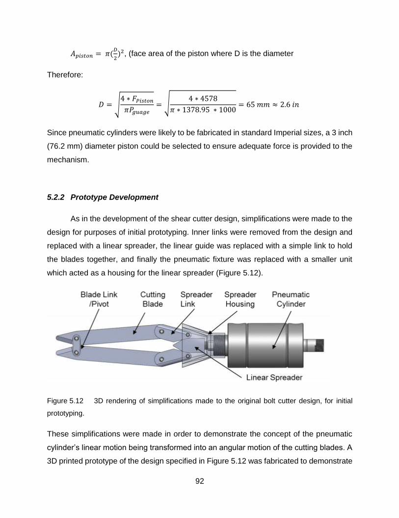
92
𝐴𝑝𝑖𝑠𝑡𝑜𝑛 = 𝜋(𝐷
2)2, (face area of the piston where D is the diameter
Therefore:
𝐷 = √4 ∗ 𝐹𝑃𝑖𝑠𝑡𝑜𝑛
𝜋𝑃𝑔𝑢𝑎𝑔𝑒= √
4 ∗ 4578
𝜋 ∗ 1378.95 ∗ 1000= 65 𝑚𝑚 ≈ 2.6 𝑖𝑛
Since pneumatic cylinders were likely to be fabricated in standard Imperial sizes, a 3 inch
(76.2 mm) diameter piston could be selected to ensure adequate force is provided to the
mechanism.
5.2.2 Prototype Development
As in the development of the shear cutter design, simplifications were made to the
design for purposes of initial prototyping. Inner links were removed from the design and
replaced with a linear spreader, the linear guide was replaced with a simple link to hold
the blades together, and finally the pneumatic fixture was replaced with a smaller unit
which acted as a housing for the linear spreader (Figure 5.12).
Figure 5.12 3D rendering of simplifications made to the original bolt cutter design, for initial
prototyping.
These simplifications were made in order to demonstrate the concept of the pneumatic
cylinder’s linear motion being transformed into an angular motion of the cutting blades. A
3D printed prototype of the design specified in Figure 5.12 was fabricated to demonstrate

93
the motion capabilities of the linkages connected with the piston. The sequence of
motions is captured in the three pictures (Figure 5.13, Figure 5.14 and Figure 5.15) which
did not include the pneumatic cylinder.

94
Figure 5.13 3D printed “proof of motion” prototype in starting position
Figure 5.14 Proof of motion prototype, showing in the position of mid-cut
Figure 5.15 Proof of motion prototype shown in final position at the end of the cut.

95
The prototype demonstrated that the cutting blades would behave in a manner
similar to the existing in-situ rod cutter, while requiring very little room to operate around
the spinal rod. However, this simplified version did not attempt to demonstrate the
mechanical advantage of the bolt cutter design. This would require precision manufacture
of the components of the bolt cutter design using medical grade stainless steels or
equivalent materials such that realistic forces could be applied.
Due to time constraints, no further work was done to develop this design. More
analysis, prototype development and prototype testing would be needed to complete the
implementation of this design.
5.3 Discussion
Both of the alternative designs were subjected to development as part of the
implementation. The shear cutter design was originally chosen as optimum in competition
with a bolt cutter design. After some simplifications, a prototype of the shear cutter design
was fabricated and its ability to cut large diameter (6.35 mm) cobalt alloy rods was
investigated. Unfortunately, after one successful cut was made, the prototype blades
fractured. While some design modifications might have allowed the shear cutter to
perform better, it was clear that it did not satisfy at least one of the constraints and had
perhaps been over-rated in the criteria scoring. Focus was shifted to the bolt cutter design.
This was a more conventional approach and its bolt-cutting technique did work for the
existing manual in-situ bolt cutters. A mechanism connecting a pneumatic cylinder to the
cutting blades was checked analytically for its mechanical advantage. A prototype was
made from a polymeric material using 3D printing to demonstrate the mechanism motion.
Unfortunately, there was not time for further development of this promising design.

96
6 Conclusions and Recommendations for Future Work
An engineering design process was applied to develop a new design for an in-situ
spinal rod cutter. Experimental work was performed to determine the technical
requirements of the design. Constraints and criteria were developed from a combination
of surgeon experience, experimental results and engineering experience. Two alternative
designs (shear cutter and bolt cutter) were presented and given scores based on the
criteria established. The shear cutter design was initially chosen as the optimum one but
it was abandoned after fracture problems in the prototype testing. The implementation of
the bolt cutter design was initiated. The conclusions of this thesis are as follows:
1. Shear cutting and bolt cutting techniques successfully cut the titanium, stainless steel
and cobalt chrome alloy rods, while the pipe cutting technique that was tested in
Chapter 3 did not successfully cut the cobalt chrome alloy rods.
2. When employing the bolt-cutting technique, it was found in Chapter 3 that the force
required to cut the rod increased with the rod diameter. However, the rod material
seemed to have little effect on the required cutting force, probably because the rods
all had similar similar yield strengths.
3. The cobalt chrome alloy rods, with maximum standardized diameter of 6.35 mm,
required the most force to cut. In Chapter 3, the shear cutting technique gave an
average cutting force of 26.08 ± 1.19 kN (average standard deviation) which was
slightly lower than the bolt-cutting technique force of 29.66 ± 1.29 kN.
4. The shear-cutting technique produced better cut end surfaces compared with the bolt-
cutting technique.
5. In order to ensure that any design developed, using either a shear or bolt-cutting
technique, would be able to cut all spinal rods, six standard deviations were added to
the experimentally determined averages. This factor of safety was chosen to ensure

97
that all spinal rods could be cut. A shear cutting design needed to provide a minimum
of 29.55 kN of cutting force while a bolt-cutting design should provide a minimum of
37.04 kN of cutting force.
6. Of the two design alternatives developed, the higher scoring design was the shear
cutting design. The bolt cutting design score was slightly lower than the shear cutting
design. A prototype of the shear cutting design was developed and tested, but it
fractured upon initial testing. The likely cause of this fracture was material selection,
friction and component sizing. Rather than redesign this alternative, the second
alternative design was developed.
7. A mechanical advantage of 8.17 was identified for the bolt cutter mechanism and a 3
inch (76.2 mm) diameter pneumatic cylinder was sized to meet the force requirements
necessary to cut rods using the bolt cutter design.
8. Due to time constraints, the fabrication and testing of the bolt cutting design alternative
was not performed. A 3D printed model was used to demonstrate the main mechanism
kinematics. The bolt cutting design shows optimistic potential for further development.
The development of the selected bolt cutting design did not reach a final product-
readiness stage, but future work should be performed to test and iterate upon the design
developed. It was considered likely that in this future work some of the design criteria
would be modified and a design evolution would occur. The following recommendations
are made for furthering this work.
1. Optimization of the bolt cutter linkage lengths and leverage points should be
performed with the intent to maximize the mechanical advantage these links provide.
2. Finite element analysis should be performed to optimize the sizing of the design
components. This could help to reduce the overall weight and size of the design, which
would improve its performance.

98
3. Safety of operating the designed cutter should be addressed because the current state
of the design had pinching points that would be a hazard in the operation of the cutter.
4. Ergonomics and marketing are aspects that should eventually be considered.
Since the engineering design process is an iterative process which results in the
evolution of the design, only immediate and milestone based recommendations can be
made at the present stage. Furthering the development of this in-situ rod cutter will reveal
more aspects of design which will need to be considered. The work presented in this
thesis provides a researched foundation for the development of an in-situ spinal rod
cutter.

99
Letter of Copyright Permission

100

101
102

103

104
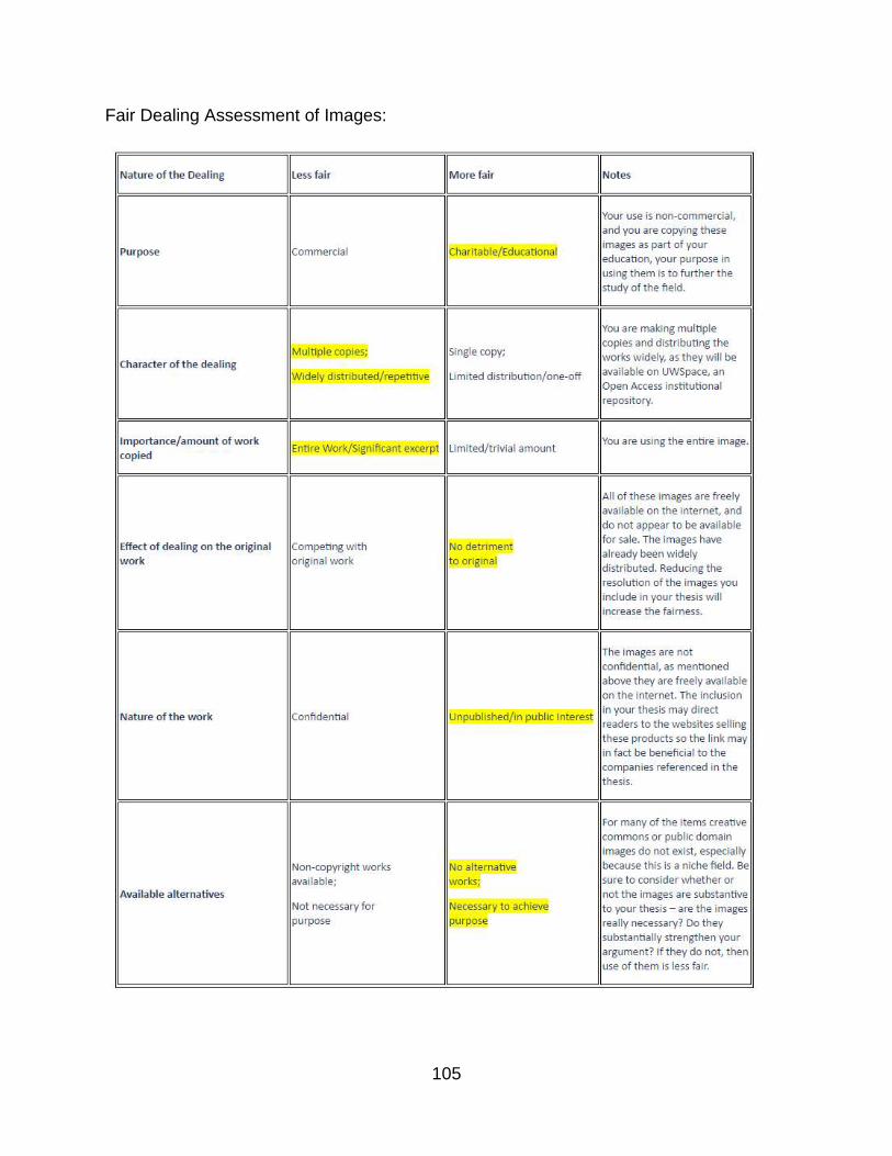
105
Fair Dealing Assessment of Images:
106
References
AAOS American Academy of Orthopaedic Surgeons. (2010, May 01). Congenital
Scoliosis Retrieved July 27, 2017, from
http://orthoinfo.aaos.org/topic.cfm?topic=A00576
Acaroglu, E., Yavuz, A.C, et al. (2016) A decision analysis to identify the ideal treatment
for adult spinal deformity: is surgery better than non-surgical treatment in improving
health-related quality of life and decreasing the disease burden?. European Spine
Journal 25(8):2390-2400
ASTRA Revision Spine System. (n.d.). Retrieved July 27, 2017, from
http://www.spinecraft.com/astra-revision-spine-system.html
Aylott, C. E., Hassan, K., Mcnally, D., & Webb, J. K. (2006). Intraoperative pulmonary
embolism of Harrington rod during spinal surgery: the potential dangers of rod cutting.
European Spine Journal, 15(12), 1853-1857.
AZO Materials (23 Mar. 2017). AISI 4140 Alloy Steel (UNS G41400). Retrieved July 27
2017, from, http://www.azom.com/article.aspx?ArticleID=6769
Berdishevsky, H., Lebel, V. A., Bettany-Saltikov, J., Rigo, M., Lebel, A., Hennes, A., …
Durmala, J. (2016). Physiotherapy scoliosis-specific exercises – a comprehensive
review of seven major schools. Scoliosis and Spinal Disorders, 11(1).
Betts, J. G., Desaix, P., Johnson, E., Johnson, J. E., Korol, O., Kruse, D., … Young, K.
A. (2016). Anatomy & physiology. Houston, TX: OpenStax College, Rice University.
Bradshaw Medical OEM Orthopedic and Spinal Instruments. Retrieved July 27, 2017,
from http://www.bradshaw-medical.com/products/rod-manipulation/tabletop-rod-cutter/
Breitling, J., Chernauskas, V., Taupin, E., & Altan, T. (1997). Precision shearing of
billets—special equipment and process simulation. Journal of Materials Processing
Technology, 71(1), 119-125.

107
Boos, N., & Aebi, M. (2008). Spinal disorders fundamentals of diagnosis and treatment.
Berlin, Heidelberg: Springer-Verlag Berlin Heidelberg.
Boston Childrens Hospital. (n.d.). Scoliosis in Children. Retrieved July 27, 2017, from
http://www.childrenshospital.org/conditions-and-treatments/conditions/scoliosis
Calendar 2015. (2015). Retrieved July 27, 2017, from http://calendariu.com/
Canadian Tire Mastercraft 1/8 to 1-1/8-in. Tube Cutter. (n.d.) Retrieved August 22,
2017, from http://www.canadiantire.ca/en/pdp/mastercraft-1-8-to-1-1-8-in-tube-cutter-
0585010p.html
Colorado Comprehensive Spine Institute. (n.d.). Retrieved July 27, 2017, from
http://www.coloradospineinstitute.com/
DePuy Expedium 4.5 System (n.d.). Retrieved July 27, 2017, from
https://www.depuysynthes.com/hcp/spine/products/qs/EXPEDIUM-4-5-System
Foley, K. T., Gupta, S. K., Justis, J. R., & Sherman, M. C. (2001). Percutaneous pedicle
screw fixation of the lumbar spine. Neurosurgical Focus, 10(4), 1–9.
Giudici, F., Galbusera, F., Zagra, A., Wilke, H.-J., Archetti, M., & Scaramuzzo, L. (2017).
Determinants of the biomechanical and radiological outcome of surgical correction of
adolescent idiopathic scoliosis surgery: the role of rod properties and patient
characteristics. European Spine Journal.
Gkiokas, A., Hadzimichalis, S., Vasiliadis, E., Katsalouli, M., & Kannas, G. (2006). Painful
rib hump: a new clinical sign for detecting intraspinal rib displacement in scoliosis due to
neurofibromatosis. Scoliosis, 1(1).
Grant JP, Oxland TR, Dvorak MF, Fisher CG (2002) The effects of bone density and
disc degeneration on the structural property distributions in the lower lumbar vertebral
endplates. J Orthopedic Research, 20 (5), 1115
Good, CR. (2010). Evolution in the Treatment of Spinal Deformity and Spinal
Instrumentation. Spinal Research Foundation.

108
Guo X, Chau WW, Chan YL, Cheng JC (2003) Relative anterior spinal overgrowth in
adolescent idiopathic scoliosis. Results of disproportionate endochondral-membranous
bone growth. J Bone Joint Surg Br 85:1026 – 1031-1120.
Holmed (n.d.) Rod Instruments Ratcheting Rod Cutters. Retrieved August 24th 2017
http://www.holmed.net/prd_img/ri_4.html
Hoppe, S., & Keel, M. J. B. (2016). Pedicle screw augmentation in osteoporotic spine:
indications, limitations and technical aspects. European Journal of Trauma and
Emergency Surgery, 43(1), 3–8.
IMTech (n.d.) Lospa IS Screw System. Retrieved July 27 2017
http://imtec.mn/en/product/screw-system/
Lamerain, M., Bachy, M., Delpont, M., Kabbaj, R., Mary, P., & Vialle, R. (2014). CoCr
rods provide better frontal correction of adolescent idiopathic scoliosis treated by all-
pedicle screw fixation. European Spine Journal, 23(6), 1190-1196.
Lenox, L. (1999). Surgical rod cutter. US 5988027 A.
McLachlin, S. D. (2008), Design and Development of In Vitro Tools to assess fixation and
motion of the spine, London, ON (MASc thesis).
Mayo Clinic (2014, June 06). Kyphosis: Rounded upper back can be mild or painful.
Retrieved July 27, 2017, from http://www.mayoclinic.org/diseases-
conditions/kyphosis/basics/definition/CON-20026732
Medical Apparatus (n.d.). Gallery of Medical Devices - Neck and Cervical Spine
continued. Retrieved July 27, 2017, from
http://medapparatus.com/Gallery/Gallery_NeckSpine_Page2.html
Medical Dictionary (n.d.) Biocompatible. Retrieved July 27, 2017, from http://medical-
dictionary.thefreedictionary.com/biocompatible
Medscape (n.d.) Idiopathic Scoliosis. (2017, May 2). Retrieved August 22, 2017, from
http://emedicine.medscape.com/article/1265794-overview
109
Mohan L. A., Das K., (2003) History of surgery for the correction of spinal deformity.
Neurosurgical Focus 14(1):1-5
Netter, F. H. (2014). Atlas of human anatomy. Philadelphia, PA: W. B. Saunders Co.
Noshchenko, A., Xianfeng, Y., Armour, G. A., Baldini, T., Patel, V. V., Ayers, R., & Burger,
E. (2011). Evaluation of spinal instrumentation rod bending characteristics for in-situ
contouring. Journal of Biomedical Materials Research Part B: Applied Biomaterials,
98B(1), 192-200
Oded H., Alon F., Barak G., Harel A., et al., (2004) Association between body mass
index, body height, and the prevalence of spinal deformities. The Spine Journal
14:1581–1587
Ozgur, B., Benzel, E. C., et al. (2009). Minimally invasive spine surgery: A practical
guide to anatomy and techniques. Springer Publishing.
Pain Management L.A. (2013, January 22). Physical Therapy. Retrieved July 27, 2017,
from https://www.painmanagementlosangeles.com/physical-therapy.html
Patel, V. V., Patel, A., Harrop, J. S., & Burger, E. (2014). Spine Surgery Basics. Berlin,
Heidelberg: Springer Berlin Heidelberg.
Restore Orthopedics. (n.d.). BUILDING THE DOCTOR/PATIENT RELATIONSHIP.
Retrieved July 27, 2017, from http://restoreorthopedics.com/
SECO/WARWICK Corp, comp. Heat Treating Data Book. 10th ed. Meadville:
SECO/Warwick Corporation, 2011.
Silverjonny. (2006). Wiki post-op.jpg. Wikimedia Commons. photograph, London, UK.
Retrieved from https://commons.wikimedia.org/wiki/File:Wiki_post-op.jpg
Slivka, M. A., Fan, Y. K., & Eck, J. C. (2013). The Effect of Contouring on Fatigue
Strength of Spinal Rods: Is it Okay to Re-bend and Which Materials Are Best? Spine
Deformity, 1(6), 395-400.
Spine Centre. (n.d.). Idiopathic Scoliosis. Retrieved July 27, 2017, from
http://spinecenter.ucla.edu/body.cfm?id=160&iirf_redirect=

110
Spine-Health Peter F. Ullrich, Jr., MD, Orthopedic Surgeon (retired). (n.d.). Pedicle
Screws for Spine Fusion. Retrieved July 27, 2017, from https://www.spine-
health.com/treatment/spinal-fusion/pedicle-screws-spine-fusion
University of Wisconsin-Madison College of Engineering (2016). Retrieved July 27,
2017, from https://bmedesign.engr.wisc.edu/projects/f16/spinal_rod_cutter/
Winter RB., (1977) Congenital kyphosis. Clinical Orthop and Related Research 128:26-
32
Yoshihara, H. (2013). Rods in spinal surgery: a review of the literature. The Spine
Journal, 13, 1350-1358.
Zimmer Spine | Sequoia Pedicle Screw Systems, Pedicle Screws, Spine Surgery
Instruments (n.d.). Retrieved July 24, 2017, from http://www.zimmer.nl/medical-
professionals/products/spine/sequoia-pedicle-screw-system.html