Embed Size (px)
Citation preview

SNAP RING JOINT
DESIGN DATA
TECHNICAL
COMBINING INNOVATION AND WORLD CLASS ENGINEERING

SNAP RING JOINT DESIGN DATA
CO
NTEN
TS
SECTION PAGE
IMPORTANT NOTICE 2
GLOSSARY 3
1. PRODUCT OVERVIEW 4
2. DESIGN BASIS 5
3. COUPLING DESIGN 5
4. COUPLING INSTALLATION 5
5. PRODUCT TESTING 6
6. PRODUCT RANGE 6
7. CORROSION CONSIDERATIONS 6
8. DOCUMENTATION 6
9. SRJ GENERAL ASSEMBLY 7
10. DESIGN METHOD & CROSS SECTIONS 8
11. LLOYD’S REGISTER TYPE APPROVAL 9
Page 1 of 10

SNAP RING JOINT INSTALLATION PROCEDURESSNAP RING JOINT DESIGN DATA
IMPO
RTA
NT N
OTIC
E
The technical, performance data, specifications,dimensions, and all other information published inthis document supersede all previously publishedinformation.
All data contained herein is subject to changewithout notice.
The information given in the following pages isintended as a general guide to the design andinstallation of the SRJ pipe coupling. It is notintended as a substitute for competent,professional advice, which should always be soughtin the design of any piping system. Good pipingpractice should always prevail and recommendeddesign pressures, temperatures, tolerances andloads should never be exceeded.
Special conditions often exist for which theinformation given here is not specifically suited andspecialist engineering advice should be obtained.
While every effort has been made to ensure itsaccuracy, Snap Ring Joint Limited make no expressor implied warranty of any kind in respect of theinformation contained in this technical designdocument or the materials referred to herein. Anyperson making use of the information containedhere does so entirely at their own risk and assumesany and all liability resulting from such use.
The information contained within this sectionapplies specifically to Snap Ring Joint Limitedproducts only.
© 2017 Snap Ring Joint LimitedNo part of this document may be reproduced,stored or transmitted, in any form or by anymeans, electronic, mechanical, photocopying,recording or otherwise, without prior permission.
Page 2 of 10

SNAP RING JOINT DESIGN DATA
GLOSSARY OF TERMS
The following abbreviations are used in this document:
O&G Oil and GasOD Pipe outside diameterNB Nominal boreA350 LF2 A general carbon steel usually supplied in a normalised and tempered or
quenched condition.HNBR Hydrogenated Nitrile Butadiene Rubberpsi Pounds per square inchPCD Pitch circle diameter
GLOSSARY OF STANDARDS
The following standards are used in this document:
API.5L Specification for Line Pipe
ASME B31.1 Specification for Power Piping ASME Codes for Pressure Piping, B31
ASME B31.3 Specification for Process Piping ASME Codes for Pressure Piping, B31
ASME B31.4 Specification for Pipeline Transportation Systems for Liquids and Slurries ASME Codes for Pressure Piping, B31
ASME B31.8 Specification for Gas Transmission and Distribution Piping Systems ASME Codes for Pressure Piping, B31
ASME B31.9 Specification for Building Services Piping ASME Codes for Pressure Piping, B31
ASTM A694 Standard Specification for Carbon and Alloy Steel Forgings for Pipe Flanges, Fittings, Valves and Parts for High-Pressure Transmission Service
BS EN 166 : Specifications for Personal Protection Equipment
BS EN 397:1995 Industrial safety helmets
EN10204 3.1 Metallic products. Types of inspection documents
IACS P2 Requirements concerning pipes and pressure vessels
ISO 19921:2005(E) Ships and marine technology – Fire resistance of metallic pipe components with resilient and elastomeric seals - Test methods
ISO 19922:2005(E) Ships and marine technology – Fire resistance of metallic pipe components with resilient and elastomeric seals – Requirements imposed on the test bench
NACE MR01-75 Petroleum and natural gas industries – Materials for use in H2S-containing environments in oil and gas production
GLO
SSA
RY
Page 3 of 10

SNAP RING JOINT DESIGN DATA
1. PRODUCT OVERVIEW
The SRJ coupling is a weldless mechanicalconnector that has been designed to replacewelding and/or other mechanical systems.
The design of the connector complies with theASME piping/pipeline codes – B31.1, B31.3, B31.4,B31.8 and B31.9
The SRJ coupling comprises a single sleeve thatspans the pipes being connected, which houses thecouplings’ sealing and gripping elements.
The couplings’ grip is provided by retaining wireswhich locate into grooves in the body of theconnector and corresponding grooves machinedinto the outside diameter of the pipe.
The sealing system comprises high integrityelastomeric seals which are currently available inHNBR (Nitrile) or Viton, depending upon theapplication. The HNBR seal is based upon casingsealing technology and is energised duringcoupling installation. The Viton seal is of a pressureenergised lip seal design.
Please refer to section 9 for the general assembly.
The selection of the seal is dependent upon thepipe content and the operating temperature. Thecurrent HNBR seal operating temperature isbetween -29 & 160 OC. The Viton seals operating
temperatures is -20 and 200OC.
PRO
DU
CT O
VER
VIE
W
The pipe in the area of the seals needs to bemachined to ensure the seal performs as specified.The twin sealed version allows the coupling to beexternally tested thus verifying joint integrity priorto pressuring the system going live. A metal sealedunit is currently under development
The SRJ coupling is unstressed (i.e. non-bolted)and relies on internal pipe pressure to load theretaining wires and energize the seals. This uniquedesign allows the coupling to be compact andlightweight without the need to incorporate boltsfor seal energisation.
The SRJ therefore offers many benefits over otherpipe connection methods:
• Ability to withstand high internal pressures• Speed of installation• No welding required for installation• No bolting required for installation• Lightweight• Compact• Cold works only
RETAINING WIRES
FS CASING SEAL
Page 4 of 10

SNAP RING JOINT DESIGN DATA
2. DESIGN BASIS
The basic design of the connector complies withthe ASME pressure piping – B31.1, B31.3. B31.4,B31.8 and B31.9 with additional load/applicationrequirements being documented in the projectinformation sheet contained within the Appendix ofthe accompanying Coupling InstallationProcedures.
This data obtained from the customer ensures thatthe design not only meets the requirements of thecodes but will be fit for its intended purpose.
The coupling is classified as an un-listedcomponent in accordance with the specificationscontained within ASME B31.3 and as suchcompliance to the code is as listed in paragraph304.7.2
Code compliance is through proof testing.
Proof testing of a range of connector’srepresentative of the size range being registered(up to 16” NB) has been conducted in accordancewith the IACS P2 requirements, witnessed byLloyds as part of their Type Approval program.
The connector materials and the level of allowablestress used in the design is based upon table A-1of ASME B31.3. Allowable design stresses are usedfor the couplings main body but the retaining wiresutilise a higher factor of safety with the allowabledesign stress at operating pressure being equal to15% of the minimum ultimate shear strength ofeach of the retaining wires. (Note – the standardconnector has 2 retaining wires fitted per side).
The design pressure used in the couplings designis based upon paragraph 304.1.2 of ASME B31.3Straight Pipe under Internal Pressure
3. COUPLING DESIGN
The coupling, as previously stated is designed tocomply with the applicable pipe design codes andhas been designed so that it is not the weak link inthe system as it is more than capable ofwithstanding internal pipe pressures up to pipeburst.
The depth of groove in the pipe is calculated toensure that it does not impact on the pressurecontaining capability of the pipe or its safeoperation.
When grooves are machined into the pipe as partof the assembly process, the pipe is thenconsidered to be de-rated. Therefore, the pressure
rating of the entire assembly should beconsidered rather than the point at which thegrooves have been added but not the coupling.The pipe will never be subject to pressure withinthe grooves without the coupling. Thecoupling/pipe assembly is an ‘UnlistedComponent’ in ASME B31.3 (see paragraph304.7.2), that has been substantiated by adetailed stress analysis using finite elements. Thedesign has also been substantiated by extensiveexperimental testing (in accordance with IACS P2).
The depth of groove in the pipe is determined byseveral factors:
1. The longitudinal stress in the pipe, under thegroove does not exceed 20,000 psi(API.5L.grade B) at design pressure.
2. The pipe with the coupling installed is capableof withstanding the tensile pull test specified inthe IACS P2 test regime. This states that thecoupling must withstand a tensile load equal tothe hydrostatic end force generated by thedesign pressure in addition to the couplingbeing pressurized to its design pressure.
The coupling sleeve spans the pipe ends beingconnected which provides stiffness to theconnection point. This ensures that the bendingcapacity of the pipe is maintained whether thesystem is pressurized or not. Under bending, themoment is resisted by the 2 sets of retaining wireslocated on either side of the connection pointwhich prevents excessive pipe movement in thearea of the seals.
4. COUPLING INSTALLATION
The coupling is installed by trained and competentpersonnel and can be used for both newconstruction and pipe repairs. To prepare thepipes being connected standard clamshell type insitu machining tools are utilized which have thecapability to cut the pipe, prepare the ends and tocut the retaining wire groves.
Section 10 of the accompanying CouplingInstallation Procedures shows the complete pipemachining specification and provides a step bystep guide to the products installation andremoval.
DESIG
N B
ASIS
Page 5 of 10

SNAP RING JOINT DESIGN DATA
5. PRODUCT TESTING
The coupling has successfully undergone a seriesof load/performance tests, in accordance with anindustry recognised test program (IACS). Theresults of which have enabled Lloyd’s to issue aType Approval certificate covering the coupling’suse on hydrocarbon systems in sizes up to 16”. Anoverview of the tests undertaken is shown insection 11.
6. PRODUCT RANGE
The SRJ can also be supplied in the followingvariants:
• A blind flange, which is ideal when capping pipework to facilitate a pressure test, thus avoidingthe cost and time involved in welding a domeend to the pipe. If a pipe end has been fittedwith a SRJ blind post-test the unit can beremoved and the main pipe connection madeby an SRJ coupling utilizing the same pipe endpreparation.
• A Flange Transition unit, this product connects abare pipe end to a pre flanged component,ideal for connecting to flanged pipingcomponents.
• A twin sealed unit which allows the connectorssealing integrity to be checked before thepiping system is hydro tested.
• The SRJ system can also be incorporated intoReducers, Tees and Elbows.
7. CORROSION CONSIDERATIONS
The SRJ connector has been designed to ensurethat any corrosion that occurs within the body ofthe connector will be minimal and will not impactthe unit’s performance during its operational life.
The construction materials of the connector areselected to be compatible with the process fluidand pipe i.e. ASTM A694/A350 LF2 and controlledin accordance with NACE MR01-75 if sour service isrequired.
A simple low pressure environmental seal fitted atthe end of the connector ensures the cavitybetween the pipes/coupling and retaining wire isprotected from the environment and a facility ispresent to inject a suitable corrosion inhibitor.
PRO
DU
CT T
ESTIN
G A
ND
RA
NG
E
A small gap exists between the pipe ends so thatthe inner bore of the connector, up to the radialseals is process wetted, however, the pipe media inthis area is not constantly replenished due to thesize of the annulus and minimal pipe end gap. Theseating stress of the seals is high enough toprevent media from passing beneath the seals,which mitigates corrosion in the area under theseals.
The external walls of the connector are coated withindustry standard epoxy coatings to customerspecifications.
8. DOCUMENTATION
The coupling as standard is supplied with acertificate of conformity, chemical and mechanicalmaterial certification to EN10204 3.1 along with apressure test certificate covering the factoryacceptance test. 3rd party verification ofmaterials/testing can be supplied.
Page 6 of 10
SNAP RING JOINT DESIGN DATA
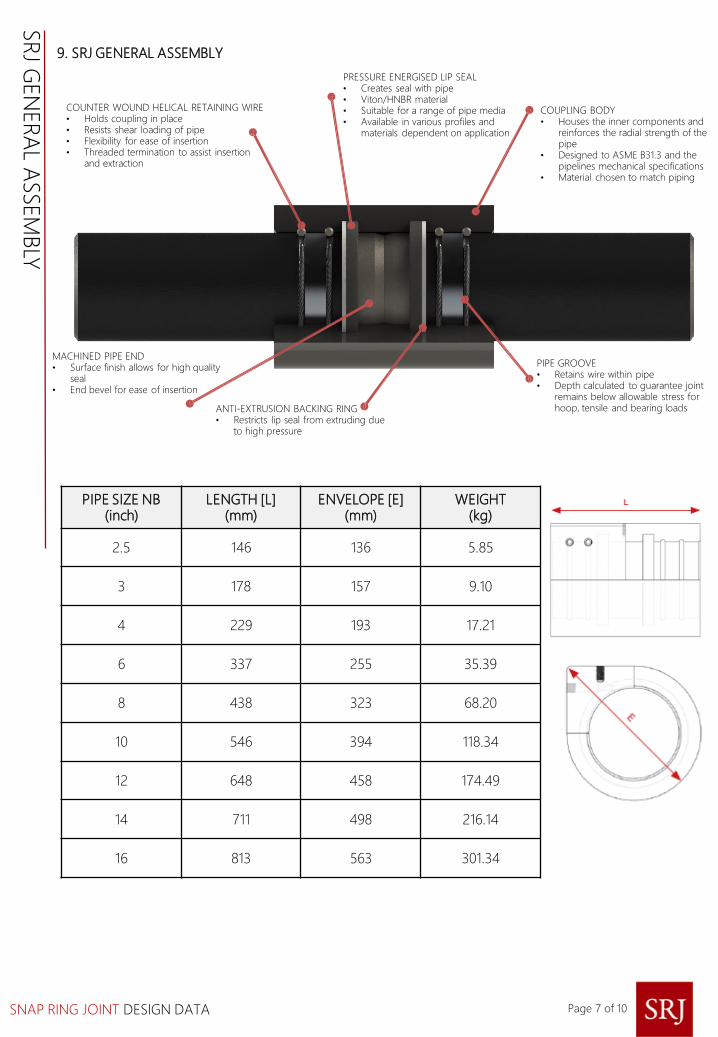
9. SRJ GENERAL ASSEMBLY
COUNTER WOUND HELICAL RETAINING WIRE• Holds coupling in place• Resists shear loading of pipe• Flexibility for ease of insertion• Threaded termination to assist insertion
and extraction
PRESSURE ENERGISED LIP SEAL• Creates seal with pipe• Viton/HNBR material• Suitable for a range of pipe media• Available in various profiles and
materials dependent on application
COUPLING BODY• Houses the inner components and
reinforces the radial strength of the pipe
• Designed to ASME B31.3 and the pipelines mechanical specifications
• Material chosen to match piping
MACHINED PIPE END• Surface finish allows for high quality
seal• End bevel for ease of insertion
ANTI-EXTRUSION BACKING RING• Restricts lip seal from extruding due
to high pressure
PIPE GROOVE• Retains wire within pipe• Depth calculated to guarantee joint
remains below allowable stress for hoop, tensile and bearing loads
PIPE SIZE NB (inch)
LENGTH [L](mm)
ENVELOPE [E] (mm)
WEIGHT(kg)
2.5 146 136 5.85
3 178 157 9.10
4 229 193 17.21
6 337 255 35.39
8 438 323 68.20
10 546 394 118.34
12 648 458 174.49
14 711 498 216.14
16 813 563 301.34
SR
J GEN
ER
AL A
SSEM
BLY
Page 7 of 10
SNAP RING JOINT DESIGN DATA
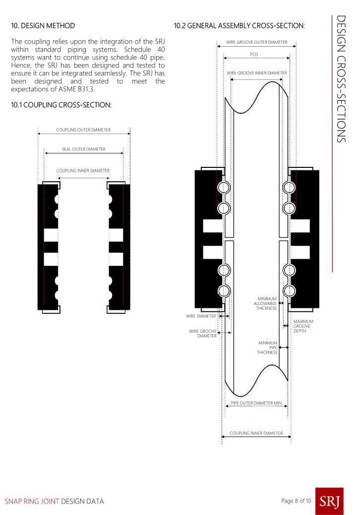
WIRE GROOVE OUTER DIAMETER
PCD
WIRE GROOVE INNER DIAMETER
MINIMUM ALLOWABLE
THICKNESS
MAXIMUMGROOVEDEPTH
MINIMUM PIPE
THICKNESS
WIRE DIAMETER
WIRE GROOVE DIAMETER
PIPE OUTER DIAMETER MIN.
COUPLING INNER DIAMETER.
COUPLING OUTER DIAMETER
SEAL OUTER DIAMETER
COUPLING INNER DIAMETER
10. DESIGN METHOD
The coupling relies upon the integration of the SRJwithin standard piping systems. Schedule 40systems want to continue using schedule 40 pipe.Hence, the SRJ has been designed and tested toensure it can be integrated seamlessly. The SRJ hasbeen designed and tested to meet theexpectations of ASME B31.3.
10.1 COUPLING CROSS-SECTION:
DESIG
N C
RO
SS-S
EC
TIO
NS
10.2 GENERAL ASSEMBLY CROSS-SECTION:
Page 8 of 10

SNAP RING JOINT DESIGN DATA
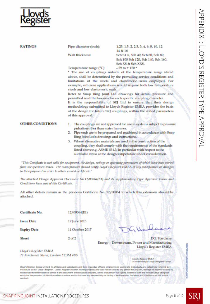
11. LLOYD’S REGISTER TYPE APPROVAL
The SRJ has completed a witnessed test regimefrom IACS P2, a full assessment of the design basisand a manufacturing audit, in order to gain LloydsRegister Type Approval for use in a variety ofapplications requiring high pressure fluidtransmission in O&G, utilities, chemicals, processingand desalination. The manufacturer’s of the SRJcurrently includes John Mayes Engineering andMussett Engineering in the UK, however themanufacturing can be located anywhere that hasundergone the required audit by Lloyds.
The connector is fully compliant with ASME B31.1(2012), ASME B31.3 (2012), ASME B31.4, ASME B31.8(2012), ASME B31.9 (2011) and IACS P2 (2008).
Three sizes of connector were selected for testing:the SRJ 2 ½" SCH40, the SRJ 4" SCH40 and the SRJ8" SCH40. The design pressure for each OD is2603 psi, 1914 psi and 3967 psi respectively. Thiswas to prove and agree a principal that can beapplied to sizes in this range. Interpolation from 11/4" to 16" OD is allowed.
11.1 REPEATED ASSEMBLY TEST
This demonstrates that the SRJ can bedisassembled for routine checks when requiredand still perform at a high level once reinstalled.
The SRJ was dismantled and reassembled ten timesin accordance with the manufacturer's installationmanual, and then subjected to a tightness test. Thetest was successfully conducted.
11.2 TIGHTNESS TEST
This demonstrates the performance of the SRJ atdesign pressure.
Without being longitudinally restrained, the SRJwas connected to the pipe, filled with test fluid andde-aerated. Pressure inside the SRJ assembly wasincreased to 1.5 times design pressure andmaintained for five minutes. No leakage or drop inpressure was recorded. All three SRJ samplespassed the tightness test.
11.3 BURST PRESSURE TEST
This demonstrates the SRJ’s ability to withstandpressure surges in the pipeline by taking theconnector to its yield point.
The SRJ assembly had to withstand a burstpressure of four times the design pressure. Theassembly must not be restrained
longitudinally and the pressure inside wasprogressively increased, then held for at least fiveminutes with no deformation, leakage or cracking.The test is based on IACs standards, which coverpressure-containing equipment and is thereforecompliant with the European Pressure EquipmentDirective (EPD). The 8” SRJ passed the test and itspressure-withstanding ability was successfullytested to nearly 17,000 psi.
11.4 EXTERNAL PRESSURE TEST
This demonstrates the performance of the SRJ in ahigh external pressure environment similar to avacuum service or subsea.
An external pressure chamber was assembledaround the connection, then filled with water andbled of all air. The pressure was increased inincrements until it achieved 80% of the pipe bendyield stress and held for five minutes. Once 80%was achieved, the pressure was increased until theconnection failed or the pipe collapsed. The 2 ½",4" and 8" samples passed this test.
11.5 VIBRATION (FATIGUE) TEST
This test demonstrates SRJ's ability to withstandfatigue, which is likely to occur due to vibrations,under service conditions.
The SRJ assembly must not be restrainedlongitudinally. Two lengths of pipe were connectedby the SRJ, with one pipe end rigidly fixed and theother fitted to the vibrating element on a cantilevertype test rig. The assembly was filled with test fluid,de-aerated and pressurised to the design pressureof the SRJ. The test meets the requirements IACSP2 Rev.2 2001 (Rules for piping design,construction and testing) and all three SRJ samplespassed.
11.6 PULL-OUT TEST
This demonstrates SRJ's ability to deal with axialloads likely to be encountered in service, withoutthe connecting pipe becoming detached. Pipelengths were fitted to each end of the SRJ and theassembly was pressurised to design pressure, inorder to impose an axial load calculated accordingto a formula based on pipe OD and designpressure.
The load was maintained for five minutes andpressure monitored. There was no drop inpressure, signs of leakage, damage or movementbetween the SRJ and the connecting pipe. All threesamples passed this test with no movementrecorded.
LLOYD
’ S R
EG
ISTER
TYPE A
PPRO
VA
L
Page 9 of 10

SNAP RING JOINT DESIGN DATA
The assemblies were then further tested (at therequest of SRJ) so that whilst under designpressure, the pipes were assembled into a tensionrig and the assembly axially loaded until breakageoccurred. The 2 ½" sample demonstrated a breakload of 30.39 tonnes, the 4" sample a break load of66.5 tonnes and the 8" sample a break load of418.18 tonnes, but without failure. The test on the8" sample was stopped at that point because thetest house insurance would not have covereddamage to the test rig at additional pressure.
11.7 FIRE ENDURANCE TEST
ISO 19921:2005(E) and ISO 19922:2005(E): Shipsand marine technology- fire resistance of metallicpipe components with resilient and elastomericseals.
The SRJ and connecting pipes were subjected to an800°C flame for thirty minutes, with an 80°C inputtemperature for the water flowing through theassembly and a maximum output temperature of85°C. The velocity of flow had to at least 0.1 m
3per
second and the water pressure at 5 bar. Once theSRJ assembly was returned to ambienttemperature, a five minute pressure test wasconducted. All three samples passed the test.
11.8 COMBINED BENDING/PRESSURE TEST
This test demonstrated the SRJ's ability towithstand both axial loads and bending momentsapplied simultaneously. The SRJ was taken to 90%of the yield stress of the pipe material first bybending alone and then by combined bending andinternal pressure. It was subjected to the requiredbending load while no internal pressure wasapplied and held for five minutes before thebending load was relaxed.
Since there was no residual deformation, the SRJwas pressurised to the design pressure andisolated. A reduced bending moment was thenapplied so that the combined stress in the wall ofthe pipe (axial stress from the internal pressurecoupled with the bending stress) was equal to 90%of the yield stress of the pipe material.
This combined bending and pressure was held fora period of five minutes before the bending loadwas relaxed and the pressure relieved. During thetest, the pressure was monitored and aftercompletion of the test, there was to be no leakageor movement between the SRJ and the connectingpipes. The test was repeated but without internalpressure, to ascertain its strength withoutsupporting internal pressure. All three SRJ samplespassed the test.
LLOYD
’ S R
EG
ISTER
TYPE A
PPRO
VA
L
Page 10 of 10
A copy of the Certificate is included in theAppendix to the accompanying CouplingInstallation Procedures.

SNAP RING JOINT DESIGN DATA
BLANK PAGE

SNAP RING JOINT
INSTALLATION PROCEDURES
COUPLING
COMBINING INNOVATION AND WORLD CLASS ENGINEERING

SNAP RING JOINT INSTALLATION PROCEDURES
SECTION PAGE
1. DOCUMENT SCOPE 2
2. SAFETY 2
3. HANDLING 2
4. COUPLING DESCRIPTION 2
5. COUPLING SPECIFICATION 3
6. PIPE SPECIFICATION – PREPARATION 3
7. COUPLING INSTALLATION 3
8. COUPLING REMOVAL 4
9. DOCUMENTATION 4
10. PIPE PREPARATION 6
APPENDIX I – LLOYD’S REGISTER TYPE APPROVAL 7
APPENDIX II – PROJECT INFORMATION SHEET 9
Page 1 of 10
CO
NTEN
TS

SNAP RING JOINT INSTALLATION PROCEDURES
1. DOCUMENT SCOPE
The following procedures cover the installation ofthe coupling.
The procedure specifically covers:
• The specification of the pipe preparationrequired to allow the SRJ coupling to becorrectly installed.
• Detailed information covering the installationand removal of the SRJ coupling.
It is the responsibility of the installation contractorto correctly prepare the pipe ends either in afabrication facility or by use of portable in-situmachining equipment that is capable of achievingthe required specification.
2. SAFETYThe coupling must be installed and the pipesprepared by competent personnel who are trainedin the safe use of installation equipment and whoare capable of working in a safe and propermanner.
Please read and fully understand these proceduresbefore attempting to install any SRJ coupling.
PERSONAL PROTECTIVE EQUIPMENT (PPE).
Minimum PPE safety requirements are listed below,however site specific safety requirements andresults of risk assessments should be consideredprior to commencing work.
• Approved non slip safety boots with internalsteel toecap;
• Safety helmet approved to BS EN 397 : 1995;• Safety spectacles approved to BS EN 166 - 1F
minimum; and• Cut resistant safety gloves
A risk assessment of the SRJ coupling installationand application for which it is destined, must beundertaken prior to commencement of works, andrecommendations adopted that will mitigate anyrisk. It is mandatory that a work permit is obtainedstating that the line is depressurised and cleanbefore commencing any installation/pipepreparation work.
3. HANDLING
SRJ couplings can weigh more that therecommended maximum weight permitted to bemanually lifted. Therefore, always use appropriatelifting equipment and certified slings whenhandling the couplings. An eye bolt hole is locatedwithin the coupling which can be used by screwingin the correct eye bolt.
Ensure that all industry regulations and practicesare adhered to and ensure no one is allowed towork beneath suspended loads.
4. COUPLING DESCRIPTION
The SRJ coupling comprises three key elements:-
1. Pressure Containing SleeveThe sleeve is manufactured from a single pieceforging in materials that are compatible with thepipe content and spans the two pipe ends beingconnected.The inner periphery of the sleeve is machined toaccept the systems load retaining wires andsealing system.
2. Retaining WiresThe retaining wires are fed into the inner couplinggrooves, which align with grooves machined intothe pipes outer surface. The pipe groove depth iscalculated and verified by testing to ensure that thepipe’s pressure capacity is not reduced. Extensivetesting and design analysis has been undertakenwhich demonstrates that under pressure, the pipe’sstrength is not reduced due to the machinedgroove.
The wires are constructed from counter-woundstrands of high quality steel to ensure bothstrength and flexibility.
Once installed, the wires are locked into positionand a suitable corrosion inhibitor injected, whichmust be compatible with the elastomeric seals.
3. Sealing SystemThe sealing system is based upon high integrityelastomeric seals that seal onto the periphery ofthe pipe. Two types of seals are used, either aNitrile (HNBR) ‘Casing Seal’ which comprises asolid seal with built in metallic anti-extrusion ringsor a Viton Lip Seal. Please check the projectinformation sheet in Appendix I as to which typehas been supplied with the coupling.
The seals are initially energised during installationof the coupling, with the initial contact stress beingsufficient to initiate the sealing process.
Page 2 of 10
INSTA
LLA
TIO
N P
RO
CED
UR
ES
SNAP RING JOINT INSTALLATION PROCEDURES
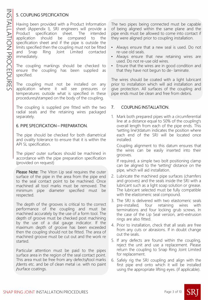
5. COUPLING SPECIFICATION
Having been provided with a Product Informationsheet (Appendix I), SRJ engineers will provide aProduct specification sheet. The intendedapplication should be compared to thespecification sheet and if the pipe is outside thelimits specified then the coupling must not be fittedand Snap Ring Joint Limited contactedimmediately.
The coupling markings should be checked toensure the coupling has been supplied asspecified.
The coupling must not be installed on anyapplication where it will see pressures ortemperatures outside what is specified in theseprocedures/stamped on the body of the coupling.
The coupling is supplied pre fitted with the tworadial seals and the retaining wires packagedseparately.
6. PIPE SPECIFICATION – PREPARATION.
The pipe should be checked for both diametricaland ovality tolerance to ensure that it is within theAPI 5L specification.
The pipes’ outer surfaces should be machined inaccordance with the pipe preparation specification(provided on request)
Please Note: The Viton Lip seal requires the outersurface of the pipe in the area from the pipe endto the seal contact point to be machined. Oncemachined all tool marks must be removed. Theminimum pipe diameter specified must berespected.
The depth of the grooves is critical to the correctperformance of the coupling and must bemachined accurately by the use of a form tool. Thedepth of groove must be checked post machiningby the use of a dial gauge indicator. If themaximum depth of groove has been exceededthen the coupling should not be fitted. The area ofmachined groove must be cut out and the work restarted.
Particular attention must be paid to the pipessurface area in the region of the seal contact point.This area must be free from any defects/tool marks/dents etc. and be of clean metal i.e. with no paint/surface coatings.
The two pipes being connected must be capableof being aligned within the same plane and thepipe ends must be allowed to come into contact ifthey were aligned prior to coupling installation.
• Always ensure that a new seal is used. Do notre-use old seals.
• Always ensure that new retaining wires areused. Do not re-use old wires.
• Ensure that the wires are in good condition andthat they have not begun to de- laminate.
The wires should be coated with a light lubricantprior to installation which will aid installation andgive protection. All surfaces of the coupling andpipe ends must be clean and free from debris.
7. COUPLING INSTALLATION.
1. Mark both prepared pipes with a circumferentialline at a distance equal to 50% of the coupling’soverall length from each of the pipe ends. This‘setting line’/datum indicates the position whereeach end of the SRJ will be located onceinstalled.
Coupling alignment to this datum ensures thatthe wires can be easily inserted into theirgrooves.
If required, a simple two bolt positioning clampcan be aligned to the ‘setting’ distance on thepipe, which will aid installation.
2. Lubricate the machined pipe surfaces (chamfersand grooves) and the seals inside the SRJ with alubricant such as a light soap solution or grease.The lubricant selected must be fully compatiblewith the elastomeric seal compound.
3. The SRJ is delivered with two elastomeric sealspre-installed, four retaining wires withterminations and four locking grub screws. Inthe case of the Lip Seal version, anti-extrusionrings are also fitted.
4. Prior to installation, check that all seals are freefrom any cuts or abrasions. If in doubt changeout the seals.
5. If any defects are found within the coupling,reject the unit and use a replacement. Pleasereturn the coupling to Snap Ring Joint Limitedfor replacement.
6. Safely rig the SRJ coupling and align with thefirst pipe end onto which it will be installedusing the appropriate lifting eyes. (if applicable).
Page 3 of 10
INSTA
LLA
TIO
N P
RO
CED
UR
ES

SNAP RING JOINT INSTALLATION PROCEDURES
7. The SRJ coupling can now be pushed over thepipe end until it aligns with the retaining clamp/setting line. For larger dimension couplings,
(i.e. over 6”OD) a hydraulically operated
installation tool is available.
8. Insert one of the two retaining wires into oneof the wire access holes in the side of the SRJsleeve that is adjacent to the pipe end. Whenjust the end of the wire with the termination isvisible, screw the insertion tool into thetermination (which has a female thread) andpush into the access hole until the wire is nolonger visible, and reaches a stopping point.Close the entrance of the wire access hole witha locking grub screw.
9. The wire should be easy to insert but in theevent that the wire is difficult to insert thecoupling’s position should be slightly adjustedas it is likely that the coupling/pipe grooves arenot in correct alignment. Repeat this processfor the second wire on thesame side of the SRJ sleeve
10. Align the second pipe and pull into the openend of the coupling by means of suitablerigging equipment / SRJ handling tools.
11. Once the second pipe is completely pulledwithin the coupling (pipe ends in contact) theretaining wires should be inserted as above.
In the event that the coupling is fitted with greasenipples, then at this stage the corrosion inhibitorcan be injected between the coupling/pipe annulusaround the retaining wires.
8. COUPLING REMOVAL
Prior to removing an SRJ coupling a permit to workmust be obtained stating that the line is safe towork on. Please verify that the line is depressurisedand vented.
Suitable rigging / lifting equipment should be usedif the couplings weight is about that which can besafely manually handled. Attach the riggingequipment to the eye bolt hole located in thecoupling.
1. Remove the grub screws protecting theretaining wires.
2. Attach the retaining wire reparation tool byscrewing in clockwise (making sure not todamage any of the mating threads).
3. Rotate and pull the retaining wire until it iscompletely removed from the coupling.
4. In the event that the wire cannot be removedthe coupling will need to be rotated/ the pipesmanipulated. This movement will free the wires.
5. The pipes can now be pulled from the couplingor the coupling slid along the pipe.
6. If the coupling is to be reused it is importantthat it is inspected for any internal damageprior to re installing. New retaining wires andseals must be fitted.
9. DOCUMENTATION
Upon completion of the installation, an SRJinstallation report must be completed. A copyshould be sent to Snap Ring Joint Limited.
Page 4 of 10
INSTA
LLA
TIO
N P
RO
CED
UR
ES
SNAP RING JOINT INSTALLATION PROCEDURES
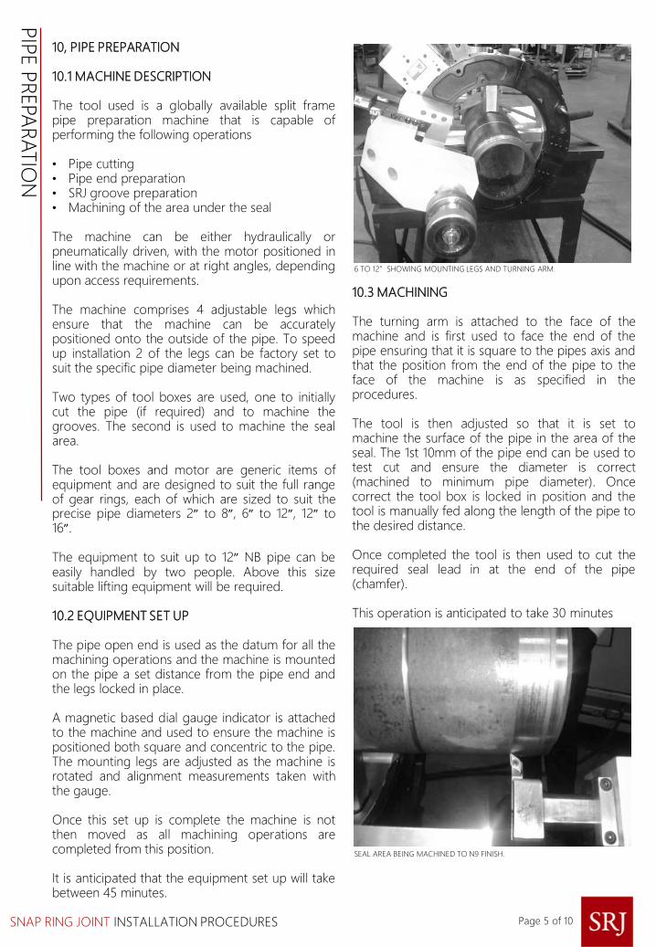
10, PIPE PREPARATION
10.1 MACHINE DESCRIPTION
The tool used is a globally available split framepipe preparation machine that is capable ofperforming the following operations
• Pipe cutting• Pipe end preparation• SRJ groove preparation• Machining of the area under the seal
The machine can be either hydraulically orpneumatically driven, with the motor positioned inline with the machine or at right angles, dependingupon access requirements.
The machine comprises 4 adjustable legs whichensure that the machine can be accuratelypositioned onto the outside of the pipe. To speedup installation 2 of the legs can be factory set tosuit the specific pipe diameter being machined.
Two types of tool boxes are used, one to initiallycut the pipe (if required) and to machine thegrooves. The second is used to machine the sealarea.
The tool boxes and motor are generic items ofequipment and are designed to suit the full rangeof gear rings, each of which are sized to suit theprecise pipe diameters 2” to 8”, 6” to 12”, 12” to16”.
The equipment to suit up to 12” NB pipe can beeasily handled by two people. Above this sizesuitable lifting equipment will be required.
10.2 EQUIPMENT SET UP
The pipe open end is used as the datum for all themachining operations and the machine is mountedon the pipe a set distance from the pipe end andthe legs locked in place.
A magnetic based dial gauge indicator is attachedto the machine and used to ensure the machine ispositioned both square and concentric to the pipe.The mounting legs are adjusted as the machine isrotated and alignment measurements taken withthe gauge.
Once this set up is complete the machine is notthen moved as all machining operations arecompleted from this position.
It is anticipated that the equipment set up will takebetween 45 minutes.
10.3 MACHINING
The turning arm is attached to the face of themachine and is first used to face the end of thepipe ensuring that it is square to the pipes axis andthat the position from the end of the pipe to theface of the machine is as specified in theprocedures.
The tool is then adjusted so that it is set tomachine the surface of the pipe in the area of theseal. The 1st 10mm of the pipe end can be used totest cut and ensure the diameter is correct(machined to minimum pipe diameter). Oncecorrect the tool box is locked in position and thetool is manually fed along the length of the pipe tothe desired distance.
Once completed the tool is then used to cut therequired seal lead in at the end of the pipe(chamfer).
This operation is anticipated to take 30 minutes
6 TO 12”SHOWING MOUNTING LEGS AND TURNING ARM.
SEAL AREA BEING MACHINED TO N9 FINISH.
Page 5 of 10
PIP
E P
REPA
RA
TIO
N

SNAP RING JOINT INSTALLATION PROCEDURES
The tool box is then removed and twin boxes areattached 180 degrees apart to the face of themachine. Each box contains a form tool sized tothe required groove. Each tool is held in the boxspaced with pre-set packers, which ensure that theposition of the grooves is exactly to specification.
GROOVE TOOL BOXES SHOWING PACKERS TO ACCURATELY SET SPACING.
Once locked in place the boxes are automaticallyfed into the pipe cutting the grove, the depth iscontrolled by the number of revolutions of eachtool box feed wheel. The grooves are cutsimultaneously. The grove cutting operation iscompleted within 10 minutes.
GROOVES BEING SIMULTANEOUSLY MACHINED..
GROOVES CUTTING NEARING COMPLETION..
Page 6 of 10
PIP
E P
REPA
RA
TIO
N

SNAP RING JOINT INSTALLATION PROCEDURES Page 7 of 10
APPEN
DIX
I : LLOYD
’S R
EG
ISTER
TYPE A
PPRO
VA
L
SNAP RING JOINT INSTALLATION PROCEDURES Page 8 of 10
APPEN
DIX
I: LLOYD
’S R
EG
ISTER
TYPE A
PPRO
VA
L
SNAP RING JOINT INSTALLATION PROCEDURES
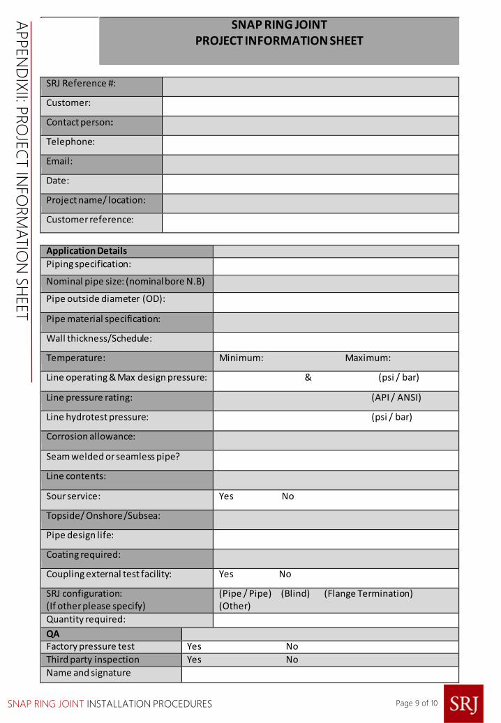
SNAP RING JOINT PROJECT INFORMATION SHEET
SRJ Reference #:
Customer:
Contact person:
Telephone:
Email:
Date:
Project name/ location:
Customer reference:
Application Details
Piping specification:
Nominal pipe size: (nominal bore N.B)
Pipe outside diameter (OD):
Pipe material specification:
Wall thickness/Schedule:
Temperature: Minimum: Maximum:
Line operating & Max design pressure: & (psi / bar)
Line pressure rating: (API / ANSI)
Line hydrotest pressure: (psi / bar)
Corrosion allowance:
Seam welded or seamless pipe?
Line contents:
Sour service: Yes No
Topside/ Onshore /Subsea:
Pipe design life:
Coating required:
Coupling external test facility: Yes No
SRJ configuration: (If other please specify)
(Pipe / Pipe) (Blind) (Flange Termination) (Other)
Quantity required:
QA
Factory pressure test Yes No Third party inspection Yes No Name and signature
Page 9 of 10
APPEN
DIX
II: PRO
JEC
T IN
FO
RM
ATIO
N S
HEET

9 THE ESPLANADE,ST. HELIER,JERSEY, JE2 3QA.
TELEPHONE: +44 1534 626818E-MAIL: [email protected]
SNAP RING JOINT LIMITED.
Every effort has been made to ensure that the information contained in this publication is accurate at the time of publishing. Snap Ring Joint Ltd assumes no responsibility or liability for typographical errors or omissions or for any misinterpretation of theinformation within the publication and reserves the right to change without notice.
Page 10 of 10


![DEPARTMENT OF ENERGY [AU-RM-16-WSHP] RIN 1992 … · ASME B31.8-2016, Gas Transmission and Distribution Piping Systems, ASME Code for Pressure Piping, ... G. Review Under the Unfunded](https://img.dokumen.tips/doc/110x75/5ad675e17f8b9a075a8e3de1/department-of-energy-au-rm-16-wshp-rin-1992-b318-2016-gas-transmission-and.jpg)