Embed Size (px)
DESCRIPTION
b31.8 gas transmission
Citation preview
1999B31.8GAS TRANSMISSION AND DISTRIBUTION PIPING SYSTEMS
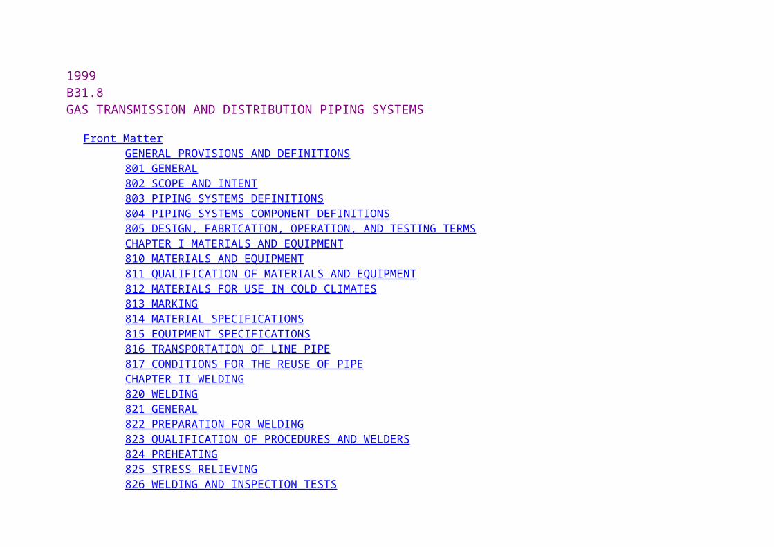
Front Matter GENERAL PROVISIONS AND DEFINITIONS 801 GENERAL 802 SCOPE AND INTENT 803 PIPING SYSTEMS DEFINITIONS 804 PIPING SYSTEMS COMPONENT DEFINITIONS 805 DESIGN, FABRICATION, OPERATION, AND TESTING TERMS CHAPTER I MATERIALS AND EQUIPMENT 810 MATERIALS AND EQUIPMENT 811 QUALIFICATION OF MATERIALS AND EQUIPMENT 812 MATERIALS FOR USE IN COLD CLIMATES 813 MARKING 814 MATERIAL SPECIFICATIONS 815 EQUIPMENT SPECIFICATIONS 816 TRANSPORTATION OF LINE PIPE 817 CONDITIONS FOR THE REUSE OF PIPE CHAPTER II WELDING 820 WELDING 821 GENERAL 822 PREPARATION FOR WELDING 823 QUALIFICATION OF PROCEDURES AND WELDERS 824 PREHEATING 825 STRESS RELIEVING 826 WELDING AND INSPECTION TESTS
827 REPAIR OR REMOVAL OF DEFECTIVE WELDS IN PIPING INTENDED TO OPERATE AT 20% OR MORE OF THE SPECIFIED MINIMUM YIELD STRENGTH
CHAPTER III PIPING SYSTEM COMPONENTS AND FABRICATION DETAILS 830 PIPING SYSTEM COMPONENTS AND FABRICATION DETAILS 831 PIPING SYSTEM COMPONENTS
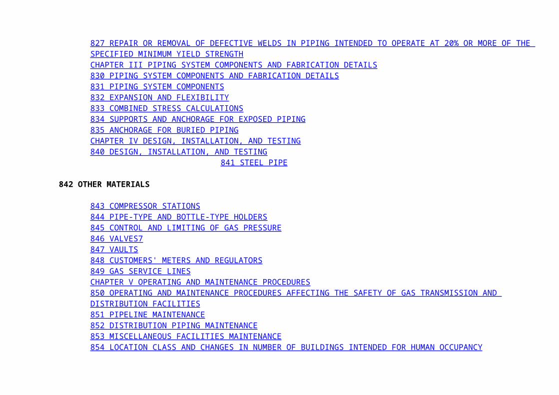
832 EXPANSION AND FLEXIBILITY 833 COMBINED STRESS CALCULATIONS 834 SUPPORTS AND ANCHORAGE FOR EXPOSED PIPING 835 ANCHORAGE FOR BURIED PIPING CHAPTER IV DESIGN, INSTALLATION, AND TESTING 840 DESIGN, INSTALLATION, AND TESTING 841 STEEL PIPE
842 OTHER MATERIALS 843 COMPRESSOR STATIONS 844 PIPE-TYPE AND BOTTLE-TYPE HOLDERS 845 CONTROL AND LIMITING OF GAS PRESSURE 846 VALVES7 847 VAULTS 848 CUSTOMERS' METERS AND REGULATORS 849 GAS SERVICE LINES CHAPTER V OPERATING AND MAINTENANCE PROCEDURES
850 OPERATING AND MAINTENANCE PROCEDURES AFFECTING THE SAFETY OF GAS TRANSMISSION AND DISTRIBUTION FACILITIES
851 PIPELINE MAINTENANCE 852 DISTRIBUTION PIPING MAINTENANCE 853 MISCELLANEOUS FACILITIES MAINTENANCE 854 LOCATION CLASS AND CHANGES IN NUMBER OF BUILDINGS INTENDED FOR HUMAN OCCUPANCY 855 CONCENTRATIONS OF PEOPLE IN LOCATION CLASSES 1 AND 2 856 PIPELINE SERVICE CONVERSIONS CHAPTER VI CORROSION CONTROL 860 CORROSION CONTROL 861 SCOPE 862 EXTERNAL CORROSION CONTROL 863 INTERNAL CORROSION CONTROL 864 PIPELINES IN ARCTIC ENVIRONMENTS 865 PIPELINES IN HIGH TEMPERATURE SERVICE 866 STRESS CORROSION AND OTHER PHENOMENA 867 RECORDS CHAPTER VII MISCELLANEOUS
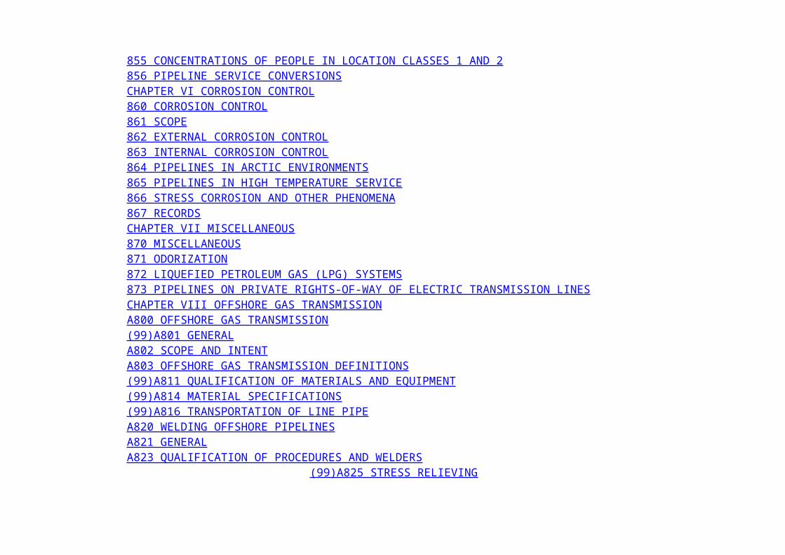
870 MISCELLANEOUS 871 ODORIZATION 872 LIQUEFIED PETROLEUM GAS (LPG) SYSTEMS 873 PIPELINES ON PRIVATE RIGHTS-OF-WAY OF ELECTRIC TRANSMISSION LINES CHAPTER VIII OFFSHORE GAS TRANSMISSION A800 OFFSHORE GAS TRANSMISSION (99)A801 GENERAL A802 SCOPE AND INTENT A803 OFFSHORE GAS TRANSMISSION DEFINITIONS (99)A811 QUALIFICATION OF MATERIALS AND EQUIPMENT (99)A814 MATERIAL SPECIFICATIONS (99)A816 TRANSPORTATION OF LINE PIPE A820 WELDING OFFSHORE PIPELINES A821 GENERAL A823 QUALIFICATION OF PROCEDURES AND WELDERS (99)A825 STRESS RELIEVING
A826 WELDING AND INSPECTION TESTS A830 PIPING SYSTEM COMPONENTS AND FABRICATION DETAILS (99)A831 PIPING SYSTEM COMPONENTS (99)A832 EXPANSION AND FLEXIBILITY A834 SUPPORTS AND ANCHORAGE FOR EXPOSED PIPING (99)A835 ANCHORAGE FOR BURIED PIPING A840 DESIGN, INSTALLATION, AND TESTING A841 DESIGN CONSIDERATIONS A842 STRENGTH CONSIDERATIONS (99)A843 COMPRESSOR STATIONS (99)A844 ON-BOTTOM STABILITY A845 CONTROL AND LIMITING OF GAS PRESSURE A846 VALVES A847 TESTING
A850 OPERATING AND MAINTENANCE PROCEDURES AFFECTING THE SAFETY OF GAS TRANSMISSION AND DISTRIBUTION FACILITIES
A851 PIPELINE MAINTENANCE (99)A854 LOCATION CLASS
A860 CORROSION CONTROL OF OFFSHORE PIPELINES (99)A861 SCOPE A862 EXTERNAL CORROSION CONTROL (99)A863 INTERNAL CORROSION CONTROL (99) CHAPTER IX SOUR GAS SERVICE B800 SOUR GAS SERVICE B801GENERAL B802 SCOPE AND INTENT B803 SOUR GAS TERMS AND DEFINITIONS B813 MARKING B814 MATERIAL SPECIFICATIONS B820 WELDING SOUR GAS PIPELINES B821GENERAL B822 PREPARATION FOR WELDING B823 QUALIFICATIONS OF PROCEDURES AND WELDERS B824PREHEATING B825 STRESS RELIEVING B826 WELDING AND INSPECTION TESTS
B830 PIPING SYSTEM COMPONENTS AND FABRICATION DETAILS B831 PIPING SYSTEM COMPONENTS B840 DESIGN, INSTALLATION, AND TESTING B841 STEEL PIPE B842 OTHER MATERIALS B843 COMPRESSOR STATIONS B844 PIPE-TYPE AND BOTTLE-TYPE HOLDERS B850 ADDITIONAL OPERATING AND MAINTENANCE CONSIDERATIONS AFFECTING THE SAFETY OF SOUR GAS PIPELINES B851 PIPELINE MAINTENANCE B855 CONCENTRATIONS OF PEOPLE IN LOCATION CLASSES 1 AND 2 B860 CORROSION CONTROL OF SOUR GAS PIPELINES B861GENERAL B862 EXTERNAL CORROSION CONTROL B863 INTERNAL CORROSION CONTROL B866 STRESS CORROSION AND OTHER PHENOMENA (99) APPENDIX A REFERENCES
(99) APPENDIX B NUMBERS AND SUBJECTS OF STANDARDS AND SPECIFICATIONS THAT APPEAR IN APPENDIX A APPENDIX C PUBLICATIONS THAT DO NOT APPEAR IN THE CODE OR APPENDIX A APPENDIX D SPECIFIED MINIMUM YIELD STRENGTH FOR STEEL PIPE COMMONLY USED IN PIPING SYSTEMS12 (99) APPENDIX E FLEXIBILITY AND STRESS INTENSIFICATION FACTORS (99) APPENDIX F EXTRUDED HEADERS AND WELDED BRANCH CONNECTIONS13
(99) APPENDIX G TESTING OF WELDERS LIMITED TO WORK ON LINES OPERATING AT HOOP STRESSES OF LESS THAN 20% OF THE SPECIFIED MINIMUM YIELD STRENGTH14
APPENDIX H FLATTENING TEST FOR PIPE15 APPENDIX I END PREPARATIONS FOR BUTTWELDING APPENDIX J COMMONLY USED CONVERSION FACTORS16 APPENDIX K CRITERIA FOR CATHODIC PROTECTION APPENDIX L DETERMINATION OF REMAINING STRENGTH OF CORRODED PIPE17 (99) APPENDIX M GAS LEAKAGE CONTROL CRITERIA18 (99) APPENDIX N RECOMMENDED PRACTICE FOR HYDROSTATIC TESTING OF PIPELINES IN PLACE APPENDIX O PREPARATION OF TECHNICAL INQUIRIES TO THE ASME CODE FOR PRESSURE PIPING, B31 (99) APPENDIX P NOMENCLATURE FOR FIGURES (99) APPENDIX Q SCOPE DIAGRAMS
ASME B31.8-1999 Edition (Revision of ASME B31.8-1995)
GAS TRANSMISSION AND DISTRIBUTION PIPING SYSTEM
ASME CODE FOR PRESSURE PIPING, B31
AN AMERICAN NATIONAL STANDARD
The American Society of Mechanical Engineers
The American Society of Mechanical Engineers
AN AMERICAN NATIONAL STANDARD
GAS TRANSMISSION AND DISTRIBUTION PIPING SYSTEM
ASME CODE FOR PRESSURE PIPING, B31
ASME B31.8-1999 Edition (Revision of ASME B31.8-1995)
Date of Issuance: June 5, 2000
The 1999 Edition of this Code is being issued with an automatic update service that includes Addenda, Interpretations, and Cases. The next Edition is scheduled for publication in 2002.The use of an Addenda allows revisions made in response to public review comments or committee actions to be published on a regular basis; revisions published in Addenda will become effective 6 months after the Date of Issuance of the Addenda.ASME issues written replies to inquiries concerning interpretations of technical aspects of the Code.Periodically certain actions of the ASME B31 Committee will be published as Cases. While these Cases do not constitute formal revisions of the Code, they may be used in specifications, or otherwise, as representing considered opinions of the Committee. The Cases are not part of the Code or the Addenda and are published in a separate supplement.
ASME is the registered trademark of the American Society of Mechanical Engineers.
This code was developed under procedures accredited as meeting the criteria for American National Standards. The Standards Committee that approved the code or standard was balanced to assure that individuals from competent and concerned interests have had an opportunity to participate. The
proposed code or standard was made available for public review and comment that provides an opportunity for additional public input from industry, academia, regulatory agencies, and the public-at-large.ASME does not "approve," "rate," or "endorse" any item, construction, proprietary device, or activity.ASME does not take any position with respect to the validity of any patent rights asserted in connection with any items mentioned in this document, and does not undertake to insure anyone utilizing a standard against liability for infringement of any applicable letters patent, nor assume any such liability. Users of a code or standard are expressly advised that determination of the validity of any such patent rights, and the risk of infringement of such rights, is entirely their own responsibility.Participation by federal agency representative(s) or person(s) affiliated with industry is not to be interpreted as government or industry endorsement of this code or standard.ASME accepts responsibility for only those interpretations issued in accordance with the established ASME procedures and policies, which precludes the issuance of interpretations by individuals.
No part of this document may be reproduced in any form, in an electronic retrieval system or otherwise, without the prior written permission of the publisher.
Copyright © 2000 by THE AMERICAN SOCIETY OF MECHANICAL ENGINEERS Three Park Avenue, New York, New York, 10016-5990 All Rights Reserved Printed in U.S.A.
FOREWORD
The need for a national code for pressure piping became increasingly evident from 1915 to 1925. To meet this need, the American Engineering Standards Committee (later changed to the American Standards Association, now the American National Standards Institute) initiated Project B31 in March 1926 at the request of the American Society of Mechanical Engineers and with that Society as sole sponsor. After several years of work by Sectional Committee B31 and its subcommittees, a first Edition was published in 1935 as an American Tentative Standard Code for Pressure Piping.A revision of the original tentative standard began in 1937. Several more years of effort were given to securing uniformity among sections, eliminating divergent requirements and discrepancies, keeping the Code abreast of current developments in welding technique, calculating stress computations, and including reference to new dimensional and material standards. During this period, a new section added on refrigeration piping was prepared in cooperation with the American Society of Refrigeration Engineers and complemented the American Standard Code for Mechanical Refrigeration. This work culminated in the 1942 American Standard Code for Pressure Piping.Supplements 1 and 2 of the 1942 Code, which appeared in 1944 and 1947, respectively, introduced new dimensional and material standards, a new formula for pipe wall thickness, and more comprehensive requirements for instrument and control piping. Shortly after the 1942 Code was issued, procedures were established for handling inquires requiring explanation or interpretation of Code requirements and for publishing such inquiries and answers in Mechanical Engineering for the information of all concerned.By 1948, continuing increases in the severity of service conditions combined with the development

of new materials and designs to meet these higher requirements warranted more extensive changes in the Code than could be provided from supplements alone. The decision was reached by the American Standards Association and the sponsor to reorganize the sectional committee and its several subcommittees and to invite the various interested bodies to reaffirm their representatives or to designate new ones.Because of the wide field involved, between 30 and 40 different engineering societies, government bureaus, trade associations, institutes, and similar organizations have had one or more representatives on the sectional committee, plus a few "members at large" to represent general interests. Code activities have been subdivided according to the scope of the several sections. General direction of Code activities rested with the Standards Committee officers and an executive committee, membership of which consisted principally of Standards Committee officers and section chairmen.Following its reorganization in 1948, Standards Committee B31 made an intensive review of the 1942 Code that resulted in(a) a general revision and extension of requirements to agree with present day practice(b) the revision of references to existing dimensional standards and material specifications and the addition of references to the new ones(c) the clarification of ambiguous or conflicting requirementsA revision was presented for letter ballot vote of Standards Committee B31. Following approval by this body, the project was approved by the sponsor organization and by the American Standards Association. It was finally designated as an American Standard in February 1951, with the designation B31.1-1951.Standards Committee B31 at its annual meeting of November 29, 1951, authorized the separate publication of a section of the Code for Pressure Piping addressing gas transmission and distribution piping systems, to be complete with the applicable parts of Section 2, Gas and Air Piping Systems, Section 6, Fabrication Details, and Section 7, Materials - Their Specifications and Identification. The purpose was to provide an integrated document for gas transmission and distribution piping that would not require cross-referencing to other sections of the Code.The first Edition of this integrated document, known as American Standard Code for Pressure Piping, Section 8, Gas Transmission and Distribution Piping Systems, was published in 1952 and consisted almost entirely of material taken from Sections 2, 6, and 7 of the 1951 Edition of the Pressure Piping Code.A new section committee was organized in 1952 to update Section 8 as necessary to address modern materials and methods of construction and operation.After a review by B31 Executive and Standards Committees in 1955, a decision was made to develop and publish industry sections as separate Code documents of the American Standard B31 Code for Pressure Piping. The 1955 Edition constituted a general revision of the 1952 Edition with a considerably expanded scope. Further experience in the application of the Code resulted in revisions in 1958, 1963, 1966, 1967, 1968, 1969, 1975, and 1982.In December 1978, the American National Standards Committee B31 was reorganized as the ASME Code for Pressure Piping, B31 Committee. The code designation was also changed to ANSI/ASME B31.The 1989 Edition of the Code was a compilation of the 1986 Edition and the subsequent addenda issued to the 1986 Edition.The 1992 Edition of the Code was a compilation of the 1989 Edition, the subsequent three addenda, and the two special Errata issued to the 1989 Edition.The 1995 Edition of the Code is a compilation of the 1992 Edition and the subsequent three addenda issued to the 1992 Edition.

The 1999 Edition of the Code is a compilation of the 1995 Edition and the revisions that have occurred since the issuance of the 1995 Edition. This Edition was approved by the American National Standards Institute on June 24, 1999.
ASME CODE FOR PRESSURE PIPING, B31
OFFICERS
L. E. Hayden, Jr., Chair B. P. Holbrook, Vice Chair J. Yarmush, Secretary
COMMITTEE PERSONNEL
H. A. Ainsworth, Sudbury, Massachusetts R. J. T. Appleby, Exxon Mobil Upstream Research Co., Houston, Texas K. C. Bodenhamer, Williams Energy Service, Tulsa, Oklahoma P. A. Bourquin, Pleasantville, New York J. D. Byers, Mobil E&P Technology, Dallas, Texas J. S. Chin, ANR Pipeline, Detroit, Michigan P. D. Flenner, Consumers Energy Co., Covert, Michigan D. M. Fox, TXU-Pipeline Services, Dallas, Texas J. W. Frey, Reliant Energy Co., Houston, Texas D. R. Frikken, Solutia, Inc., Gerald, Missouri P. H. Gardner, Wilmington, Delaware R. W. Haupt, Pressure Piping Engineering Associates, Inc., Foster City, California L. E. Hayden, Jr., Victaulic Company of America, Easton, Pennsylvania R. R. Hoffmann, Federal Energy Regulatory Commission, Washington, District of Columbia B. P. Holbrook, Babcock Borsig Power-D B. Riley, Worcester, Massachusetts G. A. Jolly, Edward Vogt Valve Co., Jeffersonville, Indiana W. J. Koves, UOP LLC, Des Plaines, Illinois K. K. Kyser, York Refrigeration-Frick, Waynesboro, Pennsylvania W. B. McGehee, Houston, Texas J. E. Meyer, Middough Association, Inc., Cleveland, Ohio E. Michalopoulos, Hartford Steam Boiler Inspection and Insurance Co., Hartford, Connecticut A. D. Nance, A. D. Nance Associates, Inc., Evans, Georgia W. V. Richards, William V. Richards, Inc., Lincolnshire, Illinois E. H. Rinaca, Virginia Power Company, Glen Allen, Virginia M. J. Rosenfeld, Kiefner and Associates, Worthington, Ohio R. J. Silvia, Process Engineers and Constructors, Inc., Warwick, Rhode Island W. J. Sperko, Sperko Engineering Service, Inc., Greensboro, North Carolina G. W. Spohn III, Coleman Spohn Corp., Cleveland, Ohio R. W. Straiton, Spring, Texas A. L. Watkins, Perry Nuclear Plant, Perry, Ohio R. B. West, State of Iowa, Des Moines, Iowa

B31.8 GAS TRANSMISSION AND DISTRIBUTION PIPING SYSTEMS SECTION COMMITTEE
W. B. McGehee, Chair, Houston, Texas F. S. Fitzgerald, Secretary, ASME, New York, New York D. D. Anderson, Columbia Gas Transmission Corp., Washington. Pennsylvania
R. J. T. Appleby, Exxon Mobil Upstream Research Co., Houston, Texas G. Aragon, El Paso Natural Gas, El Paso, Texas J. Barna, Columbia Gas Transmission, Charleston, West Virginia R. C. Becken, Pacific Gas and Electric Co., Walnut Creek, California L. M. Burns, Colorado/Interstate Gas Co., Colorado Springs, Colorado J. S. Chin, ANR Pipeline Co., Detroit, Michigan S. C. Coffman, KN Energy, Lakewood, Colorado R. L. Dean, ConReg Associates, Houston, Texas A. J. Del Buono, League City, Texas J. C. DeVore, Gas Engineering and Operations, Green Valley, Arizona J. A. Drake, Duke Energy, Houston, Texas J. J. Fallon, Jr., Public Service Electric and Gas Co., Newark, New Jersey R. Favila, El Paso Natural Gas Company, El Paso, Texas J. W. Fee, Kellogg-Brown and Root, Inc., Houston, Texas F. R. Fleet, Consultant, Westmont, Illinois M. A. Francis, LTV Steel Tubular Products Co., Youngstown, Ohio E. N. Freeman, T. D. Williamson, Inc., Tulsa, Oklahoma L. M. Furrow, U. S. Department of Transportation, Washington, District of Columbia J. E. Hansford, Consultant, Houston, Texas J. B. Harris, Jr., Phillips Driscopipe, Richardson, Texas M. E. Hovis, CMS Panhandle Pipeline Co., Houston, Texas M. D. Huston, Oklahoma Natural Gas Co., Tulsa, Oklahoma D. L. Johnson, Enron Pipeline Group, Houston, Texas E. A. Jonas, Consultant, Bethlehem, Pennsylvania K. B. Kaplan, Brown and Root Energy Service, Houston, Texas J. M. Kelly, Willbros Engineers, Inc., Tulsa, Oklahoma S. J. LeBlanc, Exxon Mobil Development Co., Dallas, Texas R. D. Lewis, H. Rosen USA, Inc., Houston, Texas A. I. Macdonald, Consultant, Upland, California A. J. Maghes, Duke Energy, Massillon, Ohio W. J. McGowan, Southern Cross/West Corp., Hayward, California M. J. Mechlowicz, Southern California Gas, Los Angeles, California C. J. Miller, Gulf Interstate Engineering, Houston, Texas D. K. Moore, Tennessee Gas Pipeline, Houston, Texas R. A. Mueller, Dynegy Midstream Services, Houston, Texas R. S. Neuman, Williams Gas Pipelines-Transco, Houston, Texas A. C. Newsome, Jr., Tennessee Gas Pipeline, Houston, Texas A. T. Richardson, Richardson Engineering Co., Marble Falls, Texas C. G. Roberts, Fluor Daniel, Sugar Land, Texas M. J. Rosenfeld, Kiefner and Associates, Inc., Worthington, Ohio L. A. Salinas, Tennessee Gas Pipeline Co., Houston, Texas
R. A. Schmidt, Trinity-Ladish Co., Russellville, Arkansas B. Taksa, Gulf Interstate Engineering, Houston, Texas C. J. Tateosian, Gas System Engineering, Inc., Walnut Creek, California A. T. Tyler, Consultant, Durango, Colorado P. L. Vaughan, ENRON, Houston, Texas F. R. Volgstadt, Perfection Corp., Madison, Ohio E. L. Von Rosenberg, Materials and Welding Technology, Inc., Houston, Texas
D. Wilson, Consultant, Plano, Texas R. A. Wolf, Willbros Engineers, Tulsa, Oklahoma K. F. Wrenn, Jr., Consultant, Charleston, West Virginia C. C. Wright, Jr., Paola, Kansas D. W. Wright, Sun Pipe Line Co., Tulsa, Oklahoma D. B. Yardley, Phillips Petroleum Co., Bartlesville, Oklahoma J. S. Zurcher, Columbia Gas Transportation Co., Charleston, West Virginia
B31.8 EXECUTIVE COMMITTEE
W. B. McGehee, Chair, Houston, Texas F. S. Fitzgerald, Secretary, ASME, New York, New York J. S. Chin, ANR Pipeline Co., Detroit, Michigan J. C. DeVore, Gas Engineering and Operations, Green Valley, Arizona F. R. Fleet, Consultant, Westmont, Illinois K. B. Kaplan, Brown and Root, Inc., Houston, Texas J. M. Kelly, Willbros Engineers, Inc., Tulsa, Oklahoma A. J. Maghes, Duke Energy, Houston, Texas D. K. Moore, Tennessee Gas Pipeline, Houston, Texas A. T. Richardson, Richardson Engineering Co., Houston, Texas A. T. Tyler, Consultant, Durango, Colorado D. Wilson, Consultant, Plano, Texas
B31 ADMINISTRATIVE COMMITTEE
L. E. Hayden, Jr., Chair, Victaulic Company of America, Easton, Pennsylvania B. P. Holbrook, Vice Chair, Babcock Borsig Power - D. B. Riley, Worcester, Massachusetts J. Yarmush, Secretary, ASME, New York, New York K. C. Bodenhamer, Williams Energy Service, Tulsa, Oklahoma J. D. Byers, Mobil E&P Technology, Dallas, Texas P. D. Flenner, Consumers Energy Co., Covert, Michigan A. D. Nance, A. D. Nance Associates, Inc., Evans, Georgia
B31 MATERIALS, FABRICATION, AND EXAMINATION TECHNICAL COMMITTEE
P. D. Flenner, Chair, Consumers Power Co., Covert, Michigan J. Yarmush, Secretary, ASME, New York, New York J. P. Ellenberger, WFI International, Inc., Houston, Texas D. J. Fetzner, ARCO-Alaska, Inc., Anchorage, Alaska
E. Michalopoulos, Hartford Steam Boiler Inspection and Insurance Co., Hartford, Connecticut W. G. Scruggs, DuPont, Wilmington, Delaware R. I. Seals, Berkeley, California R. J. Silvia, Process Engineering and Constructors, Inc., Warwick, Rhode Island
W. J. Sperko, Sperko Engineering Services, Inc., Greensboro, North Carolina E. F. Summers, Jr., Babcox and Wilcox, Barberton, Ohio
B31 MECHANICAL DESIGN TECHNICAL COMMITTEE
R. W. Haupt, Chair, Pressure Piping Engineering Associates, Inc., Foster City, California J. Yarmush, Secretary, ASME, New York, New York G. A. Antaki, Westinghouse Savannah River Co., Aiken, South Carolina C. Becht IV, Becht Engineering Co., Liberty Corner, New Jersey J. P. Breen, Pressure Sciences, Inc., Pittsburgh, Pennsylvania J. P. Ellenberger, WFI International, Inc., Houston, Texas D. J. Fetzner, ARCO-Alaska, Inc., Anchorage, Alaska J. A. Graziano, Tennessee Valley Authority, Chattanooga, Tennessee J. D. Hart, SSD Engineering Consultants, Walnut Creek, California B. P. Holbrook, Babcock Borsig Power - D. B. Riley, Worcester, Massachusetts W. J. Koves, UOP, Inc., Des Plaines, Illinois G. Mayers, Naval Sea Systems Command, Arlington, Virginia T. Q. McCawley, Charlotte, North Carolina E. Michalopoulos, Hartford Steam Boiler Inspection and Insurance Co., Hartford, Connecticut J. C. Minichiello, JC Minichiello Consulting, Inc., Lake Bluff, Illinois A. D. Nance, A. D. Nance Associates, Inc., Evans, Georgia T. J. O'Grady II, ARCO-Alaska, Inc., Anchorage, Alaska A. W. Paulin, Paulin Research Group, The Woodlands, Texas P. S. Rampone, Hart Design Group, Greenville, Rhode Island R. A. Robleto, Kellogg, Brown, and Root, Inc., Houston, Texas E. C. Rodabaugh, Dublin, Ohio M. J. Rosenfeld, Kiefner and Associates, Inc., Worthington, Ohio G. Stevick, Berkeley Engineering and Research, Inc., Berkeley, California Q. N. Truong, Kellogg, Brown, and Root, Inc., Houston, Texas E. A. Wais, Wais and Associates, Inc., Norcross, Georgia G. E. Woods, Houston, Texas
B31 CONFERENCE GROUP
T. A. Bell, Pipeline Safety Engineer, Utilities Engineer, Olympia, Washington G. Bynog, Texas Department of Labor and Standards, Austin, Texas M. Crawford, Weston Resources, Topeka, Kansas R. Coomes, Department of Housing/Boiler Section, Frankfort, Kentucky J. W. Greenawalt, Jr., Oklahoma Department of Labor, Oklahoma City, Oklahoma H. D. Hanrath, North Carolina Department of Labor/Boiler Safety Bureau,
Raleigh, North Carolina C. J. Harvey, Alabama Public Service Commission, Montgomery, Alabama D. T. Jagger, Ohio Department of Commerce, Reynoldsburg, Ohio M. Kotb, Regie du Batiment du Quebec, Montreal, Quebec, Canada K. T. Lau, Alberta Boiler and Pressure Vessel Safety, Edmonton, Alberta, Canada R. G. Marini, New Hampshire Public Utilities Commission, Concord, New Hampshire I. W. Mault, Manitoba Department of Labour, Winnipeg, Manitoba, Canada A. W. Meiring, Department of Fire Prevention and Building Safety, Indianapolis, Indiana R. F. Mullaney, Boiler and Pressure Vessel Safety Branch, Vancouver, British Columbia, Canada W. A. Owen, North Dakota Public Service Commission, Bismarck, North Dakota W. M. Picardo, Department of Consumer and Regulatory Affairs, Washington, District of Columbia P. Sher, Department of Public Utility Control, New Britain, Connecticut H. E. Shutt, Illinois Commerce Commission, Springfield, Illinois M. E. Skarda, Department of Labor, Little Rock, Arkansas D. A. Starr, Department of Labor, Lincoln, Nebraska D. Stursma, Iowa Utilities Board, Des Moines, Iowa R. P. Sullivan, National Board of Boiler and Pressure Vessel Inspectors, Columbus, Ohio J. E. Troppman, Division of Labor/Boiler Inspection, Denver, Colorado R. W. Vindich, Department of Labor and Industry, Harrisburg, Pennsylvania C. H. Walters, National Board, Columbus, Ohio W. A. West, ACI Central, Charlottetown, Prince Edward Island, Canada T. F. Wickham, Department of Labor, Providence, Rhode Island
B31 NATIONAL INTEREST REVIEW GROUP
H. G. Anderson, Parker-Hannifin Corp., Columbus, Ohio W. C. Carnell, American Institute of Chemical Engineers A. Cohen, Arthur Cohen & Associates, Albuquerque, New Mexico R. Fletcher, Peabody Engineering Corp., Shelton, Connecticut D. R. Frikken, Solutia, Inc., Gerald, Montana R. A. Handschumacher, Handschumacher Associated, Saunderstown, Rhode Island J. Hausmann, National Certified Pipe Welding, Rockville, Maryland J. M. Holleran, Consultant, Westlake, Ohio L. Katz, Consultant, Bronx, New York H. R. Kornblum, Consultant, Great Neck, New York T. C. Lemoff, National Fire Protection Association, Quincy, Massachusetts M. F. Melchioris, Praxair Inc., Tonawanda, New York R. A. Schmidt, Trinity-Ladish, Frederick, Maryland D. W. Snyder, MS Public Service Commission, Jackson, Mississippi T. F. Stroud, Ductile Iron Pipe Research Association, Birmingham, Alabama H. Thielsch, Thielsch Engineering Inc., Cranston, Rhode Island
G. M. von Bargen, International District Heating & Cooling, Franklin, Wisconsin R. E. White, Richard E. White & Associates PC, South Bend, Indiana R. L. Williams, Duke Power Co., Charlotte, North Carolina
(99)INTRODUCTION
The ASME Code for Pressure Piping consists of many individually published sections, each an American National Standard. Hereafter, in this Introduction and in the text of this Code Section, B31.8, when the word "Code" is used without specific identification, it means this Code Section.The Code sets forth engineering requirements deemed necessary for the safe design and construction of pressure piping. Although safety is the basic consideration, this factor alone will not necessarily govern the final specifications of any piping system. The designer is cautioned that the Code is not a design handbook; it does not eliminate the need for the designer or for competent engineering judgment.To the greatest possible extent, Code requirements for design are stated in terms of basic design principles and formulas. These are supplemented as necessary with specific requirements to ensure uniform application of principles and to guide selection and application of piping elements. The Code prohibits designs and practices known to be unsafe and contains warnings where caution, but not prohibition, is warranted.This Code Section includes(a) references to acceptable material specifications and component standards, including dimensional and mechanical property requirements(b) requirements for designing components and assemblies(c) requirements and data for evaluating and limiting stresses, reactions, and movements associated with pressure, temperature changes, and other forces(d) guidance and limitations on selecting and applying materials, components, and joining methods(e) requirements for fabricating, assembling, and installing piping(f) requirements for examining, inspecting, and testing piping(g) procedures for operation and maintenance that are essential to public safety(h) provisions for protecting pipelines from external and internal corrosionIt is intended that this Edition of Code Section B31.8 and any subsequent addenda not be retroactive. The latest edition and addenda issued at least 6 months before the original contract date for the first phase of activity covering a piping system or systems shall be the governing document, unless agreement is specifically made between contracting parties to use another issue, or unless the regulatory body having jurisdiction imposes the use of another issue or different requirements.Users of this Code are cautioned against making use of revisions without assurance that they are acceptable to any authorities of jurisdiction where the piping is to be installed.The Code is under the direction of ASME Committee B31, Code for Pressure Piping, which is organized and operates under procedures of The American Society of Mechanical Engineers that have been accredited by the American National Standards Institute. The Committee is a continuing one and keeps all Code Sections current with new developments in materials, construction, and industrial practice. Addenda are issued periodically. New editions are published at intervals of 3 years to 5 years.When no Section of the ASME Code for Pressure Piping specifically covers a piping system, the user has discretion to select any Section determined to be generally applicable; however, it is cautioned that supplementary requirements to the Section chosen may be necessary to provide for a safe piping system for the intended application. Technical limitations of the various Sections, legal
requirements, and possible applicability of other Codes or Standards are some of the factors to be considered by the user in determining the applicability of any Section of this Code.
Interpretations and Revisions
The Committee has established an orderly procedure to consider requests for interpretation and revision of Code requirements. To receive consideration, inquiries must be in writing and must give full particulars. (See Appendix O covering preparation of technical inquiries.)The approved reply to an inquiry will be sent directly to the inquirer. In addition, the question and reply will be published as part of an Interpretation Supplement to the Code Section, issued with Addenda.Requests for interpretation and suggestions for revision should be addressed to the Secretary, ASME B31 Committee, care of The American Society of Mechanical Engineers, Three Park Avenue, New York, New York 10016.
Cases
A Case is the prescribed form of reply to an inquiry when study indicates that the Code wording needs clarification or when the reply modifies existing requirements of the Code or grants permission to use new materials or alternative constructions. Proposed Cases are published in Mechanical Engineering for public review. In addition, the Case will be published as part of an Interpretation Supplement issued with Addenda to the applicable Code Section.A Case is normally issued for a limited period, after which it may be renewed, incorporated in the Code, or allowed to expire if there is no indication of further need for the requirements covered by the Case. The provisions of a Case, however, may be used after its expiration or withdrawal, provided the Case was effective on the original contract date or was adopted before completion of the work, and the contracting parties agree to its use.Materials are listed in the Stress Tables only when sufficient usage in piping within the scope of the Code has been shown. Materials may be covered by a case. Requests for listing shall include evidence of satisfactory usage and specific data to permit establishment of allowable stresses or pressure rating, maximum and minimum temperature limits, and other restrictions. Additional criteria can be found in the guidelines for addition of new materials in the ASME Boiler and Pressure Vessel Code, Section IIand Section VIII, Division 1, Appendix B. (To develop usage and gain experience, unlisted materials may be used in accordance with para. 811.22.)
Effective Date
This Edition, when issued, contains new Code provisions. It is a compilation of the 1995 Edition and revisions to the 1995 Edition.
SUMMARY OF CHANGES
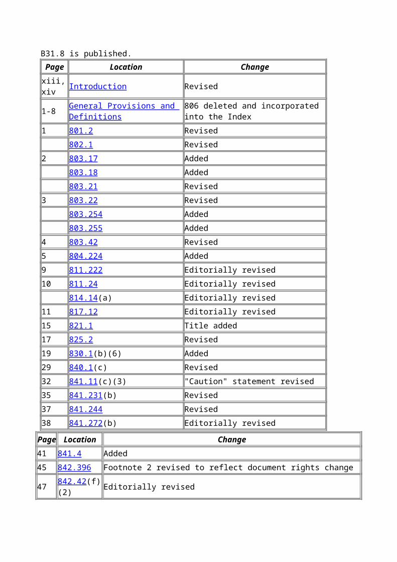
Revisions, additions, deletions, and errata to the ASME B31.8-1995 Edition are included in this edition. A margin designator, (99), is used to identify the affected material and corresponds to the items listed in the Summary of Changes pages. The margin designators will remain on the pages until the 2002 Edition of B31.8 is published.
Page Location Changexiii, xiv Introduction Revised

1-8 General Provisions and Definitions 806 deleted and incorporated into the Index1 801.2 Revised 802.1 Revised2 803.17 Added 803.18 Added 803.21 Revised3 803.22 Revised 803.254 Added 803.255 Added4 803.42 Revised5 804.224 Added9 811.222 Editorially revised10 811.24 Editorially revised 814.14(a) Editorially revised11 817.12 Editorially revised15 821.1 Title added17 825.2 Revised19 830.1(b)(6) Added29 840.1(c) Revised32 841.11(c)(3) "Caution" statement revised35 841.231(b) Revised37 841.244 Revised38 841.272(b) Editorially revised
Page Location Change41 841.4 Added45 842.396 Footnote 2 revised to reflect document rights change47 842.42(f)(2) Editorially revised 842.432(f)(3) Editorially revised50 843.43 Editorially revised51 843.48 Added52 844.32 Editorially revised58 845.411 Editorially revised 845.421 Editorially revised59 845.61(c)(3) Revised71 851.1 Revised 851.4 Revised74 851.9 Editorially revised

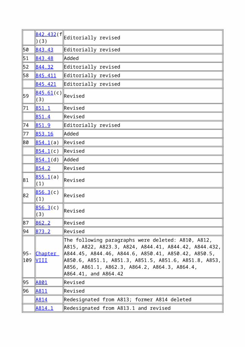
77 853.16 Added80 854.1(a) Revised 854.1(c) Revised 854.1(d) Added 854.2 Revised81 855.1(a)(1) Revised82 856.3(c)(1) Revised 856.3(c)(3) Revised87 862.2 Revised94 873.2 Revised
95-109 Chapter VIII
The following paragraphs were deleted: A810, A812, A815, A822, A823.3, A824, A844.41, A844.42, A844.432, A844.45, A844.46, A844.6, A850.41, A850.42, A850.5, A850.6, A851.1, A851.3, A851.5, A851.6, A851.8, A853, A856, A861.1, A862.3, A864.2, A864.3, A864.4, A864.41, and A864.42
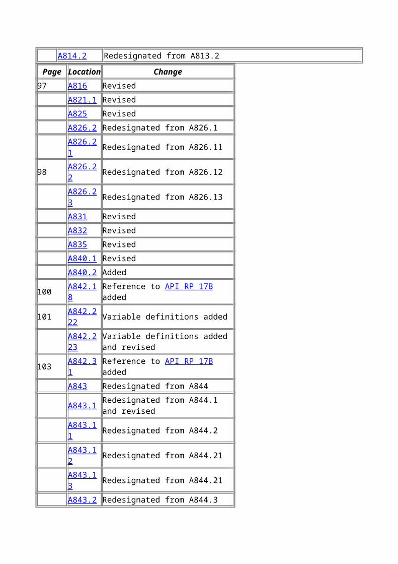
95 A801 Revised96 A811 Revised A814 Redesignated from A813; former A814 deleted A814.1 Redesignated from A813.1 and revised A814.2 Redesignated from A813.2
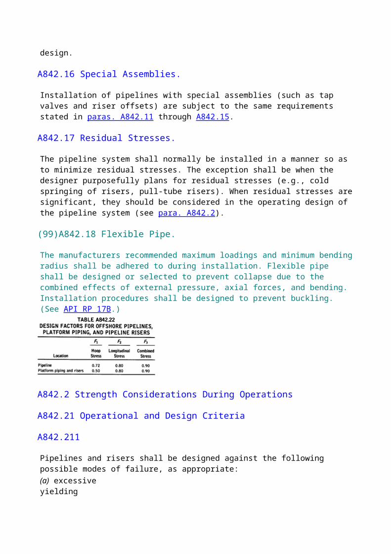
Page Location Change97 A816 Revised A821.1 Revised A825 Revised A826.2 Redesignated from A826.1 A826.21 Redesignated from A826.1198 A826.22 Redesignated from A826.12 A826.23 Redesignated from A826.13 A831 Revised A832 Revised A835 Revised A840.1 Revised A840.2 Added100 A842.18 Reference to API RP 17B added101 A842.222 Variable definitions added A842.223 Variable definitions added and revised103 A842.31 Reference to API RP 17B added A843 Redesignated from A844 A843.1 Redesignated from A844.1 and revised
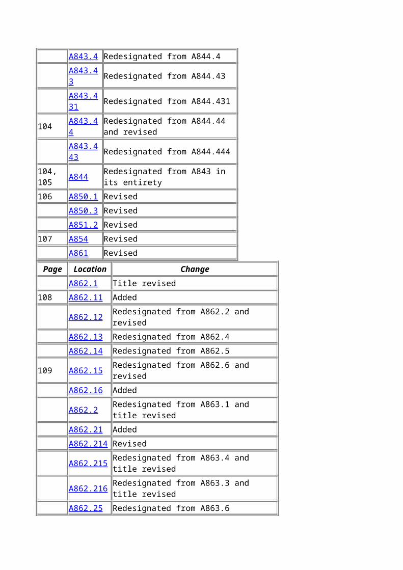
A843.11 Redesignated from A844.2 A843.12 Redesignated from A844.21 A843.13 Redesignated from A844.21 A843.2 Redesignated from A844.3 A843.4 Redesignated from A844.4 A843.43 Redesignated from A844.43 A843.431 Redesignated from A844.431104 A843.44 Redesignated from A844.44 and revised A843.443 Redesignated from A844.444104, 105 A844 Redesignated from A843 in its entirety106 A850.1 Revised A850.3 Revised A851.2 Revised107 A854 Revised A861 Revised
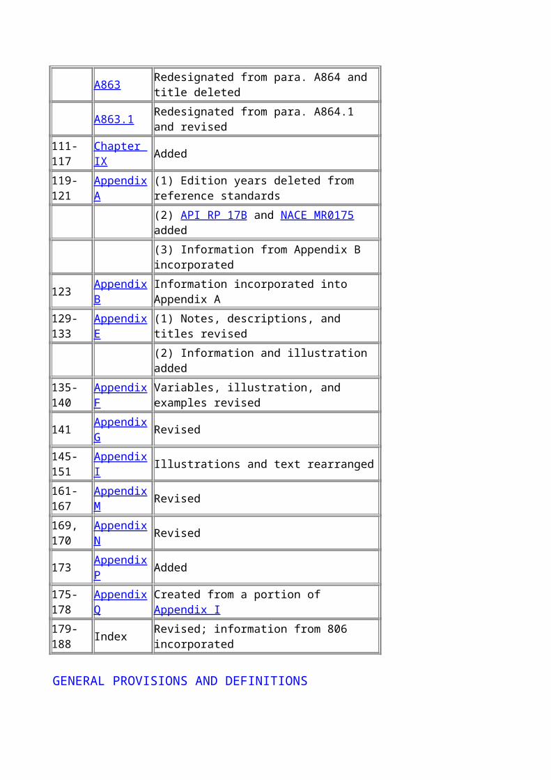
Page Location Change A862.1 Title revised108 A862.11 Added A862.12 Redesignated from A862.2 and revised A862.13 Redesignated from A862.4 A862.14 Redesignated from A862.5109 A862.15 Redesignated from A862.6 and revised A862.16 Added A862.2 Redesignated from A863.1 and title revised A862.21 Added A862.214 Revised A862.215 Redesignated from A863.4 and title revised A862.216 Redesignated from A863.3 and title revised A862.25 Redesignated from A863.6 A863 Redesignated from para. A864 and title deleted A863.1 Redesignated from para. A864.1 and revised111-117 Chapter IX Added119-121 Appendix A (1) Edition years deleted from reference standards (2) API RP 17B and NACE MR0175 added (3) Information from Appendix B incorporated123 Appendix B Information incorporated into Appendix A129-133 Appendix E (1) Notes, descriptions, and titles revised
(2) Information and illustration added135-140 Appendix F Variables, illustration, and examples revised141 Appendix G Revised145-151 Appendix I Illustrations and text rearranged161-167 Appendix M Revised169, 170 Appendix N Revised173 Appendix P Added175-178 Appendix Q Created from a portion of Appendix I179-188 Index Revised; information from 806 incorporated
GENERAL PROVISIONS AND DEFINITIONS
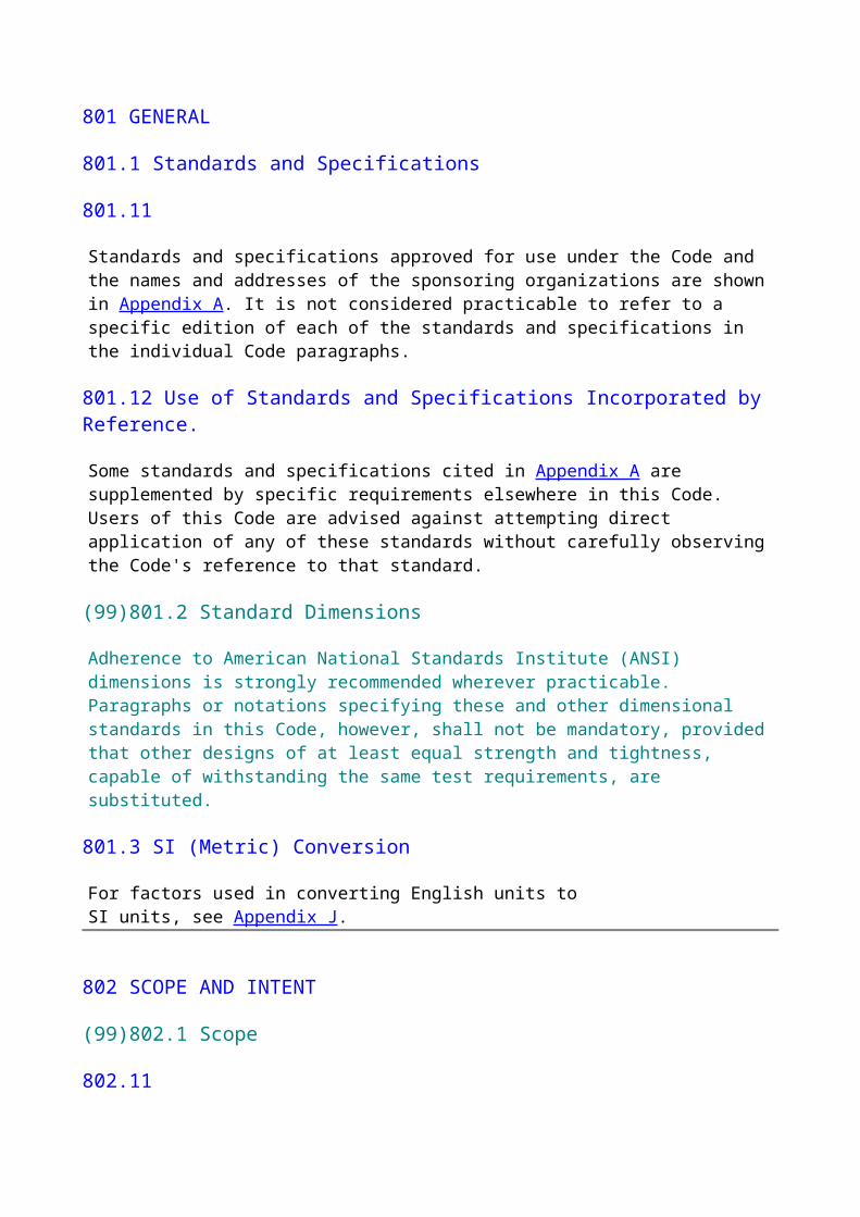
801 GENERAL
801.1 Standards and Specifications
801.11
Standards and specifications approved for use under the Code and the names and addresses of the sponsoring organizations are shown in Appendix A. It is not considered practicable to refer to a specific edition of each of the standards and specifications in the individual Code paragraphs.
801.12 Use of Standards and Specifications Incorporated by Reference.
Some standards and specifications cited in Appendix A are supplemented by specific requirements elsewhere in this Code. Users of this Code are advised against attempting direct application of any of these standards without carefully observing the Code's reference to that standard.
(99)801.2 Standard Dimensions
Adherence to American National Standards Institute (ANSI) dimensions is strongly recommended wherever practicable. Paragraphs or notations specifying these and other dimensional standards in this Code, however, shall not be mandatory, provided that other designs of at least equal strength and tightness, capable of withstanding the same test requirements, are substituted.
801.3 SI (Metric) Conversion
For factors used in converting English units to SI units, see Appendix J.
802 SCOPE AND INTENT
(99)802.1 Scope
802.11
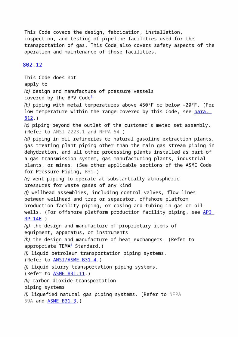
This Code covers the design, fabrication, installation, inspection, and testing of pipeline facilities used for the transportation of gas. This Code also covers safety aspects of the operation and maintenance of those facilities.
802.12
This Code does not apply to(a) design and manufacture of pressure vessels covered by the BPV Code1
(b) piping with metal temperatures above 450°F or below -20°F. (For low temperature within the range covered by this Code, see para. 812.)(c) piping beyond the outlet of the customer's meter set assembly. (Refer to ANSI Z223.1 and NFPA 54.)(d) piping in oil refineries or natural gasoline extraction plants, gas treating plant piping other than the main gas stream piping in dehydration, and all other processing plants installed as part of a gas transmission system, gas manufacturing plants, industrial plants, or mines. (See other applicable sections of the ASME Code for Pressure Piping, B31.)(e) vent piping to operate at substantially atmospheric pressures for waste gases of any kind(f) wellhead assemblies, including control valves, flow lines between wellhead and trap or separator, offshore platform production facility piping, or casing and tubing in gas or oil wells. (For offshore platform production facility piping, see API RP 14E.)(g) the design and manufacture of proprietary items of equipment, apparatus, or instruments(h) the design and manufacture of heat exchangers. (Refer to appropriate TEMA2 Standard.)(i) liquid petroleum transportation piping systems. (Refer to ANSI/ASME B31.4.)(j) liquid slurry transportation piping systems. (Refer to ASME B31.11.)(k) carbon dioxide transportation piping systems(l) liquefied natural gas piping systems. (Refer to NFPA 59A and ASME B31.3.)
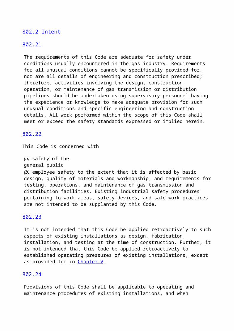
802.2 Intent
802.21
The requirements of this Code are adequate for safety under conditions usually encountered in the gas industry. Requirements for all unusual conditions cannot be specifically provided for, nor are all details of engineering and construction prescribed; therefore, activities involving the design, construction, operation, or maintenance of gas transmission or distribution pipelines should be undertaken using supervisory personnel having the experience or knowledge to make adequate provision for such unusual conditions and specific engineering and construction details. All work performed within the scope of this Code shall meet or exceed the safety standards expressed or implied herein.
802.22
This Code is concerned with
(a) safety of the general public
(b) employee safety to the extent that it is affected by basic design, quality of materials and workmanship, and requirements for testing, operations, and maintenance of gas transmission and distribution facilities. Existing industrial safety procedures pertaining to work areas, safety devices, and safe work practices are not intended to be supplanted by this Code.
802.23
It is not intended that this Code be applied retroactively to such aspects of existing installations as design, fabrication, installation, and testing at the time of construction. Further, it is not intended that this Code be applied retroactively to established operating pressures of existing installations, except as provided for in Chapter V.
802.24
Provisions of this Code shall be applicable to operating and maintenance procedures of existing installations, and when existing installations are uprated.
802.25 Qualification of Those Performing Inspections.
Individuals who perform inspections shall be qualified by training and/or experience to implement the applicable requirements and recommendations of this Code.
803 PIPING SYSTEMS DEFINITIONS
803.1 General Terms
803.11 Gas,
as used in this Code, is any gas or mixture of gases suitable for domestic or industrial fuel and transmitted or distributed to the user through a piping system. The common types are natural gas, manufactured gas, and liquefied petroleum gas distributed as a vapor, with or without the admixture of air.
803.12 Operating company,
as used herein, is the individual, partnership, corporation, public agency, or other entity that operates the gas transmission or distribution facilities.
803.13 Private rights-of-way,
as used in this Code, are rights-of-way not located on roads, streets, or highways used by the public, or on railroad rights-of-way.
803.14 Parallel encroachment,
as used in this Code, is the portion of the route of a pipeline or main that lies within, runs in a generally parallel direction to, and does not necessarily cross the rights-of-way of a road, street, highway, or railroad.
803.15 Hot taps
are branch piping connections made to operating pipelines, mains, or other facilities while they are in operation. The branch piping is connected to the operating line, and the operating line is tapped while it is under gas pressure.
803.16 Vault
is an underground structure that may be entered and that is designed to contain piping and piping components (such as valves or pressure regulators).
(99)803.17 Transportation of gas is gathering,
transmission, or distribution of gas by pipeline or the storage of gas.
(99)803.18 Pipeline
is all parts of physical facilities through which gas moves in transportation, including pipe, valves, fittings, flanges (including bolting and gaskets), regulators, pressure vessels, pulsation dampeners, relief valves, and other appurtenances attached to pipe, compressor units, metering stations, regulator stations, and fabricated assemblies. Included within this definition are gas transmission and gathering lines, including appurtenances, that are installed offshore for transporting gas from production facilities to onshore locations and gas storage equipment of the closed pipe type, which is fabricated or forged from pipe or fabricated from pipe and fittings.
803.2 Piping Systems
(99)803.21 Transmission system
is one or more segments of pipeline, usually interconnected to form a network, which transports gas from a gathering system, the outlet of a gas processing plant, or a storage field to a high- or low-pressure distribution system, a large-volume customer, or another storage field.
803.211 Transmission line
is a segment of pipeline installed in a transmission system between storage fields.
803.212 Storage field
is a geographic field containing a well or group of interconnected wells that are completed for and dedicated to subsurface storage of large quantities of gas for later recovery, transmission, and end use.
(99)803.22 Distribution System
803.221 Low-pressure distribution system
is a gas distribution piping system in which the gas pressure in the mains and service lines is
substantially the same as that delivered to the customer's appliances. In such a system, a service regulator is not required on the individual service lines.
803.222 High-pressure distribution system
is a gas distribution piping system that operates at a pressure higher than the standard service pressure delivered to the customer. In such a system, a service regulator is required on each service line to control the pressure delivered to the customer.
803.223 Gas main or distribution main
is a segment of pipeline in a distribution system pipe installed to convey gas to individual service lines or other mains.
803.224 Gas service line
is the piping installed between a main, pipeline, or other source of supply and the meter set assembly. (See para. 802.12[c].)
803.23 Gathering system
is one or more segments of pipeline, usually interconnected to form a network, that transports gas from one or more production facilities to the inlet of a gas processing plant. If no gas processing plant exists, the gas is transported to the most downstream of (1) the point of custody transfer of gas suitable for delivery to a distribution system, or (2) the point where accumulation and preparation of gas from separate geographic production fields in reasonable proximity has been completed.
803.231 Gathering line
is a segment of pipeline installed in a gathering system.
803.24 Gas storage line
is a pipeline used for conveying gas between a compressor station and a gas well used for storing gas underground.
803.25 Miscellaneous Systems
803.251 Instrument piping
is all piping, valves, and fittings used to connect instruments to main piping, to other instruments and apparatus, or to measuring equipment.
803.252 Control piping
is all piping, valves, and fittings used to interconnect air, gas, or hydraulically operated control apparatus or instrument transmitters and receivers.
803.253 Sample piping
is all piping, valves, and fittings used to collect samples of gas, steam, water, or oil.
(99)803.254 Production facility
is piping or equipment used in production, extraction, recovery, lifting, stabilization, separation, treating, associated measurement, and field compression, gas lift, gas injection, or fuel gas supply. The piping or equipment must be used in extracting petroleum liquids or natural gas from the ground and preparing it for transportation by pipeline.
(99)803.255 Gas processing plant
is a facility used for extracting commercial products from gas.
803.3 Meters, Regulators, and Pressure Relief Stations
803.31 Meters
803.311 Customer's meter
is a meter that measures gas delivered to a customer for consumption on the customer's premises.
803.312 Meter set assembly
is the piping and fittings installed to connect the inlet side of the meter to the gas service line and the outlet side of the meter to the customer's fuel line.
803.32 Regulators
803.321 Service regulator
is a regulator installed on a gas service line to control the pressure of the gas delivered to the customer.
803.322 Monitoring regulator
is a pressure regulator installed in series with another pressure regulator that, in an emergency, automatically assumes control of the pressure downstream of the station, in case that pressure exceeds a set maximum.
803.323 Pressure regulating station
consists of equipment installed for automatically reducing and regulating the pressure in the downstream pipeline or main to which it is connected. Included are piping and auxiliary devices such as valves, control instruments, control lines, the enclosure, and ventilation equipment.
803.324 Pressure limiting station
consists of equipment that under abnormal conditions will act to reduce, restrict, or shut off the supply of gas flowing into a system to prevent the gas pressure from exceeding a predetermined value. While normal pressure conditions prevail, the pressure limiting station may exercise some degree of control of the flow of the gas or may remain in the wide open position. Included in the station are piping and auxiliary devices, such as valves, control instruments, control lines, the enclosure, and ventilating equipment, installed in accordance with the pertinent requirements of this Code.
803.33 Pressure Relief
803.331 Pressure relief station
consists of equipment installed to vent gas from a system being protected to prevent the gas pressure from exceeding a predetermined limit. The gas may be vented into the atmosphere or into a lower pressure system capable of safely absorbing the gas being discharged. Included in the station are piping and auxiliary devices, such as valves, control instruments, control lines, the enclosure, and ventilating equipment, installed in accordance with the pertinent requirements of this Code.
803.4 Valves
803.41 Stop valve
is a valve installed for stopping the flow of gas in a pipe.
(99)803.42 Service line valve
is a stop valve readily operable and accessible for the purpose of shutting off the gas to the customer's fuel line. The stop valve should be located in the service line ahead of the service regulator or ahead of the meter, if a regulator is not provided. The valve is also known as a service line shutoff, a service line cock, or a meter stop.
803.43 Curb valve
is a stop valve installed below grade in a service line at or near the property line, accessible through a curb box or standpipe, and operable by a removable key or wrench for shutting off the gas supply to a building. This valve is also known as a curb shutoff or a curb cock.
803.44 Check valve
is a valve designed to permit flow in one direction and to close automatically to prevent flow in the reverse direction.
803.5 Gas Storage Equipment
803.51 Pipe-type holder
is any pipe container or group of interconnected pipe containers installed at one location and used only for storing gas.
803.52 Bottle,
as used in this Code, is a gas-tight structure completely fabricated from pipe with integral drawn, forged, or spun end closures and tested in the manufacturer's plant.
803.53 Bottle-type holder
is any bottle or group of interconnected bottles installed in one location and used only for storing gas.
804 PIPING SYSTEMS COMPONENT DEFINITIONS
804.1 General
804.11 Plastic Terms
804.111 Plastic
(noun) is a material that contains as an essential ingredient an organic substance of high to ultrahigh molecular weight, is solid in its finished state, and, at some stage of its manufacture or processing, can be shaped by flow. The two general types of plastic referred to in this Code are thermoplastic and thermosetting.
804.112 Thermoplastic
is a plastic that is capable of being repeatedly softened by increase of temperature and hardened by decrease of temperature.
804.113 Thermosetting plastic
is plastic that is capable of being changed into a substantially infusible or insoluble product when cured under application of heat or chemical means.
804.12 Ductile iron,
sometimes called nodular iron, is a cast ferrous material in which the free graphite present is in a spheroidal form, rather than a flake form. The desirable properties of ductile iron are achieved by chemistry and a ferritizing heat treatment of the castings.
804.13
The unqualified term cast iron shall apply to gray cast iron, which is a cast ferrous material in which a major part of the carbon content occurs as free carbon in the form of flakes interspersed throughout the metal.
804.14 Proprietary items
are items made and marketed by a company having the exclusive or restricted right to manufacture and sell them.
804.15 Pipe container
is a gas-tight structure assembled in a shop or in the field from pipe and end closures.
804.2 Pipe
804.21 Pipe and Piping Terms
804.211 Pipe
is a tubular product made for sale as a production item. Cylinders formed from plate during the fabrication of auxiliary equipment are not pipe as defined herein.
804.212 Cold expanded pipe
is seamless or welded pipe that is formed and then cold expanded while in the pipe mill so that the circumference is permanently increased by at least 0.50%.
804.22 Dimensional Terms
804.221 Length
is a piece of pipe of the length delivered from the mill. Each piece is called a length, regardless of its actual dimension. This is sometimes called "joint," but "length" is preferred.
804.222 Nominal wall thickness, t,
is the wall thickness computed by or used in the design equation in para. 841.11 or A842.221 in Chapter VIII. Under this Code, pipe may be ordered to this computed wall thickness without adding allowance to compensate for the underthickness tolerance permitted in approved specifications.
804.223 NPS (nominal pipe size)
is a dimensionless designator of pipe. It indicates a standard pipe size when followed by the appropriate number (e.g., NPS 1 , NPS 12).
(99)804.224 Diameter or nominal outside diameter
is the as-produced or as-specified outside diameter of the pipe, not to be confused with the dimensionless NPS. For example, NPS 12 pipe has a specified outside diameter of 12.750 in., NPS 8 has a specified outside diameter of 8.625 in., and NPS 24 pipe has a specified outside diameter of
24.000 in.
804.23 Mechanical Properties
804.231 Yield strength,
expressed in pounds per square inch, is the strength at which a material exhibits a specified limiting permanent set or produces a specified total elongation under load. The specified limiting set or elongation is usually expressed as a percentage of gage length. Its values are specified in the various material specifications acceptable under this Code.
804.232 Tensile strength,
expressed in pounds per square inch, is the highest unit tensile stress (referred to the original cross section) a material can sustain before failure.
804.233 Specified minimum yield strength (SMYS),
expressed in pounds per square inch, is the minimum yield strength prescribed by the specification under which pipe is purchased from the manufacturer.
804.234 Specified minimum tensile strength,
expressed in pounds per square inch, is the minimum tensile strength prescribed by the specification under which pipe is purchased from the manufacturer.
804.235 Specified minimum elongation
is the minimum elongation (expressed in percent of the gage length) in the tensile test specimen, prescribed by the specifications under which the material is purchased from the manufacturer.
804.24 Steel Pipe
804.241 Carbon Steel.3
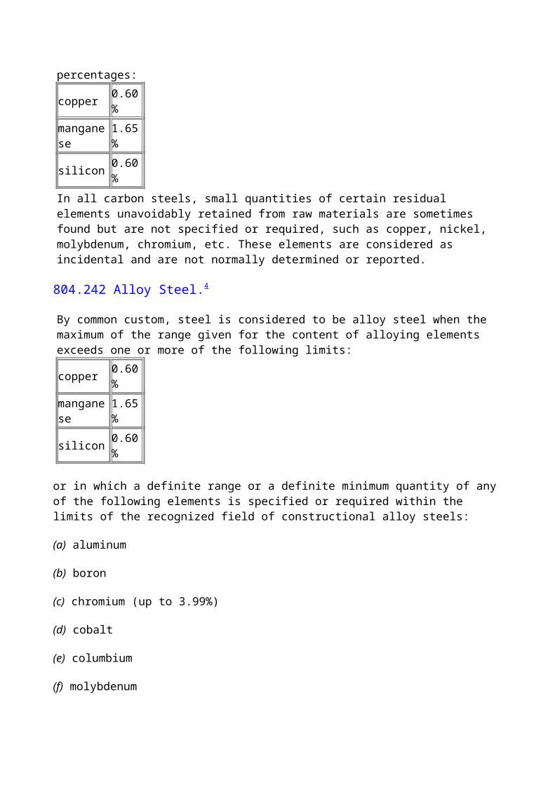
By common custom, steel is considered to be carbon steel when no minimum content is specified or required for aluminum, boron, chromium, cobalt, molybdenum, nickel, niobium, titanium, tungsten, vanadium, zirconium, or any other element added to obtain a desired alloying effect; when the specified minimum for copper does not exceed 0.40%; or when the maximum content specified for any of the following elements does not exceed the following percentages: copper 0.60%manganese 1.65%silicon 0.60%In all carbon steels, small quantities of certain residual elements unavoidably retained from raw materials are sometimes found but are not specified or required, such as copper, nickel, molybdenum, chromium, etc. These elements are considered as incidental and are not normally determined or reported.
804.242 Alloy Steel.4
By common custom, steel is considered to be alloy steel when the maximum of the range given for the content of alloying elements exceeds one or more of the following limits: copper 0.60%manganese 1.65%silicon 0.60%
or in which a definite range or a definite minimum quantity of any of the following elements is specified or required within the limits of the recognized field of constructional alloy steels:
(a) aluminum
(b) boron
(c) chromium (up to 3.99%)
(d) cobalt
(e) columbium
(f) molybdenum
(g) nickel
(h) titanium
(i) tungsten
(j) vanadium
(k) zirconium
or any other alloying element added to obtain a desired alloying effect.Small quantities of certain elements are unavoidably present in alloy steels. In many applications, these are not considered to be important and are not specified or required. When not specified or required, they should not exceed the following amounts: chromium 0.20%copper 0.35%molybdenum 0.06%nickel 0.25%
804.243 Pipe Manufacturing Processes.
Types and names of welded joints are used herein according to their common usage as defined in
ANSI/AWS A3.0, or as specifically defined as follows:(a) Electric-resistance-welded pipe is pipe produced in individual lengths or in continuous lengths from coiled skelp and is subsequently cut into individual lengths. The resulting lengths have a longitudinal butt joint wherein coalescence is produced by the heat obtained from resistance of the pipe to the flow of electric current in a circuit of which the pipe is a part, and by the application of pressure. Typical specifications are ASTM A 53, ASTM A 135, and API 5L.(b) Furnace Butt-Welded Pipe(1) Bell-welded is furnace-welded pipe produced in individual lengths from cut-length skelp. The pipe's longitudinal butt joint forge welded by the mechanical pressure is developed in drawing the furnace-heated skelp through a cone-shaped die (commonly known as a "welding bell"), which serves as a combined forming and welding die. Typical specifications are ASTM A 53 and API 5L.(2) Continuous-welded is furnace-welded pipe produced in continuous lengths from coiled skelp and is subsequently cut into individual lengths. The pipe's longitudinal butt joint is forge-welded by the mechanical pressure developed in rolling the hot-formed skelp through a set of round pass welding rolls. Typical specifications are ASTM A 53 and API 5L.(c) Electric-fusion-welded pipe is pipe having a longitudinal butt joint wherein coalescence is produced in the preformed tube by manual or automatic electric-arc welding. The weld may be single or double and may be made with or without the use of filler metal. Typical specifications are ASTM A 134 and ASTM A 139, which permit single or double weld with or without the use of filler metal. Additional typical specifications are ASTM A 671 and ASTM A 672, which require both inside and outside welds and the use of filler metal.Spiral-welded pipe is also made by the electric-fusion-welded process with either a butt joint, a lap joint, or a lock-seam joint. Typical specifications are ASTM A 134, ASTM A 139 (butt joint), API 5L, and ASTM A 211 (butt joint, lap joint, or lockseam joint).(d) Electric-flash-welded pipe is pipe having a longitudinal butt joint, wherein coalescence is produced simultaneously over the entire area of abutting surfaces by the heat obtained from resistance to the flow of electric current between the two surfaces, and by the application of pressure after heating is substantially completed. Flashing and upsetting are accompanied by expulsion of metal from the joint. A typical specification is API 5L.(e) Double submerged-arc-welded pipe is pipe having a longitudinal butt joint produced by at least two passes, one of which is on the inside of the pipe. Coalescence is produced by heating with an electric arc or arcs between the bare metal electrode or electrodes and the work. The welding is shielded by a blanket of granular, fusible material on the work. Pressure is not used, and filler metal for the inside and outside welds is obtained from the electrode or electrodes. Typical specifications are ASTM A 381 and API 5L.(f) Seamless pipe is a wrought tubular product made without a welded seam. It is manufactured by hot-working steel and, if necessary, by subsequently cold-finishing the hot-worked tubular product to produce the desired shape, dimensions, and properties. Typical specifications are ASTM A 53, ASTM A 106, and API 5L.
804.25
For plastic pipe, see para. 805.13.
805 DESIGN, FABRICATION, OPERATION, AND TESTING TERMS
805.1 General
805.11 Area
805.111 Location class
is a geographic area along the pipeline classified according to the number and proximity of buildings intended for human occupancy and other characteristics that are considered when prescribing design factors for construction, operating pressures, and methods of testing pipelines and mains located in the area and applying certain operating and maintenance requirements.
805.12
For definitions of leakage investigation terms, see Appendix M.
805.13 Plastic Terms
805.131 Plastic Joint Nomenclature
(a) Solvent cement joint is a joint made in thermoplastic piping by the use of a solvent or solvent cement that forms a continuous bond between the mating surfaces.(b) Heat fusion joint is a joint made in thermoplastic piping by heating the parts sufficiently to permit fusion of the materials when the parts are pressed together.(c) Adhesive joint is a joint made in plastic piping by the use of an adhesive substance that forms a continuous bond between the mating surfaces without dissolving either one of them.
805.132 Standard dimension ratio
is the ratio of outside pipe diameter to wall thickness of thermoplastic pipe. It is calculated by dividing the specified outside diameter of the pipe by the specified wall thickness in inches.
805.133 Long-term hydrostatic strength
is the estimated hoop stress in pounds per square inch in a plastic pipe wall that will cause failure of the pipe at an average of 100,000 hr when subjected to a constant hydrostatic pressure. (See Appendix D.)
805.14 Fabrication
805.141 Cold-springing,
where used in the Code, is the fabrication of piping to an actual length shorter than its nominal length and forcing it into position so that it is stressed in the erected condition, thus compensating partially for the effects produced by the expansion due to an increase in temperature. Cold-spring factor is the ratio of the amount of cold spring provided to the total computed temperature expansion.
805.15 Uprating
is the qualifying of an existing pipeline or main for a higher maximum allowable operating pressure.
805.2 Design
805.21 Pressure Terms
805.211 Pressure,
unless otherwise stated, is expressed in pounds per square inch above atmospheric pressure (i.e., gage pressure) and is abbreviated as psig.
805.212 Design pressure
is the maximum pressure permitted by this Code, as determined by the design procedures applicable to the materials and locations involved.
805.213 Maximum operating pressure (MOP),
sometimes referred to as maximum actual operating pressure, is the highest pressure at which a piping system is operated during a normal operating cycle.
805.214 Maximum allowable operating pressure (MAOP)
is the maximum pressure at which a gas system may be operated in accordance with the provisions of this Code.
805.215 Maximum allowable test pressure
is the maximum internal fluid pressure permitted by this Code for a pressure test based upon the material and location involved.
805.216 Standard service pressure,
sometimes called the normal utilization pressure, is the gas pressure a utility undertakes to maintain at its domestic customers' meters.
805.217 Overpressure protection
is provided by a device or equipment installed for preventing the pressure in a pressure vessel, a pipeline, or a distribution system from exceeding a predetermined value. This protection may be obtained by installing a pressure relief station or a pressure limiting station.
805.218 Standup pressure test
demonstrates that a pipe or piping system does not leak, as evidenced by the lack of a drop in pressure over a specified period of time after the source of pressure has been isolated.
805.22 Temperature Terms
805.221 Temperature
is expressed in degrees Fahrenheit (°F) unless otherwise stated.
805.222 Ambient temperature
is the temperature of the surrounding medium, usually used to refer to the temperature of the air in which a structure is situated or a device operates.
805.223 Ground temperature
is the temperature of the earth at pipe depth.
805.23 Stress Terms
805.231 Stress,
expressed in pounds per square inch, is the resultant internal force that resists change in the size or shape of a body acted on by external forces. In this Code, "stress" is often used synonymously with unit stress, which is the stress per unit area.
805.232 Operating stress
is the stress in a pipe or structural member under normal operating conditions.
805.233 Hoop stress, SH,
is the stress in a pipe of wall thickness, t, acting circumferentially in a plane perpendicular to the longitudinal axis of the pipe, produced by the pressure, P, of the fluid in a pipe of diameter, D, and is determined by Barlow's formula:
805.234 Maximum allowable hoop stress
is the maximum hoop stress permitted by this Code for the design of a piping system. It depends on the material used, the location of the pipe, the operating conditions, and other limitations imposed by the designer in conformance with this Code.
805.235 Secondary stress
is stress created in the pipe wall by loads other than internal fluid pressure, such as backfill loads, traffic loads, loads caused by natural hazards (see para. 841.13), beam action in a span, loads at supports, and at connections to the pipe.
CHAPTER I MATERIALS AND EQUIPMENT
810 MATERIALS AND EQUIPMENT
810.1
It is intended that all materials and equipment that will become a permanent part of any piping system constructed under this Code shall be suitable and safe for the conditions under which they are used. All such materials and equipment shall be qualified for the conditions of their use by compliance with certain specifications, standards, and special requirements of this Code, or otherwise as provided herein.
811 QUALIFICATION OF MATERIALS AND EQUIPMENT
811.1
Materials and equipment fall into the following six categories pertaining to methods of qualification for use under this Code:(a) items that conform to standards or specifications referenced in this Code(b) items that are important from a safety standpoint, of a type for which standards or specifications are referenced in this Code but specifically do not conform to a referenced standard, e.g., pipe manufactured to a specification not referenced in the Code(c) items of a type for which standards or specifications are referenced in this Code, but that do not conform to the standards and are relatively unimportant from a safety standpoint because of their small size or because of the conditions under which they are to be used(d) items of a type for which no standard or specification is referenced in this Code, e.g., gas compressor(e) proprietary items (see definition, para. 804.14)(f) unidentified or used pipe
811.2
Prescribed procedures for qualifying each of these six categories are given in the following paragraphs.
811.21
Items that conform to standards or specifications referenced in this Code [para. 811.1(a)] may be used for appropriate applications, as prescribed and limited by this Code without further qualification. (See para. 814.)
811.22
Important items of a type for which standards or specifications are referenced in this Code, such as pipe, valves, and flanges, but that do not conform to standards or specifications referenced in this Code [para. 811.1(b)] shall be qualified as described in para. 811.221 or 811.222.
811.221
A material conforming to a written specification that does not vary substantially from a referenced standard or specification and that meets the minimum requirements of this Code with respect to quality of materials and workmanship may be used. This paragraph shall not be construed to permit deviations that would tend to affect weldability or ductility adversely. If the deviations tend to reduce strength, full allowance for the reduction shall be provided for in the design.
(99)811.222
When petitioning the Section Committee for approval, the following requirements shall be met. If possible, the material shall be identified with a comparable material, and it should be stated that the material will comply with that specification, except as noted. Complete information as to chemical composition and physical properties shall be supplied to the Section Committee, and their approval shall be obtained before this material is used.
811.23
Relatively unimportant items that do not conform to a standard or specification [para. 811.1(c)] may be used, provided that(a) they are tested or investigated and found suitable for the proposed service(b) they are used at unit stresses not greater than 50% of those allowed by this Code for comparable materials(c) their use is not specifically prohibited by the Code
(99)811.24
Items of a type for which no standards or specifications are referenced in this Code [para. 811.1(d)] and proprietary items [para. 811.1(e)] may be qualified by the user provided(a) the user conducts investigation and tests (if needed) that demonstrate that the item of material or equipment is suitable and safe for the proposed service(b) the manufacturer affirms the safety of the item recommended for that service (e.g., gas compressors and pressure relief devices).
811.25
Unidentified or used pipe [para. 811.1(f)] may be used except for subsea application and is subject to the requirements of para. 817.
812 MATERIALS FOR USE IN COLD CLIMATES
Some of the materials conforming to specifications referenced for use under this Code may not have properties suitable for the lower portion of the temperature band covered by this Code. Engineers are cautioned to give attention to the low-temperature impact properties of the materials used for facilities to be exposed to unusually low ground temperatures or low atmospheric temperatures.
813 MARKING
813.1
All valves, fittings, flanges, bolting, pipe, and tubing shall be marked in accordance with the marking sections of the standards and specifications to which the items were manufactured or in accordance with the requirements of MSS SP-25.
813.2
Die stamping, if used, shall be done with dies having blunt or rounded edges to minimize stress concentrations.
814 MATERIAL SPECIFICATIONS
For a listing of all referenced material specifications, see Appendix A. For a listing of standards for other commonly used materials that are not referenced, see Appendix C.
814.1 General Requirements
Pipe that is qualified under para. 811.1(a) may be used.
814.11 Steel Pipe
(a) Steel pipe manufactured in accordance with the following standards may be used:
API 5L Line Pipe
ASTM A 53 Welded and Seamless Pipe
ASTM A 106 Seamless Pipe
ASTM A 134 Electric-Fusion (Arc)-Welded Pipe
ASTM A 135 Electric-Resistance-Welded Pipe
ASTM A 139 Electric-Fusion (Arc)-Welded Pipe
ASTM A 333 Seamless and Welded Pipe for Low-Temperature Service
ASTM A 381 Metal-Arc-Welded Pipe
ASTM A 671 Electric-Fusion-Welded Pipe
ASTM A 672 Electric-Fusion-Welded Pipe
(b) Cold expanded pipe shall meet the mandatory requirements of API 5L.
814.12 Ductile Iron Pipe.
Ductile iron pipe manufactured in accordance with ANSI A21.52, titled Ductile-Iron Pipe, Centrifugally Cast, in Metal Molds or Sand-Lined Molds for Gas, may be used.
814.13 Plastic Pipe and Components
(a) Plastic pipe and components manufactured in accordance with the following standards may be used:
ASTM D 2513 Thermoplastic Gas Pressure Pipe, Tubing, and Fittings
ASTM D 2517 Reinforced Epoxy Resin Gas Pressure Pipe and Fittings
(b) Thermoplastic pipe, tubing, fittings, and cements conforming to ASTM D 2513 shall be produced in accordance with the in-plant quality control program recommended in Appendix A4 of that specification.
814.14 Qualification of Plastic Piping Materials
(99) (a) In addition to complying with the provisions of para. 814.13, the user shall thoroughly investigate the specific plastic pipe, tubing, or fitting to be used and shall determine material serviceability for the conditions anticipated. The selected material shall be adequately resistant to the liquids and chemical atmospheres that may be encountered.(b) When plastic pipe, tubing, or fittings of different material specifications are joined, a thorough investigation shall be made to determine that the materials are compatible with each other. See para. 842.39 for joining requirements.
814.2 Steel, Cast Iron, and Ductile Iron Piping Components
Specific requirements for these piping components that qualify under para. 811.1(a) are found in Chapter III.
815 EQUIPMENT SPECIFICATIONS
Except for the piping components and structural materials listed in Appendices A and C, it is not intended to include in this Code complete specifications for equipment. Certain details of design and fabrication, however, necessarily refer to equipment, such as pipe hangers, vibration dampeners, electrical facilities, engines, compressors, etc. Partial specifications for such equipment items are given herein, particularly if they affect the safety of the piping system in which they are to be installed. In other cases where the Code gives no specifications for the particular equipment item, the intent is that the safety provisions of the Code shall govern, insofar as they are applicable. In any case, the safety of equipment installed in a piping system shall be equivalent to that of other parts of the same system.
816 TRANSPORTATION OF LINE PIPE
Any pipe having an outer-diameter-to-wall thickness ratio of 70 to 1 or more, that is to be used in a pipeline at a hoop stress of 20% or more of the specified minimum yield strength that has been or will be transported by railroad, inland waterway, or by marine transportation, must have been or
shall be loaded in accordance with API RP5L1 or API RP5LW, respectively. Where it is not possible to establish that pipe was transported in accordance with the appropriate recommended practice, the pipe must be hydrostatically tested for at least 2 hr to at least 1.25 times the maximum allowable operating pressure if installed in a Class 1 location, or to at least 1.5 times the maximum allowable operating pressure if installed in a Class 2, 3, or 4 location.
817 CONDITIONS FOR THE REUSE OF PIPE
817.1 Reuse of Steel Pipe
817.11
Removal of a portion of an existing steel line and reuse of the pipe in the same line or in a line operating at the same or lower pressure is permitted, except for subsea application, and is subject only to the restrictions of paras. 817.13(a), (f), and (i).
(99)817.12
Used steel pipe and unidentified new steel pipe may be used for low-stress (hoop stress less than 6,000 psi) level service where no close coiling or close bending is to be done, provided that(a) careful visual examination indicates that it is in good condition and free from split seams or other defects that would cause leakage(b) if the pipe is to be welded and is of unknown specification, it shall satisfactorily pass weldability tests prescribed in para. 817.13(e)
817.13
Used steel pipe and unidentified new steel pipe may be qualified for use at stress levels above 6,000 psi or for service involving close coiling or close bending by the procedures and within the limits outlined in the table below.
New or UsedPipe, Used Pipe,
Unknown KnownSpecification Specification
Inspection (a) (a)Bending properties (b) ...
Thickness (c) (c)Longitudinal joint factor (d) (d)
Weldability (e) ... Surface defects (f) (f)Yield strength (g) ...
S value (para. 841.11) (h) ...
Hydrostatic test (i)
(i)GENERAL NOTE: The letters in the table correspond to the following subparagraphs, except where noted otherwise.
(a) Inspection. All pipe shall be cleaned inside and outside, if necessary, to permit good inspection. All pipe shall be visually inspected to determine that it is reasonably round and straight and to discover any defects that might impair its strength or tightness.(b) Bending Properties. For pipe NPS 2 and smaller, a sufficient length of pipe shall be bent cold through 90 deg around a cylindrical mandrel, the diameter of which is 12 times the nominal diameter of the pipe, without developing cracks at any portion and without opening the weld.For pipe larger than NPS 2, flattening tests as prescribed in Appendix H shall be made. The pipe shall meet the requirements in this test, except that the number of tests required to determine flattening properties shall be the same as required in subpara. (g) below to determine yield strength.(c) Determination of Wall Thickness. Unless the nominal wall thickness is known with certainty, it shall be determined by measuring the thickness at quarter points on one end of each piece of pipe. If the lot of pipe is known to be of uniform grade, size, and nominal thickness, measurement shall be made on not less than 10% of the individual lengths, but not less than 10 lengths; thickness of the other lengths may be verified by applying a gage set to the minimum thickness. Following such measurement, the nominal wall thickness shall be taken as the next commercial wall thickness below the average of all the measurements taken, but in no case greater than 1.14 times the least measured thickness for all pipe smaller than NPS 20, and no greater than 1.11 times the least measured thickness for all pipe NPS 20 and larger.(d) Longitudinal Joint Factor. If the type of longitudinal joint can be determined with certainty, the corresponding longitudinal joint factor, E (Table 841.115A in Chapter IV), may be used. Otherwise, E shall be taken as 0.60 for pipe NPS 4 and smaller, or 0.80 for pipe larger than NPS 4.(e) Weldability. Weldability shall be determined as follows. A qualified welder shall make a girth weld in the pipe. The weld shall then be tested in accordance with requirements of API 1104. The qualifying weld shall be made under the most severe conditions under which welding will be permitted in the field and using the same procedure as to be used in the field. The pipe shall be considered weldable if the requirements set forth in API 1104 are met. At least one such test weld shall be made for each 100 lengths of pipe on sizes larger than NPS 4. On sizes NPS 4 and smaller, one test will be required for each 400 lengths of pipe. If in testing the weld the requirements of API 1104 cannot be met, the weldability may be established by making chemical tests for carbon and manganese (see para. 823.23), and proceeding in accordance with the provisions of the ASME Boiler and Pressure Vessel Code, Section IX. The number of chemical tests shall be the same as required for circumferential weld tests stated above.(f) Surface Defects. All pipe shall be examined for gouges, grooves, and dents and shall be qualified in accordance with the provisions of para. 841.24.(g) Determination of Yield Strength. When the manufacturer's specified minimum yield strength, tensile strength, or elongation for the pipe is unknown, and no physical tests are made, the minimum yield strength for design shall be taken as not more than 24,000 psi. Alternatively, the tensile properties may be established as follows.(1) Perform all tensile tests prescribed by API 5L except that the number of such tests shall be as follows:
Lot Number of Tensile Tests, All Sizes
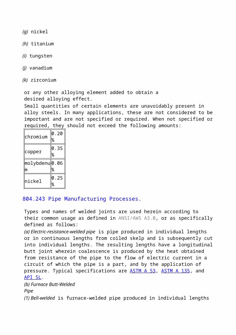
10 lengths or less 1 set of tests from each length11 to 100 lengths 1 set of tests for each 5 lengths, but not less than 10Greater than 100 lengths 1 set of tests for each 10 lengths, but not less than 20(2) All test specimens shall be selected at random.(3) If the yield-tensile ratio exceeds 0.85, the pipe shall not be used, except as provided in para. 817.12.(h) S Value. For pipe of unknown specification, the yield strength, to be used as S in the formula of para. 841.11, in lieu of the specified minimum yield strength, shall be 24,000 psi, or determined as follows.Determine the average value of all yield strength tests for a uniform lot. The value of S shall then be taken as the lesser of the following:(1) 80% of the average value of the yield strength tests(2) the minimum value of any yield strength test, provided, however, that in no case shall S be taken as greater than 52,000 psi(i) Hydrostatic Test. New or used pipe of unknown specification and all used pipe, the strength of which is impaired by corrosion or other deterioration, shall be retested hydrostatically either length by length in a mill-type test or in the field after installation before being placed in service. The test pressure used shall establish the maximum allowable operating pressure, subject to limitations described in para. 841.111.
817.2 Reuse of Ductile Iron Pipe
817.21
The removal of a portion of an existing line of unknown specifications and the reuse of the pipe in the same line or in a line operating at the same or lower pressure is permitted, provided careful inspection indicates that the pipe is sound, permits the makeup of tight joints, and has an actual net wall thickness equal to or exceeding the requirements of para. 842.214. The pipe shall be leak-tested in accordance with para. 841.34 or 841.35.
817.22
Used pipe of known specifications may be reused in accordance with the provisions and specifications of para. 842.2 provided a careful inspection indicates the pipe is sound and permits the makeup of tight joints.
817.3 Reuse of Plastic Piping
Used plastic pipe and tubing of known specifications and dimensions that has been used in natural gas service only may be reused, provided that(a) it meets the requirements of ASTM D 2513 for new thermoplastic pipe or tubing, or ASTM D 2517 for new thermosetting pipe(b) a careful inspection indicates that it is free of visible defects(c) it is installed and tested in accordance with the requirements of this Code for new pipe
CHAPTER II WELDING
820 WELDING
821 GENERAL
(99)821.1 Scope
This Chapter addresses the welding of pipe joints in both wrought and cast steel materials and covers butt and fillet welded joints in pipe, valves, flanges, and fittings and fillet weld joints in pipe branches, slip-on flanges, socket weld fittings, etc., as applied in pipelines and connections to apparatus or equipment. When valves or equipment are furnished with welding ends suitable for welding directly into a pipeline, the design, composition, welding, and stress relief procedures must be such that no significant damage will result from the welding or stress relieving operation. This Chapter does not apply to the welding of the seam in the manufacture of pipe.
821.2
The welding may be done by any process or combination of processes that produce welds that meet the procedure qualification requirements of this Code. The welds may be produced by position welding or roll welding, or a combination of position and roll welding.
821.3
Prior to welding of any pipe, piping components, or related equipment covered by this Code, a welding procedure shall be established and qualified. Each welder or welding operator shall be qualified for the established procedure before performing any welding on any pipe, piping components, or related equipment installed in accordance with this Code.
821.4
The standards of acceptability for welds of piping systems to operate at 20% or more of specified minimum yield strength as established in API 1104 shall be used.
821.5
All welding done under this Code shall be performed under a standard referenced in para. 823.11 or 823.21, whichever is applicable.
821.6
Prior to welding in or around a structure or area containing gas facilities, a thorough check shall be made to determine the possible presence of a combustible gas mixture. Welding shall begin only when safe conditions are indicated.
821.7 Welding Terms
Definitions pertaining to welding as used in this Code conform to the standard definitions established by the American Welding Society and contained in ANSI/AWS A3.0.
822 PREPARATION FOR WELDING
822.1 Butt Welds
(a) Some acceptable end preparations are shown in Appendix I, Fig. I4.(b) Appendix I, Fig. I5 shows acceptable end preparations for buttwelding of pieces having either unequal thickness or unequal yield strength, or both.
822.2 Fillet Welds
Minimum dimensions for fillet welds used in the attachment of slip-on flanges and for socket welded joints are shown in Appendix I, Fig. I6. Similar minimum dimensions for fillet welds used in branch connections are shown in Appendix I, Figs. I1 and I2.
822.3 Seal Welds
Seal welding shall be done by qualified welders. Seal welding of threaded joints is permitted, but the seal welds shall not be considered as contributing to the strength of joints.
823 QUALIFICATION OF PROCEDURES AND WELDERS
823.1 Requirements for Piping Systems Operating at Hoop Stresses of Less Than 20% of the Specified Minimum Yield Strength
823.11
Welders whose work is limited to piping operating at hoop stress levels of less than 20% of the specified minimum yield strength shall be qualified under any of the references given in para. 823.21 or in accordance with Appendix G.
823.2 Requirements for Piping Systems Operating at Hoop Stresses of 20% or More of the Specified Minimum Yield Strength
823.21
Welding procedures and welders performing work under this classification shall be qualified under the ASME Boiler and Pressure Vessel (BPV) Code, Section IX, or API 1104.
823.22
When welders qualified under API 1104 are employed on compressor station piping, their qualification shall have been based on the destructive mechanical test requirements of API 1104.
823.23 Variables for the Separate Qualification of Welders.
The references given in para. 823.21 contain sections titled "Essential Variables," applicable to welder qualification. These shall be followed, except that for purposes of this Code, all carbon
steels that have a carbon content not exceeding 0.32% by heat analysis and a carbon equivalent (C + Mn) not exceeding 0.65% by heat analysis, are considered to come under material grouping P-No. 1. Alloy steels having weldability characteristics demonstrated to be similar to these carbon steels shall be welded, preheated, and stress relieved as prescribed herein for such carbon steel. There may be significant differences in the base metal strength encompassed by these P-No. 1 materials, and although it is not an essential variable to welder qualification, it may require separate procedure qualification in accordance with para. 823.21.
823.3 Welder Requalification Requirements
Welder requalification tests shall be required if there is some specific reason to question a welder's ability or if the welder is not engaged in a given process of welding for 6 months or more. All welders shall be requalified at least once each year.
823.4 Qualification Records
Records of the tests that establish the qualification of a welding procedure shall be maintained as long as that procedure is in use. The operating company or contractor shall, during the construction involved, maintain a record of the welders qualified, showing the dates and results of tests.
824 PREHEATING
824.1
Carbon steels having a carbon content in excess of 0.32% (ladle analysis) or a carbon equivalent (C + Mn) in excess of 0.65% (ladle analysis) shall be preheated to the temperature indicated by the welding procedure. Preheating shall also be required for steels having lower carbon content or carbon equivalents when the welding procedure indicates that chemical composition, ambient and/or metal temperature, material thickness, or weld-end geometry require such treatment to produce satisfactory welds.
824.2
When welding dissimilar materials having different preheating requirements, the material requiring the higher preheat shall govern.
824.3
Preheating may be accomplished by any suitable method, provided that it is uniform and that the temperature does not fall below the prescribed minimum during the actual welding operations.
824.4
The preheating temperature shall be checked by the use of temperature-indicating crayons, thermocouple pyrometers, or other suitable methods to ensure that the required preheat temperature is obtained prior to and maintained during the welding operation.
825 STRESS RELIEVING
825.1
Welds in carbon steels having a carbon content in excess of 0.32% (ladle analysis) or a carbon equivalent (C + Mn) in excess of 0.65% (ladle analysis) shall be stress relieved as prescribed in the ASME BPV Code, Section VIII. Stress relieving may also be advisable for welds in steel having lower carbon content or carbon equivalent when adverse conditions cool the weld too rapidly.
(99)825.2
Welds in all carbon steels shall be stress relieved when the nominal wall thickness exceeds 1 in.
825.3
When the welded joint connects parts that are of different thicknesses but of similar materials, the thickness to be used in applying the rules in paras. 825.1 and 825.2 shall be(a) the thicker of the two parts being joined, measured at the weld joint(b) the thickness of the pipe run or header in case of branch connections, slip-on flanges, or socket weld fittings
825.4
If either material in welds between dissimilar materials requires stress relieving, the joint shall require stress relieving.
825.5
All welding of connections and attachments shall be stress relieved when the pipe is required to be stress relieved by the rules of para. 825.3, with the following exceptions:(a) fillet and groove welds not over -in. leg size that attach connections not over NPS 2 pipe size(b) fillet and groove welds not over in. groove size that attach supporting members or other non-pressure attachments
825.6 Stress Relieving Temperature
(a) Stress relieving shall be performed at a temperature of 1,100°F or greater for carbon steels and 1,200°F or greater for ferritic alloy steels. The exact temperature range shall be stated in the procedure specification.(b) When stress relieving takes place in a joint between dissimilar metals having different stress relieving requirements, the material requiring the higher stress relieving temperature shall govern.(c) The parts heated shall be brought slowly to the required temperature and held at that temperature for a period of time proportioned on the basis of at least 1 hr/in. of pipe wall thickness, but in no case less than hr, and shall be allowed to cool slowly and uniformly.
825.7 Methods of Stress Relieving
(a) Heat the complete structure as a unit.(b) Heat a complete section containing the weld or welds to be stress relieved before attachment to other sections of work.(c) Heat a part of the work by slowly heating a circumferential band containing the weld at the center. The width of the band that is heated to the required temperature shall be at least 2 in. greater than the width of the weld reinforcement. Care should be taken to obtain a uniform temperature around the entire circumference of the pipe. The temperature shall diminish gradually outward from the edges of this band.(d) Branches or other welded attachments for which stress relief is required may be locally stress relieved by heating a circumferential band around the pipe on which the branch or attachment is welded with the attachment at the middle of the band. The width of the band shall be at least 2 in. greater than the diameter of the weld joining the branch or attachment to the header. The entire band shall be brought up to the required temperature and held for the time specified.
825.8 Equipment for Local Stress Relieving
(a) Stress relieving may be accomplished by electric induction, electric resistance, fuel-fired ring burners, fuel-fired torches, or other suitable means of heating, provided that a uniform temperature is obtained and maintained during the stress relieving.(b) The stress relieving temperature shall be checked by the use of thermocouple pyrometers or other suitable equipment to ensure that the proper stress relieving cycle has been accomplished.
826 WELDING AND INSPECTION TESTS
826.1 Inspection of Welds on Piping Systems Intended to Operate at Less Than 20% of the Specified Minimum Yield Strength
The quality of welding shall be checked visually on a sampling basis, and defective welds shall be repaired or removed from the line.
826.2 Inspection and Tests for Quality Control of Welds on Piping Systems Intended to Operate at 20% or More of the Specified Minimum Yield Strength
(a) The quality of welding shall be checked by nondestructive inspection. Nondestructive inspection may consist of radiographic examination, magnetic particle testing, or other acceptable methods. The trepanning method of nondestructive testing is prohibited.(b) The following minimum number of field butt welds shall be selected on a random basis by the operating company from each day's construction for examination. Each weld so selected shall be examined over its entire circumference or else the equivalent length of welds shall be examined if the operating company chooses to examine only a part of the circumference of each. The same minimum percentages shall be examined for double ending at railhead or yard:(1) 10% of welds in Location Class 1(2) 15% of welds in Location Class 2(3) 40% of welds in Location Class 3(4) 75% of welds in Location Class 4(5) 100% of the welds in compressor stations, and at major or navigable river crossings, major
highway crossings, and railroad crossings, if practical, but in no case less than 90%. All tie-in welds not subjected to a pressure proof test shall be examined.(c) All welds that are inspected must either meet the standards of acceptability of API 1104 or be appropriately repaired and reinspected. The results of the inspection shall be used to control the quality of welding.(d) When radiographic examination is employed, a procedure meeting the requirements of API 1104 shall be followed.(e) When pipe size is less than NPS 6, or when the construction project involves such a limited number of welds that nondestructive inspection would be impractical, and the pipe is intended to operate at 40% or less of the specified minimum yield strength, then provisions (a), (b), and (c) above are not mandatory, provided the welding is inspected visually and approved by a qualified welding inspector.(f) In addition to the nondestructive inspection requirements outlined above, the quality of welding shall be continually controlled by qualified personnel.
827 REPAIR OR REMOVAL OF DEFECTIVE WELDS IN PIPING INTENDED TO OPERATE AT 20% OR MORE OF THE SPECIFIED MINIMUM YIELD STRENGTH
Defective welds shall be repaired or removed. If a repair is made, it shall be in accordance with API 1104. Welders performing repairs shall be qualified in accordance with para. 823.2.
CHAPTER III PIPING SYSTEM COMPONENTS AND FABRICATION DETAILS
830 PIPING SYSTEM COMPONENTS AND FABRICATION DETAILS
830.1General
(a) The purpose of this Chapter is to provide a set of standards for piping systems covering(1) specifications for and selection of all items and accessories that are a part of the piping system, other than the pipe itself(2) acceptable methods of making branch connections(3) provisions to care for the effects of temperature changes(4) approved methods for support and anchorage of exposed and buried piping systems(b) This Chapter does not include(1) pipe materials (see Chapter I)(2) welding procedures (see Chapter II)(3) design of pipe (see Chapter IV)(4) installation and testing of piping systems (see Chapter IV)(5) special conditions for offshore application (see Chapter VIII)(99) (6) special conditions for sour gas application (see Chapter IX)
831 PIPING SYSTEM COMPONENTS
All components of piping systems, including valves, flanges, fittings, headers, special assemblies, etc., shall be designed in accordance with the applicable requirements of this Section and recognized engineering practices to withstand operating pressures and other specified loadings.
Selected components shall be designed to withstand the specified field test pressure to which they will be subjected without failure or leakage and without impairment of their serviceability.
831.1 Valves and Pressure Reducing Devices
831.11
Valves shall conform to standards and specifications referenced in this Code and shall be used only in accordance with the service recommendations of the manufacturer.(a) Valves manufactured in accordance with the following standards may be used:
ANSI B16.33 Small Manually Operated Metallic Gas Valves, in Gas Distribution Systems
ANSI B16.34 Steel Valves
ANSI B16.38 Large Manually Operated Metallic Gas Valves in Gas Distribution Systems
ANSI/ASME B16.40 Manually Operated Thermoplastic Gas Shut-Offs and Valves in Gas Distribution Systems
API 6A Wellhead Equipment
API 6D Pipeline Valves
MSS SP-70 Cast Iron Gate Valves
MSS SP-71 Cast Iron Swing Check Valves
MSS SP-78 Cast Iron Plug Valves
(b) Valves having shell (body, bonnet, cover, and/or end flange) components made of cast ductile iron in compliance with ASTM A 395 and having dimensions conforming to ANSI B16.1, ANSI B16.33, ANSI B16.34, ANSI B16.38, API 6D, or ASME B16.40 may be used at pressures not exceeding 80% of the pressure ratings for comparable steel valves at their listed temperature, provided the pressure does not exceed 1,000 psi, and welding is not employed on any ductile iron component in the fabrication of the valve shells or their assembly as part of the piping system.(c) Valves having shell components made of cast iron shall not be used in gas piping components for compressor stations.
831.12
Threaded valves shall be threaded according to ANSI B1.20.1, API 5L, or API 6A.
831.13
Pressure reducing devices shall conform to the requirements of this Code for valves in comparable
service conditions.
831.2 Flanges
831.21 Flange Types and Facings
(a) The dimensions and drilling for all line or end flanges shall conform to one of the following standards:
ANSI B16 Series listed in Appendices A and B (for Iron and Steel)
MSS SP-44 Steel Pipe Line Flanges
Appendix I Light-Weight Steel Flanges
ANSI B16.24 Brass or Bronze Flanges and Flanged Fittings
Flanges cast or forged integral with pipe, fittings, or valves are permitted in sizes and the pressure classes covered by the standards listed above, subject to the facing, bolting, and gasketing requirements of this paragraph and paras. 831.22 and 831.23.(b) Threaded companion flanges that comply with the B16 group of American National Standards are permitted in sizes and pressure classes covered by these standards.(c) Lapped flanges are permitted in sizes and pressure classes established in ANSI B16.5.(d) Slip-on welding flanges are permitted in sizes and pressure classes established in ANSI B16.5. Slip-on flanges of rectangular section may be substituted for hubbed slip-on flanges, provided the thickness is increased as required to produce equivalent strength as determined by calculations made in accordance with Section VIII of the BPV Code.(e) Welding neck flanges are permitted in sizes and pressure classes established in ANSI B16.5 and MSS SP-44. The bore of the flange should correspond to the inside diameter of the pipe used. For permissible welding end treatment, see Appendix I, Fig. I5.(f) Cast iron, ductile iron, and steel flanges shall have contact faces finished in accordance with MSS SP-6.(g) Nonferrous flanges shall have contact faces finished in accordance with ANSI B16.24.(h) Class 25 and 125 cast iron integral or threaded companion flanges may be used with a full-face gasket or with a flat ring gasket extending to the inner edge of the bolt holes. When using a full-face gasket, the bolting may be of alloy steel (ASTM A 193). When using a ring gasket, the bolting shall be of carbon steel, equivalent to ASTM A 307 Grade B, without heat treatment other than stress relief.(i) When bolting together two Class 250 integral or threaded companion cast iron flanges having 1/16-in. raised faces, the bolting shall be of carbon steel equivalent to ASTM A 307 Grade B, without heat treatment other than stress relief.(j) Class 150 steel flanges may be bolted to Class 125 cast iron flanges. When such construction is used, the 1/16-in. raised face on the steel flange shall be removed. When bolting such flanges together using a flat ring gasket extending to the inner edge of the bolt holes, the bolting shall be of carbon steel equivalent to ASTM A 307 Grade B, without heat treatment other than stress relief. When bolting such flanges together using a full-face gasket, the bolting may be alloy steel (ASTM A 193).(k) Class 300 steel flanges may be bolted to Class 250 cast iron flanges. Where such construction is
used, the bolting shall be of carbon steel, equivalent to ASTM A 307 Grade B, without heat treatment other than stress relief. Good practice indicates that the raised face on the steel flange should be removed, but also in this case, bolting shall be of carbon steel equivalent to ASTM A 307 Grade B.(l) Forged steel welding neck flanges having an outside diameter and drilling the same as that of ANSI B16.1, but with modified flange thickness, hub dimensions, and special facing details, may be used to bolt against flat faced cast iron flanges and may operate at the pressure-temperature ratings given in ANSI B16.1 for Class 125 cast iron pipe flanges, provided(1) the minimum flange thickness, T, is not less than that specified in Appendix I for lightweight flanges(2) flanges are used with nonmetallic full-face gaskets extending to the periphery of the flange(3) the joint design has been proven by test to be suitable for the ratings(m) Flanges made of ductile iron shall conform to the requirements of ANSI B16.42. Bolting requirements for ductile iron flange joints shall be the same as those for carbon and low alloy steel flanges as specified in para. 831.22.
831.22 Bolting
(a) For all flange joints, the bolts or studbolts used shall extend completely through the nuts.(b) For all flange joints other than those described in paras. 831.21(h), (i), (j), and (k), the bolting shall be made of alloy steel conforming to ASTM A 193, ASTM A 320, or ASTM A 354, or of heat treated carbon steel conforming to ASTM A 449. Bolting, however, for ANSI B16.5 Class 150 and 300 flanges at temperatures between -20°F and 450°F may be made of Grade B of ASTM A 307.(c) Alloy-steel bolting material conforming to ASTM A 193 or ASTM A 354 shall be used for insulating flanges if such bolting is made -in. undersized.(d) The materials used for nuts shall conform to ASTM A 194 and ASTM A 307. ASTM A 307 nuts may be used only with ASTM A 307 bolting.(e) All carbon and alloy-steel bolts, studbolts, and their nuts shall be threaded in accordance with the following thread series and dimension classes as required by ANSI B1.1.(1) Carbon Steel. All carbon-steel bolts and stud-bolts shall have coarse threads having Class 2A dimensions, and their nuts shall have Class 2B dimensions.(2) Alloy Steel. All alloy-steel bolts and studbolts of 1-in. and smaller nominal diameter shall be of the coarse-thread series; nominal diameters 1 in. and larger shall be of the 8-thread series. Bolts and studbolts shall have a Class 2A dimension; their nuts shall have Class 2B dimension.(f) Bolts shall have American National Standard regular square heads or heavy hexagonal heads and shall have American National Standard heavy hexagonal nuts conforming to the dimensions of ANSI B18.2.1 and B18.22.(g) Nuts cut from bar stock in such a manner that the axis will be parallel to the direction of rolling of the bar may be used in all sizes for joints in which one or both flanges are cast iron and for joints with steel flanges where the pressure does not exceed 250 psig. Such nuts shall not be used for joints in which both flanges are steel and the pressure exceeds 250 psig, except that for nut sizes in. and smaller, these limitations do not apply.
831.23 Gaskets
(a) Material for gaskets shall be capable of withstanding the maximum pressure and of maintaining its physical and chemical properties at any temperature to which it might reasonably be subjected in
service.(b) Gaskets used under pressure and at temperatures above 250°F shall be of noncombustible material. Metallic gaskets shall not be used with Class 150 standard or lighter flanges.(c) Asbestos composition gaskets may be used as permitted in ANSI B16.5. This type of gasket may be used with any of the various flanged facings except small male and female or small tongue and groove.(d) The use of metal or metal-jacketed asbestos gaskets (either plain or corrugated) is not limited as to pressure, provided that the gasket material is suitable for the service temperature. These types of gaskets are recommended for use with the small male and female or the small tongue and groove facings. They may also be used with steel flanges with lapped, large male and female, large tongue and groove, or raised face facings.(e) Full-face gaskets shall be used with all bronze flanges and may be used with Class 25 or 125 cast iron flanges. Flat ring gaskets with an outside diameter extending to the inside of the bolt holes may be used with cast iron flanges, with raised face steel flanges, or with lapped steel flanges.(f) To secure higher unit compression on the gasket, metallic gaskets of a width less than the full male face of the flange may be used with raised face, lapped, or large male and female facings. The width of the gasket for small male and female or for tongue and groove joints shall be equal to the width of the male face or tongue.(g) Rings for ring joints shall be of dimensions established in ANSI B16.20. The material for these rings shall be suitable for the service conditions encountered and shall be softer than the flanges.(h) The insulating material shall be suitable for the temperature, moisture, and other conditions where it will be used.
831.3 Fittings Other Than Valves and Flanges
831.31 Standard Fittings
(a) The minimum metal thickness of flanged or threaded fittings shall not be less than specified for the pressures and temperatures in the applicable American National Standards or the MSS Standard Practice.(b) Steel buttwelding fittings shall comply with either ANSI B16.9 or MSS SP-75 and shall have pressure and temperature ratings based on stresses for pipe of the same or equivalent material. For adequacy of fitting design, the actual bursting strength of fittings shall at least equal the computed bursting strength of pipe of the designated material and wall thickness. Mill hydrostatic testing of factory-made steel buttwelding fittings is not required, but all such fittings shall be capable of withstanding a field test pressure equal to the test pressure established by the manufacturer, with-out failure or leakage, and without impairment of their serviceability.(c) Steel socket-welding fittings shall comply with ANSI B16.11.(d) Ductile iron flanged fittings shall comply with the requirements of ANSI B16.42 or ANSI A21.14.(e) Thermoplastic fittings shall comply with ASTM D 2513.(f) Reinforced thermosetting plastic fittings shall comply with ASTM D 2517.
831.32 Special Fittings.
When special cast, forged, wrought, or welded fittings are required to dimensions differing from those of regular shapes specified in the applicable American National and MSS Standards, the provisions of para. 831.36 shall apply.
831.33 Branch Connections
(a) Welded branch connections on steel pipe must meet the design requirements of paras. 831.4 and 831.5.(b) Threaded taps in cast iron pipe for branch connections are permitted without reinforcement to a size not more than 25% of the nominal diameter of the pipe; however, where climate service conditions or soil conditions create abnormal or unusual external loadings on cast iron pipe, unreinforced threaded taps for branch connections are permitted only on cast iron pipe NPS 8 and larger in diameter, provided that the tap size is no greater than 25% of the nominal pipe diameter.(c) Existing threaded taps in cast iron pipe may be used for replacement branch connections when careful inspection shows there are no cracks or other deterioration in the main immediately surrounding the opening.(d) Threaded taps in ductile iron pipe are permitted without reinforcement to a size not more than 25% of the nominal diameter of the pipe, except that 1 -in. taps are permitted in NPS 4 pipe having a nominal wall thickness of not less than 0.380 in.(e) Mechanical fittings may be used for making hot taps on pipelines and mains provided they are designed for the operating pressure of the pipeline or main, and are suitable for the purpose.
831.34 Openings for Gas Control Equipment in Cast Iron Pipe.
Threaded taps used for gas control equipment in cast iron pipe (i.e., bagging off a section of main) are permitted without reinforcement, to a size not more than 25% of the nominal diameter of the pipe, except that 1 -in. taps are permitted in NPS 4 pipe. Taps larger than those permitted above shall use a reinforcing sleeve.
831.35 Special Components Fabricated by Welding
(a) This section covers piping system components other than assemblies consisting of pipe and fittings joined by circumferential welds.(b) All welding shall be performed using procedures and operators that are qualified in accordance with the requirements of para. 823.(c) Branch connections shall meet the design requirements of paras. 831.4, 831.5, and 831.6.(d) Prefabricated units, other than regularly manufactured buttwelding fittings, that employ plate and longitudinal seams as contrasted with pipe that has been produced and tested under one of the specifications listed in this Code, shall be designed, constructed, and tested under requirements of the BPV Code. BPV Code requirements are not intended to apply to such partial assemblies as split rings or collars or to other field welded details.(e) Every prefabricated unit produced under this section of the Code shall successfully withstand a pressure test without failure, leakage, distress, or distortion other than elastic distortion at a pressure equal to the test pressure of the system in which it is installed, either before installation or during the system test. When such units are to be installed in existing systems, they shall be pressure tested before installation, if feasible; otherwise, they shall withstand a leak test at the operating pressure of the line.
831.36 Pressure Design of Other Pressure-Containing Components.
Pressure-containing components that are not covered by the standards listed in Appendix A and for which design equations or procedures are not given herein may be used where the design of
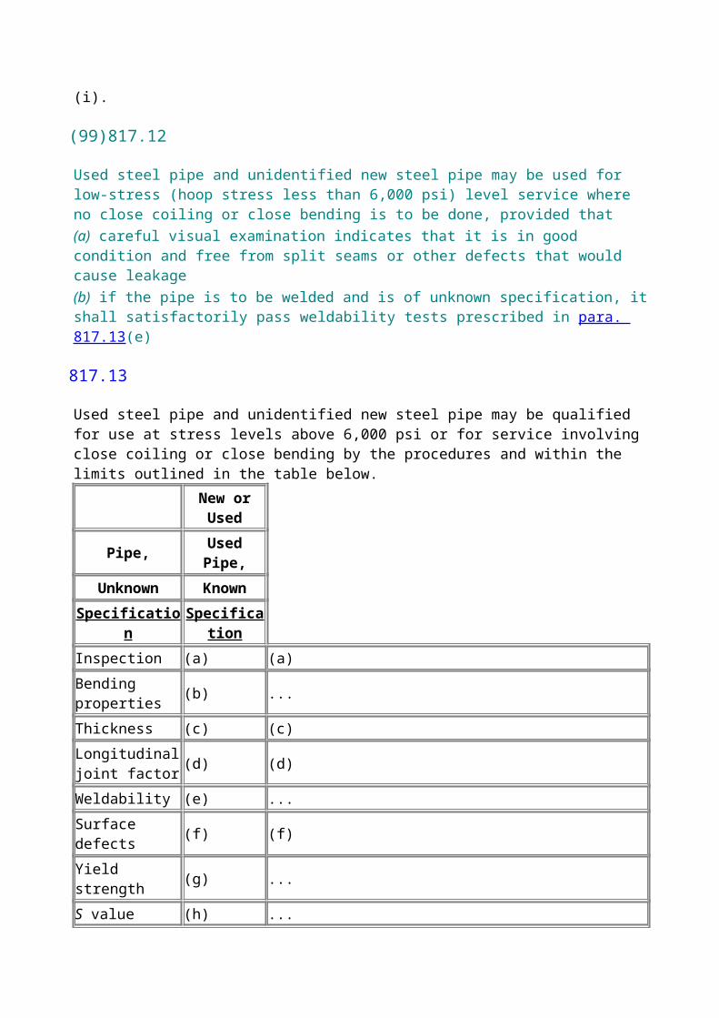
similarly shaped, proportioned, and sized components has been proven satisfactory by successful performance under comparable service conditions. (Interpolation may be made between similarly shaped components with small differences in size or proportion.) In the absence of such service experience, the pressure design shall be based on an analysis consistent with the general design philosophy embodied in this Code and substantiated by at least one of the following:(a) proof tests, as described in UG-101 of Section VIII, Division 1, of the BPV Code(b) experimental stress analysis, as described in Appendix 6 of Section VIII, Division 2, of the BPV Code(c) engineering calculations
831.37 Closures
831.371 Quick Opening Closures.
A quick opening closure is a pressure-containing component (see para. 831.36) used for repeated access to the interior of a piping system. It is not the intent of this Code to impose the requirements of a specific design method on the designer or manufacturer of a quick opening closure.Quick opening closures shall have pressure and temperature ratings equal to or in excess of the design requirements of the piping system to which they are attached.Quick opening closures shall be equipped with safety locking devices in compliance with Section VIII, Division 1, UG-35(b) of the BPV Code.Weld end preparation shall be in accordance with Appendix I, Fig. I4.
831.372 Closure Fittings.
Closure fittings commonly referred to as "weld caps" shall be designed and manufactured in accordance with ANSI B16.9 or MSS SP-75. [See para. 831.31(b).]
831.373 Closure Heads.
Closure heads such as flat, ellipsoidal (other than in para. 831.372), spherical, or conical heads are allowed for use under this Code. Such items may be designed in accordance with Section VIII, Division 1, of the BPV Code. The maximum allowable stresses for materials used in these closure heads shall be established under the provisions of para. 841 not exceeding 60% SMYS.If welds are used in the construction of these heads, they shall be inspected in accordance with the provision of Section VIII, Division 1 of the BPV Code.Closure heads shall have pressure and temperature ratings equal to or in excess of the design requirement of the piping system to which they are attached.
831.374 Fabricated Closures.
Orange-peel bull plugs and orange-peel swages are prohibited on systems operating at stress levels of 20% or more of the specified minimum yield strength of the pipe material. Fish tails and flat closures are permitted on pipe NPS 3 and smaller operating at less than 100 psi. Fish tails on pipe larger than NPS 3 are prohibited. Flat closures on pipe larger than NPS 3 shall be designed according to Section VIII, Division 1, of the BPV Code. (See para. 831.373.)
831.375 Bolted Blind Flange Connections.
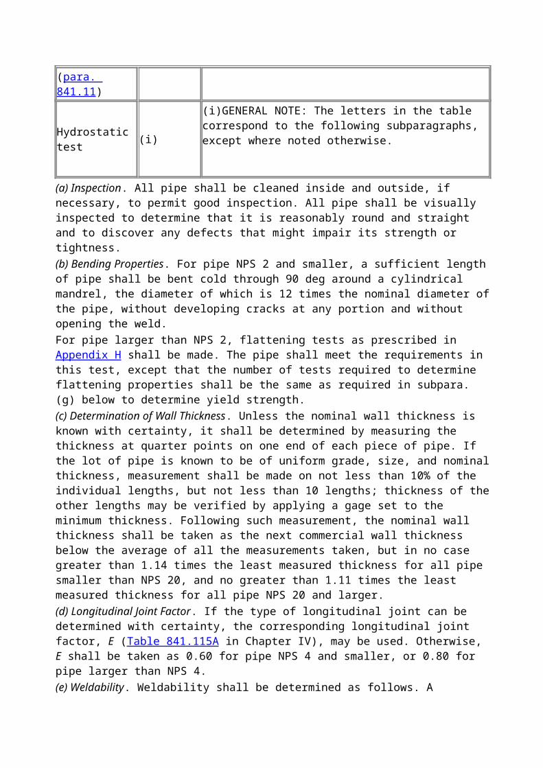
Bolted blind flange connections shall conform to para. 831.2.
831.4 Reinforcement of Welded Branch Connections
831.41 General Requirements.
All welded branch connections shall meet the following requirements.(a) When branch connections are made to pipe in the form of a single connection or in a header or manifold as a series of connections, the design must be adequate to control the stress levels in the pipe within safe limits. The construction shall accommodate the stresses in the remaining pipe wall due to the opening in the pipe or header, the shear stresses produced by the pressure acting on the area of the branch opening, and any external loadings due to thermal movement, weight, vibration, etc. The following paragraphs provide design rules for the usual combinations of the above loads, except for excessive external loads.(b) The reinforcement required in the crotch section of a welded branch connection shall be determined by the rule that the metal area available for reinforcement shall be equal to or greater than the required area as defined in this paragraph as well as in Appendix F, Fig. F5.(c) The required cross-sectional area, AR, is defined as the product of d times t:
where
d = the greater of the length of the finished opening in the header wall measured parallel to the axis of the run or the inside diameter of the branch connection
t = the nominal header wall thickness required by para. 841.11 for the design pressure and temperature
When the pipe wall thickness includes an allowance for corrosion or erosion, all dimensions used shall result after the anticipated corrosion or erosion has taken place.(d) The area available for reinforcement shall be the sum of(1) the cross-sectional area resulting from any excess thickness available in the header thickness over the minimum required for the header as defined in para. 831.41(c) and that lies within the reinforcement area as defined in para. 831.41(e)(2) the cross-sectional area resulting from any excess thickness available in the branch wall thickness over the minimum thickness required for the branch and that lies within the reinforcement area as defined in para. 831.41(e)(3) the cross-sectional area of all added reinforcing metal that lies within the reinforcement area, as defined in para. 831.41(e), including that of solid weld metal that is conventionally attached to the header and/or branch(e) The area of reinforcement, shown in Appendix F, Fig. F5, is defined as a rectangle whose length shall extend a distance, d, on each side of the transverse center line of the finished opening and whose width shall extend a distance of 2 times the header wall thickness on each side of the surface of the header wall. In no case, however, shall it extend more than 2 times the thickness of the branch wall from the outside surface of the header or of the reinforcement, if any.(f) The material of any added reinforcement shall have an allowable working stress at least equal to that of the header wall, except that material of lower allowable stress may be used if the area is increased in direct ratio of the allowable stress for header and reinforcement material, respectively.(g) The material used for ring or saddle reinforcement may be of specifications differing from those
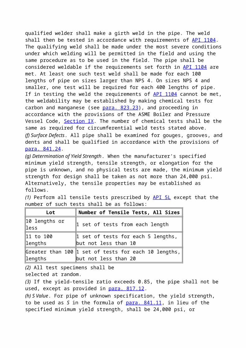
of the pipe, provided the cross-sectional area is made in direct proportion to the relative strength of the pipe and reinforcement materials at the operating temperatures, and provided it has welding qualities comparable to those of the pipe. No credit shall be taken for the additional strength of material having a higher strength than that of the part to be reinforced.(h) When rings or saddles cover the weld between branch and header, a vent hole shall be provided in the ring or saddle to reveal leakage in the weld between branch and header and to provide venting during welding and heat treating operations. Vent holes should be plugged during service to prevent crevice corrosion between pipe and reinforcing member, but no plugging material that would be capable of sustaining pressure within the crevice should be used.(i) The use of ribs or gussets shall not be considered as contributing to reinforcement of the branch connection. This does not prohibit the use of ribs or gussets for purposes other than reinforcement, such as stiffening.(j) The branch shall be attached by a weld for the full thickness of the branch or header wall plus a fillet weld, W1, as shown in Appendix I, Figs. I1 and I2. The use of concave fillet welds is preferred to further minimize corner stress concentration. Ring or saddle reinforcement shall be attached as shown by Fig. I2. When a full fillet is not used, it is recommended that the edge of the reinforcement be relieved or chamfered at approximately 45 deg to merge with the edge of the fillet.(k) Reinforcement rings and saddles shall be accurately fitted to the parts to which they are attached. Appendix I, Figs. I2 and I3 illustrate some acceptable forms of reinforcement.(l) Branch connections attached at an angle less than 85 deg to the run become progressively weaker as the angle decreases. Any such design must be given individual study, and sufficient reinforcement must be provided to compensate for the inherent weakness of such construction. The use of encircling ribs to support the flat or reentering surfaces is permissible and may be included in the strength calculations. The designer is cautioned that stress concentrations near the ends of partial ribs, straps, or gussets may defeat their reinforcing value.
831.42 Special Requirements.
In addition to the requirements of para. 831.41, branch connections must meet the special requirements of the following paragraphs as given in Table 831.42.(a) Smoothly contoured wrought steel tees of proven design are preferred. When tees cannot be used, the reinforcing member shall extend around the circumference of the header. Pads, partial saddles, or other types of localized reinforcement are prohibited.(b) Smoothly contoured tees of proven design are preferred. When tees are not used, the reinforcing member should be of the complete encirclement type, but may be of the pad type, saddle type, or a welding outlet fitting type.(c) The reinforcement member may be of the complete encirclement type, pad type, saddle type, or
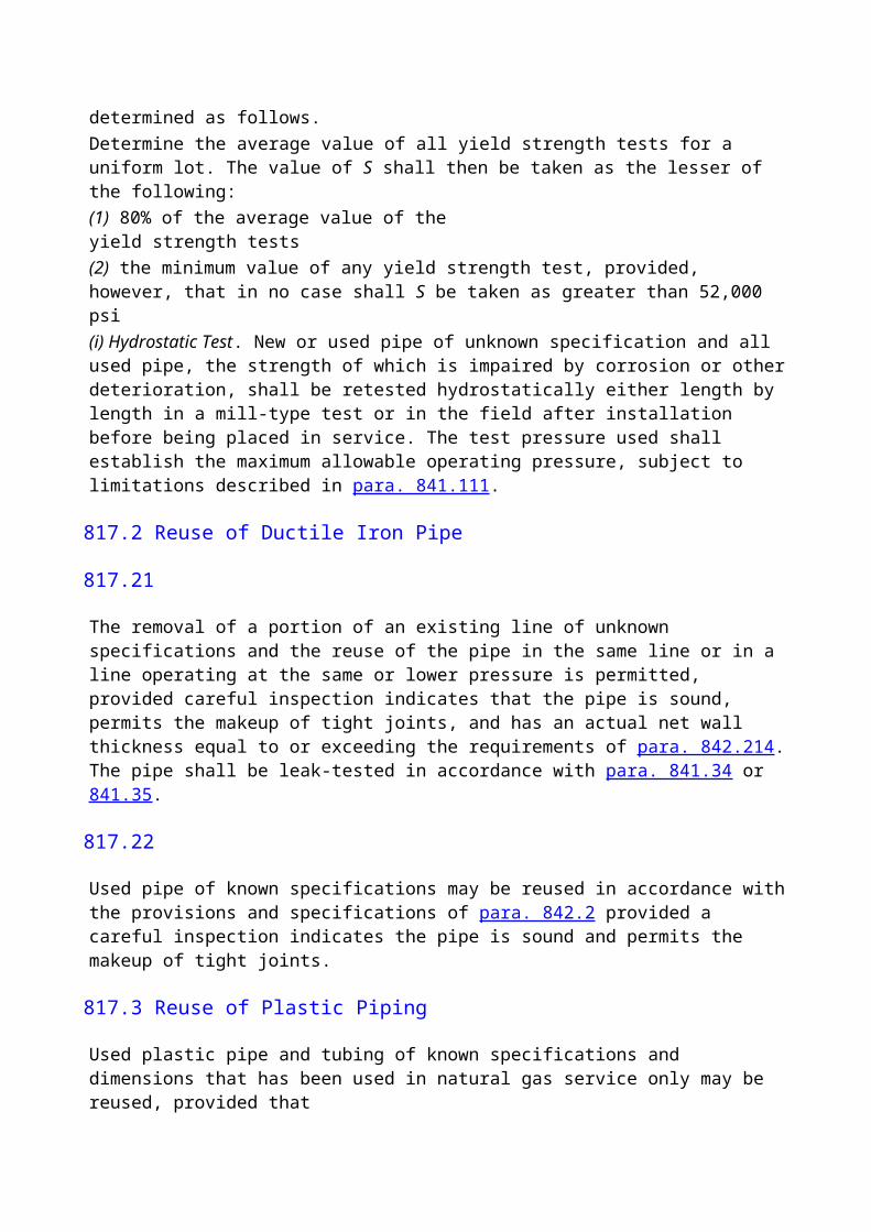
welding outlet fitting type. The edges of reinforcement members should be tapered to the header thickness. It is recommended that legs of fillet welds joining the reinforcing member and header do not exceed the thickness of the header.(d) Reinforcement calculations are not required for openings 2 in. and smaller in diameter; however, care should be taken to provide suitable protection against vibrations and other external forces to which these small openings are frequently subjected.(e) All welds joining the header, branch, and reinforcing member shall be equivalent to those shown in Appendix I, Figs. I1 and I2.(f) The inside edges of the finished opening shall, whenever possible, be rounded to a -in. radius. If the encircling member is thicker than the header and is welded to the header, the ends shall be tapered down to the header thickness, and continuous fillet welds shall be made.(g) Reinforcement of openings is not mandatory; however, reinforcement may be required for special cases involving pressures over 100 psi, thin wall pipe, or severe external loads.(h) If a reinforcement member is required, and the branch diameter is such that a localized type of reinforcement member would extend around more than half the circumference of the header, then a complete encirclement type of reinforcement member shall be used, regardless of the design hoop stress, or a smoothly contoured wrought steel tee of proven design may be used.(i) The reinforcement may be of any type meeting the requirements of para. 831.41.
831.5 Reinforcement of Multiple Openings
831.51
When two or more adjacent branches are spaced at less than two times their average diameter (so that their effective areas of reinforcement overlap), the group of openings shall be reinforced in accordance with para. 831.4. The reinforcing metal shall be added as a combined reinforcement, the strength of which shall equal the combined strengths of the reinforcements that would be required for the separate openings. In no case shall any portion of a cross section be considered to apply to more than one opening or be evaluated more than once in a combined area.
831.52
When more than two adjacent openings are to be provided with a combined reinforcement, the minimum distance between centers of any two of these openings shall preferably be at least 1 times their average diameter, and the area of reinforcement between them shall be at least equal to 50% of the total required for these two openings on the cross section being considered.
831.53
When the distance between centers of two adjacent openings is less than 1 times their average diameter, as considered under para. 831.52, no credit for reinforcement shall be given for any of the metal between these two openings.
831.54
Any number of closely spaced adjacent openings in any arrangement may be reinforced as if the group were treated as one assumed opening of a diameter enclosing all such openings.
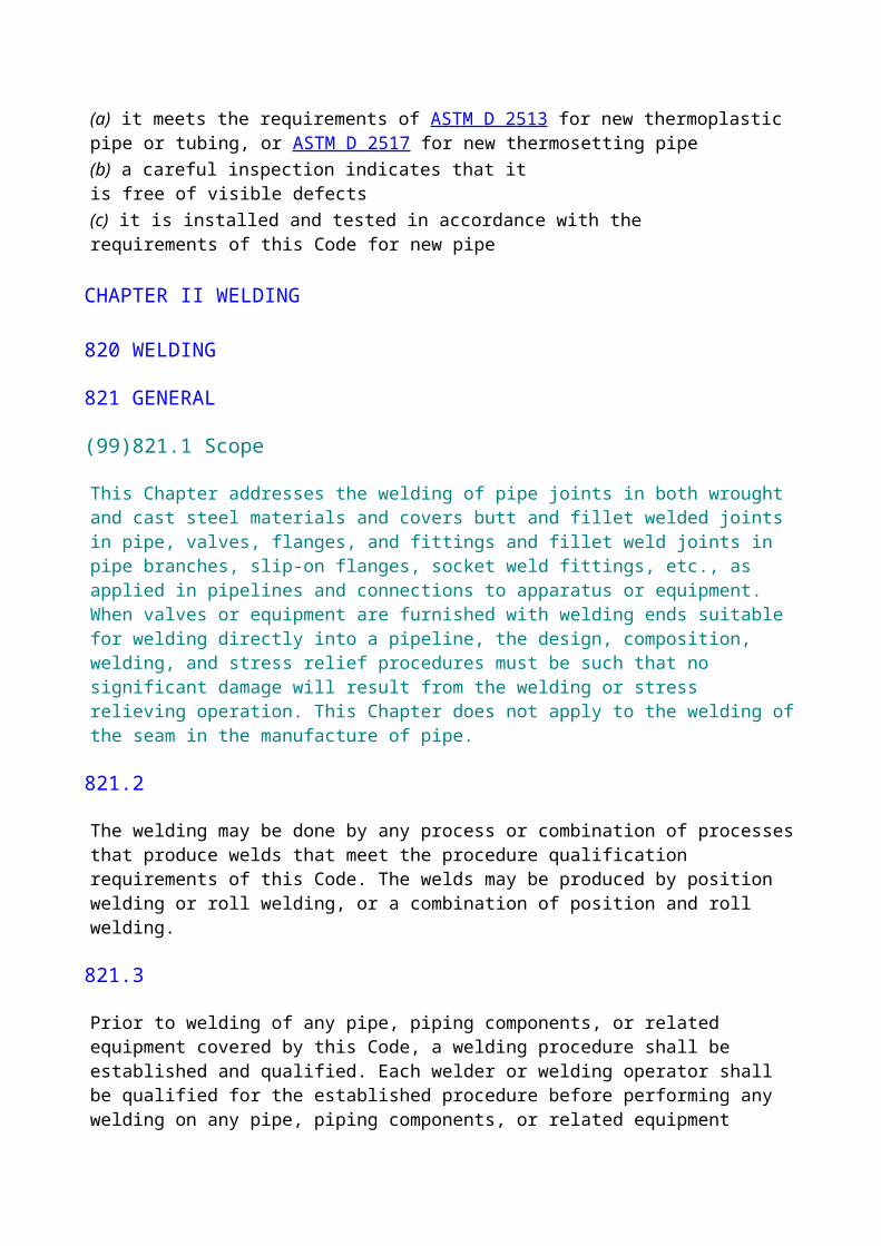
831.6 Extruded Outlets
(a) The rules in this paragraph apply to steel extruded outlets in which the reinforcement is integral.An extruded outlet is defined as an outlet in which the extruded lip at the outlet has a height above the surface of the run that is equal to or greater than the radius of curvature of the external contoured portion of the outlet. (See Appendix F, Figs. F1 through F4 and nomenclature.)(b) These rules do not apply to any nozzles or branch connections in which additional nonintegral material is applied in the form of rings, pads, or saddles.(c) These rules apply only to cases where the axis of the outlet intersects and is perpendicular to the axis of the run.(d) Figures F1 through F4 define the pertinent dimensions and limiting conditions.(e) Required Area. The required area is defined as
where
K = 1.00 when d/D > 0.60
= 0.6 + d/D > 0.15 and not exceeding 0.60
= 0.70 when d/D 0.15The design must meet the criterion that the reinforcement area defined in subpara. (f) below is not less than the required area.(f) Reinforcement Area. The reinforcement area shall be the sum of areas A1 + A2 + A3 as defined below.(1) Area A1 is the area lying within the reinforcement zone resulting from any excess thickness available in the run wall, i.e.,
(2) Area A2 is the area lying within the reinforcement zone resulting from any excess thickness available in the branch pipe wall, i.e.,
(3) Area A3 is the area lying within the reforcement zone resulting from excess thickness available in the extruded outlet lip, i.e.,
(g) Reinforcement of Multiple Openings. The rules in para. 831.5 shall be followed, except that the required area and reinforcement area shall be as given in para. 831.6.
(h) In addition to the above, the manufacturer shall be responsible for establishing and marking on the section containing extruded outlets the following: the design pressure, temperature, and that these were established under provisions of this Code. The manufacturer's name or trademark shall be marked on the section.
832 EXPANSION AND FLEXIBILITY
832.1 Scope
This section is applicable to above ground piping only and covers all classes of materials permitted by this Code up to temperatures no greater than 450°F.
832.2 Amount of Expansion
The thermal expansion of the more common materials used for piping shall be determined from Table 832.2. The expansion to be considered is the difference between the expansion for the maximum expected operating temperature and that for the expected average erection temperature. For materials not included in this Table, or for precise calculations, reference shall be made to authoritative source data, such as publications of the National Institute of Standards and Technology.
832.3 Flexibility Requirements
832.31
Piping systems shall be designed to have sufficient flexibility to prevent thermal expansion or contraction from causing excessive stresses in the piping material, excessive bending or unusual loads at joints, or undesirable forces or moments at points of connection to equipment or at anchorage or guide points. Formal calculations shall be required only where reasonable doubt exists as to the adequate flexibility of the system.
832.32
Flexibility shall be provided by the use of bends, loops, or offsets, or provision shall be made to absorb thermal changes by the use of expansion joints or couplings of the slip joint type or expansion joints of the bellows type. If expansion joints are used, anchors or ties of sufficient strength and rigidity shall be installed to provide for end forces due to fluid pressure and other causes.
832.33
In calculating the flexibility of a piping system, the system shall be treated as a whole. The significance of all parts of the line and all restraints, such as solid supports or guides, shall be considered.
832.34
Calculations shall account for stress intensification factors found to exist in components other than
plain straight pipe. Credit may be taken for the extra flexibility of such components. In the absence of more directly applicable data, the flexibility factors and stress intensification factors shown in Table E1 of Appendix E may be used.
832.35
Properties of pipe and fittings for these calculations shall be based on nominal dimensions, and the joint factor, E (Table 841.115A), shall be taken as 1.00.
832.36
The total range in temperature shall be used in all expansion calculations, whether piping is cold-sprung or not. In addition to the expansion of the line itself, the linear and angular movements of the equipment to which it is attached shall be considered.
832.37 Cold-Springing.
To modify the effect of expansion and contraction, runs of pipe may be cold-sprung. Cold-spring may be taken into account in the calculations of the reactions as shown in para. 833.5, provided an effective method of obtaining the designed cold-spring is specified and used.
832.38
Flexibility calculations shall be based on the modulus of elasticity, Ec, at ambient temperature.
833 COMBINED STRESS CALCULATIONS
833.1
Using the above assumptions, the stresses and reactions due to expansion shall be investigated at all significant points.
833.2
The expansion stresses shall be combined in accordance with the following formula:
where
Mb = resultant bending moment, lb-in.
Mt = torsional moment, lb-in.
SE = combined expansion stress, psi
Sb = resultant bending stress, psi
= iM b / z
St = torsional stress, psi
= M t / 2z
i = stress intensification factor (Appendix E)
z = section modulus of pipe, in.3
833.3
The maximum combined expansion stress range, SE, shall not exceed 0.72S, where S is the specified minimum yield strength, psi, subject to the further limitation of para. 833.4.
833.4
The total of the following shall not exceed the specified minimum yield strength, S:(a) the combined stress due to expansion, SE
(b) the longitudinal pressure stress (see para. 841.11, SFT)(c) the longitudinal bending stress due to external loads, such as weight of pipe and contents, wind, etc.The sum of paras. 833.4(b) and (c) shall not exceed 0.75S.
833.5
The reaction, R , shall be obtained as follows from the reactions R derived from the flexibility calculations:
when CS is less than 0.6; R = CS when CS is between 0.6 and 1.0
where
CS = the cold-spring factor varying from 0 for no cold-spring to 1.0 for 100% cold-spring
EC = the modulus of elasticity in the cold condition
R = maximum reaction corresponding to the full expansion range based on EC
R = maximum reaction for the line after cold-springing; the reactions so computed shall not exceed limits that the attached equipment or anchorage is designed to sustain
834 SUPPORTS AND ANCHORAGE FOR EXPOSED PIPING
834.1 General
Piping and equipment shall be supported in a substantial and workmanlike manner, so as to prevent or reduce excessive vibration, and shall be anchored sufficiently to prevent undue strains on connected equipment.
834.2 Provision for Expansion
Supports, hangers, and anchors should be so installed as not to interfere with the free expansion and
contraction of the piping between anchors. Suitable spring hangers, sway bracing, etc., shall be provided where necessary.
834.3 Materials, Design, and Installation
All permanent hangers, supports, and anchors shall be fabricated from durable incombustible materials and designed and installed in accordance with good engineering practice for the service conditions involved. All parts of the supporting equipment shall be designed and installed so that they will not be disengaged by movement of the supported piping.
834.4 Forces on Pipe Joints
(a) All exposed pipe joints shall be able to sustain the maximum end force due to the internal pressure, i.e., the design pressure (psi) times the internal area of the pipe (sq in.) as well as any additional forces due to temperature expansion or contraction or to the weight of pipe and contents.(b) If compression or sleeve-type couplings are used in exposed piping, provision shall be made to sustain the longitudinal forces noted in subpara. (a) above. If such provision is not made in the manufacture of the coupling, suitable bracing or strapping shall be provided, but such design must not interfere with the normal performance of the coupling nor with its proper maintenance. Attachments must meet the requirements of para. 834.5.
834.5 Attachment of Supports or Anchors
(a) If the pipe is designed to operate at a hoop stress of less than 50% of the specified minimum yield strength, structural supports or anchors may be welded directly to the pipe. Proportioning and welding strength requirements of such attachments shall conform to standard structural practice.(b) If the pipe is designed to operate at a hoop stress of 50% or more of the specified minimum yield strength, support of the pipe shall be furnished by a member that completely encircles it. Where it is necessary to provide positive attachment, as at an anchor, the pipe may be welded to the encircling member only; the support shall be attached to the encircling member and not to the pipe. The connection of the pipe to the encircling member shall be by continuous welds, rather than intermittent ones.
835 ANCHORAGE FOR BURIED PIPING
835.1 General
Bends or offsets in buried pipe cause longitudinal forces that must be resisted by anchorage at the bend, by restraint due to friction of the soil, or by longitudinal stresses in the pipe.
835.2 Anchorage at Bends
If the pipe is anchored by bearing at the bend, care shall be taken to distribute the load on the soil so that the bearing pressure is within safe limits for the soil involved.
835.3 Restraint Due to Soil Friction
Where there is doubt as to the adequacy of restraint friction, calculations shall be made, and
indicated anchoring shall be installed.
835.4 Forces on Pipe Joints
If anchorage is not provided at the bend (see para. 835.2), pipe joints that are close to the points of thrust origin shall be designed to sustain the longitudinal pullout force. If such provision is not made in the manufacture of the joints, suitable bracing or strapping shall be provided.
835.5 Supports for Buried Piping
In pipelines, especially those that are highly stressed from internal pressure, uniform and adequate support of the pipe in the trench is essential. Unequal settlements may produce added bending stresses in the pipe. Lateral thrusts at branch connections may greatly increase the stresses in the branch connection itself, unless the fill is thoroughly consolidated or other provisions are made to resist the thrust.Rock shield shall not be draped over the pipe unless suitable backfill and padding are placed in the ditch to provide a continuous and adequate support of the pipe in the trench.
835.51
When openings are made in a consolidated backfill to connect new branches to an existing line, care must be taken to provide firm foundation for both the header and the branch to prevent vertical and lateral movements.
835.6 Interconnection of Underground Lines
Underground lines are subjected to longitudinal stresses due to changes in pressure and temperature. For long lines, the friction of the earth will prevent changes in length from these stresses, except for several hundred feet adjacent to bends or ends. At these locations, the movement, if unrestrained, may be of considerable magnitude. If connections are made at such a location to a relatively unyielding line or other fixed object, it is essential that the interconnection shall have ample flexibility to compensate for possible movement, or the line shall be provided with an anchor sufficient to develop the forces necessary to limit the movement.
CHAPTER IV DESIGN, INSTALLATION, AND TESTING
840 DESIGN, INSTALLATION, AND TESTING
840.1 General Provisions
(a) The design requirements of this Code are intended to be adequate for public safety under all conditions encountered in the gas industry. Conditions that may cause additional stress in any part of a line or its appurtenances shall be provided for, using good engineering practice. Examples of such conditions include long self-supported spans, unstable ground, mechanical or sonic vibration, weight of special attachments, earthquake-induced stresses, stresses caused by temperature differences, and the soil and temperature conditions found in the Arctic. Temperature differences shall be taken as the difference between the lowest and highest expected metal temperature during pressure test and/or operating services having due regard to past recorded temperature data and the
possible effects of lower or higher air and ground temperature.(b) The most significant factor contributing to the failure of a gas pipeline is damage to the line caused by the activities of people along the route of the line. Damage will generally occur during construction of other facilities associated with providing the services associated with human dwellings and commercial or industrial enterprises. These services, such as water, gas and electrical supply, sewage systems, drainage lines and ditches, buried power and communication cables, streets and roads, etc., become more prevalent and extensive, and the possibility of damage to the pipeline becomes greater with larger concentrations of buildings intended for human occupancy. Determining the Location Class provides a method of assessing the degree of exposure of the line to damage.A pipeline designed, constructed, and operated in accordance with the requirements of Location Class 1 [see para. 840.2(b)(1)] is basically safe for pressure containment in any location; however, additional measures are necessary to protect the integrity of the line in the presence of activities that might cause damage. One of the measures required by this Code is to lower the stress level in relation to increased public activity. This activity is quantified by determining Location Class and relating the design of the pipeline to the appropriate design factor.(99) (c) Early editions of this Code used the term "population density index" to determine design, construction, testing, and operation requirements. They also used the term "Location Class" in prescribing design pressure, type of construction, and maximum allowable operating pressure. To simplify use of this Code, the term "population density index" was eliminated. Construction Types A, B, C, and D were eliminated and replaced with the same terminology used for design-location class.The requirements based on Location Class were such that there were no significant changes in the design, installation, testing, and operation of piping systems due to changes in terminology.Pipelines constructed prior to the publication of this Edition and designed in accordance with location classes established in compliance with previous editions of this Code may continue to use the location classes so determined, provided that when observed increases in the number of buildings intended for human occupancy occur, the Location Class determination shall be as presented in para. 840.2.
840.2 Buildings Intended for Human Occupancy
840.21 General
(a) To determine the number of buildings intended for human occupancy for an onshore pipeline, lay out a zone -mile wide along the route of the pipeline with the pipeline on the center line of this zone, and divide the pipeline into random sections 1 mile in length such that the individual lengths will include the maximum number of buildings intended for human occupancy. Count the number of buildings intended for human occupancy within each 1-mile zone. For this purpose, each separate dwelling unit in a multiple dwelling unit building is to be counted as a separate building intended for human occupancy.It is not intended here that a full mile of lower stress level pipeline shall be installed if there are physical barriers or other factors that will limit the further expansion of the more densely populated area to a total distance of less than 1 mile. It is intended, however, that where no such barriers exist, ample allowance shall be made in determining the limits of the lower stress design to provide for probable further development in the area.(b) When a cluster of buildings intended for human occupancy indicates that a basic mile of pipeline should be identified as a Location Class 2 or Location Class 3, the Location Class 2 or Location Class 3 may be terminated 660 ft from the nearest building in the cluster.
(c) For pipelines shorter than 1 mile in length, a Location Class that is typical of the Location Class that would be required for 1 mile of pipeline traversing the area shall be assigned.
840.22 Location Classes for Design and Construction
(a) Location Class 1. A Location Class 1 is any 1-mile section that has 10 or fewer buildings intended for human occupancy. A Location Class 1 is intended to reflect areas such as wasteland, deserts, mountains, grazing land, farmland, and sparsely populated areas.(1) Class 1, Division 1. This Division is a Location Class 1 where the design factor of the pipe is greater than 0.72 but equal to or less than 0.80 and has been hydrostatically tested to 1.25 times the maximum operating pressure. (See Table 841.114B for exceptions to design factor.)(2) Class 1, Division 2. This Division is a Location Class 1 where the design factor of the pipe is equal to or less than 0.72 and has been tested to 1.1 times the maximum operating pressure. (See Table 841.114B for exceptions to design factor.)(b) Location Class 2. A Location Class 2 is any 1-mile section that has more than 10 but fewer than 46 buildings intended for human occupancy. A Location Class 2 is intended to reflect areas where the degree of population is intermediate between Location Class 1 and Location Class 3, such as fringe areas around cities and towns, industrial areas, ranch or country estates, etc.(c) Location Class 3. A Location Class 3 is any 1-mile section that has 46 or more buildings intended for human occupancy except when a Location Class 4 prevails. A Location Class 3 is intended to reflect areas such as suburban housing developments, shopping centers, residential areas, industrial areas, and other populated areas not meeting Location Class 4 requirements.(d) Location Class 4. Location Class 4 includes areas where multistory buildings are prevalent, where traffic is heavy or dense, and where there may be numerous other utilities underground. Multistory means four or more floors above ground including the first or ground floor. The depth of basements or number of basement floors is immaterial.
840.3 Considerations Necessary for Concentrations of People in Location Class 1 or 2
(a) In addition to the criteria contained in para. 840.2, additional consideration must be given to the possible consequences of a failure near areas where a concentration of people is likely, such as a church, school, multiple dwelling unit, hospital, or recreational area of an organized character in Location Class 1 or 2.If the facility is used infrequently, the requirements of subpara. (b) need not be applied.(b) Pipelines near places of public assembly or concentrations of people, such as churches, schools, multiple dwelling unit buildings, hospitals, or recreational areas of an organized nature in Location Class 1 or 2 shall meet requirements for Location Class 3.(c) Concentrations of people referred to in subparas. (a) and (b) above are not intended to include groups of fewer than 20 people per instance or location but are intended to cover people in an outside area as well as in a building.
840.4 Intent
840.41
It should be emphasized that Location Class (1, 2, 3, or 4) as described in the previous paragraphs is defined as the general description of a geographic area having certain characteristics as a basis
for prescribing the types of design, construction, and methods of testing to be used in those locations or in areas that are comparable. A numbered Location Class, such as Location Class 1, refers only to the geography of that location or a similar area and does not necessarily indicate that a design factor of 0.72 will suffice for all construction in that particular location or area (e.g., in Location Class 1, all aerial crossings require a design factor of 0.6; see para. 841.122).
840.42
When classifying locations for determining the design factor for pipeline construction and testing that should be prescribed, due consideration shall be given to the possibility of future development of the area. If at the time of planning a new pipeline this future development appears likely to be sufficient to change the Class Location, this shall be taken into consideration in the design and testing of the proposed pipeline.
841 STEEL PIPE
841.1 Steel Piping Systems Design Requirements
841.11 Steel Pipe Design Formula
(a) The design pressure for steel gas piping systems or the nominal wall thickness for a given design pressure shall be determined by the following formula (for limitations, see para. 841.111):
where
D = nominal outside diameter of pipe, in.
E = longitudinal joint factor obtained from Table 841.115A [see also para. 817.13(d)]
F = design factor obtained from Table 841.114A. In setting the values of the design factor, F, due consideration has been given and allowance has been made for the various underthickness tolerances provided for in the pipe specifications listed and approved for usage in this Code.
P = design pressure, psig (see also para. 841.111)
S =
specified minimum yield strength, psi, stipulated in the specifications under which the pipe was purchased from the manufacturer or determined in accordance with paras. 817.13(h) and 841.112. The specified minimum yield strengths of some of the more commonly used piping steels whose specifications are incorporated by reference herein are tabulated for convenience in Appendix D.
T = temperature derating factor obtained from Table 841.116A
t = nominal wall thickness, in.(b) The design factor for pipelines in Location Class 1, Division 1 is based on gas pipeline operational experience at operation levels in excess of those previously recommended by this Code.It should be noted that the user may be required to change out such pipe or reduce pressure to 0.72 SMYS maximum in accordance with para. 854.2.(c) Fracture Control and Arrest. A fracture toughness criterion or other method shall be specified
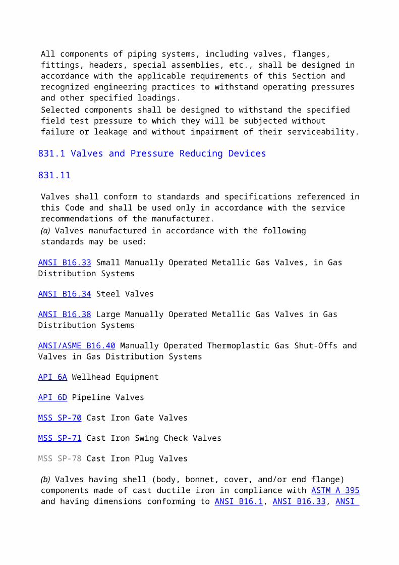
to control fracture propagation when a pipeline is designed to operate either at a hoop stress over 40% through 80% of SMYS in sizes NPS 16 or larger, or at a hoop stress over 72% through 80% of SMYS in sizes smaller than NPS 16.When a fracture toughness criterion is used, control can be achieved by ensuring that the pipe has adequate ductility and either by specifying adequate toughness or installing crack arrestors on the pipeline to stop propagation.(1) Brittle Fracture Control. To ensure that the pipe has adequate ductility, fracture toughness testing shall be performed in accordance with the testing procedures of supplementary requirements SR5 or SR6 of API 5L, or other equivalent alternatives. If the operating temperature is below 32°F, an appropriate lower test temperature shall be used. The appropriate lower test temperature for notch toughness shall be taken to be at or below the lowest expected metal temperature during pressure testing (if with air or gas) and during service, having regard to past recorded temperature data and possible effects of lower air and ground temperatures. The average shear value of the fracture appearance of the test specimens from each heat shall not be less than 35%, and the all-heat average shall not be less than 50% shear when Charpy V-notch testing, based on full-sized Charpy specimens, is specified, or at least 80% of the heats shall exhibit a fracture shear appearance of 40% or more when drop-weight tear testing is specified.(2) Ductile Fracture Arrest. To ensure that the pipeline has adequate toughness to arrest a ductile fracture, the pipe shall be tested in accordance with the procedures of supplementary requirements SR5 of API 5L. The all-heat average of the Charpy energy values shall meet or exceed the energy value calculated using one of the following equations that have been developed in various pipeline research programs.(a) Battelle Columbus Laboratories (BCL) (AGA)
(b) American Iron and Steel Institute (AISI)
(c) British Gas Council (BGC)
(d) British Steel Corporation (BSC)
where
CVN = full-size Charpy V-notch absorbed energy, ft-lb
R = pipe radius, in.
t = wall thickness, in.
= hoop stress, ksi(99) (3) Mechanical Crack Arrestors. Mechanical crack arrestors consisting of sleeves, wire-rope wrap, heavy-wall pipe, or other suitable types have been shown to provide reliable methods of arresting ductile fracture. The mechanical crack arrestors shall be placed at intervals along the pipeline.
CAUTION: The requirements specified in (2) above assume the pipeline is transporting essentially pure methane and the pipe is similar in fracture behavior to that used to develop the empirical equations above. The presence of heavier hydrocarbons can cause the gas to exhibit two-phase behavior on sudden decompression and thus
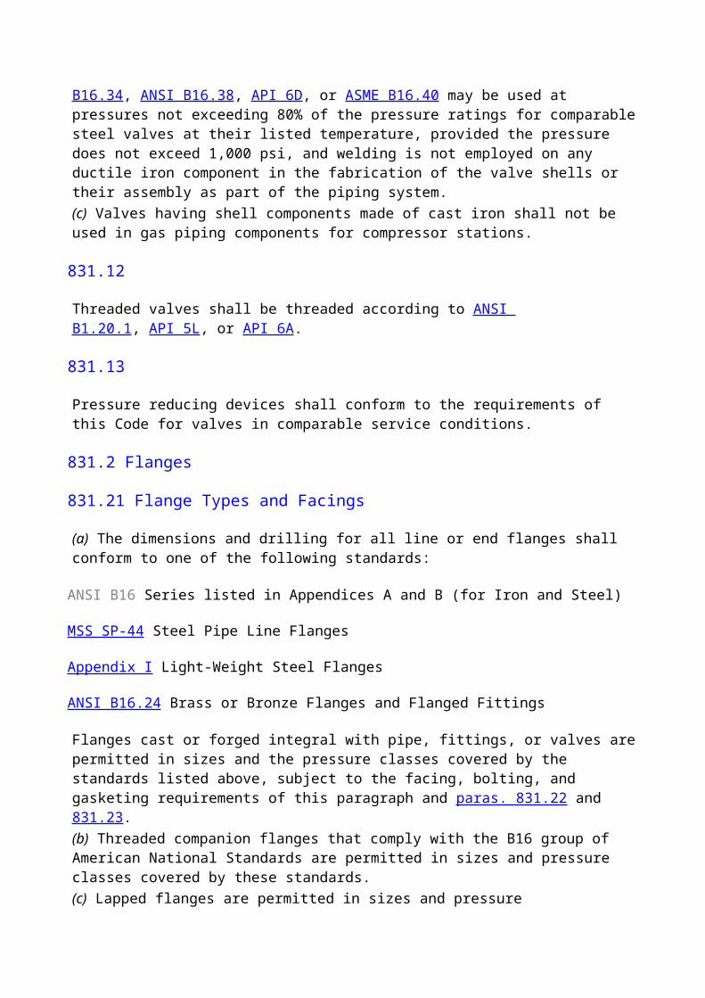
requires a greater Charpy energy to arrest propagating pipe fracture. Likewise, pipe that has been control rolled or quench and tempered may not behave as indicated by the equations and may also require a greater Charpy energy to arrest a propagating fracture. Calculations must be performed to determine if the decompression exhibits two-phase behavior, and an assessment must be made as to the applicability of the arrest equations where additional toughness is may be required. Otherwise, mechanical crack arrestors [see (3) above] should be installed, or the Charpy toughness requirements for arrest should be verified through experiments or additional calculations.
841.111 Limitations on Design Pressure P in Para. 841.11.
The design pressure obtained by the formula in para. 841.11 shall be reduced to conform to the following:(a) P for furnace butt welded pipe shall not exceed the restrictions of para. 841.11 or 60% of mill test pressure, whichever is the lesser.(b) P shall not exceed 85% of the mill test pressure for all other pipes provided; however, that pipe, mill tested to a pressure less than 85% of the pressure required to produce a stress equal to the specified minimum yield, may be retested with a mill type hydrostatic test or tested in place after installation. In the event the pipe is retested to a pressure in excess of the mill test pressure, then P shall not exceed 85% of the retest pressure rather than the initial mill test pressure. It is mandatory to use a liquid as the test medium in all tests in place after installation where the test pressure exceeds the mill test pressure. This paragraph is not to be construed to allow an operating pressure or design pressure in excess of that provided for by para. 841.11.
841.112 Limitations on Specified Minimum Yield Strength S in Para. 841.11
(a) If the pipe under consideration is not new pipe purchased under a specification approved and listed in this Code, the value of S may be determined in accordance with one of the following:(1) S value for new pipe qualified under para. 811.221 or 811.222(2) S value for reuse of steel pipe qualified under one of the provisions of para. 817.1(3) S value for pipe of unknown specification as determined by para. 817.13(h)(b) When pipe that has been cold worked for meeting the specified minimum yield strength is subsequently heated to a temperature higher than 900°F for any period of time or over 600°F for more than 1 hr, the maximum allowable pressure at which it can be used shall not exceed 75% of the value obtained by use of the steel pipe design formula given in para. 841.11.(c) In no case where the Code refers to the specified minimum value of a mechanical property shall the higher actual value of a property be substituted in the steel pipe design formula given in para. 841.11. If the actual value is less than the specified minimum value of a mechanical property, the actual value may be used where it is permitted by the Code, such as in para. 817.1 regarding the reuse of steel pipe.
841.113 Additional Requirements for Nominal Wall Thickness t in Para. 841.11
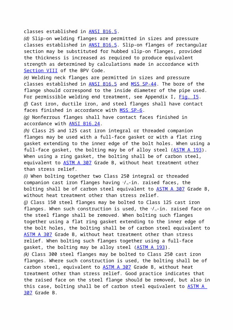
(a) The minimum wall thickness t required for pressure containment as determined by para. 841.11 may not be adequate for other forces to which the pipeline may be subjected. [See para. 840.1(a).] Consideration shall also be given to loading due to transportation or handling of the pipe during construction, weight of water during testing, and soil loading and other secondary loads during operation. Consideration should also be given to welding or mechanical joining requirements. Standard wall thickness, as prescribed in ASME B36.10M, shall be the least nominal wall thickness used for threaded and grooved pipe.(b) Transportation, installation, or repair of pipe shall not reduce the wall thickness at any point to a thickness less than 90% of the nominal wall thickness as determined by para. 841.11 for the design pressure to which the pipe is to be subjected.
841.114 Design Factors F and Location Classes.
The design factor in Table 841.114A shall be used for the designated Location Class. All exceptions to basic design factors to be used in the design formula are given in Table 841.114B.
841.115
The longitudinal joint factor shall be in accordance with Table 841.115A.
841.116
The temperature derating factor shall be in accordance with Table 841.116A.
841.12 Additional Design Information or Instructions
841.121 Fabricated Assemblies.
When fabricated assemblies, such as connections for separators, main line valve assemblies, cross connections, river crossing headers, etc., are to be installed in areas defined in Location Class 1, a design factor of 0.6 is required throughout the assembly and for a distance equal to the lesser of 5 diameters or 10 ft in each direction beyond the last fitting. A shorter distance may be used provided that combined stresses are considered in the design of the installation. Transition pieces at the end of an assembly and elbows used in place of pipe bends are not considered fittings under the requirements of this paragraph. Also see para. 822.
841.122 Pipelines or Mains on Bridges.
The design factor for pipelines or mains supported by rail-road, vehicular, pedestrian, or pipeline bridges shall be determined in accordance with the Location Class prescribed for the area in which the bridge is located. In Location Class 1, however, a design factor of 0.6 shall be used.
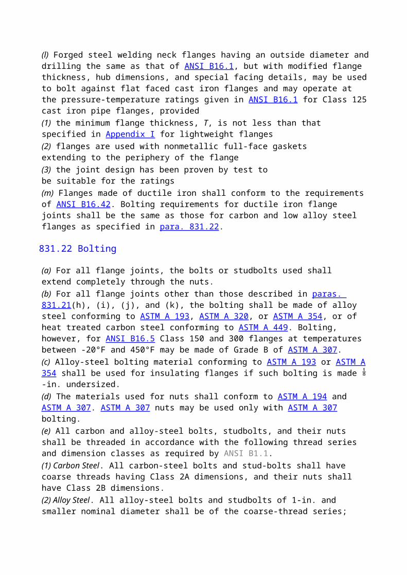
841.13 Protection of Pipelines and Mains From Hazards
(a) When pipelines and mains must be installed where they will be subject to natural hazards, such as washouts, floods, unstable soil, landslides, earthquake-related events (such as surface faulting, soil liquefaction, and soil and slope instability characteristics), or other conditions that may cause serious movement of, or abnormal loads on, the pipeline, reasonable precautions shall be taken to protect the pipeline, such as increasing the wall thickness, constructing revetments, preventing erosion, and installing anchors.(b) Where pipelines and mains cross areas that are normally under water or subject to flooding (i.e., lakes, bays, or swamps), sufficient weight or anchorage shall be applied to the line to prevent flotation.(c) Because submarine crossings may be subject to washouts due to the natural hazards of changes in the waterway bed, water velocities, deepening of the channel, or changing of the channel location in the waterway, design consideration shall be given to protecting the pipeline or main at such crossings. The crossing shall be located in the more stable bank and bed locations. The depth of the line, location of the bends installed in the. banks, wall thickness of the pipe, and weighting of the line shall be selected based on the characteristics of the waterway.(d) Where pipelines and mains are exposed, such as at spans, trestles, and bridge crossings, the pipelines and mains shall be reasonably protected by distance or barricades from accidental damage by vehicular traffic or other causes.
841.14 Cover, Clearance, and Casing Requirements for Buried Steel Pipelines and Mains
841.141 Cover Requirements for Mains.
Buried mains shall be installed with a cover not less than 24 in. Where this cover provision cannot be met, or where external loads may be excessive, the main shall be encased, bridged, or designed to withstand any such anticipated external loads. Where farming or other operations might result in deep plowing, in areas subject to erosion, or in locations where future grading is likely, such as road, highway, railroad, and ditch crossings, additional protection shall be provided.
841.142 Cover Requirements for Pipelines.
Except for offshore pipelines, buried pipelines shall be installed with a cover not less than that shown in the following table:
Cover, in.For Rock
Excavation [Note (1)]Pipe Size Pipe Size
For Normal NPS 20 and Larger Than
Location Excavation Smaller NPS 20Class 1 24 12 18Class 2 30 18 18
Classes 3 and 4 30 24 24
Drainage ditch at public roads and railroad crossings (all locations) 36 24
24NOTE: (1) Rock excavation is excavation that requires blasting.
Where these cover provisions cannot be met or where external loads may be excessive, the pipeline shall be encased, bridged, or designed to withstand any such anticipated external loads. In areas where farming or other operations might result in deep plowing, in areas subject to erosion, or in locations where future grading is likely, such as at roads, highways, railroad crossings, and ditch crossings, additional protection shall be provided.
841.143 Clearance Between Pipelines or Mains and Other Underground Structures
(a) There shall be at least 6 in. of clearance wherever possible between any buried pipeline and any other underground structure not used in conjunction with the pipeline. When such clearance cannot be attained, precautions to protect the pipe shall be taken, such as the installation of casing, bridging, or insulating material.(b) There shall be at least 2 in. of clearance wherever possible between any buried gas main and any other underground structure not used in conjunction with the main. When such clearance cannot be attained, precautions to protect the main shall be taken, such as the installation of insulating material or casing.
841.144 Casing Requirements Under Railroads, Highways, Roads, or Streets.
Casings shall be designed to withstand the superimposed loads. Where there is a possibility of
water entering the casing, the ends of the casing shall be sealed. If the end sealing is of a type that will retain the maximum allowable operating pressure of the carrier pipe, the casing shall be designed for this pressure and at least to the design factor of 0.72. Venting of sealed casings is not mandatory; however, if vents are installed they should be protected from the weather to prevent water from entering the casing. (Requirements for crossings within casing of railroads and highways are shown in Table 841.114B.)
841.15
Design factors are summarized in Table 841.114B.
841.2 Installation of Steel Pipelines and Mains
841.21 Construction Specifications.
All construction work performed on piping systems in accordance with the requirements of this Code shall be done under construction specifications. The construction specifications shall cover all phases of the work and shall be in sufficient detail to cover the requirements of this Code.
841.22 Inspection Provisions
841.221
The operating company shall provide suitable inspection. Inspectors shall be qualified either by experience or training. The inspector shall have the authority to order the repair or removal and replacement of any component found that fails to meet the standards of this Code.
841.222
The installation inspection provisions for pipelines and other facilities to operate at hoop stresses of 20% or more of the specified minimum yield strength shall be adequate to make possible at least the following inspections at sufficiently frequent intervals to ensure good quality of workmanship.(a) Inspect the surface of the pipe for serious surface defects just prior to the coating operation. [See para. 841.242(a).](b) Inspect the surface of the pipe coating as it is lowered into the ditch to find coating lacerations that indicate the pipe might have been damaged after being coated.(c) Inspect the fitup of the joints before the weld is made.(d) Visually inspect the stringer beads before subsequent beads are applied.(e) Inspect the completed welds before they are covered with coating.(f) Inspect the condition of the ditch bottom just before the pipe is lowered in, except for offshore pipelines.(g) Inspect the fit of the pipe to the ditch before backfilling, except for offshore pipelines.(h) Inspect all repairs, replacements, or changes ordered before they are covered.(i) Perform such special tests and inspections as are required by the specifications, such as nondestructive testing of welds and electrical testing of the protective coating.(j) Inspect backfill material prior to use and observe backfill procedure to ensure no damage occurs to the coating in the process of backfilling.
841.23 Bends, Elbows, and Miters in Steel Pipelines and Mains.
Changes in direction may be made by the use of bends, elbows, or miters, under the limitations noted below.
841.231
(a) A bend shall be free from buckling, cracks, or other evidence of mechanical damage.(99) (b) The maximum degree of bending on a field cold bend may be determined by either method in the table below. The first column expresses the maximum deflection in an arc length equal to the nominal outside diameter, and the second column expresses the minimum radius as a function of the nominal outside diameter.
Deflection of Minimum Radius ofNominal Longitudinal Axis, Bend in Pipe DiametersPipe Size deg [see 841.231(c)]
Smaller than 12 841.231(d) 18D12 3.2 18D14 2.7 21D16 2.4 24D18 2.1 27D
20 and larger 1.9 30D(c) A field cold bend may be made to a shorter minimum radius than permitted in (b) above, provided the completed bend meets all other requirements of this section, and the wall thickness after bending is not less than the minimum permitted by para. 841.11. This may be demonstrated through appropriate testing.(d) For pipe smaller than NPS 12, the requirements of (a) above must be met, and the wall thickness after bending shall not be less than the minimum permitted by para. 841.11. This may be demonstrated through appropriate testing.(e) Except for offshore pipelines, when a circumferential weld occurs in a bend section, it shall be subjected to radiography examination after bending.(f) Hot bends made on cold worked or heat treated pipe shall be designed for lower stress levels in accordance with para. 841.112(b).(g) Wrinkle bends shall be permitted only on systems operating at less than 30% of the specified minimum yield strength. When wrinkle bends are made in welded pipe, the longitudinal weld shall be located as near to 90 deg with the top of the wrinkle as conditions will permit. Wrinkle bends with sharp kinks shall not be permitted. Wrinkles shall have a spacing not less than the distance equal to the diameter of the pipe measured along the crotch. On pipe NPS 16 and larger, the wrinkle shall not produce an angle of more than 1 deg per wrinkle.
841.232
Mitered bends are permitted provided the following limitations are met:(a) In systems intended to operate at 40% or more of the specified minimum yield strength, mitered bends are not permitted. Deflections caused by misalignment up to 3 deg are not considered as miters.(b) In systems intended to operate at 10% or more but less than 40% of the specified minimum yield strength, the total deflection angle at each miter shall not exceed 12 deg.(c) In systems intended to operate at less than 10% of the specified minimum yield strength, the total deflection angle at each miter shall not exceed 90 deg.(d) In systems intended to operate at 10% or more of the specified minimum yield strength, the minimum distance between miters measured at the crotch shall not be less than one pipe diameter.(e) Care shall be taken in making mitered joints to provide proper spacing and alignment and full penetration.
841.233
Factory-made, wrought-steel welding elbows or transverse segments cut therefrom may be used for changes in direction, provided that the arc length measured along the crotch is at least 1 in. on pipe sizes NPS 2 and larger.
841.24 Pipe Surface Requirements Applicable to Pipelines and Mains to Operate at a Hoop Stress of 20% or More of the Specified Minimum Yield Strength.
Gouges, grooves, and notches have been found to be an important cause of pipeline failures, and all harmful defects of this nature must be prevented, eliminated, or repaired. Precautions shall be taken during manufacture, hauling, and installation to prevent the gouging or grooving of pipe.
841.241 Detection of Gouges and Grooves
(a) The field inspection provided on each job shall be suitable to reduce to an acceptable minimum the chances that gouged or grooved pipe will get into the finished pipeline or main. Inspection for this purpose just ahead of the coating operation and during the lowering-in and backfill operation is required.(b) When pipe is coated, inspection shall be made to determine that the coating machine does not cause harmful gouges or grooves.(c) Lacerations of the protective coating shall be carefully examined prior to the repair of the coating to determine if the pipe surface has been damaged.
841.242 Field Repair of Gouges and Grooves
(a) Injurious gouges or grooves shall be removed.(b) Gouges or grooves may be removed by grinding to a smooth contour, provided that the resulting wall thickness is not less than the minimum prescribed by this Code for the conditions of usage. [See para. 841.113(b).](c) When the conditions outlined in para. 841.242(b) cannot be met, the damaged portion of pipe shall be cut out as a cylinder and replaced with a good piece. Insert patching is prohibited.
841.243 Dents
(a) A dent may be defined as a depression that produces a gross disturbance in the curvature of the pipe wall (as opposed to a scratch or gouge, which reduces the pipe wall thickness). The depth of a dent shall be measured as the gap between the lowest point of the dent and a prolongation of the original contour of the pipe in any direction.(b) A dent, as defined in para. 841.243(a), which contains a stress concentrator such as a scratch, gouge, groove, or arc bum shall be removed by cutting out the damaged portion of the pipe as a cylinder.(c) All dents that affect the curvature of the pipe at the longitudinal weld or any circumferential weld shall be removed. All dents that exceed a maximum depth of in. in pipe NPS 12 and smaller or 2% of the nominal pipe diameter in all pipe greater than NPS 12 shall not be permitted in pipelines or mains intended to operate at 40% or more of the specified minimum yield strength. When dents are removed, the damaged portion of the pipe shall be cut out as a cylinder. Insert patching and pounding out of the dents is prohibited.
(99)841.244Notches
(a) Notches on the pipe surface can be caused by mechanical damage in manufacture, transportation, handling, or installation, and when determined to be mechanically caused, shall be treated the same as gouges and grooves in para. 841.241.(b) Stress concentrations that may or may not involve also be created by a process involving thermal energy in which the pipe surface is heated sufficiently to change its mechanical or metallurgical properties. These imperfections are termed "metallurgical notches." Examples include an arc bum produced by accidental contact with a welding electrode or a grinding bum produced by excessive force on a grinding wheel. Metallurgical notches may result in even more severe stress concentrations than a mechanical notch and shall be prevented or eliminated in all pipelines intended to operate at 20% or more of the specified minimum yield strength.
841.245 Elimination of Are Burns.
The metallurgical notch caused by arc bums shall be removed by grinding, provided the grinding does not reduce the remaining wall thickness to less than the minimum prescribed by this Code for the conditions of use.5 In all other cases, repair is prohibited, and the portion of pipe containing the arc bum must be cut out as a cylinder and replaced with a good piece. Insert patching is prohibited. Care shall be exercised to ensure that the heat of grinding does not produce a metallurgical notch.
841.25 Miscellaneous Operations Involved in the Installation of Steel Pipelines and Mains
841.251 Handling, Hauling, and Stringing.
Care shall be taken in the selection of the handling equipment and in handling, hauling, unloading, and placing the pipe so as not to damage the pipe.
841.252 Installation of Pipe in the Ditch.
On pipelines operating at stresses of 20% or more of the specified minimum yield strength, it is important that stresses imposed on the pipeline by construction be minimized. Except for offshore pipelines, the pipe shall fit the ditch without the use of external force to hold it in place until the backfill is completed. When long sections of pipe that have been welded alongside the ditch are lowered in, care shall be exercised so as not to jerk the pipe or impose any strains that may kink or put a permanent bend in the pipe. Slack loops are not prohibited by this paragraph where laying conditions render their use advisable.
841.253 Backfilling
(a) Backfilling shall be performed in a manner to provide firm support under the pipe.(b) If there are large rocks in the material to be used for backfill, care shall be used to prevent damage to the coating by such means as the use of rock shield material, or by making the initial fill with rock-free material sufficient to prevent damage.(c) Where the trench is flooded to consolidate the backfill, care shall be exercised to see that the pipe is not floated from its firm bearing on the trench bottom.
841.26 Hot Taps.
All hot taps shall be installed by trained and experienced crews.
841.27 Precautions to Avoid Explosions of Gas-Air Mixtures or Uncontrolled Fires During Construction Operations
841.271
Operations such as gas or electric welding and cutting with cutting torches can be safely performed on pipelines, mains, and auxiliary equipment, provided that they are completely full of gas or of air that is free from combustible material. Steps shall be taken to prevent a mixture of gas and air at all points where such operations are to be performed.
841.272
When a pipeline or main can be kept full of gas during a welding or cutting operation, the following procedures are recommended:(a) Keep a slight flow of gas moving toward the point where cutting or welding is being done.(99) (b) Control the gas pressure at the site of the work by a suitable means.(c) After a cut is made, immediately close all slots or open ends with tape, tightly fitted canvas, or other suitable materials.(d) Do not permit two openings to remain uncovered at the same time. This is doubly important if the two openings are at different elevations.
841.273
Welding, cutting, or other operations that could be a source of ignition shall not be done on a pipeline, main, or auxiliary apparatus that contains air, if it is connected to a source of gas, unless a suitable means has been provided to prevent the formation of an explosive mixture in the work area.
841.274
In situations where welding or cutting must be done on facilities that are filled with air and connected to a source of gas, and the precautions recommended above cannot be taken, one or more of the following precautions, depending on circumstances at the jobsite, are suggested:(a) purging of the pipe or equipment upon which welding or cutting is to be done with an inert gas or continuous purging with air in such a manner that a combustible mixture does not form in the facility at the work area(b) testing of the atmosphere in the vicinity of the zone to be heated before the work is started and at intervals as the work progresses with a combustible gas indicator or by other suitable means(c) careful verification before and during the work ensuring that the valves that isolate the work from a source of gas do not leak.
841.275 Purging of Pipelines and Mains
(a) When a pipeline or main is to be placed in service, the air in it shall be displaced. The following are some acceptable methods:(1) Introduce a moderately rapid and continuous flow of gas into one end of the line and vent the air out the other end. The gas flow shall be continued without interruption until the vented gas is free of air.(2) If the vent is in a location where the release of gas into the atmosphere may cause a hazardous condition, then a slug of inert gas shall be introduced between the gas and air. The gas flow shall then be continued without interruption until all of the air and inert gas have been removed from the facility. The vented gases shall be monitored and the vent shall be closed before any substantial quantity of combustible gas is released to the atmosphere.(b) In cases where gas in a pipeline or main is to be displaced with air and the rate at which air can be supplied to the line is too small to make a procedure similar to but the reverse of that described in (a) above feasible, a slug of inert gas should be introduced to prevent the formation of an explosive mixture at the interface between gas and air. Nitrogen or carbon dioxide can be used for this purpose.
(c) If a pipeline or main containing gas is to be removed, the operation may be carried out in accordance with para. 841.272, or the line may be first disconnected from all sources of gas and then thoroughly purged with air, water, or inert gas before any further cutting or welding is done.(d) If a gas pipeline, main, or auxiliary equipment is to be filled with air after having been in service and there is a reasonable possibility that the inside surfaces of the facility are wetted with volatile inflammable liquid, or if such liquids might have accumulated in low places, purging procedures designed to meet this situation shall be used. Steaming of the facility until all combustible liquids have been evaporated and swept out is recommended. Filling of the facility with an inert gas and keeping it full of such gas during the progress of any work that might ignite an explosive mixture in the facility is an alternative recommendation. The possibility of striking static sparks within the facility must not be overlooked as a possible source of ignition.
841.276
Whenever the accidental ignition in the open air of gas-air mixture might be likely to cause personal injury or property damage, precautions shall be taken. For example:(a) Prohibit smoking and open flames in the area.(b) Install a metallic bond around the location of cuts in gas pipes to be made by means other than cutting torches.(c) Take precautions to prevent static electricity sparks.(d) Provide a fire extinguisher of appropriate size and type, in accordance with ANSI/NFPA 10.
841.3 Testing After Construction
841.31 General Provisions.
All piping systems shall be tested after construction to the requirements of this Code except for pretested fabricated assemblies, pretested tie-in sections, and tie-in connections.The circumferential welds of welded tie-in connections not pressure tested after construction shall be inspected by radiographic or other accepted nondestructive methods in accordance with para. 826.2.Nonwelded tie-in connections not pressure tested after construction shall be leak tested at not less than the pressure available when the tie-in is placed into service.
841.32 Test Required to Prove Strength of Pipelines and Mains to Operate at Hoop Stresses of 30% or More of the Specified Minimum Yield Strength of the Pipe
841.321
All pipelines and mains to be operated at a hoop stress of 30% or more of the specified minimum yield strength of the pipe shall be given a test for at least 2 hr to prove strength after construction and before being placed in operation.
841.322 Location Classes 1-4
(a) Pipelines located in Location Class 1, Division 1 shall be tested hydrostatically to 1.25 times
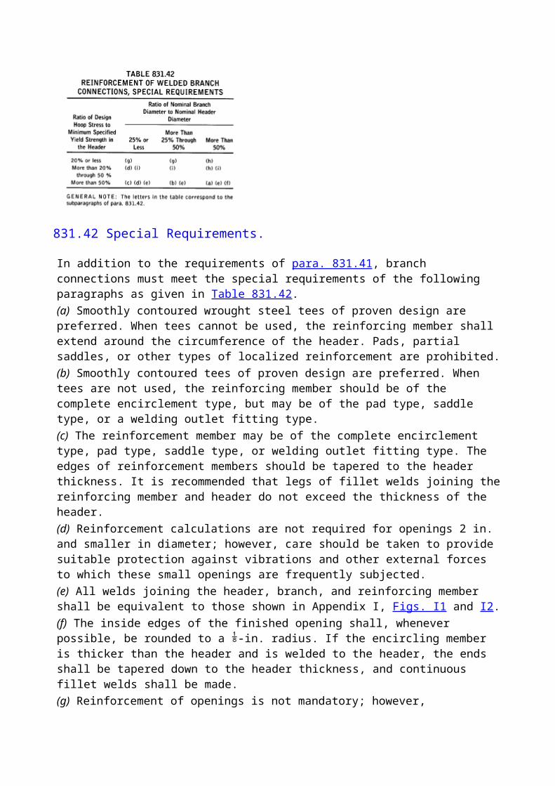
design pressure if the maximum operating pressure is greater than 72% SMYS. (See para. 841.36.)(b) Pipelines located in Location Class 1, Division 2 shall be tested either with air or gas to 1.1 times the maximum operating pressure or hydrostatically to at least 1.1 times the maximum operating pressure if the maximum operating pressure is 72% SMYS or less. (See para. 841.36.)(c) Pipelines and mains in Location Class 2 shall be tested either with air to 1.25 times the maximum operating pressure or hydrostatically to at least 1.25 times the maximum operating pressure. (See para. 841.36.)(d) Pipelines and mains in Location Classes 3 and 4 shall be tested hydrostatically to a pressure not less than 1.4 times the maximum operating pressure. This requirement does not apply if, at the time the pipeline or main is first ready for test, one or both of the following conditions exist:(1) The ground temperature at pipe depth is 32°F or less, or might fall to that temperature before the hydrostatic test could be completed, or(2) Water of satisfactory quality is not available in sufficient quantity.In such cases an air test to 1.1 times the maximum operating pressure shall be made, and the limitations on operating pressure imposed by Table 841.322(f) do not apply.(e) The test requirement given in paras. 841.322(a), (b), (c), and (d) are summarized in Table 841.322(f). (See also para. 816.)(f) In selecting the test level, the designer or operating company should be aware of the provisions of para. 854 and the relationship between test pressure and operating pressure when the pipeline experiences a future increase in the number of dwellings intended for human occupancy.
841.323
Other provisions of this Code notwithstanding, pipelines and mains crossing highways and railroads may be tested in each case in the same manner and to the same pressure as the pipeline on each side of the crossing.
841.324
Other provisions of this Code notwithstanding, fabricated assemblies, including main line valve assemblies, cross connections, river crossing headers, etc., installed in pipelines in Location Class 1 and designed in accordance with a design factor of 0.60 as required in para. 841.121, may be tested as required for Location Class 1.
841.325
Notwithstanding the limitations on air testing imposed on para. 841.322(d), air testing may be used in Location Classes 3 and 4, provided that all of the following conditions apply:(a) The maximum hoop stress during the test is less than 50% of the specified minimum yield strength in Location Class 3, and less than 40% of the specified minimum yield strength in Location Class 4.(b) The maximum pressure at which the pipeline or main is to be operated does not exceed 80% of the maximum field test pressure used.(c) The pipe involved is new pipe having a longitudinal joint factor, E, in Table 841.115A of 1.00.
841.326 Records.
The operating company shall maintain in its file for the useful life of each pipeline and main,
records showing the procedures used and the data developed in establishing its maximum allowable operating pressure.
841.33 Tests Required to Prove Strength for Pipelines and Mains to Operate at Less Than 30% of the Specified Minimum Yield Strength of the Pipe, but in Excess of 100 psi.
Steel piping that is to operate at stresses less than 30% of the specified minimum yield strength in Class 1 Locations shall at least be tested in accordance with para. 841.34. In Class 2, 3, and 4 Locations, such piping shall be tested in accordance with Table 841.322(f), except that gas or air may be used as the test medium within the maximum limits set in Table 841.33.
841.34 Leak Tests for Pipelines or Mains to Operate at 100 psi or More
841.341
Each pipeline and main shall be tested after construction and before being placed in operation to demonstrate that it does not leak. If the test indicates that a leak exists, the leak or leaks shall be located and eliminated, unless it can be determined that no undue hazard to public safety exists.
841.342
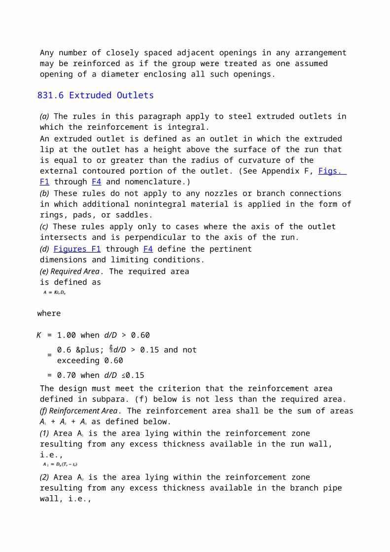
The test procedure used shall be capable of disclosing all leaks in the section being tested and shall be selected after giving due consideration to the volumetric content of the section and to its location. This requires the exercise of responsible and experienced judgement, rather than numerical precision.
841.343
In all cases where a line is to be stressed in a strength proof test to 20% or more of the specified minimum yield strength of the pipe, and gas or air is the test medium, a leak test shall be made at a pressure in the range from 100 psi to that required to produce a hoop stress of 20% of the minimum specified yield, or the line shall be walked while the hoop stress is held at approximately 20% of the specified minimum yield.
841.35 Leak Tests for Pipelines and Mains Operate at Less Than 100 psi
841.351
Each pipeline, main, and related equipment that will operate at less than 100 psi shall be tested after construction and before being placed in operation to demonstrate that it does not leak.
841.352
Gas may be used as the test medium at the maximum pressure available in the distribution system at the time of the test. In this case, the soap bubble test may be used to locate leaks if all joints are accessible during the test.
841.353
Testing at available distribution system pressures as provided for in para. 841.352 may not be adequate if substantial protective coatings are used that would seal a split pipe seam. If such coatings are used, the leak test pressure shall be 100 psi.
841.36 Safety During Tests.
All testing of pipelines and mains after construction shall be done with due regard for the safety of employees and the public during the test. When air or gas is used, suitable steps shall be taken to keep persons not working on the testing operations out of the testing area when the hoop stress is first raised from 50% of the specified minimum yield to the maximum test stress, and until the pressure is reduced to the maximum operating pressure.
(99)841.4 Commissioning of Facilities
841.41 General.
Written procedures shall be established for commissioning. Procedures shall consider the characteristics of the gas to be transported, the need to isolate the pipeline from other connected facilities, and the transfer of the constructed pipeline to those responsible for its operation.
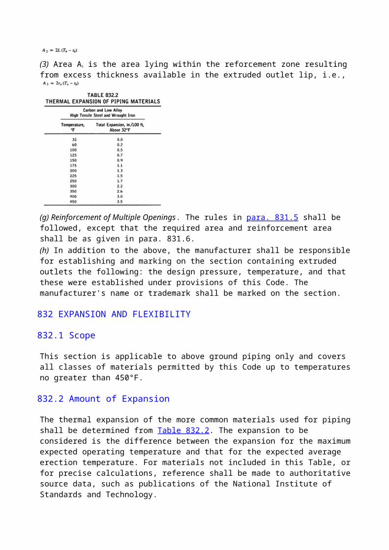
Commissioning procedures, devices, and fluids shall be selected to ensure that nothing is introduced into the pipeline system that will be incompatible with the gas to be transported, or with the materials in the pipeline components.
841.42 Cleaning and Drying Procedures.
Consideration shall be given to the need for cleaning and drying the pipe and its components beyond that required for removal of the test medium.
841.43 Functional Testing of Equipment and Systems.
As a part of commissioning, all pipeline and compressor station monitor and control equipment and systems shall be fully function-tested, especially including safety systems such as pig trap interlocks, pressure and flow-monitoring systems, and emergency pipeline shut-down systems. Consideration should also be given to performing a final test of pipeline valves before the gas is introduced to ensure that each valve is operating correctly.
841.44 Start-Up Procedures and Introduction of Transported Gas.
Written start-up procedures shall be prepared before introducing the transported gas into the system and shall require the following:(a) the system be mechanically complete and operational(b) all functional tests be performed and accepted(c) all necessary safety systems be operational(d) operating procedures be available(e) a communications system be established(f) transfer of the completed pipeline system to those responsible for its operation
841.45 Documentation and Records.
The following commissioning records shall be maintained as permanent records:(a) cleaning and drying procedures(b) cleaning and drying results(c) function-testing records of pipeline monitoring(d) control equipment systems(e) completed prestart checklist
842 OTHER MATERIALS
842.2 Ductile Iron Piping Systems Requirements
842.21 Ductile Iron Pipe Design
842.211 Determination of Required Wall Thickness.
Ductile iron pipe shall be designed in accordance with the methods set forth in ANSI/AWWA C150/A21.50.
842.212 Allowable Values of s and f.
The values of design hoop stress s and design bending stress f at the bottom of the pipe, to be used in the equations given in ANSI/AWWA C150/A21.50, are s = 16,800 psi
f = 36,000 psi
842.213 Standard Ductile Iron Strength and Conformance to ANSI A21.5.2.
Ductile iron pipe shall be (60-42-10) grade and shall conform to all requirements of ANSI A21.5.2. Grade (60-42-10) ductile iron has the following mechanical properties: Minimum tensile strength 60,000 psiMinimum yield strength 42,000 psiMinimum elongation 10%
842.214 Allowable Thickness for Ductile Iron Pipe.
The least ductile iron pipe thickness permitted are the lightest standard class for each nominal pipe size as shown in ANSI A21.52. Standard wall thicknesses for 250 psi maximum working pressure and standard laying conditions at several depths of cover are shown in Table 842.214.
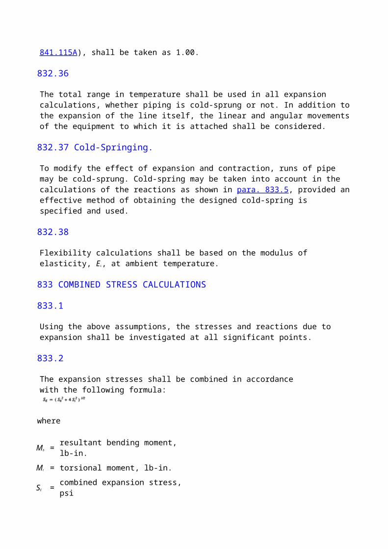
842.215 Ductile Iron Pipe Joints
(a) Mechanical Joints. Ductile iron pipe with mechanical joints shall conform to the requirements of ANSI A21.5.2 and ANSI/AWWA C111/A21.11. Mechanical joints shall be assembled in accordance with "Notes on Installation of Mechanical Joints" in ANSI/AWWA C111/A21.11.(b) Other Joints. Ductile iron pipe may be furnished with other types of joints provided they are properly qualified and meet the appropriate provisions of this Code. Such joints shall be assembled in accordance with applicable standards or in accordance with the manufacturer's written recommendations.(c) Threaded Joints. The use of threaded joints to couple lengths of ductile iron pipe is not recommended.
842.22 Installation of Ductile Iron Pipe
842.221 Laying.
Ductile iron pipe shall be laid in accordance with the applicable field conditions described in ANSI/AWWA C150/A21.50.
842.222
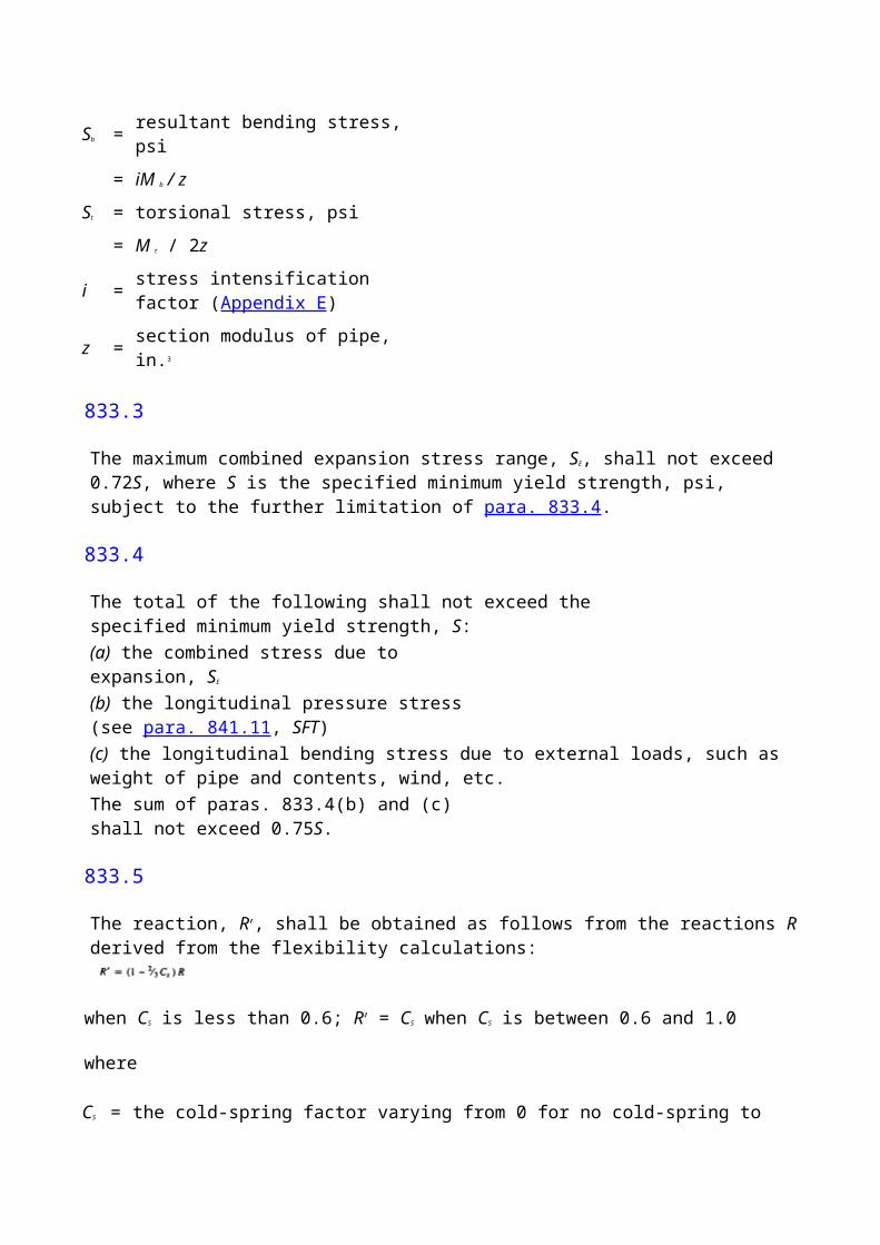
Underground ductile iron pipe shall be installed with a minimum cover of 24 in. unless prevented by other underground structures. Where sufficient cover cannot be provided to protect the pipe from external loads or damage and the pipe is not designed to withstand such external loads, the pipe shall be cased or bridged to protect the pipe.
842.223 Joint Restraint.
Suitable harnessing or buttressing shall be provided at points where the main deviates from a straight line and the thrust, if not restrained, would separate the joints.
842.224 Making Ductile Iron Field Joints.
Ductile iron pipe joints shall conform to para. 842.215 and shall be assembled according to recognized American National Standards or in accordance with the manufacturer's written recommendations.
842.23 Testing Ductile Iron Field Joints.
Ductile iron pipe joints shall be leak tested in accordance with para. 841.34 or 841.35.
842.3 Design of Plastic Piping
General Provisions. The design requirements of this section are intended to limit the use of plastic piping primarily to mains and service lines in typical distribution systems operating at a pressure of 100 psi or less. For other applications in Class 1 or 2 locations, plastic piping may be used within the limitations prescribed in this Code.
842.31 Plastic Pipe and Tubing Design Formula.
The design pressure for plastic gas piping systems or the nominal wall thickness for a given design pressure (subject to the limitations in para. 842.32) shall be determined by the following formula:
where
D = specified outside diameter, in
P = design pressure, psig
S = for thermoplastic pipe and tubing, long-term hydrostatic strength determined in accordance with the listed specification at a temperature equal to 73°F, 100°F, 120°F, or 140°F; for reinforced thermosetting plastic pipe, use 11,000 psi
t = specified wall thickness, in.
NOTE: Long-term hydrostatic strength at 73°F for the plastic materials whose specifications are incorporated by reference herein are given in Appendix D.
842.32 Thermoplastic Design Limitations
(a) The design pressure shall not exceed 100 psig.(b) Thermoplastic pipe, tubing, and fittings shall not be used where the operating temperatures of the materials will be(1) below -20°F; or(2) above the temperature at which the long-term hydrostatic strength used in the design formula in para. 842.31 is determined, except that in no case shall the temperature exceed 140°F.(c) The value of t for thermoplastic pipe shall not be less than that shown in Table 842.32(c).(d) The value of t for thermoplastic tubing shall not be less than 0.062 in.(e) For saddle type service connections made by heat fusion techniques, it may be necessary for some materials, which are intended for use at high operating pressures, to require a heavier wall thickness than defined by the pressure design formula for sizes 2 in. and smaller. Manufacturers of the specific pipe material should be contacted for recommendations or a qualified procedure shall be used.
842.33 Reinforced Thermosetting Plastic Design Limitations
(a) The value of P for reinforced thermosetting plastic mains and service lines in distribution systems in all class locations and for other applications in Class 3 and 4 locations shall not exceed 100 psig.(b) Reinforced thermosetting plastic pipe and fittings shall not be used where operating temperatures will be below -20°F or above 150°F.(c) The value of t for reinforced thermosetting plastic pipe shall not be less than that shown in Table 842.33(c).
842.34 Design Pressure of Plastic Fittings.
The maximum pressure rating for fittings shall be the same value as the maximum design pressure of the corresponding pipe size and wall thickness as indicated in the referenced standard for the fittings and as determined in paras. 842.31 and 842.32. The manufacturer should be consulted for advice on maximum pressure ratings for fittings not covered by referenced standards.
842.35 Valves in Plastic Piping
842.351
Valves in plastic piping may be made of any suitable material and design permitted by this Code.
842.352
Valve installations in plastic piping shall be so designed as to protect the plastic material against excessive torsional or shearing loads when the valve or shutoff is operated, and from any other secondary stresses that might be exerted through the valve or its enclosure.
842.36 Protection From Hazards.
Plastic piping shall conform to the applicable provisions of para. 841.13.
842.37 Cover and Casing Requirements Under Railroads, Roads, Streets, or Highways.
Plastic piping shall conform to the applicable requirements of paras. 841.141 and 841.144. Where plastic piping must be cased or bridged, suitable precautions shall be taken to prevent crushing or shearing of the piping. (See also para. 842.43.)
842.38 Clearance Between Mains and Other Underground Structures.
Plastic piping shall conform to the applicable provisions of para. 841.143. Sufficient clearance shall be maintained between plastic piping and steam, hot water, or power lines and other sources of heat to prevent operating temperatures in excess of the limitations of para. 842.32(b) or 842.33(b).
842.39 Plastic Pipe and Tubing Joints and Connections
842.391 General Provisions.
Plastic pipe, tubing, and fittings may be joined by the solvent cement method, adhesive method, heat-fusion method, or by means of compression couplings or flanges. The method used must be compatible with the materials being joined. The recommendations of the manufacturer shall be considered when determining the method to be used.
842.392 Joint Requirements
(a) Pipe or tubing shall not be threaded.(b) Solvent cement joints, adhesive joints, and heat-fusion joints shall be made in accordance with qualified procedures that have been established and proven by test to produce gas-tight joints at least as strong as the pipe or tubing being joined.(c) Joints shall be made by personnel qualified by training or experience in the proper procedures required for the type of joint involved.(d) Solvent cement or heat-fusion joints shall be used only when joining components made of the same thermoplastic materials.(e) Heat-fusion or mechanical joints shall be used when joining polyethylene pipe, tubing, or fittings. Polyethylene components made of different grades of materials may be heat-fused provided that properly qualified procedures for joining the specific components are used. Any combination of PE 2306, PE 3306, and PE 3406 materials may be joined by heat fusion.(f) Flanges or special joints may be used provided they are properly qualified and used in accordance with the appropriate provisions of this Code.
842.393 Solvent Cement Joints
(a) Square cut ends free of burrs are required for a proper socket joint.(b) Proper fit between the pipe or tubing and mating socket or sleeve is essential to a good joint. Sound joints cannot normally be made between loose or very tight fitting components.(c) The mating surfaces must be clean, dry, and free of material that might be deterimental to the joint.(d) Solvent cements that conform to ASTM D 2513 and are recommended by the pipe or tubing manufacturer shall be used to make cemented joints.(e) A uniform coating of the solvent cement is required on both mating surfaces. After the joint is made, excess cement shall be removed from the outside of the joint. The joint shall not be disturbed until it has properly set.(f) The solvent cement and piping components to be joined may be conditioned prior to assembly by warming if done in accordance with the manufacturer's recommendations.(g) A solvent cement joint shall not be heated to accelerate the setting of the cement.(h) Safety requirements in Appendix A of ASTM D 2513 shall be followed when solvent cements are used.
842.394 Heat-Fusion Joints
(a) Sound butt heat-fusion joints require the use of a jointing device that holds the heater element
square to the ends of the piping, can compress the heated ends together, and holds the piping in proper alignment while the plastic hardens.(b) Sound socket heat-fusion joints require the use of a jointing device that heats the mating surfaces of the joint uniformly and simultaneously to essentially the same temperature. The completed joint must not be disturbed until properly set.(c) Care must be used in the heating operation to prevent damage to the plastic material from overheating or having the material not sufficiently heated to ensure a sound joint. Direct application of heat with a torch or other open flame is prohibited.(d) When connecting saddle-type fittings to pipe NPS 2 and smaller, see para. 842.32(e) to minimize the possibility of failures.
842.395 Adhesive Joints
(a) Adhesives that conform to ASTM D 2517 and are recommended by the pipe, tubing, or fitting manufacturer shall be used to make adhesive bonded joints.(b) When dissimilar materials are bonded together, a through investigation shall be made to determine that the materials and adhesive used are compatible with each other.(c) An adhesive bonded joint may be heated in accordance with the pipe manufacturer's recommendation to accelerate cure.(d) Provisions shall be made to clamp or otherwise prevent the joined materials from moving until the adhesive is properly set.
(99)842.396 Mechanical Joints6
(a) When compression-type mechanical joints are used, the elastomeric gasket material in the fitting shall be compatible with the plastic (i.e., the plastic and the elastomer shall not cause deterioration in one another's chemical and physical properties over a long period).(b) The tubular stiffener required to reinforce the end of the pipe or tubing shall extend at least under that section of the pipe being compressed by the gasket or gripping material. The stiffener shall be free of rough or sharp edges and shall not be a force fit in the pipe or tube. Split tubular fittings shall not be used.(c) Since pull-out resistance of compression-type fittings varies with type and size, all mechanical joints shall be designed and installed to effectively sustain the longitudinal, pull-out forces caused by contraction of the piping or by maximum anticipated external loading. The installation shall be designed and made to minimize these forces as follows:(1) In the case of direct burial when the pipe is sufficiently flexible, the pipe may be snaked in the ditch.(2) In the case of pipe installed by insertion in casing, the pipe shall be pushed rather than pulled into place so as to place it in compression rather than tension.(3) Allowance shall be made for thermal expansion and contraction due to seasonal changes in temperature of installed pipe. The importance of this allowance increases as the length of the installation increases. Such allowance is of paramount importance when the plastic pipe is used for insertion renewal inside another pipe, because it is not restrained by earth loading. This allowance may be accomplished by appropriate combinations of(a) offsets(b) anchoring(c) aligning the pipe and fitting(d) in the case of compression, fittings by the use of long-style types and placement of the pipe in
slight axial compression(e) expansion-contraction devices, or(f) fittings designed to prevent pull-outTypical coefficients of thermal expansion, which may be used to make calculations, are given in Table 842.396(c).
842.4 Installation of Plastic Piping
842.41 Construction Specifications.
All construction work performed on piping systems in accordance with the requirements of this Code shall be done using construction specifications. The construction specifications shall cover the requirements of this Code and shall be in sufficient detail to ensure proper installation.
842.42 Inspection and Handling Provisions.
Plastic piping components are susceptible to damage by mishandling. Gouges, cuts, kinks, or other forms of damage may cause failure. Care shall be exercised during handling and installation to prevent such damage.
842.421
Plastic pipe and tubing shall be carefully inspected for cuts, scratches, gouges, and other imperfections before use, and any pipe or tubing containing harmful imperfections shall be rejected.
842.422
Each installation shall be field inspected to detect harmful imperfections. Any such imperfections found shall be eliminated.
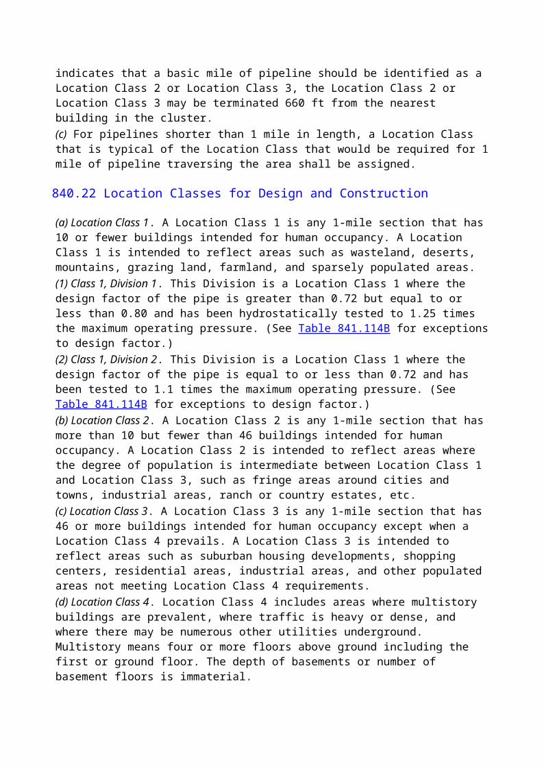
842.423
Skillful application of qualified techniques and the use of proper materials and equipment in good condition are required to achieve sound joints in plastic piping by the solvent cement, adhesive, or heat fusion methods. Inspection provisions shall be checked visually. If there is any reason to believe the joint is defective, it shall be removed and replaced.
842.424
Care shall be exercised to avoid rough handling of plastic pipe and tubing. It shall not be pushed or pulled over sharp projections or dropped, or it shall not have other objects dropped on it. Care shall be taken to prevent kinking or buckling, and any kinks or buckles that occur shall be removed by cutting out as a cylinder.
842.425
Care shall be exercised at all times to protect the plastic material from fire, excessive heat, or harmful chemicals.
842.426
Plastic pipe and tubing shall be adequately supported during storage. Thermoplastic pipe, tubing, and fittings shall be protected from long-term exposure to direct sunlight.
842.43 Installation Provisions
(a) Plastic piping may be installed above ground only if it is (1) encased in metal pipe that is protected against atmospheric corrosion; protected against deterioration (e.g., high-temperature degradation); and protected against external damage; or(2) installed for plastic service lines as permitted in para. 849.52(b)Plastic pipe shall not be used to support external loads. Encased plastic pipe shall be able to withstand anticipated temperatures without deteriorating or decreasing in strength below the design limitations stated in paras. 842.32 and 842.33. When protecting against external damage, consideration shall be given to the need to isolate the encased segment and to safely vent or contain gas that may escape the plastic pipe in the event of a leak or rupture.(b) Plastic piping shall not be installed in vaults or any other below-grade enclosure unless it is completely encased in gas-tight metal pipe and metal fittings having adequate corrosion protection.(c) Plastic piping shall be installed in such a way that shear or tensile stresses resulting from construction, backfill, thermal contraction, or external loading are minimized. (See para. 842.396.)
842.431 Direct Burial
(a) Directly buried thermoplastic pipe or tubing shall have a minimum wall thickness of 0.090 in. in all sizes except NPS pipe and in. and smaller nominal diameter tubing, which shall have a minimum wall thickness of 0.062 in.(b) Plastic piping shall be laid on undisturbed or well-compacted soil. If plastic piping is to be laid in soils that may damage it, the piping shall be protected by suitable rock-free materials before backfilling is completed. Plastic piping shall not be supported by blocking. Well-tamped earth or
other continuous support shall be used.(c) The piping shall be installed with sufficient slack to provide for possible contraction. Cooling may be necessary before the last connection is made under extremely high temperature conditions. (See para. 842.396.)(d) When long sections of piping that have been assembled alongside the ditch are lowered in, care shall be exercised to avoid any strains that may overstress or buckle the piping or impose excessive stress on the joints.(e) Backfilling shall be performed in a manner to provide firm support around the piping. The material used for backfilling shall be free of large rocks, pieces of pavement, or any other materials that might damage the pipe.(f) Where flooding of the trench is done to consolidate the backfill, care shall be exercised to see that the piping is not floated from its firm bearing on the trench bottom.(g) An electrically conductive wire should be installed with the piping to facilitate locating it with an electronic pipe locator. Other suitable material may be employed.
842.432 Insertion of Casing
(a) The casing pipe shall be prepared to the extent necessary to remove any sharp edges, projections, or abrasive material that could damage the plastic during and after insertion.(b) Plastic pipe or tubing shall be inserted into the casing pipe in such a manner so as to protect the plastic during the installation. The leading end of the plastic shall be closed before insertion. Care shall be taken to prevent the plastic piping from bearing on the end of the casing.(c) The portion of the plastic piping exposed due to the removal of a section of the casing pipe shall be of sufficient strength to withstand the anticipated external loading, or it shall be protected with a suitable bridging piece capable of withstanding the anticipated external loading.(d) The portion of the plastic piping that spans disturbed earth shall be adequately protected by a bridging piece or other means from crushing or shearing from external loading or settling of backfill.(e) The piping shall be installed to provide for possible contraction. Cooling may be necessary before the last connection is made when the pipe has been installed in hot or warm weather. (See para. 842.396.)(f) If water accumulates between the casing and the carrier pipe where it may be subjected to freezing temperatures, the carrier pipe can be constricted to the point where the capacity is affected or the pipe wall could be crushed and leak. To avoid this, one or more of the following steps shall be taken:(1) The annulus between the carrier pipe and casing shall be kept to a minimum so that the increased volume of water changing to ice will be insufficient to crush the carrier pipe.(99) (2) Adequate draining for the casing shall be provided.(99) (3) Filler such as foam shall be inserted into the annulus between the casing and the carrier pipe.
842.44 Bends and Branches.
Changes in direction of plastic piping may be made with bends, tees, or elbows under the following limitations:(a) Plastic pipe and tubing may be deflected to a radius not less than the minimum recommended by the manufacturer for the kind, type, grade, wall thickness, and diameter of the particular plastic used.
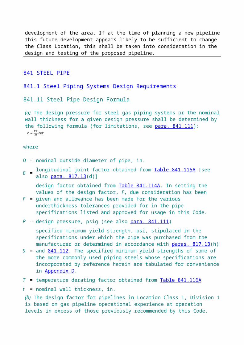
(b) The bends shall be free of buckles, cracks, or other evidence of damage.(c) Changes in direction that cannot be made in accordance with (a) above shall be made with elbow-type fittings.(d) Miter bends are not permitted.(e) Branch connections shall be made only with socket-type tees or other suitable fittings specifically designed for the purpose.
842.45 Field Repairs of Gouges and Grooves.
Injurious gouges or grooves shall be removed by cutting out and replacing the damaged portion as a cylinder or repaired in accordance with para. 852.7.
842.46 Hot Taps.
All hot taps shall be installed by trained and experienced crews.
842.47 Purging.
Purging of plastic mains and service lines shall be done in accordance with the applicable provisions of paras. 841.275 and 841.276.
842.5 Testing Plastic Piping After Construction
842.51 General Provisions.
All plastic piping shall be pressure tested after construction and before being placed in operation to prove its strength and to demonstrate that it does not leak.Tie-Ins. Because it is sometimes necessary to divide a pipeline or main into sections for testing, and to install test heads, connecting piping, and other necessary appurtenances, it is not required that the tie-in sections of piping be tested. The tie-in joints, however, shall be tested for leaks.
842.52 Test Requirements
(a) The test procedure used, including the duration of the test, shall be capable of disclosing all leaks in the section being tested and shall be selected after giving due consideration to the volumetric content of the section and its location.(b) Thermoplastic piping shall not be tested at material temperatures above 140°F, and reinforced thermosetting plastic piping shall not be tested at material temperatures above 150°F. The duration of the test of thermoplastic piping above 100°F, however, shall not exceed 96 hr.(c) Sufficient time for joints to "set" properly must be allowed before the test is initiated.(d) Plastic pipelines and mains shall be tested at a pressure not less than 1.5 times the maximum operating pressure or 50 psig, whichever is greater, except that(1) the test pressure for reinforced thermosetting plastic piping shall not exceed 3.0 times the design pressure of the pipe(2) the test pressure for thermoplastic piping shall not exceed 3.0 times the design pressure of the pipe at temperatures up to and including 100°F or 2.0 times the design pressure at temperatures exceeding 100°F
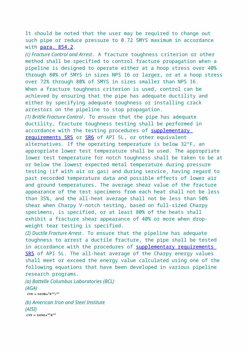
(e) Gas, air, or water may be used as the test medium.
842.53 Safety During Tests.
All testing after construction shall be done with due regard for the safety of employees and the public during the test.
842.6 Copper Mains
842.61 Design of Copper Mains
842.611
When used for gas mains, copper pipe or tubing shall conform to the following requirements:(a) Copper pipe or tubing shall not be used for mains where the pressure exceeds 100 psig.(b) Copper pipe or tubing shall not be used for mains where the gas carried contains more than an average of 0.3 grains of hydrogen sulfide per 100 standard cubic feet of gas. This is equivalent to a trace as determined by the lead acetate test. (See para. 863.4).(c) Copper tubing or pipe for mains shall have a minimum wall thickness of 0.065 in. and shall be hard drawn.(d) Copper pipe or tubing shall not be used for mains where strain or external loading may damage the piping.
842.612 Valves in Copper Piping.
Valves installed in copper lines may be made of any suitable material permitted by this Code.
842.613 Fittings in Copper Piping.
It is recommended that fittings in copper piping and exposed to the soil, such as service tees, pressure control fittings, etc., be made of bronze, copper, or brass.
842.614 Joints in Copper Pipe and Tubing.
Copper pipe shall be joined using either a compression-type coupling or a brazed or soldered lap joint. The filler material used for brazing shall be a copper-phosphorous alloy or silver base alloy. Butt welds are not permissible for joining copper pipe or tubing. Copper tubing shall not be threaded, but copper pipe with wall thickness equivalent to the comparable size of Schedule 40 steel pipe may be threaded and used for connecting screw fittings or valves.
842.615 Protection Against Galvanic Corrosion.
Provision shall be made to prevent harmful galvanic action where copper is connected underground to steel. [See para. 862.114(a).]
842.62 Testing of Copper Mains After Construction
842.621
All copper mains shall be tested after construction in accordance with the provisions of para. 841.35.
843 COMPRESSOR STATIONS
843.1 Compressor Station Design
843.11 Location of Compressor Building.
Except for offshore pipelines, the main compressor building for gas compressor stations should be located at such clear distances from adjacent property not under control of the company as to minimize the hazard of communication of fire to the compressor building from structures on adjacent property. Sufficient open space should be provided around the building to permit the free movement of firefighting equipment.
843.12 Building Construction.
All compressor station buildings that house gas piping in sizes larger than NPS 2 or equipment handling gas (except equipment for domestic purposes) shall be constructed of noncombustible or limited combustible materials as defined in ANSI/NFPA 220.
843.13 Exits.
A minimum of two exits shall be provided for each operating floor of a main compressor building, basements, and any elevated walkway or platform 10 ft or more above ground or floor level. Individual engine catwalks shall not require two exits. Exits of each such building may be fixed ladders, stairways, etc. The maximum distance from any point on an operating floor to an exit shall not exceed 75 ft, measured along the center line of aisles or walkways. Exits shall be unobstructed doorways located so as to provide a convenient possibility of escape and shall provide unobstructed passage to a place of safety. Door latches shall be of a type that can be readily opened from the inside without a key. All swinging doors located in an exterior wall shall swing outward.
843.14 Fenced Areas.
Any fence that may hamper or prevent escape of persons from the vicinity of a compressor station in an emergency shall be provided with a minimum of two gates. These gates shall be located so as to provide a convenient opportunity for escape to a place of safety. Any such gates located within 200 ft of any compressor plant building shall open outward and shall be unlocked (or capable of being opened from the inside without a key) when the area within the enclosure is occupied. Alternatively, other facilities affording a similarly convenient exit from the area may be provided.
843.2 Electrical Facilities
All electrical equipment and wiring installed in gas transmission and distribution compressor stations shall conform to the requirements of ANSI/NFPA 70, insofar as the equipment
commercially available permits.Electrical installations in hazardous locations as defined in ANSI/NFPA 70 and that are to remain in operation during compressor station emergency shut-down as provided in para. 843.431(a) shall be designed to conform to ANSI/NFPA 70 for Class I, Division 1 requirements.
843.4 Compressor Station Equipment
843.41 Gas Treating Facilities
843.411 Liquid Removal.
When condensable vapors are present in the gas stream in sufficient quantity to liquefy under the anticipated pressure and temperature conditions, the suction stream to each stage of compression (or to each unit for centrifugal compressors) shall be protected against the introduction of dangerous quantities of entrained liquids into the compressor. Every liquid separator used for this purpose shall be provided with manually operated facilities for removal of liquids therefrom. In addition, automatic liquid removal facilities, an automatic compressor shutdown device, or a high liquid level alarm shall be used where slugs of liquid might be carried into the compressors.
843.412 Liquid Removal Equipment.
Liquid separators, unless constructed of pipe and fittings and no internal welding is used, shall be manufactured in accordance with Section VIII of the ASME Boiler and Pressure Vessel Code. Liquid separators when constructed of pipe and fittings without internal welding shall be in accordance with Location Class 4 requirements.
843.42 Fire Protection.
Fire protection facilities should be provided in accordance with the American Insurance Association's recommendations. If the fire pumps are a part of such facilities, their operation shall not be affected by emergency shutdown facilities.
(99)843.43 Safety Devices
843.431 Emergency Shutdown Facilities
(a) Each transmission compressor station shall be provided with an emergency shutdown system by means of which the gas can be blocked out of the station and the station gas piping blown down. Operation of the emergency shutdown system also shall cause the shutdown of all gas compressing equipment and all gas-fired equipment. Operation of this system shall deenergize the electrical facilities located in the vicinity of gas headers and in the compressor room, except those that provide emergency lighting for personnel protection and those that are necessary for protection of equipment. The emergency shutdown system shall be operable from any one of at least two locations outside the gas area of the station, preferably near exit gates in the station fence, but not more than 500 ft from the limits of the stations. Blowdown piping shall extend to a location where the discharge of gas is not likely to create a hazard to the compressor station or surrounding area. Unattended field compressor stations of 1,000 hp and less are excluded from the provisions of this paragraph.
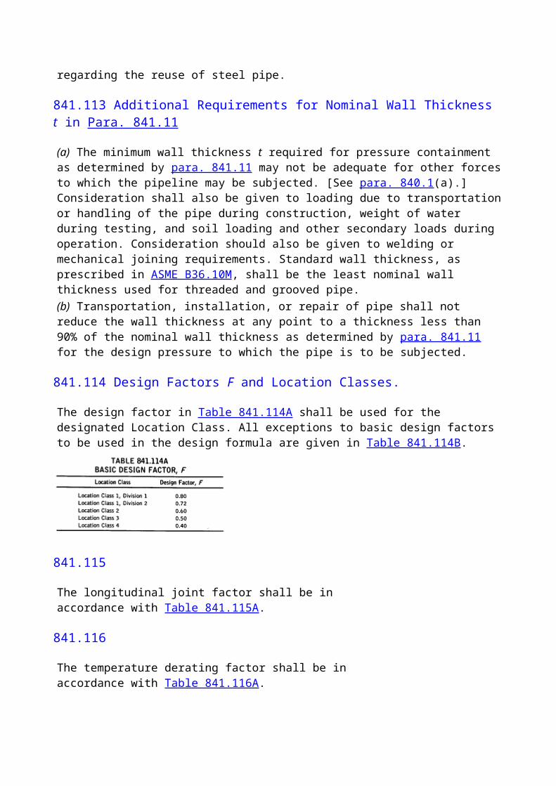
(b) Each compressor station supplying gas directly to a distribution system shall be provided with emergency shutdown facilities located outside the compressor station buildings by means of which all gas can be blocked out of the station, provided there is another adequate source of gas for the distribution system. These shut-down facilities can be either automatic or manually operated as local conditions designate. When no other gas source is available, no shutdown facilities that might function at the wrong time and cause an outage on the distribution system shall be installed.
843.432 Engine Overspeed Stops.
Every compressor prime mover, except electrical induction or synchronous motors, shall be provided with an automatic device that is designed to shut down the unit before the maximum safe speed of either the prime mover or driven unit, as established by the respective manufacturers, is exceeded.
843.44 Pressure Limiting Requirements in Compressor Stations
843.441
Pressure relief or other suitable protective devices of sufficient capacity and sensitivity shall be installed and maintained to ensure that the maximum allowable operating pressure of the station piping and equipment is not exceeded by more than 10%.
843.442
A pressure relief valve or pressure limiting device, such as a pressure switch or unloading device, shall be installed in the discharge line of each positive displacement transmission compressor between the gas compressor and the first discharge block valve. If a pressure relief valve is the primary overprotection device, then the relieving capacity shall be equal to or greater than the capacity of the compressor. If the relief valves on the compressor do not prevent the possibility of overpressuring the pipeline as specified in para. 845, a relieving or pressure limiting device shall be installed on the pipeline to prevent it from being overpressured beyond the limits prescribed by this Code.
843.443 Venting.
Vent lines provided to exhaust the gas from the pressure relief valves to atmosphere shall be extended to a location where the gas may be discharged without undue hazard. Vent lines shall have sufficient capacity so that they will not inhibit the performance of the relief valve.
843.45 Fuel Gas Control.
An automatic device designed to shut off the fuel gas when the engine stops shall be provided on each gas engine operating with pressure gas injection. The engine distribution manifold shall be automatically vented simultaneously.
843.46 Cooling and Lubrication Failures.
All gas compressor units shall be equipped with shutdown or alarm devices to operate in the event
of inadequate cooling or lubrication of the units.
843.47 Explosion Prevention
843.471 Mufflers.
The external shell of mufflers for engines using gas as fuel shall be designed in accordance with good engineering practice and shall be constructed of ductile materials. It is recommended that all compartments of the muffler be manufactured with vent slots or holes in the baffles to prevent gas from being trapped in the muffler.
843.472 Building Ventilation.
Ventilation shall be ample to ensure that employees are not endangered under normal operating conditions (or such abnormal conditions as a blown gasket, packing gland, etc.) by accumulations of hazardous concentrations of flammable or noxious vapors or gases in rooms, sumps, attics, pits, or similarly enclosed places, or in any portion thereof.
(99)843.48 Gas Detection and Alarm Systems
(a) Each compressor building in a compressor station where hazardous concentrations of gas may accumulate shall have a fixed gas detection and alarm system unless the building is(1) constructed so that at least 50% of its upright side area is permanently open to the atmosphere or adequately ventilated by forced or natural ventilation; or(2) in an unattended field compressor station location of 1,000 hp or less and adequately ventilated.(b) Except when shutdown of the system is necessary for maintenance (see para. 853.16), each gas detection and alarm system required by this section shall(1) continuously monitor the compressor building for a concentration of gas in air of not more than 25% of the lower explosive limit(2) warn persons about to enter the building and persons inside the building of the danger if that concentration of gas is exceeded(c) The compressor building configuration shall be considered in selecting the number, type, and placement of detectors and alarms.(d) Alarm signals shall be unique and immediately recognizable, considering background noise and lighting, to personnel who are inside or immediately outside each compressor building.
843.5 Compressor Station Piping
843.51 Gas Piping.
The following are general provisions applicable to all gas piping.
843.511 Specifications for Gas Piping.
All compressor station gas piping, other than instrument, control, and sample piping, to and including connections to the main pipeline shall be of steel and shall use a design factor, F, per Table 841.114B. Valves having shell components made of ductile iron may be used subject to the
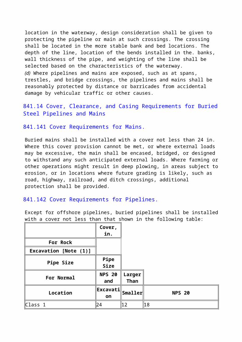
limitations in para. 831.11(b).
843.512 Installation of Gas Piping.
The provisions of para. 841.2 shall apply where appropriate to gas piping in compressor stations.
843.513 Testing of Gas Piping.
All gas piping within a compressor station shall be tested after installation in accordance with the provisions of para. 841.3 for pipelines and mains in Class 3 locations, except that small additions to operating stations need not be tested where operating conditions make it impractical to test.
843.514 Identification of Valves and Piping.
All emergency valves and controls shall be identified by signs. The function of all important gas pressure piping shall be identified by signs or color codes.
843.52 Fuel Gas Piping.
The following are specific provisions applicable to fuel gas piping only.
843.521
All fuel gas lines within a compressor station that serve the various buildings and residential areas shall be provided with master shutoff valves located outside of any building or residential area.
843.522
The pressure regulating facilities for the fuel gas system for a compressor station shall be provided with pressure-limiting devices to prevent the normal operating pressure of the system from being exceeded by more than 25%, or the maximum allowable operating pressure by more than 10%.
843.523
Suitable provision shall be made to prevent fuel gas from entering the power cylinders of an engine and actuating moving parts while work is in progress on the engine or on equipment driven by the engine.
843.524
All fuel gas used for domestic purposes at a compressor station that has an insufficient odor of its own to serve as a warning in the event of its escape shall be odorized as prescribed in para. 871.
843.53 Air Piping System
843.531
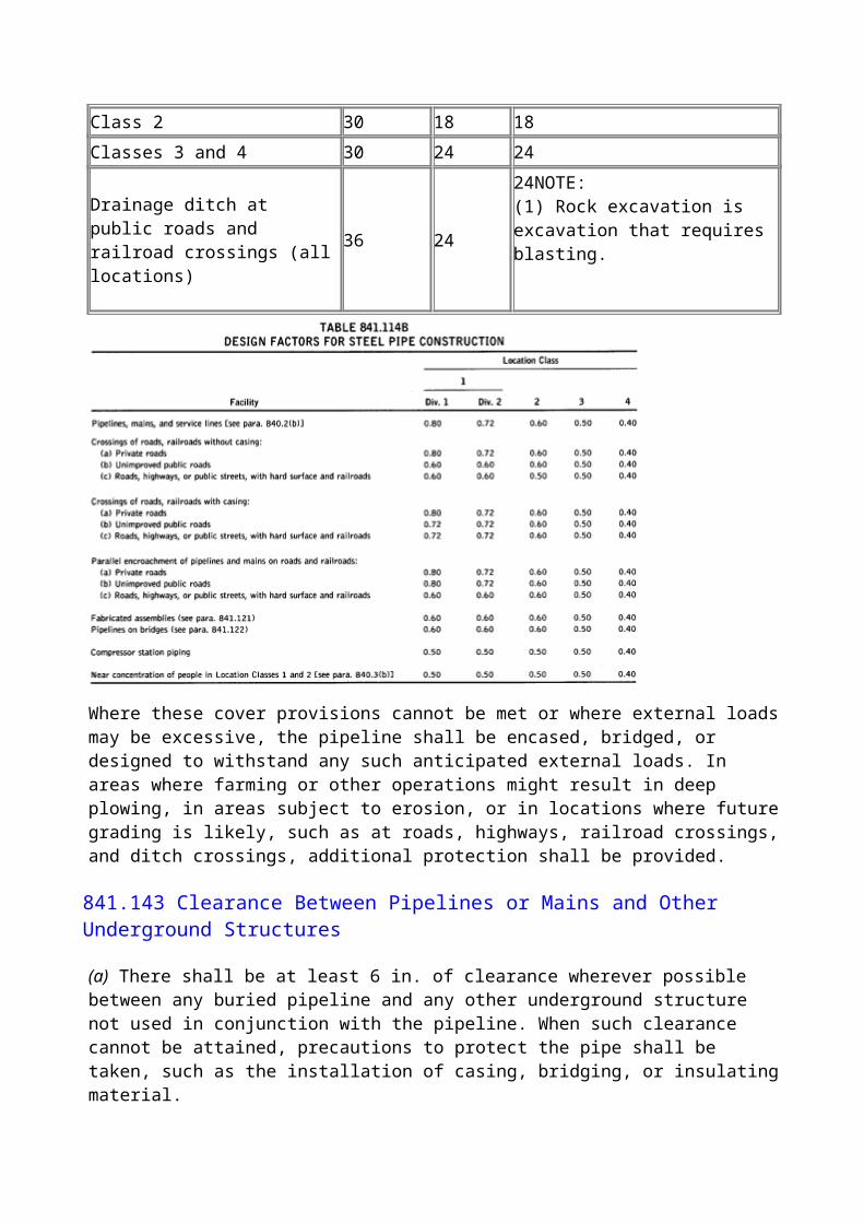
All air piping within gas compressing stations shall be constructed in accordance with ASME B31.3.
843.532
The starting air pressure, storage volume, and size of connecting piping shall be adequate to rotate the engine at the cranking speed and for the number of revolutions necessary to purge the fuel gas from the power cylinder and muffler. The recommendations of the engine manufacturer may be used as a guide in determining these factors. Consideration should be given to the number of engines installed and to the possibility of having to start several of these engines within a short period of time.
843.533
A check valve shall be installed in the starting air line near each engine to prevent backflow from the engine into the air piping system. A check valve shall also be placed in the main air line on the immediate outlet side of the air tank or tanks. It is recommended that equipment for cooling the air and removing the moisture and entrained oil be installed between the starting air compressor and the air storage tanks.
843.534
Suitable provision shall be made to prevent starting air from entering the power cylinders of an engine and actuating moving parts while work is in progress on the engine or on equipment driven by the engines. Acceptable means of accomplishing this are installing a blind flange, removing a portion of the air supply piping, or locking closed a stop valve and locking open a vent downstream from it.
843.535 Air Receivers.
Air receivers or air storage bottles for use in compressor stations shall be constructed and equipped in accordance with Section VIII of the BPV Code.
843.54 Lubricating Oil Piping.
All lubricating oil piping within gas compressing stations shall be constructed in accordance with ASME B31.3.
843.55 Water Piping.
All water piping within gas compressing stations shall be constructed in accordance with ASME B31.1.
843.56 Steam Piping.
All steam piping within gas compressing stations shall be constructed in accordance with ASME B31.1.

843.57 Hydraulic Piping.
All hydraulic power piping within gas compressing stations shall be constructed in accordance with ASME B31.3.
844 PIPE-TYPE AND BOTTLE-TYPE HOLDERS
844.1 Pipe-Type Holders in Rights-of-Way Not Under Exclusive Use and Control of the Operating Company
A pipe-type holder that is to be installed in streets, highways, or in private rights-of-way not under the exclusive control and use of the operating company shall be designed, installed, and tested in accordance with the provisions of this Code applicable to a pipeline installed in the same location and operated at the same maximum pressure.
844.2 Bottle-Type Holders
Bottle-type holders shall be located on land owned or under the exclusive control and use of the operating company.
844.3 Pipe-Type and Bottle-Type Holders on Property Under the Exclusive Use and Control of the Operating Company
844.31
The storage site shall be entirely surrounded with fencing to prevent access by unauthorized persons.
(99)844.32
(a) A pipe-type or bottle-type holder that is to be installed on property under the exclusive control and use of the operating company shall be designed in accordance with construction design factors. The selection of these factors depends on the class location in which the site is situated, the clearance between the pipe containers or bottles and the fence, and the maximum operating pressure, as follows:
Design Factors, FFor Minimum Clearance For Minimum Clearance
Holder Between Containers Between ContainersSize and Fenced and Fenced
Class Boundaries of Site Boundaries of SiteLocation of 25 ft to 100 ft of 100 ft and Over
1 0.72 0.722 0.60 0.723 0.60 0.604 0.40 0.40
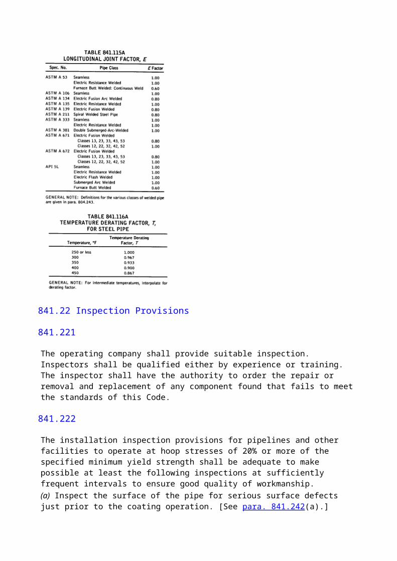
(b) The minimum clearance between containers and the fenced boundaries of the site is fixed by the maximum operating pressure of the holder as follows: Maximum Operating Pressure, psi Minimum Clearance, ftLess than 1,000 251,000 or more 100(c) Minimum Clearance Between Pipe Containers or Bottles. The minimum distance in inches between pipe containers or bottles shall be determined by the following formula:
where
C = minimum clearance between pipe containers or bottles, in.
D = outside diameter of pipe container or bottle, in.
F = design factor [see para. 844.32(a)]
P = maximum allowable operating pressure, psig(d) Pipe containers shall be buried with the top of each container not less than 24 in. below the ground surface.(e) Bottles shall be buried with the top of each container below the normal frost line but in no case closer than 24 in. to the surface.(f) Pipe-type holders shall be tested in accordance with the provisions of para. 841.32 for a pipeline located in the same class location as the holder site, provided, however, that in any case where the test pressure will produce a hoop stress of 80% or more of the specified minimum yield strength of the pipe, water shall be used as the test medium.
844.4 Special Provisions Applicable to Bottle-Type Holders Only
844.41 A bottle-type holder may be manufactured from steel that is not weldable under field conditions, subject to all of the following limitations:
(a) Bottle-type holders made from alloy steel shall meet the chemical and tensile requirements for the various grades of steel in ASTM A 372.(b) In no case shall the ratio of actual yield strength to actual tensile strength exceed 0.85.(c) Welding shall not be performed on such bottles after they have been heat treated and/or stress relieved, except that it shall be permissible to attach small copper wires to the small diameter portion of the bottle end closure for cathodic protection purposes using a localized thermit welding process (charge not to exceed 15 g).(d) Such bottles shall be given a hydrostatic test in the mill and need not be retested hydrostatically at the time of installation. The mill test pressure shall not be less than that required to produce a hoop stress equal to 85% of the specified minimum yield strength of the steel. Careful inspection of the bottles at the time of installation shall be made, and no damaged bottle shall be used.(e) Such bottles and connecting piping shall be tested for tightness after installation using air or gas at a pressure of 50 psi above the maximum operating pressure.
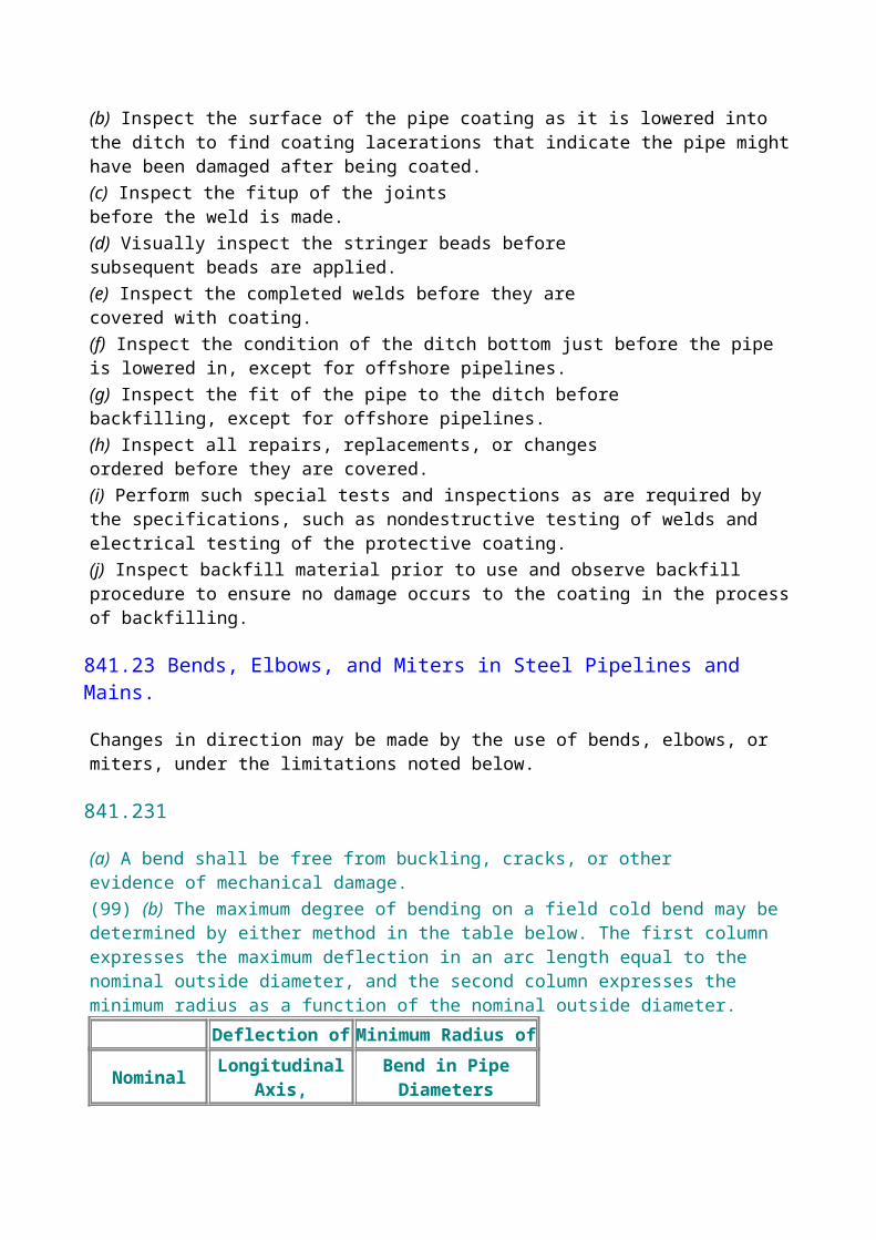
844.5 General Provisions Applicable to Both Pipe-Type and Bottle-Type Holders
(a) No gas containing more than 0.1 grain of hydrogen sulfide per 100 standard cubic feet shall be stored when free water is present or anticipated without employing suitable means to identify, mitigate, or prevent detrimental internal corrosion. (See para. 863.)(b) Provision shall be made to prevent the formation or accumulation of liquids in the holder, connecting piping, and auxiliary equipment that might cause corrosion or interfere with the safe operation of the storage equipment.Relief valves shall be installed in accordance with provisions of this Code that will have relieving capacity adequate to limit the pressure imposed on the filling line and thereby on the storage holder to 100% of the design pressure of the holder or to the pressure that produces a hoop stress of 75% of the specified minimum yield strength of the steel, whichever is the lesser.
845 CONTROL AND LIMITING OF GAS PRESSURE
845.1 Basic Requirement for Protection Against Accidental Overpressuring
Every pipeline, main, distribution system, customer's meter and connected facilities, compressor station, pipe-type holder, bottle-type holder, containers fabricated from pipe and fittings, and all special equipment, if connected to a compressor or to a gas source where the failure of pressure control or other causes might result in a pressure that would exceed the maximum allowable operating pressure of the facility (refer to para. 805.214), shall be equipped with suitable pressure-relieving or pressure-limiting devices. Special provisions for service regulators are set forth in para. 845.24.
845.2 Control and Limiting of Gas Pressure
845.21 Control and Limiting of Gas Pressure in Holders, Pipelines, and All Facilities That Might at Times Be Bottle Tight
845.212
Suitable types of protective devices to prevent overpressuring of such facilities include(a) spring-loaded relief valves of types meeting the provisions of BPV Code, Section VIII(b) pilot-loaded back-pressure regulators used as relief valves, so designed that failure of the pilot system or control lines will cause the regulator to open(c) rupture disks of the type meeting the provisions of BPV Code, Section VIII, Division 1
845.213 Maximum Allowable Operating Pressure for Steel or Plastic Pipelines or Mains.
This pressure is by definition the maximum operating pressure to which the pipeline or main may be subjected in accordance with the requirements of this Code. For a pipeline or main, the maximum allowable operating pressure shall not exceed the lesser of the following four items:
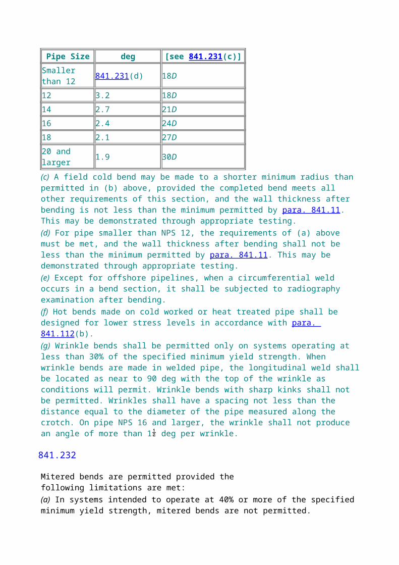
(a) the design pressure (defined in para. 805.212) of the weakest element of the pipeline or main. Assuming that all fittings, valves, and other accessories in the line have an adequate pressure rating, the maximum allowable operating pressure of a pipeline or main shall be the design pressure determined in accordance with para. 841.11 for steel or para. 842.3 for plastic.(b) the pressure obtained by dividing the pressure to which the pipeline or main is tested after construction by the appropriate factor for the Location Class involved, as follows: Location Pressure Pressure
Class For Steel (1) For Plastic
1, Division 1
Test pressure N.A.
1.25 1, Division 2
Test pressure Test pressure
1.10 1.50
2 Test pressure Test pressure
1.25 1.50
3 Test pressure (2)
Test pressure
1.40 1.50
4 Test pressure (2)
Test pressure
1.40
1.50NOTES: (1) See para. 845.214 for test factors applicable to conversion of pipelines with unknown factors. (2) Other factors should be used if the line was tested under the special conditions described in paras. 841.322(d), 841.325, and 841.33. In such cases, use factors that are consistent with the applicable of these sections.
(c) the maximum safe pressure to which the pipeline or main should be subjected based on its operating and maintenance history (for pipelines, see para. 851.1)(d) when service lines are connected to the pipeline or main, the limitations set forth in paras. 845.223(b) and (e)
845.214 Qualification of a Steel Pipeline or Main to Establish the MAOP
(a) Pipeline Operating at 100 psig or More. This paragraph applies to existing natural gas pipelines or to existing pipelines being converted to natural gas service where one or more factors of the steel pipe design formula (see para. 841.11) is unknown, and the pipeline is to be operated at 100 psig or more. The maximum allowable operating pressure shall be determined by hydrostatic testing of the
pipeline.(1) The maximum allowable operating pressure shall be limited to the pressure obtained by dividing the pressure to which the pipeline or main is tested by the appropriate factor for the Location Class involved as follows:
Location Maximum AllowableClass Operating Pressure
1, Division 1 Test pressure 1.251, Division 2 Test pressure 1.392 Test pressure 1.673 Test pressure 2.04 Test pressure 2.5(2) The test pressure to be used in the maximum allowable operating pressure calculation shall be the test pressure obtained at the high elevation point of the minimum strength test section and shall not be higher than the pressure required to produce a stress equal to the yield strength as determined by testing. Only the first test to yield can be used to determine maximum allowable operating pressure.(3) Records of hydrostatic pressure tests and line repairs shall be preserved as long as the facilities involved remain in service.(4) Determine that all valves, flanges, and other pressure rated components have adequate ratings.(5) While the maximum pressure of a test used to establish the maximum allowable working pressure is not limited by this paragraph except by (2) above, due caution should be exercised in selecting the maximum test pressure.(b) Pipelines Operating at Less Than 100 psig. This paragraph applies to existing natural gas pipelines or to existing pipelines being converted to natural gas service where one or more factors of the steel pipe design formula (see para. 841.11) is unknown, and the pipeline is to be operated at less than 100 psig. The maximum allowable operating pressure shall be determined by pressure testing the pipeline.(1) The maximum allowable operating pressure shall be limited to the pressure obtained by dividing the pressure to which the pipeline or main is tested by the appropriate factor for the Location Class involved as follows: Location Maximum Allowable
Class Operating Pressure1 Test pressure 1.252 Test pressure 1.253 Test pressure
1.54 Test pressure 1.5(2) The test pressure to be used in the maximum allowable operating pressure calculation shall be the test pressure obtained at the high elevation point of the minimum strength test section and shall not be higher than the pressure required to produce a stress equal to the yield strength as determined by testing. Only the first test to yield can be used to determine maximum allowable operating pressure.(3) Records of pressure tests and line repairs shall be preserved as long as the facilities involved remain in service.(4) Determine that all valves, flanges, and other pressure rated components have adequate ratings.(5) Although the maximum pressure of a test utilized to establish the maximum allowable working pressure is not limited by this paragraph except by (2) above, due caution should be exercised in selecting the maximum test pressure.
845.22 Control and Limiting of Gas Pressure in High-Pressure Steel, Ductile Iron, Cast Iron, or Plastic Distribution Systems
845.221
Each high-pressure distribution system or main, supplied from a source of gas that is at a higher pressure than the maximum allowable operating pressure for the system, shall be equipped with pressure regulating devices of adequate capacity and designed to meet the pressure, load, and other service conditions under which they will operate or to which they may be subjected.
845.222
In addition to the pressure-regulating devices prescribed in para. 845.221, a suitable method shall be provided to prevent accidental overpressuring of a high-pressure distribution system.Suitable types of protective devices to prevent over pressuring of high-pressure distribution systems include(a) relief valves as prescribed in paras. 845.212(a) and (b)(b) weight-loaded relief valves(c) a monitoring regulator installed in series with the primary pressure regulator(d) a series regulator installed upstream from the primary regulator and set to limit the pressure on the inlet of the primary regulator continuously to the maximum allowable operating pressure of the distribution system or less(e) an automatic shutoff device installed in series with the primary pressure regulator and set to shut off when the pressure on the distribution system reaches the maximum allowable operating pressure or less. This device must remain closed until manually reset. It should not be used where it might cause an interruption in service to a large number of customers.(f) spring-loaded, diaphragm-type relief valves
845.223 Maximum Allowable Operating Pressure for High-Pressure Distribution Systems.

This pressure shall be the maximum pressure to which the system can be subjected in accordance with the requirements of this Code. It shall not exceed(a) the design pressure of the weakest element of the system as defined in para. 805.212(b) 60 psig if the service lines in the system are not equipped with series regulators or other pressure limiting devices as prescribed in para. 845.243(c) 25 psig in cast iron systems having caulked bell and spigot joints, which have not been equipped with bell joint clamps or other effective leak sealing methods(d) the pressure limits to which any joint could be subjected without possibility of parting(e) 2 psig in high-pressure distribution systems equipped with service regulators not meeting the requirements of para. 845.241 and that do not have an overpressure protective device as required in para. 845.242(f) the maximum safe pressure to which the system should be subjected based on its operation and maintenance history
845.23 Control and Limiting of Gas Pressure in Low-Pressure Distribution Systems
845.231
Each low-pressure distribution system or low-pressure main supplied from a gas source that is at a higher pressure than the maximum allowable operating pressure for the low-pressure system shall be equipped with pressure-regulating devices of adequate capacity. These devices must be designed to meet the pressure, load, and other service conditions under which they will have to operate.
845.231
In addition to the pressure-regulating devices prescribed in para. 845.231, a suitable device shall be provided to prevent accidental overpressuring. Suitable types of protective devices to prevent overpressuring of low-pressure distribution systems include(a) a liquid seal relief device that can be set to open accurately and consistently at the desired pressure(b) weight-loaded relief valves(c) an automatic shutoff device as described in para. 845.222(e)(d) a pilot-loaded, back-pressure regulator as described in para. 845.212(b)(e) a monitoring regulator as described in para. 845.222(c)(f) a series regulator as described in para. 845.222(d)
845.233 Maximum Allowable Operating Pressure for Low-Pressure Distribution Systems.
The maximum allowable operating pressure for a low-pressure distribution system shall not exceed either of the following:(a) a pressure that would cause the unsafe operation of any connected and properly adjusted low-pressure gas burning equipment(b) a pressure of 2 psig

845.234 Conversion of Low-Pressure Distribution Systems to High-Pressure Distribution Systems
(a) Before converting a low-pressure distribution system to a high-pressure distribution system, it is required that the following factors be considered(1) the design of the system including kinds of material and equipment used(2) past maintenance records including results of any previous leakage surveys(b) Before increasing the pressure the following steps (not necessarily in sequence shown) shall be taken:(1) Make a leakage survey and repair leaks found.(2) Reinforce or replace parts of the system found to be inadequate for the higher operating pressures.(3) Install a service regulator on each service line, and test each regulator to determine that it is functioning. In some cases it may be necessary to raise the pressure slightly to permit proper operation of the service regulators.(4) Isolate the system from adjacent low-pressure systems.(5) At bends or offsets in coupled or bell and spigot pipe, reinforce or replace anchorages determined to be inadequate for the higher pressures.(c) The pressure in the system being converted shall be increased by steps, with a period to check the effect of the previous increase before making the next increase. The desirable magnitude of each increase and the length of the check period will vary depending on conditions. The objective of this procedure is to afford an opportunity to discover any unknown open and unregulated connections to adjacent low-pressure systems or to individual customers before excessive pressures are reached.
845.24 Control and Limiting of the Pressure of Gas Delivered to Domestic, Small Commercial, and Small Industrial Customers From High-Pressure Distribution Systems
NOTE: When the pressure of the gas and the demand by the customer are greater than those applicable under the provisions of para. 845.24, the requirements for control and limiting of the pressure of gas delivered are included in para. 845.1.
845.241
If the maximum allowable operating pressure of the distribution system is 60 psig or less, and a service regulator having the characteristics listed below is used, no other pressure-limiting device is required:(a) a pressure regulator capable of reducing distribution line pressure, psi, to pressures recommended for household appliances, inches of water column(b) a single port valve with orifice diameter no greater than that recommended by the manufacturer for the maximum gas pressure at the regulator inlet(c) a valve seat made of resilient material designed to withstand abrasion of the gas, impurities in gas, and cutting by the valve, and designed to resist permanent deformation when it is pressed against the valve port(d) pipe connections to the regulator not exceeding 2 NPS
(e) the capability under normal operating conditions of regulating the downstream pressure within the necessary limits of accuracy and of limiting the buildup of pressure under no flow conditions to no more than 50% over the normal discharge pressure maintained under flow conditions(f) a self-contained service regulator with no external static or control lines
845.242
If the maximum allowable operating pressure of the distribution system is 60 psig or less, and a service regulator not having all of the characteristics listed in para. 845.241 is used, or if the gas contains materials that seriously interfere with the operation of service regulators, suitable protective devices shall be installed to prevent unsafe overpressuring of the customer's appliances, should the service regulator fail. Some of the suitable types of protective devices to prevent overpressuring of the customers' appliances are
(a) a monitoring regulator
(b) a relief valve
(c) an automatic shutoff device
These devices may be installed as an integral part of the service regulator or as a separate unit.
845.243
If the maximum allowable operating pressure of the distribution system exceeds 60 psig, suitable methods shall be used to regulate and limit the pressure of the gas delivered to the customer to the maximum safe value. Such methods may include(a) a service regulator having the characteristics listed in para. 845.241 and a secondary regulator located upstream from the service regulator. In no case shall the secondary regulator be set to maintain a pressure higher than 60 psi. A device shall be installed between the secondary regulator and the service regulator to limit the pressure on the inlet of the service regulator to 60 psi or less in case the secondary regulator fails to function property. This device may be either a relief valve or an automatic shut off that shuts if the pressure on the inlet of the service regulator exceeds the set pressure (60 psi or less) and remains closed until manually reset.(b) a service regulator and a monitoring regulator set to limit to a maximum safe value the pressure of the gas delivered to the customer(c) a service regulator with a relief valve vented to the outside atmosphere, with the relief valve set to open so that the pressure of gas going to the customer shall not exceed a maximum safe value. The relief valve may be either built into the service regulator or may be a separate unit installed downstream from the service regulator. This combination may be used alone only in cases where the inlet pressure on the service regulator does not exceed the manufacturer's safe working pressure rating of the service regulator, and it is not recommended for use where the inlet pressure on the service regulator exceeds 125 psi. For higher inlet pressures, the method in para. 845.243(a) or (b) should be used.
845.3 Requirements for Design of Pressure Relief and Pressure Limiting Installations
845.31
Pressure relief or pressure-limiting devices except rupture disks shall(a) be constructed of materials such that the operation of the device will not normally be impaired by corrosion of external parts by the atmosphere or internal parts by gas(b) have valves and valve seats that are designed not to stick in a position that will make the device inoperative and result in failure of the device to perform in the manner for which it was intended(c) be designed and installed so that they can be readily operated to determine if the valve is free, can be tested to determine the pressure at which they will operate, and can be tested for leakage when in the closed position.
845.311
Rupture discs shall meet the requirements for design as set out in BPV Code, Section VIII, Division 1.
845.32
The discharge stacks, vents, or outlet ports of all pressure relief devices shall be located where gas can be discharged into the atmosphere without undue hazard. Consideration should be given to all exposures in the immediate vicinity. Where required to protect devices, the discharge stacks or vents shall be protected with rain caps to preclude the entry of water.
845.33
The size of the openings, pipe, and fittings located between the system to be protected and the pressure-relieving device and the vent line shall be of adequate size to prevent hammering of the valve and to prevent impairment of relief capacity.
845.34
Precautions shall be taken to prevent unauthorized operation of any stop valve that will make a pressure relief valve inoperative. This provision shall not apply to valves that will isolate the system under protection from its source of pressure. Acceptable methods for complying with this provision are as follows:(a) Lock the stop valve in the open position. Instruct authorized personnel of the importance of not inadvertently leaving the stop valve closed and of being present during the entire period that the stop valve is closed so that they can lock it in the open position before they leave the location.(b) Install duplicate relief valves, each having adequate capacity by itself to protect the system, and arrange the isolating valves or three-way valve so that mechanically it is possible to render only one safety device inoperative at a time.
845.35
Precautions shall be taken to prevent unauthorized operation of any valve that will make pressure limiting devices inoperative. This provision applies to isolating valves, bypass valves, and valves on control or float lines that are located between the pressure limiting device and the system that the device protects. A method similar to para. 845.34(a) shall be considered acceptable in
complying with this provision.
845.36
(a) When a monitoring regulator, series regulator, system relief, or system shutoff is installed at a district regulator station to protect a piping system from over pressuring, the installation shall be designed and installed to prevent any single incident, such as an explosion in a vault or damage by a vehicle, from affecting the operation of both the overpressure protective device and the district regulator. (See paras. 846 and 847.)(b) Special attention shall be given to control lines. All control lines shall be protected from failing objects, excavations by others, or other foreseeable causes of damage and shall be designed and installed to prevent damage to any one control line from making both the district regulator and the overpressure protective device inoperative.
845.4 Capacity of Pressure Relieving and Pressure Limiting Station and Devices
845.41 Required Capacity of Pressure Relieving and Pressure Limiting Stations
(99)845.411
Each pressure relief station, pressure limiting station, or group of such stations installed to protect a piping system or pressure vessel shall have sufficient capacity and shall be set to operate to prevent the pressure from exceeding the following levels.(a) Systems With Pipe or Pipeline Components Operating Over 72% of the SMYS. The required capacity is the maximum allowable operating pressure plus 4%.(b) Systems With Pipe or Pipeline Components Operating at or Below 72% of the SMYS Other Than in Low-Pressure Distribution Systems. The required capacity is the lesser of the following two items:(1) the maximum allowable operating pressure plus 10%(2) the pressure that produces a hoop stress of 75% of the specified minimum yield strength(c) Low-Pressure Distribution Systems. The required capacity is a pressure that would cause the unsafe operation of any connected and properly adjusted gas burning equipment.
845.412
When more than one pressure regulating or compressor station feeds into the pipeline or distribution system and pressure relief devices are installed at such stations, the relieving capacity at the remote station may be taken into account in sizing the relief devices at each station. In doing this, however, the assumed remote relieving capacity must be limited to the capacity of the piping system to transmit gas to the remote location or to the capacity of the remote relief device, whichever is less.
845.42 Proof of Adequate Capacity and Satisfactory Performance of Pressure Limiting and Pressure Relief Devices
(99)845.421
Where the safety device consists of an additional regulator that is associated with or functions in combination with one or more regulators in a series arrangement to control or limit the pressure in a piping system, suitable checks shall be made. These checks shall be conducted to determine that the equipment will operate in a satisfactory manner to prevent any pressure in excess of the established maximum allowable operating pressure of the system, should any one of the associated regulators malfunction or remain in the wide-open position.
845.5 Instrument, Control, and Sample Piping
(a) Scope(1) The requirements given in this section apply to the design of instrument, control, and sampling piping for safe and proper operation of the piping itself and do not cover design of piping to secure proper functioning of instruments for which the piping is installed.(2) This section does not apply to permanently closed piping systems, such as fluid-filled, temperature- responsive devices.(b) Materials and Design(1) The materials employed for valves, fittings, tubing, and piping shall be designed to meet the particular conditions of service.(2) Takeoff connections and attaching bosses, fittings, or adapters shall be made of suitable material and shall be capable of withstanding the maximum service pressure and temperature of the piping or equipment to which they are attached. They shall be designed to satisfactorily withstand all stresses without failure by fatigue.(3) A shutoff valve shall be installed in each takeoff line as near as practicable to the point of takeoff. Blowdown valves shall be installed where necessary for the safe operation of piping, instruments, and equipment. (4) Brass pipe or copper pipe or tubing shall not be used for metal temperatures greater than 400°F.(5) Piping subject to clogging from solids or deposits shall be provided with suitable connections for cleaning.(6) Pipe or tubing required under this section may be specified by the manufacturers of the instrument, control apparatus, or sampling device, provided that the safety of the pipe or tubing as installed is at least equal to that otherwise required under the Code.(7) Piping that may contain liquids shall be protected by heating or other suitable means from damage due to freezing.(8) Piping in which liquids may accumulate shall be provided with drains or drips.(9) The arrangement of piping and supports shall be designed to provide not only for safety under operating stresses, but also to provide protection for the piping against detrimental sagging, external mechanical injury, abuse, and damage due to unusual service conditions other than those connected with pressure, temperature, and service vibration.(10) Suitable precautions shall be taken to protect against corrosion. (See para. 863.)(11) Joints between sections of tubing and/or pipe, between tubing and/or pipe and valves or fittings shall be made in a manner suitable for the pressure and temperature conditions, such as by means of flared, flareless, and compression type fittings, or equal, or they may be of the brazed, screwed, or socket-welded type. If screwed-end valves are to be used with flared, flareless, or compression type fittings, adapters are required.Slip type expansion joints shall not be used; expansion shall be compensated for by providing flexibility within the piping or tubing system itself.
(12) Plastic shall not be used where operating temperatures exceed limitations shown in paras. 842.32(b) and 842.33(b).(13) Plastic piping shall not be painted. If identification other than that already provided by the manufacturer's marking is required, it shall be accomplished by other means.
845.6 Uprating
This section of the Code prescribes minimum requirements for uprating pipelines or mains to higher maximum allowable operating pressures.
845.61General
(a) A higher maximum allowable operating pressure established under this section may not exceed the design pressure of the weakest element in the segment to be uprated. It is not intended that the requirements of this Code be applied retroactively to such items as road crossings, fabricated assemblies, minimum cover, and valve spacings. Instead, the requirements for these items shall meet the criteria of the operating company before the uprating is performed.(b) A plan shall be prepared for uprating that shall include a written procedure that will ensure compliance with each applicable requirement of this section.(c) Before increasing the maximum allowable operating pressure of a segment that has been operating at a pressure less than that determined by para. 845.213, the following investigative and corrective measures shall be taken:(1) The design, initial installation, method, and date of previous testing, Location classes, materials, and equipment shall be reviewed to determine that the proposed increase is safe and consistent with the requirements of this Code.(2) The condition of the line shall be determined by leakage surveys, other field inspections, and examination of maintenance records.(99) (3) Repairs, replacements, or alterations disclosed to be necessary by subparas. (c)(1) and (c)(2) above shall be made prior to the uprating.(d) A new test according to the requirements of this Code should be considered if satisfactory evidence is not available to ensure safe operation at the proposed maximum allowable operating pressure.(e) When gas upratings are permitted under paras. 845.62, 845.63, 845.64, and 845.65, the gas pressure shall be increased in increments, with a leak survey performed after each incremental increase. The number of increments shall be determined by the operator after considering the total amount of the pressure increase, the stress level at the final maximum allowable operating pressure, the known condition of the line, and the proximity of the line to other structures. The number of increments shall be sufficient to ensure that any leaks are detected before they can create a potential hazard. Potentially hazardous leaks discovered shall be repaired before further increasing the pressure. A final leak survey shall be conducted at the higher maximum allowable operating pressure.(f) Records for uprating, including each investigation required by this section, corrective action taken, and pressure test conducted, shall be retained as long as the facilities involved remain in service.
845.62 Uprating Steel Pipelines or Mains to a Pressure That Will Produce a Hoop Stress of 30% or More of SMYS.
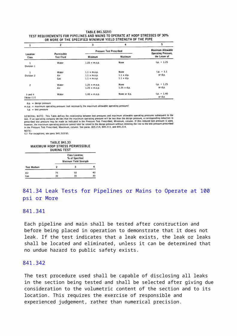
The maximum allowable operating pressure may be increased after compliance with para. 845.61(c) and one of the following provisions:(a) If the physical condition of the line as determined by para. 845.61(c) indicates the line is capable of withstanding the desired higher operating pressure, is in general agreement with the design requirements of this Code, and has previously been tested to a pressure equal to or greater than that required by this Code for a new line for the proposed maximum allowable operating pressure, the line may be operated at the higher maximum allowable operating pressure.(b) If the physical condition of the line as determined by para. 845.61(c) indicates that the ability of the line to withstand the higher maximum operating pressure has not been satisfactorily verified or that the line has not been previously tested to the levels required by this Code for a new line for the proposed higher maximum allowable operating pressure, the line may be operated at the higher maximum allowable operating pressure if it shall successfully withstand the test required by this Code for a new line to operate under the same conditions.(c) If the physical condition of the line as determined by para. 845.61(c) verifies its capability of operating at a higher pressure, a higher maximum allowable operating pressure may be established according to para. 845.213 using as a test pressure the highest pressure to which the line has been subjected, either in a strength test or in actual operation.(d) If it is necessary to test a pipeline or main before it can be uprated to a higher maximum allowable operating pressure, and if it is not practical to test the line either because of the expense or difficulties created by taking it out of service or because of other operating conditions, a higher maximum allowable operating pressure may be established in Location Class 1 as follows.(1) Perform the requirements of para. 845.61(c).(2) Select a new maximum allowable operating pressure consistent with the condition of the line and the design requirements of this Code, provided(a) the new maximum allowable operating pressure does not exceed 80% of that permitted for a new line to operate under the same conditions(b) the pressure is increased in increments as provided in para. 845.61(e)
845.63 Uprating Steel or Plastic Pipelines to a Pressure That Will Produce a Hoop Stress Less Than 30% of SMYS
(a) This applies to high-pressure steel mains and pipelines where the higher maximum allowable operating pressure is less than that required to produce a hoop stress of 30% of the specified minimum yield strength of the pipe and to all high-pressure plastic distribution systems. If the higher maximum allowable operating pressure of a steel pipeline or main is more than 30% of the specified minimum yield strength of the pipe, the provisions of para. 845.62 shall apply.(b) Before increasing the maximum allowable operating pressure of a system that has been operating at less than the applicable maximum pressure to a higher maximum allowable operating pressure, the following factors shall be considered:(1) the physical condition of the line as determined by para. 845.61(c)(2) information from the manufacturer or supplier determining that each component of a plastic system is capable of performing satisfactorily at the higher pressure.(c) Before increasing the pressure, the following steps shall be taken:(1) Install suitable devices on the service lines to regulate and limit the pressure of the gas in accordance with para. 845.243 if the new maximum allowable operating pressure is to be over 60 psi.(2) Adequately reinforce or anchor offsets, bends, and dead ends in coupled pipe to avoid movement of the pipe should the offset, bend, or dead end be exposed in an excavation.
(3) Increase pressure in increments as provided in para. 845.61(e).
845.64 Uprating a Ductile Iron High-Pressure Main or System to a New and Higher Maximum Allowable Operating Pressure
(a) The maximum allowable operating pressure of a ductile iron main or system shall not be increased to a pressure in excess of that permitted in para. 842.211. Where records are not complete enough to permit the direct application of para. 842.211, the following procedures shall be used.(1) Laying Condition. Where the original laying conditions cannot be ascertained, it shall be assumed that Condition D (pipe supported on blocks, tamped backfill) exists for cast iron pipe and Condition B (pipe laid without blocks, tamped backfill) exists for ductile iron pipe. (2) Cover. Unless the actual maximum cover depth is known with certainty, it shall be determined by exposing the main or system at three or more points and making actual measurements. The main or system shall be exposed in areas where the cover depth is most likely to be greatest. The greatest measured cover depth shall be used for computations.(3) Nominal Wall Thickness. Unless the nominal thickness is known with certainty, it shall be determined with ultrasonic measuring devices. The average of all measurements taken shall be increased by the allowance indicated in the following table:
Allowance, in.Cast Iron Pipe Ductile
Nominal Pit Cast Centrifugally Cast IronPipe Size Pipe Pipe Pipe
3-8 0.075 0.065 0.06510-12 0.08 0.07 0.0714-24 0.08 0.08 0.07530-42 0.09 0.09 0.07548 0.09 0.09 0.0854-60 0.09 ... ... The nominal wall thickness of cast iron shall be the standard thickness listed in Table 10 or Table 11 - whichever is applicable - of AWWA C101 that is nearest the value obtained. The nominal wall thickness of ductile iron shall be the standard thickness listed in Table 6 of ANSI/AWWA C150/A21.50 nearest the value obtained.(4) Manufacturing Process. Unless the cast iron pipe manufacturing process is known with certainty, it shall be assumed to be pit cast pipe having a bursting tensile strength, S, of 11,000 psi and a modulus of rupture, R, of 31,000 psi.(b) Before increasing the maximum allowable operating pressure, the following measures shall be taken:(1) Review the physical condition as required by para. 845.61(c).(2) Adequately reinforce or anchor offsets, bends, and dead ends in coupled or bell and spigot pipe to avoid movement of the pipe, should the offset, bend, or dead end be exposed by excavation.(3) Install suitable devices on the service lines to regulate and limit the pressure of the gas in accordance with para. 845.243 if the new and higher maximum allowable operating pressure is to be over 60 psig.(c) If after compliance with paras. 845.64(a) and (b), it is established that the main system is capable of safely withstanding the proposed new and higher maximum allowable operating
pressure, the pressure shall be increased as provided in para. 845.61(e).
845.65 Uprating a Distribution System That Has Been Operating at Inches of Water (Low-Pressure) to a Higher Pressure
(a) In addition to the precautions outlined in para. 845.61(c) and the applicable requirements contained in paras. 845.63 and 845.64, the following steps must be taken.(1) Install pressure regulating devices at each customer's meter.(2) Verify that the segment being uprated is physically disconnected from all segments of line that will continue to operate at inches of water.(b) After performing the steps outlined in (a) above, the pressure shall be increased in increments as outlined in para. 845.61(e). After the first incremental increase, however, steps shall be taken to verify that the customer's regulators are performing satisfactorily.
846 VALVES7
846.1 Required Spacing of Valves
846.11 Transmission Lines
(a) Except for offshore installations, sectionalizing block valves shall be installed in new transmission pipelines at the time of construction. When determining the sectionalizing valve spacing, primary consideration shall be given to locations that provide continuous accessibility to the valves. Other factors involve the conservation of gas, time to blow down the isolated section, continuity of gas service, necessary operating flexibility, expected future development within the valve spacing section, and significant natural conditions that may adversely affect the operation and security of the line.(b) Notwithstanding the considerations in (a) above, the spacing between valves on a new transmission line shall not exceed the following:(1) 20 miles in areas of predominantly Location Class 1(2) 15 miles in areas of predominantly Location Class 2(3) 10 miles in areas of predominantly Location Class 3(4) 5 miles in areas of predominantly Location Class 4(c) The spacing defined in (b) above may be adjusted slightly to permit a valve to be installed in a more accessible location, with continuous accessibility being the primary consideration.
846.12
Valves on distribution mains, whether for operating or emergency purposes, shall be spaced as follows:(a) High-Pressure Distribution Systems. Valves shall be installed in high-pressure distribution systems in accessible locations to reduce the time to shut down a section of main in an emergency. In determining the spacing of the valves, consideration should be given to the operating pressure and size of the mains and local physical conditions as well as the number and type of consumers that might be affected by a shutdown.(b) Low-Pressure Distribution Systems. Valves may be used on low-pressure distribution systems but are not required except as specified in para. 846.22(a).
846.2 Location of Valves
846.21 Transmission Valves
(a) Sectionalizing block valves shall be accessible and protected from damage and tampering. If a blowdown valve is involved, it shall be located where the gas can be blown to the atmosphere without undue hazard.(b) Sectionalizing valves may be installed above ground, in a vault, or buried. In all installations an operating device to open or close the valve shall be readily accessible to authorized persons. All valves shall be suitably supported to prevent settlement or movement of the attached piping.(c) Blowdown valves shall be provided so that each section of pipeline between main line valves can be blown down. The sizes and capacity of the connections for blowing down the line shall be such that under emergency conditions the section of line can be blown down as rapidly as is practicable.(d) This Code does not require the use of automatic valves nor does the Code imply that the use of automatic valves presently developed will provide full protection to a piping system. Their use and installation shall be at the discretion of the operating company.
846.22 Distribution System Valves
(a) A valve shall be installed on the inlet piping of each regulator station controlling the flow or pressure of gas in a distribution system. The distance between the valve and the regulator or regulators shall be sufficient to permit the operation of the valve during an emergency, such as a large gas leak or a fire in the station.(b) Valves on distribution mains, whether for operating or emergency purposes shall be located in a manner that will provide ready access and facilitate their operation during an emergency. Where a valve is installed in a buried box or enclosure, only ready access to the operating stem or mechanism is implied. The box or enclosure shall be installed in a manner to avoid transmitting external loads to the main.
847 VAULTS
847.1 Structural Design Requirements
Underground vaults or pits for valves, pressure relieving, pressure limiting or pressure regulating stations, etc., shall be designed and constructed in accordance with the following provisions:(a) Vaults and pits shall be designed and constructed in accordance with good structural engineering practice to meet the loads that may be imposed on them.(b) Sufficient working space shall be provided so that all of the equipment required in the vault can be properly installed, operated, and maintained.(c) In the design of vaults and pits for pressure limiting, pressure relieving, and pressure regulating equipment, consideration shall be given to the protection of the installed equipment from damage, such as that resulting from an explosion within the vault or pit that may cause portions of the roof or cover to fall into the vault.(d) Pipe entering and within regulator vaults or pits shall be steel for NPS 10 and smaller sizes, except that control and gage piping may be copper. Where piping extends through the vault or pit structure, provision shall be made to prevent the passage of gases or liquids through the opening
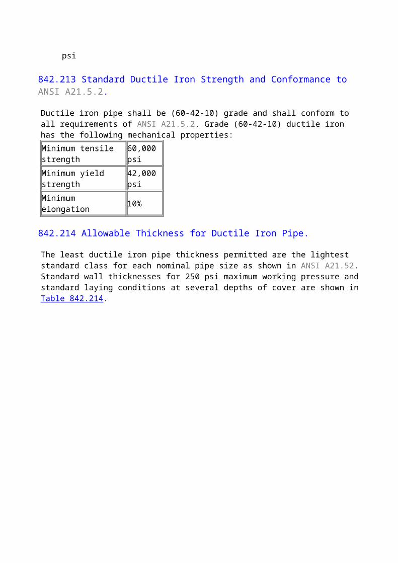
and to avert strains in the piping. Equipment and piping shall be suitably sustained by metal, masonry, or concrete supports. The control piping shall be placed and supported in the vault or pit so that its exposure to injury or damage is reduced to a minimum.(e) Vault or pit openings shall be located so as to minimize the hazards of tools or other objects failing on the regulator, piping, or other equipment. The control piping and the operating parts of the equipment installed shall not be located under a vault or pit opening where workmen can step on them when entering or leaving the vault or pit, unless such parts are suitably protected.(f) Whenever a vault or pit opening is to be located above equipment that could be damaged by a failing cover, a circular cover should be installed, or other suitable precautions should be taken.
847.2 Accessibility
Accessibility shall be considered in selecting a site for a vault. Some of the important factors to consider in selecting the location of a vault are as follows:(a) Exposure to Traffic. The location of vaults in street intersections or at points where traffic is heavy or dense should be avoided.(b) Exposure to Flooding. Vaults should not be located at points of minimum elevation, near catch basins, or where the access cover will be in the course of surface waters.(c) Exposure to Adjacent Subsurface Hazards. Vaults should be located as far as is practical from water, electric, steam, or other facilities.
847.3 Vault Sealing, Venting, and Ventilation
Underground vaults and closed top pits containing either a pressure regulating or reduction station, or a pressure limiting or relieving station shall be sealed, vented, or ventilated as follows:(a) When the internal volume exceeds 200 cu ft, such vaults or pits shall be ventilated with two ducts each having at least the ventilating effect of an NPS 4 pipe.(b) The ventilation provided shall be sufficient to minimize the possible formation of a combustible atmosphere in the vault or pit. Vents associated with the pressure regulating or pressure relieving equipment must not be connected to the vault or pit ventilation.(c) The ducts shall extend to a height above grade adequate to disperse any gas-air mixtures that might be discharged. The outside end of the ducts shall be equipped with a suitable weatherproof fitting or vent head designed to prevent foreign matter from entering or obstructing the duct. The effective area of the opening in such fittings or vent heads shall be at least equal to the cross-sectional area of an NPS 4 duct. The horizontal section of the ducts shall be as short as practical and shall be pitched to prevent the accumulation of liquids in the line. The number of bends and offsets shall be reduced to a minimum, and provisions shall be incorporated to facilitate the periodic cleaning of the ducts.(d) Such vaults or pits having an internal volume between 75 cu ft and 200 cu ft may be either sealed, vented, or ventilated. If sealed, all openings shall be equipped with tight-fitting covers without open holes through which an explosive mixture might be ignited. Means shall be provided for testing the internal atmosphere before removing the cover. If vented, the proper provision to prevent external sources of ignition from reaching the vault atmosphere must be provided. If ventilated, the provisions of either subparas. (a), (b), and (c) above or (e) below shall apply.(e) If vaults or pits referred to in (d) above are ventilated by means of openings in the covers or gratings, and the ratio of the internal volume in cubic feet to the effective ventilating area of the cover or grating in square feet is less than 20 to 1, no additional ventilation is required.(f) Vaults or pits having an internal volume less than 75 cu ft have no specific requirements.
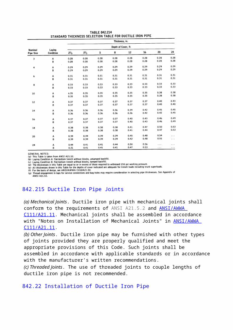
847.4 Drainage and Waterproofing
(a) Provisions shall be made to minimize the entrance of water into vaults. Nevertheless, vault equipment shall always be designed to operate safely, if submerged.(b) No vault containing gas piping shall be connected by means of a drain connection to any other substructure, such as a sewer.(c) Electrical equipment in vaults shall conform to the requirements of Class 1, Group D, of ANSI/NFPA 70.
848 CUSTOMERS' METERS AND REGULATORS
848.1 Location for Customers' Meter and Regulator Installations
(a) Customers' meters and regulators may be located either inside or outside of buildings, depending on local conditions, except that on service lines requiring series regulation, in accordance with para. 845.243(a), the upstream regulator shall be located outside of the building.(b) When installed within a building, the service regulator shall be in a readily accessible location near the point of gas service line entrance, and whenever practical, the meters shall be installed at the same location. Neither meters nor regulators shall be installed in bedrooms, closets, or bathrooms; under combustible stairways; in unventilated or inaccessible places; or closer than 3 ft to sources of ignition, including furnaces and water heaters. On service lines supplying large industrial customers or installations where gas is used at higher than standard service pressure, the regulators may be installed at other readily accessible locations.(c) When located outside of buildings, meters and service regulators shall be installed in readily accessible locations where they will be reasonably protected from damage.(d) Regulators requiring vents for their proper and effective operation shall be vented to the outside atmosphere in accordance with the provisions of para. 848.33. Individual vents shall be provided for each regulator.
848.2 Operating Pressures for Customers' Meter Installations
Iron or aluminum case meters shall not be used at a maximum operating pressure higher than the manufacturer's rating for the meter. New tinned steel case meters shall not be used at a pressure in excess of 50% of the manufacturer's test pressure; rebuilt tinned steel case meters shall not be used at a pressure in excess of 50% of the pressure used to test the meter after rebuilding.
848.3 Protection of Customers' Meter and Regulator Installations from Damage
848.31
Meters and service regulators shall not be installed where rapid deterioration from corrosion or other causes is likely to occur, unless proven measures are taken to protect against such deterioration.
848.32
A suitable protective device, such as a back pressure regulator or a check valve, shall be installed
downstream of the meter if and as required under the following conditions:(a) If the nature of the utilization equipment is such that it may induce a vacuum at the meter, install a back-pressure regulator downstream from the meter.(b) Install a check valve or equivalent if(1) the utilization equipment might induce a back pressure(2) the gas utilization equipment is connected to a source of oxygen or compressed air(3) liquefied petroleum gas or other supplementary gas is used as standby and might flow back into the meter. A three-way valve, installed to admit the standby supply and at the same time shut off the regular supply, can be substituted for a check valve if desired.
848.33
All service regulator vents and relief vents, where required, shall terminate in the outside air in rain- and insect-resistant fittings. The open end of the vent shall be located where the gas can escape freely into the atmosphere and away from any openings into the buildings if a regulator failure resulting in the release of gas occurs. At locations where service regulators might be submerged during floods, either a special antiflood type breather vent fitting shall be installed or the vent line shall be extended above the height of the expected flood waters.
848.34
Pits and vaults housing customers' meters and regulators shall be designed to support vehicular traffic when installed in the following locations:(a) travelled portions of alleys, streets, and highways(b) driveways
848.4 Installation of Meters and Regulators
All meters and regulators shall be installed in such a manner as to prevent undue stresses on the connecting piping and/or the meter. Lead (Pb) connections or other connections made of material that can be easily damaged shall not be used. The use of standard weight close (all thread) nipples is prohibited.
849 GAS SERVICE LINES
849.1 General Provisions Applicable to Steel, Copper, and Plastic Service Lines
849.11 Installation of Service Lines
(a) Service lines shall be installed at a depth that will protect them from excessive external loading and local activities, such as gardening. It is required that a minimum of 12 in. of cover be provided in private property and a minimum of 18 in. of cover be provided in streets and roads. Where these cover requirements cannot be met due to existing substructures, less cover is permitted provided such portions of these service lines that are subject to excessive superimposed loads are cased or bridged or the pipe is appropriately strengthened.(b) Service lines shall be properly supported at all points on undisturbed or well-compacted soil so
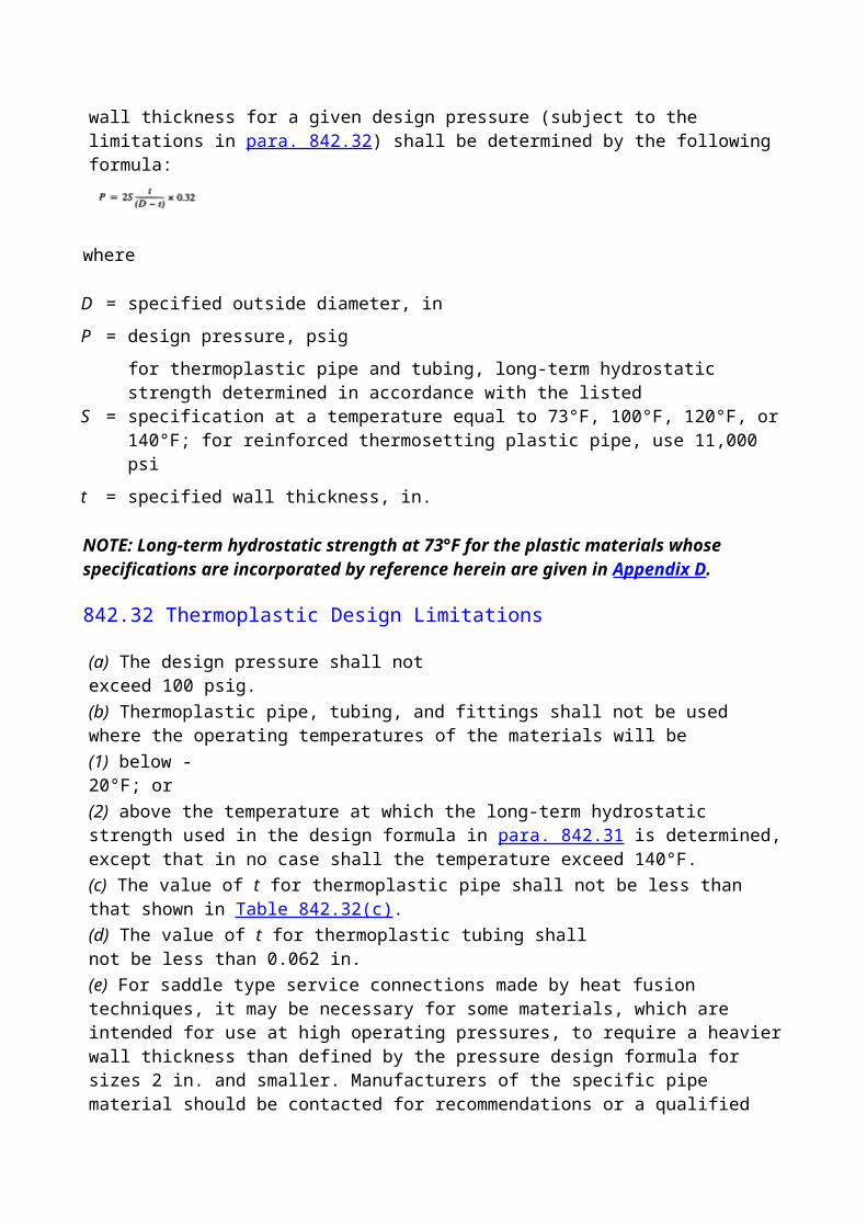
that the pipe will not be subject to excessive external loading by the backfill. The material used for the backfill shall be free of rocks, building materials, etc., that might cause damage to the pipe or the protective coating.(c) Where there is evidence of condensate in the gas in sufficient quantities to cause interruptions in the gas supply to the customer, the service line shall be graded so as to drain into the main or to drips at the low points in the service line.
849.12 Types of Valves Suitable for Service Line Valves
(a) Valves used as service line valves shall meet the applicable requirements of paras. 810 and 831.1.(b) The use of soft seat service line valves is not recommended when the design of the valves is such that exposure to excessive heat could adversely affect the ability of the valve to prevent the flow of gas.(c) A valve incorporated in a meter bar that permits the meter to be bypassed does not qualify under this Code as a service line valve.(d) Service line valves on high-pressure service lines, installed either inside buildings or in confined locations outside buildings where the blowing of gas would be hazardous, shall be designed and constructed to minimize the possibility of the removal of the core of the valve accidentally or willfully with ordinary house hold tools.(e) The operating company shall make certain that the service line valves installed on high-pressure service lines are suitable for this use either by making their own tests or by reviewing the tests made by the manufacturers.(f) On service lines designed to operate at pressures in excess of 60 psig, the service line valves shall be the equivalent of a pressure lubricated valve or a needle type valve. Other types of valves may be used where tests by the manufacturer or by the user indicate that they are suitable for this kind of service.
849.13 Location of Service Line Valves
(a) Service line valves shall be installed on all new service lines (including replacements) in a location readily accessible from the outside.(b) Valves shall be located upstream of the meter if there is no regulator, or upstream of the regulator, if there is one.(c) All service lines operating at a pressure greater than 10 psig and all service lines NPS 2 or larger shall be equipped with a valve located on the service line outside of the building, except that whenever gas is supplied to a theater, church, school, factory, or other building where large numbers of persons assemble, an outside valve will be required, regardless of the size of the service line or the service line pressure.(d) Underground valves shall be located in a covered durable curb box or standpipe designed to permit ready operation of the valve. The curb box or standpipe shall be supported independently of the service line.
849.14 Location of Service Line Connections to Main Piping.
It is recommended that service lines be connected to either the top or the side of the main. The connection to the top of the main is preferred to minimize the possibility of dust and moisture being carried from the main into the service line.
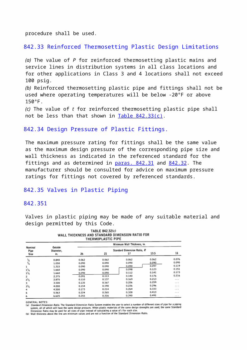
849.15 Testing of Service Lines After Construction
849.151 General Provisions.
Each service line shall be tested after construction and before being placed in service to demonstrate that it does not leak. The service line connection to the main need not be included in this test if it is not feasible to do so.
849.152 Test Requirements
(a) Service lines to operate at a pressure of less than 1 psig, which do not have a protective coating capable of temporarily sealing a leak, shall be given a standup air or gas pressure test at not less than 10 psig for at least 5 min.(b) Service lines to operate at a pressure of less than 1 psig, which have a protective coating that might temporarily seal a leak, and all service lines to operate at a pressure of 1 psig or more, shall be given a standup air or gas pressure test for at least 5 min at the proposed maximum operating pressure or 90 psig, whichever is greater. Service lines of steel, however, that are stressed to 20% or more of the specified minimum yield strength shall be tested in accordance with the requirements for testing mains. (See para. 841.3.)(c) The requirements of (a) and (b) above shall apply to plastic service lines, except that plastic service lines shall be tested to at least 1.5 times the maximum operating pressure, and the limitations on maximum test pressure, temperature, and duration set forth in para. 842.52 shall be observed.
849.2 Steel Service Lines
849.21 Design of Steel Service Lines
(a) Steel pipe, when used for service lines, shall conform to the applicable requirements of Chapter I.(b) Steel service pipe shall be designed in accordance with the requirements of paras. 841.11 and 841.121. Where the pressure is less than 100 psig, the steel service pipe shall be designed for at least 100 psig pressure.(c) Steel pipe used for service lines shall be installed in such a manner that the piping strain or external loading shall not be excessive.(d) All underground steel service lines shall be joined by threaded and coupled joints, compression-type fittings, or by qualified welding or brazing methods, procedures, and operators.
849.22 Installation of Steel Service Lines
849.221 Installation of Steel Service Lines in Bores
(a) When coated steel pipe is to be installed as a service line in a bore, care shall be exercised to prevent damage to the coating during installation.(b) When a service line is to be installed by boring or driving, and coated steel pipe is to be used, it shall not be used as the bore pipe or drive pipe and left in the ground as part of the service line unless it has been demonstrated that the coating is sufficiently durable to withstand the boring or driving operation in the type of soil involved without significant damage to the coating. Where
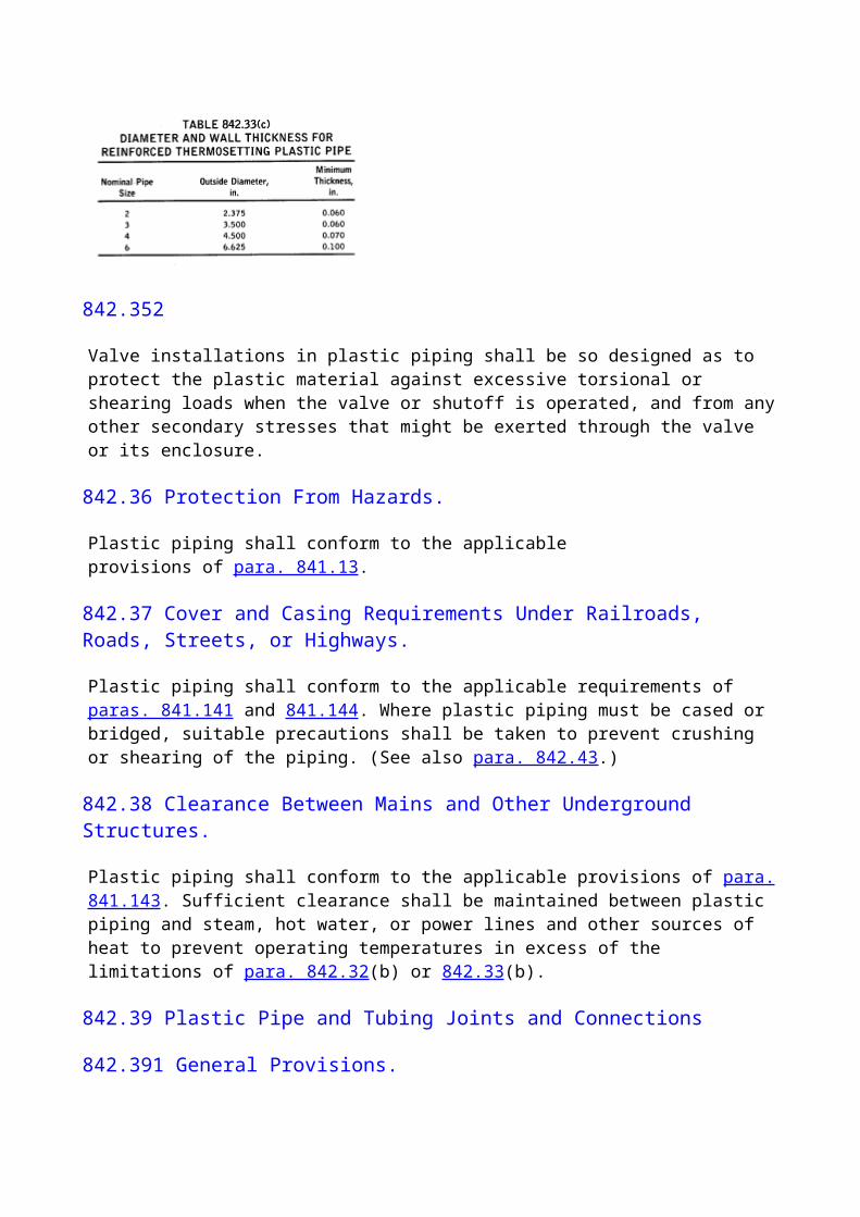
significant damage to the coating may result from boring or driving, the coated service line should be installed in an oversized bore or casing pipe of sufficient diameter to accommodate the service pipe.(c) In exceptionally rocky soil, coated pipe shall not be inserted through an open bore if significant damage to the coating is likely.
849.222 Installation of Service Lines Into or Under Buildings
(a) Underground steel service lines, when installed below grade through the outer foundation wall of a building, shall be either encased in a sleeve or otherwise protected against corrosion. The service line and/or sleeve shall be sealed at the foundation wall to prevent entry of gas or water into the building.(b) Steel service lines, where installed underground under buildings, shall be encased in a gas-tight conduit. When such a service line supplies the building it subtends, the conduit shall extend into a normally usable and accessible portion of the building. At the point where the conduit terminates, the space between the conduit and the service line shall be sealed to prevent the possible entrance of any gas leakage. The casing shall be vented at a safe location.
849.3 Ductile Iron Service Lines
849.31 Use of Ductile Iron Service Lines.
When used for service lines, ductile iron pipe shall meet the applicable requirements of para. 842. Ductile iron pipe may be used for service lines except for the portion of the service line that extends through the building wall. Ductile iron service lines shall not be installed in unstable soils or under buildings.
849.4 Plastic Service Lines
849.41 Design of Plastic Service Lines
(a) Plastic pipe and tubing shall be used for service lines only where the piping strain or external loading will not be excessive.(b) Plastic pipe, tubing, cements, and fittings used for service lines shall conform to the applicable requirements of Chapter I.(c) Plastic service lines shall be designed in accordance with the applicable requirements of para. 842.3.(d) Plastic service lines shall be joined in accordance with the applicable requirements of para. 842.39.
849.42 Installation of Plastic Service Lines
(a) Plastic service lines shall be installed in accordance with the applicable requirements of paras. 842.4 and 849.11. Particular care must be exercised to prevent damage to plastic service line piping at the connection to the main or other facility. Precautions shall be taken to prevent crushing or shearing of plastic piping due to external loading or settling of backfill and to prevent damage or pullout from the connection resulting from thermal expansion or contraction. (See paras. 842.431 and 842.432).
(b) Notwithstanding the limitations imposed in para. 842.43, a plastic service line may terminate above ground and outside the building, provided that(1) the above-ground portion of the plastic service line is completely enclosed in a conduit or casing of sufficient strength to provide protection from external damage and deterioration. Where a flexible conduit is used, the top of the riser must be attached to a solid support. The conduit or casing shall extend a minimum of 6 in. below grade.(2) the plastic service line is not subjected to external loading stresses by the customer's meter or its connecting piping.
849.421 Installation of Plastic Service Lines Into or Under Buildings
(a) An underground plastic service line installed through the outer foundation or wall of a building shall be encased in a rigid sleeve with suitable protection from shearing action or backfill settlement. The sleeve shall extend past the outside face of the foundation a sufficient distance to reach undisturbed soil or thoroughly compacted backfill. At the point where the sleeve terminates inside the foundation or wall, the space between the sleeve and the service line shall be sealed to prevent leakage into the building. The plastic service line shall not be exposed inside the building.(b) A plastic service line installed underground under a building shall be encased in a gas-tight conduit. When such a service line supplies the building it subtends, the conduit shall extend into a normally usable and accessible portion of the building. At the point where the conduit terminates, the space between the conduit and the service line shall be sealed to prevent leakage into the building. The plastic service line shall not be exposed inside the building. The casing shall be vented at a safe location.
849.5 Copper Service Lines
849.51 Design of Copper Service Lines
849.511
Copper pipe or tubing, when used for service lines, shall conform to the following requirements:(a) Copper pipe or tubing shall not be used for service lines where the pressure exceeds 100 psig.(b) Copper pipe or tubing shall not be used for service lines where the gas carried contains more than an average of 0.3 grains of hydrogen sulfide per 100 standard cubic feet of gas. This is equivalent to a trace as determined by the lead-acetate test. (See para. 863.4.)(c) The minimum wall thickness for copper pipe or tubing used for service lines, shall be not less than type "L" as specified in ASTM B 88.(d) Copper pipe or tubing shall not be used for service lines where strain or external loading may damage the piping.
849.512 Valves in Copper Piping.
Valves installed in copper service lines may be made of any suitable material permitted by this Code.
849.513 Fittings in Copper Piping.
It is recommended that fittings in copper piping and exposed to the soil, such as service line tees,
pressure control fittings, etc., be made of bronze, copper, or brass.
849.514 Joints in Copper Pipe and Tubing.
Copper pipe shall be joined by using either a compression type coupling or a brazed or soldered lap joint. The filler material used for brazing shall be a copper phosphorous alloy or silver base alloy. Butt welds are not permissible for joining copper pipe or tubing. Copper tubing shall not be threaded, but copper pipe with a wall thickness equivalent to the comparable size of Schedule 40 steel pipe may be threaded and used for connecting screw fittings or valves.
849.515 Protection Against Galvanic Action Caused by Copper.
Provisions shall be made to prevent harmful galvanic action where copper is connected underground to steel. [See para. 862.114(a).]
849.52 Installation of Copper Service Lines.
The following requirements shall apply to copper service lines within buildings.(a) Copper service lines may be installed within buildings, provided that the service line is not concealed and is suitably protected against external damage.(b) An underground copper service line installed through the outer foundation wall of a building shall be either encased in a sleeve or otherwise protected against corrosion. The annular space between the service line and sleeve shall be sealed at the foundation wall to prevent entry of gas or water.(c) A copper service line installed underground under buildings shall be encased in a conduit designed to prevent gas leaking from the service line from getting into the building. When joints are used, they shall be of brazed or soldered type in accordance with para. 849.514.
849.6 Service Line Connections to Mains
849.61 Service Line Connections to Steel Mains. Service lines may be connected to steel mains by
(a) welding a service line tee or similar device to the main(b) using a service line clamp or saddle(c) using compression fittings with rubber or rubber like gaskets or welded connections to connect the service line to the main connection fitting. Gaskets used in a manufactured gas system shall be of a type that effectively resists that type of gas.(d) welding a steel service line directly to the main (see para. 831.42 and Table 831.42)
849.62 Service Line Connection to Cast Iron and Ductile Iron Mains
(a) Service lines may be connected to cast iron and ductile iron mains by(1) drilling and tapping the main, provided the diameter of the tapped hole shall not exceed the limitations imposed by para. 831.33(b); or(2) using a reinforcing sleeve
(b) Service line connections shall not be brazed directly to cast iron or ductile iron mains.
849.621
Compression fittings using rubber or rubber-like gaskets or welded connections may be used to connect the service line to the main connection fitting. Gaskets used in a manufactured gas system shall be of a type that effectively resists that type of gas.
849.63 Service Line Connections to Plastic Mains
(a) Plastic or metal service lines shall be connected to plastic mains with suitable fittings.(b) A compression-type service line to main connection shall be designed and installed to effectively sustain the longitudinal pullout forces caused by contraction of the piping or external loading.
849.64 Service Line Connections to Copper Mains
(a) Connections using a copper or cast bronze service line tee or extension fitting sweat-brazed to the copper main are recommended for copper mains.(b) Butt welds are not permitted.(c) Fillet-brazed joints are not recommended.(d) The requirements of para. 849.514 shall apply to(1) joints not specifically mentioned above(2) all brazing material
849.65 Plastic Service Line Connections to Metal Mains
(a) Plastic service lines shall be connected to metal mains with a suitable metallic or plastic main fitting as provided in para. 849.61,849.62, or 849.64 having a compression end or other suitable transition fitting.(b) A compression-type service line to main connection shall be designed and installed to effectively sustain the longitudinal pullout forces caused by contraction of the piping or external loading.
CHAPTER V OPERATING AND MAINTENANCE PROCEDURES
850 OPERATING AND MAINTENANCE PROCEDURES AFFECTING THE SAFETY OF GAS TRANSMISSION AND DISTRIBUTION FACILITIES
850.1 General
(a) Because of many variables, it is not possible to prescribe in a code a detailed set of operating and maintenance procedures that will encompass all cases. It is possible, however, for each operating company to develop operating and maintenance procedures based on the provisions of this Code, its experience, and its knowledge of its facilities and conditions under which they are operated that will be adequate from the stand point of public safety. For operating and maintenance procedures relating to corrosion control, see Chapter VI.
(b) Upon initiating gas service in a pipeline designed and constructed or converted to gas service in accordance with this Code, the operating company shall determine the Location Class in accordance with Table 854.1(c).
850.2 Basic Requirements
Each operating company having gas transmission or distribution facilities within the scope of this Code shall(a) have a written plan covering operating and maintenance procedures in accordance with the scope and intent of this Code(b) have a written emergency plan covering facility failure or other emergencies(c) operate and maintain its facilities in conformance with these plans(d) modify the plans periodically as experience dictates and as exposure of the public to the facilities and changes in operating conditions require(e) provide training for employees in procedures established for their operating and maintenance functions. The training shall be comprehensive and shall be designed to prepare employees for service in their area of responsibility.(f) keep records to administer the plans and training properly
850.3 Essential Features of the Operating and Maintenance Plan
The plan prescribed in para. 850.2(a) shall include(a) detailed plans and instructions for employees covering operating and maintenance procedures for gas facilities during normal operations and repairs(b) items recommended for inclusion in the plan for specific classes of facilities that are given in paras. 851.2, 851.3, 851.4, 851.5, 851.6, and 861(d)(c) plans to give particular attention to those portions of the facilities presenting the greatest hazard to the public in the event of an emergency or because of construction or extraordinary maintenance requirements(d) provisions for periodic inspections along the route of existing steel pipelines or mains, operating at a hoop stress in excess of 40% of the specified minimum yield strength of the pipe material to consider the possibility of Location Class changes. It is not intended that these inspections include surveys of the number of buildings intended for human occupancy. (See para. 854.)
850.4 Essential Features of the Emergency Plan
850.41 Written Emergency Procedures
850.411
Each operating company shall establish written procedures that will provide the basis for instructions to appropriate operating and maintenance personnel that will minimize the hazard resulting from a gas pipeline emergency. At a minimum, the procedures shall provide for the following:(a) a system for receiving, identifying, and classifying emergencies that require immediate response by the operating company(b) indicating clearly the responsibility for instructing employees in the procedures listed in the
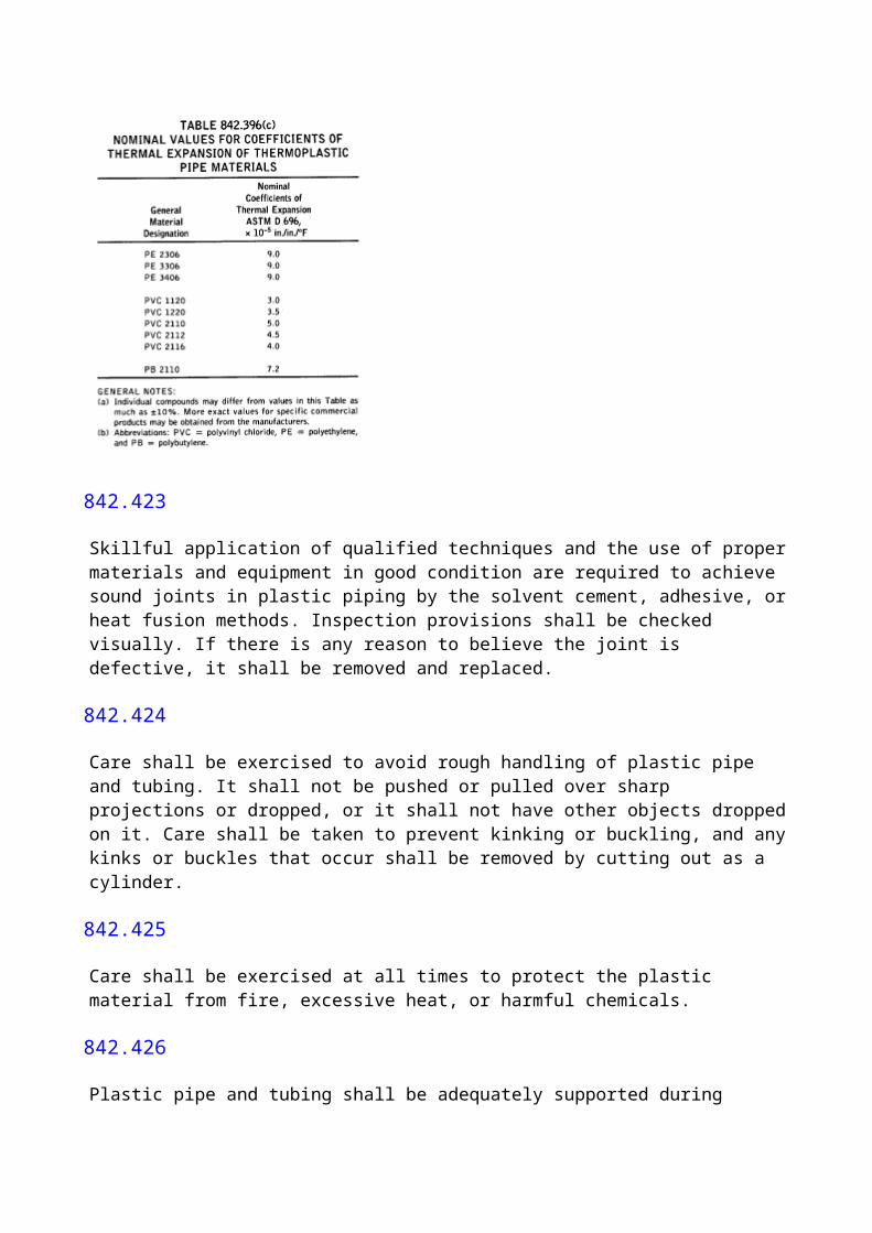
emergency plans and for training employees in the execution of those procedures(c) indicating clearly those responsible for updating the plan(d) establishing a plan for prompt and adequate handling of all calls that concern emergencies whether they are from customers, the public, company employees, or other sources(e) establishing a plan for the prompt and effective response to a notice of each type of emergency(f) controlling emergency situations, including the action to be taken by the first employee arriving at the scene(g) the dissemination of information to the public(h) the safe restoration of service to all facilities affected by the emergency after proper corrective measures have been taken(i) reporting and documenting the emergency
850.42 Training Program.
Each operating company shall have a program for informing, instructing, and training employees responsible for executing emergency procedures. The program shall acquaint the employee with the emergency procedures and how to promptly and effectively handle emergency situations. The program may be implemented by oral instruction, written instruction, and, in some instances, group instruction, followed by practice sessions. The program shall be established and maintained on a continuing basis with provision for updating as necessitated by revision of the written emergency procedures. Program records shall be maintained to establish what training each employee has received and the date of such training.
850.43 Liaison.
Each operating company shall establish and maintain liaison with appropriate fire, police, and other public officials and public communications media.
850.44 Educational Program.
An educational program shall be established to enable customers and the general public to recognize and report a gas emergency to the appropriate officials. The educational program called for under this section should be tailored to the type of pipeline operation and the environment traversed by the pipeline and should be conducted in each language that is significant in the community served. Operators of distribution systems should communicate their programs to consumers and the general public in their distribution area. Operators of transmission systems should communicate their programs to residents along their pipeline rights-of-way. The programs of operators in the same area should be coordinated to properly direct reports of emergencies and to avoid inconsistencies.
850.5 Pipeline Failure Investigation
Each operating company shall establish procedures to analyze all failures and accidents for determining the cause and to minimize the possibility of a recurrence. This plan shall include a procedure to select samples of the failed facility or equipment for laboratory examination when necessary.
850.6 Prevention of Accidental Ignition

Smoking and all open flames shall be prohibited in and around structures, or areas under the control of the operating company containing gas facilities (such as compressor stations, meter and regulator stations, and other gas handling equipment), where possible leakage of gas constitutes a hazard of fire or explosion. Each operating company shall take steps to minimize the danger of accidental ignition of gas.(a) When a hazardous amount of gas is to be vented into open air, each potential source of ignition shall first be removed from the area and adequate fire extinguishers shall be provided. All flashlights, lighting fixtures, extension cords, and tools shall be of a type approved for hazardous atmospheres. Blowdown connections that will direct the gas away from any electrical transmission lines must be installed or used.(b) Suitable signs and flagmen or guards, if necessary, shall be posted to warn others approaching or entering the area of the hazard.(c) To prevent accidental ignition by electric arcing, an adequate bonding cable should be connected to each side of any piping that is to be parted or joined, and any cathodic protection rectifiers in the area shall be turned off. When plastic pipe is being parted or joined, a spray of water or use of wet rags is advised to cover the surface to prevent static arcing.(d) When cutting by torch or welding is to be performed, a thorough check shall first be made for the presence of a combustible gas mixture in the area outside of the pipeline. If found, the mixture shall be eliminated before starting welding or cutting. Monitoring of the air mixture should continue throughout the progress of the work.(e) Should welding be anticipated on a pipeline filled with gas and the safety check under (d) above has been completed satisfactorily, the gas pressure must be controlled by a suitable means to keep a slight positive pressure in the pipeline at the welding area before starting work. Precautions should be taken to prevent a backdraft from occurring at the welding area.(f) Before cutting by torch or welding on a line that may contain a mixture of gas and air, it shall be made safe by displacing the mixture with gas, air, or an inert gas. Caution must be taken when using an inert gas to provide adequate ventilation for all workers in the area.
850.7 Blasting Effects
Each operating company shall establish procedures for protection of facilities in the vicinity of blasting activities. The operating company shall(a) locate and mark its pipeline when explosives are to be detonated within distances as specified in company plans. Consideration should be given to the marking of minimum blasting distances from the pipelines depending upon the type of blasting operation.(b) determine the necessity and extent of observing or monitoring blasting activities based upon the proximity of the blast with respect to the pipelines, the size of charge, and soil conditions(c) conduct a leak survey following each blasting operation near its pipelines.
851 PIPELINE MAINTENANCE
(99)851.1 Periodic Surveillance of Pipelines
As a means of maintaining the integrity of its pipeline system, each operating company shall establish and implement procedures for periodic surveillance of its facilities. Studies shall be initiated and appropriate action shall be taken where unusual operating and maintenance conditions occur, such as failures, leakage history, drop in flow efficiency due to internal corrosion, or
substantial changes in cathodic protection requirements.When such studies indicate the facility is in unsatisfactory condition, a planned program shall be initiated to abandon, replace, or recondition and proof test. If such a facility cannot be reconditioned or phased out, the maximum allowable operating pressure shall be reduced commensurate with the requirements described in para. 945.213(c).
851.2 Pipeline Patrolling
Each operating company shall maintain a periodic pipeline patrol program to observe surface conditions on and adjacent to each pipeline right-of-way, indications of leaks, construction activity other than that performed by the company, natural hazards, and any other factors affecting the safety and operation of the pipeline. Patrols shall be performed at least once every year in Locations Classes 1 and 2, at least once every 6 months in Location Class 3, and at least once every 3 months in Location Class 4. Weather, terrain, size of line, operating pressures, and other conditions will be factors in determining the need for more frequent patrol. Main highways and railroad crossings shall be inspected with greater frequency and more closely than pipelines in open country.
851.21 Maintenance of Cover at Road Crossings and Drainage Ditches.
The operating company shall determine by periodic surveys if the cover over the pipeline at road crossings and drainage ditches has been reduced below the requirements of the original design. If the operating company determines that the normal cover provided at the time of pipeline construction has become unacceptably reduced due to earth removal or line movement, the operating company shall provide additional protection by providing barriers, culverts, concrete pads, casing, lowering of the line, or other suitable means.
851.22 Maintenance of Cover in Cross-Country Terrain.
If the operating company learns, as a result of patrolling, that the cover over the pipeline in cross country terrain does not meet the original design, it shall determine whether the cover has been reduced to an unacceptable level. If level is unacceptable, the operating company shall provide additional protection by replacing cover, lowering the line, or other suitable means.
851.3 Leakage Surveys
Each operating company of a transmission line shall provide for periodic leakage surveys of the line in its operating and maintenance plan. The types of surveys selected shall be effective for determining if potentially hazardous leakage exists. The extent and frequency of the leakage surveys shall be determined by the operating pressure, piping age, class location, and whether the transmission line transports gas without an odorant.
(99)851.4 Repair Procedures for Steel Pipelines Operating at Hoop Stress Levels at or Above 40% of the Specified Minimum Yield Strength
If at any time a defect mentioned in the following subsections of para. 851.4 is evident on a pipeline operating at or above 40% of the specified minimum yield strength of the pipe, temporary measures shall be employed immediately to protect the property and the public. If it is not feasible
to make permanent repairs at the time of discovery, permanent repairs shall be made as soon as feasible as described herein. The use of a welded patch as a repair method is prohibited, except as provided in para. 851.43(e). If the pipeline is not taken out of service, the operating pressure shall be at a level that will provide safety during the repair operations.Gouges and grooves are defined as injurious when the depth of the defect is greater than 10% of the nominal wall thickness of the pipe. See para. 841.113(b) for additional limitations. Smooth dents in existing pipelines do not require repair unless they(a) contain a stress concentrator, such as a scratch, gouge, groove, or arc burn;(b) affect the curvature of the pipe at the longitudinal weld or a circumferential weld; or(c) exceed a maximum depth of 6% of nominal pipe diameter.Nonleaking corroded areas that must be repaired or replaced are defined in para. 862.213. Longitudinal weld seams are commonly identified by visual inspection, etchants, and ultrasonics.A full encirclement welded split sleeve shall have a design pressure at least equal to that required for the maximum allowable operating pressure of the pipe being repaired. If conditions require that the sleeve carry the full longitudinal stresses, the sleeve shall be at least equal to the design strength of the pipe being repaired. Full encirclement sleeves shall not be less than 4 in. in width.If the defect is not a leak, the circumferential fillet welds are optional in certain cases as described in the following subsections of para. 851.4. If circumferential fillet welds are made, the sleeve's longitudinal welds should be butt welds. The welding procedures for the circumferential fillet welds shall be suitable for the materials and shall consider the potential for underbead cracking. Backup strips are not required. If the circumferential fillet welds are not made, the longitudinal welds may be butt welds or fillets to a side bar. The circumferential edges, which would have been sealed had the fillet welds been made, should be sealed with a coating material such as enamel or mastic, so that the soil environment will be kept out of the area under the sleeve.
851.41 Permanent Field Repairs of Injurious Gouges, Grooves, and Dents
(a) Injurious gouges, grooves, and dents shall be removed or reinforced, or the operating pressure shall be reduced.(1) If feasible, gouges, grooves, and dents shall be removed by taking the pipeline out of service and cutting out a cylindrical piece of pipe and replacing same with pipe of equal or greater design pressure.(2) If not feasible to take the pipeline out of service or operate at a reduced pressure, repairs may be made(a) with a full encirclement welded split sleeve with or without circumferential fillet welds;(b) by removing the defect by hot tapping, provided the entire defect is removed; or(c) if the defect is not a dent, by grinding as provided for in para. 841.242. If after the defect is removed by grinding not enough wall thickness remains [see para. 841.113(b)], a full encirclement welded split sleeve, with or without circumferential fillet welds, shall be installed.(3) If a dent is repaired with a sleeve and circumferential fillet welds are not made, the dent shall first be filled with a hardenable filler. If fillet welds are made, the dent may be protected either by the filler just mentioned or by intentionally pressurizing the sleeve by hot tapping the pipeline under it.(b) All repairs under para. 851.41(a) shall pass nondestructive inspections and tests as provided in para. 851.5.
851.42 Permanent Field Repair of Welds Having Injurious Defects
(a) All circumferential butt welds found to have unacceptable defects (according to API 1104) shall be repaired in accordance with the requirements of para. 827, provided the pipeline can be taken out of service. Repairs on welds may be made while the pipeline is in service, provided the weld is not leaking, the pressure in the pipeline has been reduced to a pressure that will not produce a stress in excess of 20% of the specified minimum yield of the pipe, and grinding of the defective area can be limited so that there will remain at least in. thickness in the pipe weld.(b) Defective welds mentioned in (a) above, which cannot be repaired under (a) above and where it is not feasible to remove the defect from the pipeline by replacement, may be repaired by the installation of a full encirclement welded split sleeve using circumferential fillet welds.(c) If a gouge, groove, or dent occurs in a submerged arc welded seam (or a manufacturing defect is found in such a seam) or if a gouge, groove, or dent occurs in a circumferential butt weld, a full encirclement welded split sleeve shall be installed with or without using fillet welds. Dents shall be protected by a filler or by pressurizing the sleeve as previously described in para. 851.41(a)(3).(d) If a gouge, groove, or dent occurs in an electric resistance weld seam or a flash weld seam, if a manufacturing defect is discovered in same, or if hydrogen stress cracking is found in any weld zone, a full encirclement welded split sleeve shall be installed using fillet welds. The sleeve shall then be pressurized by hot tapping the pipeline under the sleeve.(e) All repairs performed under (a), (b), (c), and (d) above shall be tested and inspected as provided in para. 851.5.
851.43 Permanent Field Repair of Leaks and Nonleaking Corroded Areas
(a) If feasible, the pipeline shall be taken out of service and repaired by cutting out a cylindrical piece of pipe and replacing with pipe of equal or greater design strength.(b) If it is not feasible to take the pipeline out of service, repairs shall be made by the installation of a full encirclement welded split sleeve unless a patch is chosen in accordance with (e) below, or unless corrosion is repaired with deposited weld metal in accordance with (f) below. If nonleaking corrosion is repaired with a full encirclement welded split sleeve, the circumferential fillet welds are optional.(c) If the leak is due to a corrosion pit, the repair may be made by the installation of a properly designed bolt-on leak clamp.(d) A small leak may be repaired by welding a nipple over it to vent the gas while welding and then installing an appropriate fitting on the nipple.(e) Leaking or nonleaking corroded areas on pipe of not more than 40,000 psi specified minimum yield strength may be repaired by using a steel plate patch with rounded comers and with dimensions not in excess of one-half the circumference of the pipe fillet welded over the pitted area. The design strength of the plate shall be the same or greater than the pipe.(f) Small corroded areas may be repaired by filling them with deposited weld metal from low-hydrogen electrodes. The higher the pressure and the greater the flow rate, the less is the chance of burn-through. At 20 V and 100 A, burn-through is unlikely to occur when the following actual wall thicknesses exist:
Gas Velocity, ft/secpsia 0 5 10 2015 0.320 ... ... ... 500 0.300 0.270 0.240 0.205900 0.280 0.235 0.190 0.150
This method of repair should not be attempted on pipe that is thought to be susceptible to brittle fracture.(g) All repairs performed under (a), (b), and (d) above shall be tested and inspected as provided in 851.5.
851.44 Permanent Field Repair of Hydrogen Stress Cracking in Hard Spots and Stress Corrosion Cracking
(a) If feasible, the pipeline shall be taken out of service and repaired by cutting out a cylindrical piece of pipe and replacing with pipe of equal or greater design strength.(b) If it is not feasible to take the pipeline out of service, repairs shall be made by the installation of a full encirclement welded split sleeve. In the case of stress corrosion cracking, the fillet welds are optional. If the fillet welds are made, pressurization of the sleeve is optional. The same applies to hydrogen stress cracking in hard spots except that a flat hard spot shall be protected with a hardenable filler or by pressurization of a fillet welded sleeve.(c) All repairs performed under (a) and (b) above shall be tested and inspected as provided in para. 851.5.
851.5 Testing Repairs to Steel Pipelines or Mains Operating at Hoop Stress Levels at or Above 40% of the Specified Minimum Yield Strength
851.51 Testing of Replacement Pipe Sections.
When a scheduled repair to a pipeline or main is made by cutting out the damaged portion of the pipe as a cylinder and replacing it with another section of pipe, the replacement section of pipe shall be subjected to a pressure test. The replacement section of pipe shall be tested to the pressure required for a new pipeline or main installed in the same location. The tests may be made on the pipe prior to installation, provided nondestructive tests meeting the requirements of para. 826 are made on all field girth butt welds after installation. If the replacement is made under controlled fire conditions (gas in the pipeline), full encirclement welded split sleeves may be used to join the pipe sections instead of butt welds. All sleeve welds should be radiographed. (See para. 851.52.)
851.52 Nondestructive Testing of Repairs, Gouges, Grooves, Dents, and Welds.
If the defects are repaired by welding in accordance with the provisions of para. 851.4 and any of its subsections, the welding shall be examined in accordance with para. 826.
851.6 Pipeline Leak Records
Records shall be made covering all leaks discovered and repairs made. All pipeline breaks shall be reported in detail. These records along with leakage survey records, line patrol records, and other records relating to routine or unusual inspections shall be kept in the file of the operating company, as long as the section of line remains in service.
851.7 Pipeline Markers
(a) Signs or markers shall be installed where it is considered necessary to indicate the presence of a pipeline at road, highway, railroad, and stream crossings. Additional signs and markers shall be installed along the remainder of the pipeline at locations where there is a probability of damage or interference.(b) Signs or markers and the surrounding right-of-way shall be maintained so markers can be easily read and are not obscured.(c) The signs or markers shall include the words "Gas (or name of gas transported) Pipeline," the name of the operating company, and the telephone number (including area code) where the operating company can be contacted.
851.8 Abandoning of Transmission Facilities
Each operating company shall have a plan in its operating and maintenance procedures for abandoning transmission facilities. The plan shall include the following provisions:(a) Facilities to be abandoned shall be disconnected from all sources and supplies of gas such as other pipelines, mains, crossover piping, meter stations, control lines, and other appurtenances.(b) Facilities to be abandoned in place shall be purged of gas with an inert material and the ends shall be sealed, except that:(c) after precautions are taken to determine that no liquid hydrocarbons remain in the facilities to be abandoned, then such facilities may be purged with air. If the facilities are purged with air, then precautions must be taken to determine that a combustible mixture is not present after purging. (See para. 841.275.)
(99)851.9 Repositioning a Pipeline in Service
When repositioning a pipeline in service, the following are some of the factors that shall be considered:(a) deflection(b) diameter, wall thickness, and grade of pipe(c) pipeline pressure(d) type of girth welds(e) test and operating history(f) presence of defects(g) existing curvature(h) bends(i) valves and fittings(j) terrain and soil conditions(k) personnel safety considerations(l) additional stresses caused by repositioning of the pipeline
852 DISTRIBUTION PIPING MAINTENANCE
852.1 Patrolling
Distribution mains shall be patrolled in areas where necessary to observe factors that may affect safe operation. The patrolling shall be considered in areas of construction activity, physical deterioration of exposed piping and supports, or any natural causes, which could result in damage
to the pipe. The frequency of the patrolling shall be determined by the severity of the conditions that could cause failure or leakage and the subsequent hazards to public safety.
852.2 Leakage Surveys
Each operating company having a gas distribution system shall set up in its operating and maintenance plan a provision for making periodic leakage surveys on the system.
852.21
The types of surveys selected shall be effective for determining if potentially hazardous leakage exists. The following are some procedures that may be employed:(a) surface gas detection surveys(b) subsurface gas detector survey (including bar hole surveys)(c) vegetation surveys(d) pressure drop tests(e) bubble leakage tests(f) ultrasonic leakage testsA detailed description of the various surveys and leakage detection procedures is shown in Appendix M.
852.22
The extent and frequency of leakage surveys shall be determined by the character of the general service area, building concentrations, piping age, system condition, operating pressure, and any other known condition (such as surface faulting, subsidence, flooding, or an increase in operating pressure) that has significant potential to either initiate a leak or to cause leaking gas to migrate to an area where it could result in a hazardous condition. Special one-time surveys should be considered following exposure of the gas distribution system to unusual stresses (such as those resulting from earthquakes or blasting). The leakage survey frequencies shall be based on operating experience, sound judgment, and a knowledge of the system. Once established, frequencies shall be reviewed periodically to affirm that they are still appropriate. The frequencies of the leakage survey shall at least meet the following.(a) Distribution systems in a principal business district should be surveyed at least annually. Such surveys shall be conducted using a gas detector and shall include tests of the atmosphere that will indicate the presence of gas in utility manholes, at cracks in the pavement and sidewalks, and at other locations that provide opportunities for finding gas leaks.(b) The underground distribution system outside the areas covered by (a) above should be surveyed as frequently as experience indicates necessary, but not less than once every 5 years.
852.3 Leakage Investigation and Action
852.31 Leakage Classification and Repair.
Leaks located by surveys and/or investigation should be evaluated, classified, and controlled in accordance with the criteria set forth in para. M5 of Appendix M.Prior to taking any repair action, leaks should be pinpointed but only after it has been established that an immediate hazard does not exist or has been controlled by such emergency actions as
evacuation, blocking an area off, rerouting traffic, eliminating sources of ignition, ventilating, or stopping the flow of gas. The pinpointing guidelines provided in para. M6 of Appendix M should be followed.
852.32 Investigation of Reports From Outside Sources.
Any notification from an outside source (such as police or fire department, other utility, contractor, customer, or general public) reporting a leak, explosion, or fire, which may involve gas pipelines or other gas facilities, shall be investigated promptly. If the investigation reveals a leak, the leak should be classified and action should be taken in accordance with the criteria in para. M5 of Appendix M.
852.33 Odor or Indications From Foreign Sources.
When potentially hazardous leak indications (such as natural, sewer, or marsh gas or gasoline vapors) are found to originate from a foreign source or facility or customer-owned piping, they shall be reported to the operator of the facility and, where appropriate, to the police department, fire department, or other governmental agency. When the company's pipeline is connected to a foreign facility (such as the customer's piping), necessary action, such as disconnecting or shutting off the flow of gas to the facility, shall be taken to eliminate the potential hazard.
852.34 Followup Inspections.
While the excavation is open, the adequacy of leak repairs shall be checked by using acceptable methods. The perimeter of the leak area shall be checked with a gas detector. In the case of a Grade 1 leak repair as defined in Appendix M, where there is residual gas in the ground, a followup inspection should be made as soon as practicable after allowing the soil to vent to the atmosphere and stabilize, but in no case later than 1 month following the repair. In the case of other leak repairs, the need for a followup inspection should be determined by qualified personnel.
852.4 Requirements for Abandoning, Disconnecting, and Reinstating Distribution Facilities
852.41 Abandoning of Distribution Facilities.
Each operating company shall have a plan for abandoning inactive facilities, such as service lines, mains, control lines, equipment, and appurtenances for which there is no planned use.The plan shall also include the following provisions:(a) If the facilities are abandoned in place, they shall be physically disconnected from the piping system. The open ends of all abandoned facilities shall be capped, plugged, or otherwise effectively sealed. The need for purging the abandoned facility to prevent the development of a potential combustion hazard shall be considered and appropriate measures shall be taken. Abandonment shall not be completed until it has been determined that the volume of gas or liquid hydrocarbons contained within the abandoned section poses no potential hazard. Air or inert gas may be used for purging, or the facility may be filled with water or other inert material. (See para. 841.275.) If air is used for purging, the operating company shall determine that a combustible mixture is not present after purging. Consideration shall be given to any effects the abandonment may have on an active cathodic protection system, and appropriate action shall be taken.
(b) In cases where a main and the service lines connected to it are abandoned, insofar as service lines are concerned, only the customer's end of such service lines need to be sealed as stipulated above.(c) Service lines abandoned from the active mains should be disconnected as close to the main as practicable.(d) All valves left in the abandoned segment should be closed. If the segment is long and there are few line valves, consideration should be given to plugging the segment at intervals.(e) All above-grade valves, risers, and vault and valve box covers shall be removed. Vault and valve box voids shall be filled with suitable compacted backfill material.
852.42 Temporarily Disconnected Service.
Whenever service to a customer is temporarily discontinued, one of the following shall be complied with:(a) The valve that is closed to prevent the flow of gas to the customer shall be provided with a locking device or other means designed to prevent the opening of the valve by persons other than those authorized by the operating company.(b) A mechanical device or fitting that will prevent the flow of gas shall be installed in the service line or in the meter assembly.(c) The customer's piping shall be physically disconnected from the gas supply and the open pipe ends shall besealed.
852.43 Test Requirements for Reinstating Abandoned Facilities and Temporarily Disconnected Service Lines.
Facilities previously abandoned shall be tested in the same manner as new facilities before being reinstated.Service lines previously abandoned shall be tested in the same manner as new service lines before being reinstated.Service lines temporarily disconnected because of main renewals or other planned work shall be tested from the point of disconnection to the service line valve in the same manner as new service lines before reconnecting, except(a) when provisions to maintain continuous service are made, such as by installation of a bypass, any portion of the original service line used to maintain continuous service need not be tested; or(b) when the service line has been designed, installed, tested, and maintained in accordance with the requirements of this Code.
852.5 Plastic Pipe Maintenance
852.51 Pinching and Reopening of Thermoplastic Pipe and Tubing for Pressure Control
(a) Before thermoplastic pipe and tubing is pinched and reopened, it is required that investigations and tests be made to determine that the particular type, grade, size, and wall thickness of pipe or tubing of the same manufacture can be pinched and reopened without causing failure under the conditions that will prevail at the time of the pinching and reopening.(b) After compliance with (a) above, whenever thermoplastic pipe or tubing is pinched and reopened, it is required that:
(1) the work be done with equipment and procedures that have been established and proven by test to be capable of performing the operation safely and effectively(2) the pinched and reopened area of the pipe or tubing be reinforced in accordance with the appropriate provisions of para. 852.52, unless it has been determined by investigation and test that pinching and reopening does not significantly affect the long-term properties of the pipe or tubing.
852.52 Repair of Plastic Pipe or Tubing.
If at any time an injurious defect, groove, gouge, or dent is found in plastic pipe or tubing, the damaged or defective section shall be replaced unless satisfactory repairs are made.Repairs shall be made in accordance with qualified procedures that have been established and proven by test and in accordance with the following:(a) The recommendations of the plastic manufacturer shall be taken into consideration when determining the type of repair to be made. Special consideration shall be given to the extent of fiber damage in the case of thermosetting plastic pipe.(b) If a patch or full encirclement sleeve is used, it shall extend at least in. beyond the damaged area.(c) If a full encirclement split sleeve is used, the joining line between the halves of the sleeve shall be as far as possible from the defect, but in no case closer than in. Suitable precautions shall be taken to ensure a proper fit at the longitudinal seam.(d) The patch or sleeve material shall be the same type and grade as the pipe or tubing being repaired. Wall thickness of the patch or sleeve shall be at least equal to that of the pipe or tubing.(e) The method of attachment of the patch or sleeve shall be compatible with the material and shall conform to the applicable provisions of para. 842.392. Precautions shall be taken to ensure a proper fit and a complete bond between the patch or sleeve and the pipe being repaired. The patch or sleeve shall be clamped or held in place by other suitable means during the setting or curing of the bonding material or during the hardening of a heat-fusion bond. Excess solvent cement shall be removed from the edges of the patch or sleeve.
852.6 Piping Maintenance Records
852.61
Whenever any portion or section of an existing underground distribution piping system is uncovered for operating or maintenance purposes or for the installation of new facilities, the following information shall be recorded:(a) the condition of the surface of bare pipe, if pitted or generally corroded(b) the condition of the pipe surface and of the protective coating where the coating has deteriorated to the extent that the pipe is corroding underneath(c) any damaged protective coating(d) any repairs made
852.62
Whenever broken cast iron facilities are uncovered, the cause of breakage, such as thermal effect, backfill, or construction by others, shall be recorded if it can be determined.
852.63
Distribution piping condition records shall be analyzed periodically. Any indicated remedial action on the piping system shall be taken and recorded.
852.7 Cast Iron Pipe Maintenance
852.71
Each cast iron caulked bell and spigot joint operating at pressures of 25 psig or more that is exposed for any reason must be sealed with a mechanical leak clamp or a material or device that does not reduce the flexibility of the joint and permanently seals and bonds.
852.72
Each cast iron caulked bell and spigot joint Operating at pressures of less than 25 psig that is exposed for any reason must be sealed by a means other than caulking.
852.73
When a section of cast iron pipe is exposed for any reason, an inspection shall be made to determine if graphitization exists. If detrimental graphitization is found, the affected segment must be replaced.
852.74
When an operating company has knowledge that the support for a segment of a buried cast iron pipeline is disturbed(a) that segment of the pipeline must be protected as necessary against damage during the disturbance(b) as soon as possible, appropriate steps must be taken to provide permanent protection for the disturbed segment from damage that might result from external loads.
853 MISCELLANEOUS FACILITIES MAINTENANCE
853.1 Compressor Station Maintenance
853.11 Compressors and Prime Movers.
The starting, operating, and shutdown procedures for all gas compressor units shall be established by the operating company. The operating company shall take appropriate steps to see that the approved practices are followed.
853.12 Inspection and Testing of Relief Valves.
All pressure relieving devices in compressor stations shall be inspected and/or tested in accordance with para. 853.3, and all devices except rupture disks shall be operated periodically to determine that they open at the correct set pressure. Any defective or inadequate equipment found shall be promptly repaired or replaced. All remote control shutdown devices shall be inspected and tested at least annually to determine that they function properly.
853.13 Repairs to Compressor Station Piping.
All scheduled repairs to compressor station piping operating at hoop stress levels at or above 40% of the specified minimum yield strength shall be done in accordance with para, 851.3, except that the use of a welded patch is prohibited. Testing repairs shall be done in accordance with para. 851.4.
853.14 Isolation of Equipment for Maintenance or Alterations.
The operating company shall establish procedures for isolation of units or sections of piping for maintenance, and for purging prior to returning units to service, and shall follow these established procedures in all cases.
853.15 Storage of Combustible Materials.
All flammable or combustible materials in quantities beyond those required for everyday use or other than those normally used in compressor buildings shall be stored in a separate structure built of noncombustible material located a suitable distance from the compressor building. All aboveground oil or gasoline storage tanks shall be protected in accordance with ANSI/NFPA 30.
(99)853.16 Maintenance and Testing of Gas Detection and Alarm Systems.
Each gas detection and alarm system required by this Code shall be maintained to function reliably. The operator shall develop maintenance and calibration procedures to periodically verify the operational integrity of the gas detectors and alarm systems installed.
853.2 Procedures for Maintaining Pipe-Type and Bottle-Type Holders in Safe Operating Condition
853.21
Each operating company having a pipe-type or bottle-type holder shall prepare and place in its files a plan for the systematic, routine inspection and testing of the facilities that has the following provisions.
853.211
Procedures shall be followed to enable the detection of external corrosion before the strength of the container has been impaired.
853.212
Periodic sampling and testing of gas in storage shall be made to determine the dew point of vapors contained in the stored gas that might cause internal corrosion or interfere with the safe operations of the storage plant.
853.213
The pressure control and pressure limiting equipment shall be inspected and tested periodically to determine that it is in a safe operating condition and has adequate capacity.
853.22
Each operating company, having prepared such a plan as prescribed in para. 853.21, shall follow the plan and keep records that detail the inspection and testing work done and the conditions found.
853.23
All unsatisfactory conditions found shall be promptly corrected.
853.3 Maintenance of Pressure Limiting and Pressure Regulating Stations
853.31
All pressure limiting stations, relief devices, and other pressure regulating stations and equipment shall be subject to systematic, periodic inspections and suitable tests, or reviewed to determine that they are(a) in good mechanical condition. Visual inspections shall be made to determine that equipment is properly installed and protected from dirt, liquids, or other conditions that might prevent proper operation. The following shall be included in the inspection where appropriate:(1) station piping supports, pits, and vaults for general condition and indications of ground settlement. See para. 853.5 for vault maintenance.(2) station doors and gates and pit vault covers to determine that they are functioning properly and that access is adequate and free from obstructions(3) ventilating equipment installed in station buildings or vaults for proper operation and for evidence of accumulation of water, ice, snow, or other obstructions(4) control, sensing, and supply lines for conditions that could result in a failure(5) all locking devices for proper operation(6) station schematics for correctness(b) adequate from the standpoint of capacity and reliability of operation for the service in which they are employed and set to function at the correct pressure(1) If acceptable operation is not obtained during the operational check, the cause of the malfunction shall be determined, and the appropriate components shall be adjusted, repaired, or replaced as required. After repair, the component shall again be checked for proper operation.(2) At least once each calendar year, a review shall be made to ensure that the combined capacity of the relief devices on a piping system or facility is adequate to limit the pressure at all times to values prescribed by the Code. This review should be based on the operating conditions that create the maximum probable requirement for relief capacity in each case, even though such operating conditions actually occur infrequently and/or for only short periods of time. If it is determined that the relieving equipment is of insufficient capacity, steps shall be taken to install new or additional equipment to provide adequate capacity.
853.32
Whenever abnormal conditions are imposed on pressure or flow control devices, the incident shall be investigated and a determination shall be made as to the need for inspection and/or repairs. Abnormal conditions may include regulator bodies that are subjected to erosive service conditions or contaminants from upstream construction and hydrostatic testing.
853.33
(a) An inspection and/or test of stop valves shall be made to determine that the valves will operate and are correctly positioned. (Caution shall be used to avoid any undesirable effect on pressure during operational checks.) The following shall be included in the inspection and/or test:
(1) station inlet, outlet, and bypass valves
(2) relief device isolating valves
(3) control, sensing, and supply line valves
(b) The final inspection procedure shall include the following:(1) a check for proper position of all valves. Special attention shall be given to regulator station bypass valves, relief device isolating valves, and valves in control, sensing, and supply lines.(2) restoration of all locking and security devices to proper position
853.34
(a) Every distribution system supplied by more than one pressure regulating station shall be equipped with telemetering or recording pressure gages to indicate the gas pressure in the district.(b) On distribution systems supplied by a single pressure regulating station, the operating company shall determine the necessity of installing such gages in the district. In making this determination, the operating company shall take into consideration the operating conditions such as the number of customers supplied, the operating pressures, the capacity of the installation, etc.(c) If there are indications of abnormal high or low pressures, the regulator and the auxiliary equipment shall be inspected and the necessary measures shall be employed to rectify any unsatisfactory operating conditions. Suitable periodic inspections of single pressure regulation stations not equipped with telemetering or recording gages shall be made to determine that the pressure regulating equipment is functioning properly.
853.4 Valve Maintenance
853.41
Pipeline valves that would be required to be operated during an emergency shall be inspected periodically and partially operated at least once a year to provide safe and proper operating conditions.(a) Routine valve maintenance procedures shall include, but not be limited to, the following:(1) servicing in accordance with written procedures by adequately trained personnel(2) accurate system maps for use during routine or emergency conditions(3) valve security to prevent service interruptions, tampering, etc., as required(4) employee training programs to familiarize personnel with the correct valve maintenance
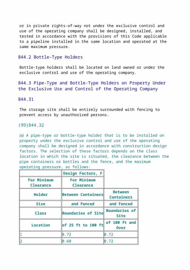
procedures(b) Emergency valve maintenance procedures include(1) written contingency plans to be followed during any type of emergency(2) training personnel to anticipate all potential hazards(3) furnishing tools and equipment as required, including auxiliary breathing equipment, to meet anticipated emergency valve servicing and/or maintenance requirements.
853.42 Distribution System Valves.
Valves, the use of which may be necessary for the safe operation of a gas distribution system, shall be checked and serviced, including lubrication where necessary, at sufficiently frequent intervals to ensure their satisfactory operation. Inspection shall include checking of alignment to permit use of a key or wrench and clearing from the valve box or vault any debris that would interfere with or delay the operation of the valve. System maps showing valve locations should be available.
853.43 Service Line Valves.
Outside shutoff valves installed in service lines supplying places of public assembly, such as theaters, churches, schools, and hospitals, shall be inspected and lubricated where required at sufficiently frequent intervals to ensure their satisfactory operation. The inspection shall determine if the valve is accessible, if the alignment is satisfactory, and if the valve box or vault, if used, contains debris that would interfere with or delay the operation of the valve. Unsatisfactory conditions encountered shall be corrected.
853.44 Valve Records.
A record shall be maintained for locating valves covered by paras. 853.41 and 853.42. These records may be maintained on operating maps, separate files, or summary sheets, and the information on these records shall be readily accessible to personnel required to respond to emergencies.
853.45 Prevention of Accidental Operation.
Precautions shall be taken to prevent accidental operation of any valve covered by paras. 853.41 and 853.42. Accidental valve operation by operating company personnel and the general public should be considered in taking these precautions. Some recommended actions to be taken, where applicable, are as follows:(a) Lock valves in aboveground settings readily accessible to the general public, that are not enclosed by a building or fence.(b) Lock valves located in vaults, if accessible to the general public.(c) Identify the valve by tagging, color coding, or any other suitable means of identification.
853.5 Vault Maintenance
Each vault housing a pressure limiting, pressure relief, or pressure regulating station shall be inspected to determine its condition each time the equipment is inspected and tested in accordance with para. 853.3. For any vault that personnel enter, the atmosphere shall be tested for combustible gas. If the atmosphere is hazardous, the cause shall be determined. The vault shall be inspected for
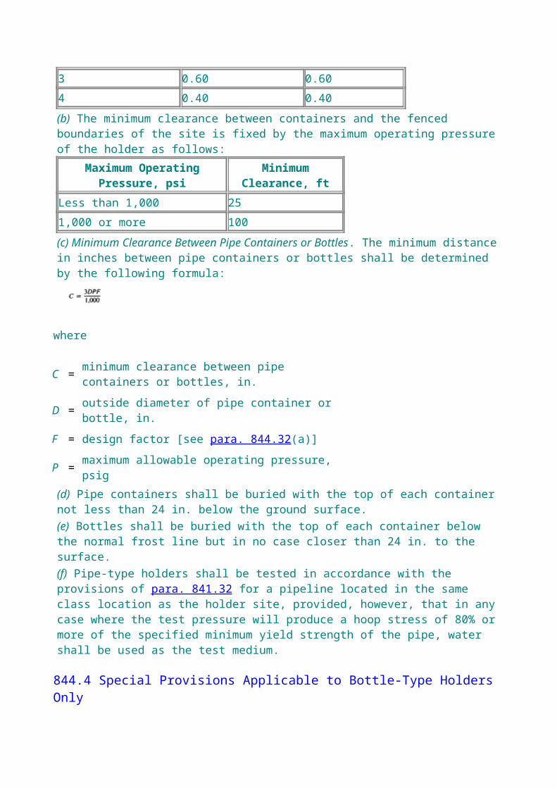
adequate ventilation. The condition of the vault covers shall be carefully examined for hazards. Unsatisfactory conditions disclosed shall be corrected. The applicable provisions of para. 821.6 shall be met before any welding is performed in the vault. Maintenance work performed in the vault shall be in accordance with procedures developed per para. 850.2(a), giving particular consideration to the monitoring of the atmosphere and safety protection for personnel in the vault.
854 LOCATION CLASS AND CHANGES IN NUMBER OF BUILDINGS INTENDED FOR HUMAN OCCUPANCY
854.1
(99) (a) Existing steel pipelines or mains operating in excess of 40% of specified minimum yield strength shall be monitored to determine if additional buildings intended for human occupancy have been constructed. The total number of buildings intended for human occupancy shall be counted to determine the current Location Class in accordance with the procedures specified in paras. 840.2(a) and (b).(b) In accordance with the principles stated in para. 840.1(c), and with the knowledge that the number of buildings intended for human occupancy is not an exact or absolute means of determining damage-causing activities, judgement must be used to determine the changes that should be made to items, such as operating stress levels, frequency of patrolling and cathodic protection requirements, as additional buildings intended for human occupancy are constructed.(99) (c) When there is an increase in the number of buildings intended for human occupancy to or near the upper limit of the Location Class listed in Table 854.1(c) to the extent that a change in Location Class is likely, a study shall be completed within 6 months of perception of the increase to determine the following:(1) the design, construction, and testing procedures followed in the original construction and a comparison of such procedures with the applicable provisions of this Code(2) the physical conditions of the pipeline or main to the extent that this can be ascertained from current tests and evaluation records(3) operating and maintenance history of the pipeline or main(4) the maximum operating pressure and the corresponding operating hoop stress. The pressure gradient may be taken into account in the section of the pipeline or main directly affected by the increasing number of buildings intended for human occupancy.(5) the actual area affected by the increase in the number of buildings intended for human occupancy and physical barriers or other factors that may limit the further expansion of the more densely populated area.(99) (d) Following this study, if a change of Location Class in indicated, the patrols and leakage surveys shall immediately be adjusted to the intervals established by the operating company for the new Location Class.
(99)854.2
If the study described in para. 854.1 indicates that the established maximum allowable operating pressure of a section of pipeline or main is not commensurate with existing Location Classes 2, 3, or 4, and such section is in satisfactory physical condition, the maximum allowable operating pressure of that section shall be confirmed or revised within 18 months following completion of the study as follows.(a) If the section involved has been previously tested in place for not less than 2 hr, the maximum

allowable operating pressure shall be confirmed or reduced so that it does not exceed that allowed in Table 854.1(c).(b) If the previous test pressure was not high enough to allow the pipeline to retain its MAOP or to achieve an acceptable lower MAOP in the Location Class according to subpara. (a) above, the pipeline may either retain its MAOP or become qualified for an acceptable lower MAOP if it is retested at a higher test pressure for not less than 2 hr in compliance with the applicable provisions of this Code. If the new strength test is not performed during the 18-month period following the Location Class change, the MAOP must be reduced so as to not exceed the design pressure commensurate with the requirements of Chapter IV at the end of the 18-month period. If the test is performed any time after the 18-month period has expired, however, the MAOP may be increased to the level it would have achieved if the test had been performed during that 18-month period.(c) An MAOP that has been confirmed or revised according to subparas. (a) or (b) above shall not exceed that established by this Code or previously established by applicable editions of the B31.8 Code. Confirmation or revision according to para. 854.2 shall not preclude the application of para. 845.6.(d) Where operating conditions require that the existing maximum allowable operating pressure be maintained, and the pipeline cannot be brought into compliance as provided in subparas. (a), (b), or (c) above, the pipe within the area of the Location Class change shall be replaced with pipe commensurate with the requirements of Chapter IV, using the design factor obtained from Table 841.114A for the appropriate Location Class.
854.3
Where the MAOP of a section of pipeline or main is revised in accordance with para. 854.2 and becomes less than the maximum allowable operating pressure of the pipeline or main of which it is a part, a suitable pressure relieving or pressure limiting device shall be installed in accordance with provisions of paras. 845.1, 845.2, and 845.212.
854.4
Where the study required in para. 854.1 indicates that the established maximum allowable operating pressure of a transmission pipeline is not commensurate with that permitted by this Code for the new location class, the sectionalizing valve spacing shall be reviewed and revised as follows:
(a) If the section of pipe is qualified for continued service because of a prior test, para. 854.2(a), or can be brought into compliance by lowering the maximum allowable operating pressure, para. 854.2(a), or testing, para. 854.2(b), no additional valves will normally be required.(b) Where a segment of pipeline must be replaced to maintain the established maximum allowable operating pressure as provided in para. 854.2(d), consideration should be given to valve spacing as follows:(1) Where a short section of line is replaced, additional valves will normally not be required.(2) Where the replacement section involves a mile or more of transmission line, additional valve installation shall be considered to conform to the spacing requirements in para. 846.11.
855 CONCENTRATIONS OF PEOPLE IN LOCATION CLASSES 1 AND 2
855.1
(99) (a) (1) Where a facility meeting the criteria of para. 840.3 is built near an existing steel pipeline in Location Classes 1 or 2, consideration shall be given to the possible consequence of a failure, even though the probability of such an occurrence is very unlikely if the line is designed, constructed, and operated in accordance with this Code. Where such a facility results in frequent concentrations of people, the requirements of (b) below shall apply.(2) However, (b) below need not be applied if the facility is used infrequently. The lesser usage combined with the very remote possibility of a failure at that particular point on the pipeline virtually eliminates the possibility of an occurrence.(b) Pipelines near places of public assembly as outlined in (a) above shall have a maximum allowable hoop stress not exceeding 50% of SMYS. Alternatively, the operating company may make the study described in para. 854.1(c) and determine that compliance with the following will result in an adequate level of safety:(1) The segment is hydrostatically retested for at least 2 hr to a minimum stress level of(a) 100% of SMYS if the pipeline is operating over 60% and up to 72% of SMYS(b) 90% of SMYS if the pipeline is operating over 50% and up to 60% of SMYS, unless the segment was tested previously to a pressure of at least 1.5 times the MAOP.If the segment contains pipe of various operating stress levels, the minimum test stress levels stated above should be based on the SMYS of the pipe with the highest operating stress level.(2) Patrols and leakage surveys are conducted at intervals consistent with those established by the operating company for Location Class 3.(3) When the maximum allowable hoop stress exceeds 60% of SMYS, adequate periodic visual inspections are conducted by an appropriate sampling technique, or instrumented inspections capable of detecting gouges and corrosion damage are made to confirm the continuing satisfactory physical condition of the pipe.(4) If the nearby facility is likely to encourage additional construction activity, provide appropriate pipeline markers.
856 PIPELINE SERVICE CONVERSIONS
856.1 General
The intent of this section is to provide requirements to allow an operator of a steel pipeline previously used for service not covered by this Code to qualify that pipeline for service under this Code. For a dual service pipeline used alternately to transport liquids in conformance with an
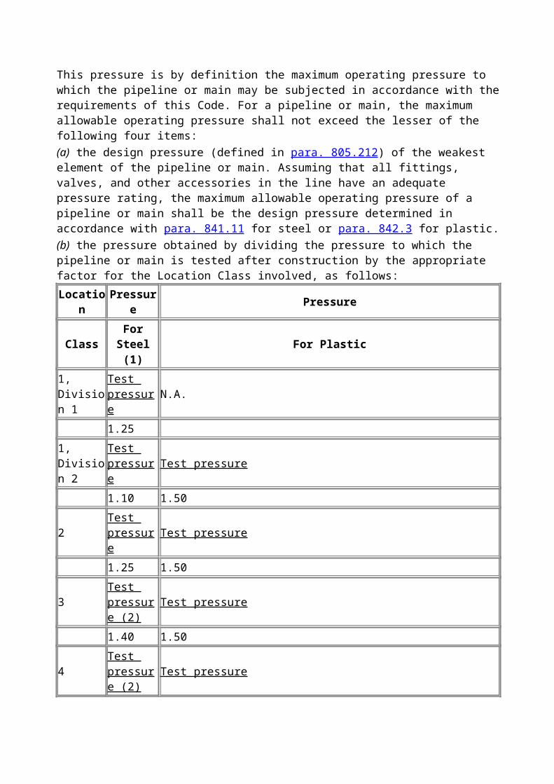
appropriate Code, such as ASME B31.4, and gas under this Code, only the initial conversion to gas service requires qualification testing.
856.2 Historical Records Study
Review the following historical data and make an evaluation of the pipeline's condition.(a) Study all available information on the original pipeline design, inspection, and testing. Particular attention should be paid to welding procedures used and other joining methods, internal and external coating, pipe, and other material descriptions.(b) Study available operating and maintenance data including leak records, inspections, failures, cathodic protection, and internal corrosion control practices.(c) Consider the age of the pipeline and the length of time it may have been out of service in preparing a final evaluation to convert the pipeline to gas service.
856.3 Requirements for Conversion to Gas Service
A steel pipeline previously used for service not subject to this Code may be qualified for service under this Code as follows:(a) Review historical records of the pipeline as indicated in para. 856.2.(b) Inspect all above-ground segments of the pipeline for physical condition. During the inspection, identify the material where possible for comparison with available records.(c) Operating Stress Level Study(99) (1) Establish the number of buildings near the pipeline or main intended for human occupancy, and determine the design factor for each segment in accordance with para. 840.2 and Table 841.114A.(2) Conduct a study to compare the proposed operating stress levels with those allowed for the Location Class.(99) (3) Replace facilities necessary to make sure the operating stress level is commensurate with the Location Class.(d) If necessary, make inspections of appropriate sections of underground piping to determine the condition of the pipeline.(e) Make replacements, repairs, or alterations that in the operating company's judgement are advisable.(f) Perform a strength test in accordance with this Code to establish the maximum allowable operating pressure of the pipeline, unless the pipeline has been so tested previously.(g) Perform a leak test in conformance with this Code.(h) Within 1 year of the date that the converted pipeline is placed in gas service, provide cathodic protection as set out in para. 862.2, except that wherever feasible, replacement sections and other new piping shall be cathodically protected as required for new pipelines.
856.4 Conversion Procedure
Prepare a written procedure outlining the steps to be followed during the study and conversion of the pipeline system. Note any unusual conditions relating to this conversion.
856.5 Records of the Conversion
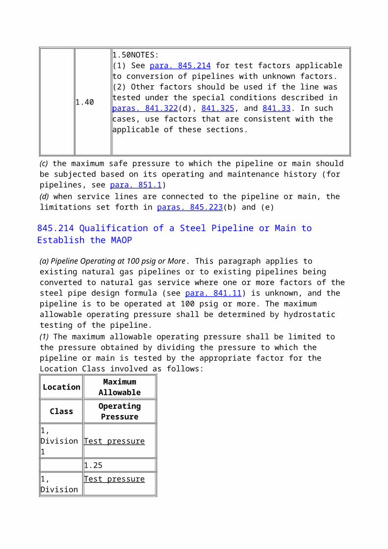
Maintain for the life of the pipeline a record of the studies, inspections, tests, repairs, replacements, and alterations made in connection with conversion of the existing steel pipeline to gas service under this Code.
CHAPTER VI CORROSION CONTROL
860 CORROSION CONTROL
861 SCOPE
(a) This Chapter contains the minimum requirements and procedures for corrosion control of exposed, buried, and submerged metallic piping and components. (See Chapter VIII for special offshore requirements.) This Chapter contains minimum requirements and procedures for controlling external (including atmospheric) and internal corrosion. This Chapter is applicable to the design and installation of new piping systems and to the operation and maintenance of existing piping systems.(b) The provisions of this Chapter should be applied under the direction of competent corrosion personnel. Every specific situation cannot be anticipated; therefore, the application and evaluation of corrosion control practices require a significant amount of competent judgment to be effective in mitigating corrosion.(c) Deviations from the provisions of this Chapter are permissible in specific situations, provided the operating company can demonstrate that the objectives expressed herein have been achieved.(d) Corrosion control requirements and procedures may, in many instances, require measures in addition to those shown in this Chapter. Each operating company shall establish procedures to implement its corrosion control program, including the requirements of this Chapter, to achieve the desired objectives. Procedures, including those for design, installation, and maintenance of cathodic protection systems, shall be prepared and implemented by, or under the direction of, persons qualified by training and/or experience in corrosion control methods.
862 EXTERNAL CORROSION CONTROL
862.1 New Installations
862.11 Buried Steel Facilities
862.111 General.
All new transmission pipelines, compressor station piping, distribution mains, service lines, and pipe-type and bottle-type holders installed under this Code shall, except as permitted under para. 862.113, be externally coated and cathodically protected unless it can be demonstrated by test or experience that the materials are resistant to corrosion in the environment in which they are installed. Consideration shall be given to the handling, shipping, storing, installation conditions, and the service environment and cathodic protection requirements when selecting the coating materials. The Corrosion Data Survey, published by the National Association of Corrosion Engineers (NACE), is a source of information on materials performance in corrosive environments.
862.112 Coating Requirements
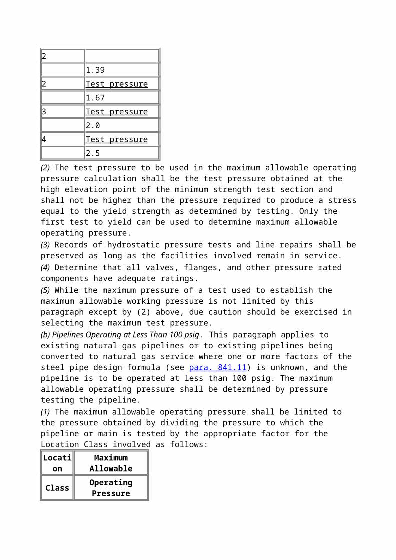
(a) The surface preparation should be compatible with the coating to be applied. The pipe surface shall be free of deleterious materials, such as rust, scale, moisture, dirt, oils, lacquers, and varnish. The surface shall be inspected for irregularities that could protrude through the coating. Any such irregularities shall be removed. Further information can be obtained from NACE RP-02-75.(b) Suitable coatings, including compatible field joint and patch coatings, shall be selected, giving consideration to handling, shipping, storing, installation condition, moisture adsorption, operating temperatures of the pipeline, environmental factors (including the nature of the soil in contact with the coating), adhesion characteristics, and dielectric strength.(c) Coating shall be applied in a manner that ensures effective adhesion to the pipe. Voids, wrinkles, holidays, and gas entrapment should be avoided.(d) The coating shall be visually inspected for defects before the pipe is lowered into the ditch. Insulating type coatings on mains and transmission lines shall be inspected for holidays by the most appropriate method. Coating defects or damage that may impair effective corrosion control shall be repaired before the pipe is installed in the ditch.(e) In addition to the provisions of paras. 841.222, 841.252, and 841.253, care shall be exercised in handling, storage, and installation to prevent damage to the coating, including measures noted as follows. (1) Minimize handling of coated pipe. Use equipment least likely to damage the coating, e.g., belts or cradles instead of cables.(2) Use padded skids where appropriate.(3) Stack or store pipe in a manner that minimizes damage to coating.
862.113 Cathodic Protection Requirements.
Unless it can be demonstrated by tests or experience that cathodic protection is not needed, all buried or submerged facilities with insulating type coatings, except facilities installed for a limited service life, shall be cathodically protected as soon as feasible following installation. Minor replacements or extensions, however, shall be protected as covered by para. 862.212.Facilities installed for a limited service life need not be cathodically protected if it can be demonstrated that the facility will not experience corrosion that will cause it to be harmful to the public or environment. Cathodic protection systems shall be designed to protect the buried or submerged system in its entirety. A facility is considered to be cathodically protected when it meets one or more of the criteria established in Appendix K.
862.114 Electrical Isolation
(a) All coated transmission and distribution systems shall be electrically isolated at all interconnections with foreign systems including customer's fuel lines, except where underground metallic structures are electrically interconnected and cathodically protected as a unit. Steel pipelines shall be electrically isolated from cast iron, ductile iron, or nonferrous metal pipelines and components. Electrical tests shall be made of transmission and distribution systems to locate unintentional contacts with other metallic structures. If such contacts exist, they shall be corrected. See para. 841.143 for clearance requirements.(b) Where a gas pipeline parallels overhead electric transmission lines, consideration shall be given to(1) investigating the necessity of protecting insulating joints in the pipeline against induced voltages resulting from ground faults and lightning. Such protection can be obtained by connecting buried galvanic anodes to the pipe near the insulating joints and/or by bridging the pipeline
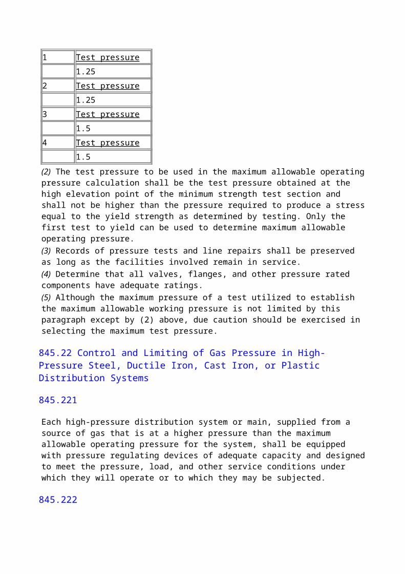
insulator with a spark gap, or by other effective means(2) making a study in collaboration with the electric company, taking the following factors into consideration and applying remedial measures as appropriate:(a) the need to mitigate induced AC voltages or their effects on personnel safety during construction and operation of the pipeline by means of suitable design for bonding, shielding, or grounding techniques(b) the possibility of lightning or fault currents inducing voltages sufficient to puncture pipe coatings or pipe(c) possible adverse effects on cathodic protection, communications, or other electronic facilities(d) the corrosive effects of high voltage direct current (HVDC) power systems(3) obtaining further information from NACE RP-01-77 and EPRI EL-3106
862.115 Electrical Connections and Monitoring Points
(a) Except for offshore pipelines, sufficient test points should be installed to demonstrate the effectiveness of corrosion control or the need for cathodic protection. (See Chapter VIII for special considerations for offshore pipelines.)(b) Special attention shall be given to the manner of installation of electrical leads used for corrosion control or testing to avoid harmful stress concentration at the point of attachment to the pipe. Acceptable methods include, but are not limited to(1) electrical leads attached directly on the pipe or by the thermit welding process, using copper oxide and aluminum powder. The size of the thermit welding charge shall not exceed a 15-g cartridge.(2) attachment of electrical leads directly to the pipe by the use of soft solders or other materials that do not involve temperatures exceeding those for soft solders(c) All pipe that is barred for electrical lead connections and all bared electrical lead wires shall be protected by electrical insulating material compatible with existing coating.
862.116 Electrical Interference
(a) Impressed current cathodic protection systems shall be designed, installed, and operated so as to minimize adverse effects on existing metallic structures.(b) Field tests shall be conducted to determine the adverse electrical interference from foreign structures, including DC electrical facilities. The effects shall be mitigated by such means as control bonds, supplementary cathodic protection, protective coatings, and insulating devices.
862.117 Casings.
The use of metallic casings should be avoided as much as as possible from a corrosion control standpoint. It is recognized, however, that installation of metallic casings is frequently required or desirable to facilitate construction, as an economical method of protecting existing pipelines, to provide structural protection from heavy and/or impact loads to facilitate replacement as required by a governmental agency and as required by the landowner or permit grantor, and for other reasons. Where metallic casing is used, care should be exercised to ensure that coating on the carrier pipe is not damaged during installation. The carrier pipe should be insulated from metallic casings, and the casing ends should be sealed with a durable material to minimize the accumulation of solids and liquids in the annular space. Special attention should be given to the casing ends to prevent electrical shorting due to backfilling movement or settling. Where electrical isolation is not
achieved, action shall be taken to correct the condition or mitigate corrosion inside of the casing by supplemental or localized cathodic protection, installation of a high-resistivity inhibited material in the annular space, or other effective means.
862.12 Atmospheric Protection
(a) Facilities exposed to the atmosphere shall be protected from external corrosion by a suitable coating or jacket.(b) The surface to be coated shall be free of deleterious materials, such as rust, scale, moisture, dirt, oil, lacquer, and varnish. The surface preparation shall be compatible with the coating or jacket to be applied.(c) The coating or jacket selected shall possess characteristics that will provide adequate protection from the environment. Coatings and jackets shall completely cover the exposed structure and shall be applied in accordance with established specifications or manufacturer's recommendations.(d) Special consideration shall be given to surfaces near the ground line or in a splash zone.
862.13 Other Materials.
Where investigation or experience indicates that the environment in which the pipe or component is to be installed is substantially corrosive, the following shall be considered:(a) materials and/or component geometry shall be designed to resist detrimental corrosion(b) a suitable coating(c) cathodic protection
(99)862.2 Existing Installations
Procedures shall be established for evaluating the need for and effectiveness of a corrosion control program. Appropriate corrective action commensurate with the conditions found shall be taken. The procedures and actions should include, but should not be limited to, the items in paras. 862.21 through 862.25.
862.21 Buried Steel Facilities
862.211 Evaluation
(a) The records available as a result of leakage surveys and normal maintenance work in accordance with paras. 852.2 and 852.6 shall be continuously reviewed for evidence of continuing corrosion.(b) Electrical survey methods may be used as an indication of suspected corrosive areas where surface conditions permit sufficiently accurate measurements. Such surveys are most effective in nonurban environments. Common methods of electrical survey include
(1) pipe-to-soil potentials
(2) surface potentials (cell-to-cell)
(3) soil resistivity measurements
(c) The continued effectiveness of a cathodic protection system shall be monitored in accordance with para. 862.217.
862.212 Corrective Measures
(a) If continuing corrosion that, unless controlled, could result in a condition that is detrimental to public or employee safety is found by the evaluation made under para. 862.211 or 862.217(d), appropriate corrective measures shall be taken to mitigate further corrosion on the piping system or segment. Corrective measures shall be continued in effect as long as required to maintain a safe operating system. Appropriate corrective measures may include the following:(1) provisions for proper and continuous operation of cathodic protection facilities(2) application of protective coating(3) installation of galvanic anode(s)(4) application of impressed current(5) electrical isolation(6) stray current control(7) other effective measures(8) any combination of the above(b) When experience or testing indicates the above mitigation methods will not control continuing corrosion to an acceptable level, the segment shall be reconditioned or replaced and suitably protected.
862.213 Repair of Corroded Pipe.
If the extent of corrosion has reduced the strength of a facility below its maximum allowable operating pressure, that portion shall be repaired, reconditioned, or replaced, or the operating pressure shall be reduced, commensurate with the remaining strength of the corroded pipe. For steel pipelines operating at or above 40% of the specified minimum yield strength, the remaining strength of corroded pipe may be determined in accordance with Appendix L. For background information on Appendix L, refer to ANSI/ASME B31G, titled Manual for Determining the Remaining Strength of Corroded Pipelines.
862.214 Cathodic Protection Criteria
(a) A facility is considered to be cathodically protected when it meets one or more of the criteria established in Appendix K.(b) It is not intended that cathodic protection be limited to these criteria if it can be demonstrated by other means that adequate control of corrosion has been achieved.
862.215 Electrical Interference
(a) Adverse electrical interference from or to foreign structures as determined by field tests shall be mitigated.(b) Facilities for mitigating electrical interference shall be periodically monitored.
862.216 Examination When Exposed
(a) Whenever a buried facility is exposed during normal maintenance or construction activities, a visual inspection shall be made of the coating condition and/or the metal surface, if exposed.(b) The extent of any corrosion shall be evaluated in accordance with para. 862.213.
862.217 Operation and Maintenance of Cathodic Protection System
(a) Inspections shall be made as required to maintain continuous and effective operation of the cathodic protection system.(b) Electrical tests shall be made periodically to determine that the piping system is protected in accordance with the applicable criteria.(c) The type, frequency, and location of inspections and tests shall be adequate to establish with reasonable accuracy the degree of protection provided on the piping system. Frequency should be determined by consideration of items including, but not limited to, the following:(1) condition of pipe(2) method of cathodic protection(3) corrosiveness of the environment(4) probability of loss or interruption of protection(5) operating experience, including inspections and leak investigations(6) design life of the cathodic protection installation(7) public or employee safety(d) Where the tests or surveys indicate that adequate protection does not exist, appropriate corrective measure shall be taken.
862.218 Casings.
Electrical isolation of cathodically protected pipelines and mains from metallic casings that are part of the underground system shall be maintained as necessary to ensure effectiveness of cathodic protection. Electrical measurements and inspections shall be made as necessary to provide timely evidence of shorts that would adversely affect cathodic protection. If there is evidence of shorts between the carrier pipe and casing that renders cathodic protection of the pipeline or main ineffective, or if evidence of corrosion of the carrier pipe inside the casing is found, remedial measures shall be taken as necessary to correct the condition or minimize corrosion inside the casing.
862.22 Buried Cast Iron, Wrought Iron, and Ductile Iron
862.221 Evaluation.
The records available as a result of leakage surveys and normal maintenance work in accordance with paras. 852.2 and 852.6 shall be routinely reviewed to determine pipe conditions. Appropriate corrective measures shall be taken in accordance with para. 862.222 if such review reveals that a condition that may affect public and employee safety exists. Pipe size, operating pressure, terrain, recent underground construction; proximity and number of other underground facilities and buildings; and pipe condition shall be considered in determining the presence of such a condition.
862.222 Corrective Measures.
The magnitude of the problem will dictate the corrective measures that shall be considered. They may include, but are not limited to
(a) pipe repair
(b) pipe replacement
(c) pipe reinforcement and/or support
(d) pressure reduction
862.223 Installation of Electrical Connections
(a) Electrical connections may be attached directly onto the cast or ductile iron pipe by the thermit welding process using copper oxide and aluminum powder. The size of the thermit welding charge shall not exceed a 32-g cartridge.(b) All pipe that is bared for test lead connections and all bared test lead wires shall be protected by electrical insulating material compatible with the existing coating.
862.224 Electrical Interference
(a) If an impressed current type cathodic protection system is used, the anodes shall be located so as to mitigate adverse effects on existing underground metallic structures.(b) Adverse electrical interference from foreign structures as determined by field tests shall be mitigated.
862.23 Requirements for Cast Iron and Ductile Iron Piping Facilities Exposed to Atmosphere.
Aboveground cast iron and ductile iron pipe shall be suitably protected in areas where severe atmospheric corrosion may occur.
862.24 Other Metallic Materials.
When a nonferrous metal or ferrous alloy component is found to have corroded to the point where public or employee safety may be affected, it shall be reconditioned in accordance with para. 862.13 or replaced. The replacement shall meet one of the following criteria:(a) it shall be constructed with other materials and/or geometry designed for the remaining life of the parent facility(b) it shall be cathodically or otherwise protected.
862.25 Atmospheric Corrosion.
Facilities exposed to the atmosphere shall be periodically inspected for indication of surface corrosion. Where corrosion is taking place to the extent that public or employee safety may be affected, the facility shall be reconditioned in accordance with para. 862.12 or replaced. Special consideration shall be given to surfaces near the ground line.
863 INTERNAL CORROSION CONTROL
863.1 General
When corrosive gas is transported, provisions shall be taken to protect the piping system from detrimental corrosion. Gas containing free water under the conditions at which it will be transported shall be assumed to be corrosive, unless proven to be noncorrosive by recognized tests or experience.
863.2 New Installations
When designing a new or replacement pipeline system, or additions or modifications to existing systems, measures shall be considered to prevent and/or inhibit internal corrosion. To preserve the integrity and efficiency of a pipeline in which it is known or anticipated that corrosive gas will be transported, the following factors should be included in the design and construction, either separately or in combination.(a) When internal coating is to be used to protect a piping system(1) the coating shall meet the quality specifications, and the minimum dry film thickness shall be established to protect the facility from the corrosive media involved, based on the type of coating and methods of application(2) applied coatings shall be inspected in accordance with established specifications or accepted practice(3) provision shall be made to prevent joint corrosion, such as cleaning and recoating or the continuing use of a suitable inhibitor when coated pipe or other components are joined by welding or other methods that leave the parent metal exposed(4) the types of coating and pitting tools used should be evaluated and chosen to prevent damage to the internal coating if pigs or spheres are to be used(b) When a corrosion inhibitor is to be used as an additive to the gas streams(1) the equipment for the holding, transfer, and injection of the inhibitor into the stream shall be included in the design(2) the operation of the injection program should be a part of the planning(3) sufficient test coupon holders or other monitoring equipment shall be provided to allow for continued program evaluations(4) the corrosion inhibitor selected shall be of a type that will not cause deterioration of any components of the piping system(c) When a pipeline pigging system is planned:(1) scraper traps for the insertion and removal of pigs and/or spheres shall be provided(2) sections of pipeline to be traversed by pigs or spheres shall be designed to prevent damage to pigs, spheres, pipes, or fittings during operations(3) piping for pigs or spheres shall be designed to guide the tool and the materials they propel effectively and safely(4) provisions shall be made for effective accumulation and handling of liquid and solid materials removed from the pipeline by pigs or spheres(d) When corrosion coupons, corrosion probes, and/or test spools are to be used(1) corrosion coupons, probes, or test spools shall be installed where practical at locations where the greatest potential for internal corrosion exists(2) corrosion coupons, probes, and test spools must be designed to permit passage of pigs or
spheres when installed in sections traversed thereby(e) When gas is to be treated to reduce its corosivity(1) separators and/or dehydration equipment may be installed(2) equipment for the removal of other deleterious material from the gas should be considered.(f) The material of the pipe and other equipment exposed to the gas stream must resist internal corrosion; therefore,(1) materials selected for pipe and fittings shall be compatible with the components of the gas, the liquids carried by the gas, and with each other. A source of information on materials performance in corrosive environments is The Corrosion Data Survey, published by NACE.(2) where plastic, nonferrous, or alloy steel pipe and components are used to prevent or control internal corrosion, such materials shall have been determined to be effective under the conditions encountered. [See paras. 842.611(b) and 849.611(b) for limitations on copper.](3) erosion-corrosion effects from high-velocity particles at probable points of turbulence and impingement should be minimized by use of erosion-resistant materials, added wall thickness, design or flow configuration, and size or dimensions of the pipe and fittings.
863.3 Existing Installations
A pipeline internal corrosion control program shall include, but shall not be limited to, the following:(a) The establishment and evaluation of a program for the detection, prevention, or mitigation of detrimental internal corrosion should include the following:(1) Pipeline leak and repair records should be reviewed for indication of the effects of internal corrosion.(2) When any part of a pipeline is removed and the internal surface is accessible for inspection, it should be visually examined and evaluated for internal corrosion.(3) If evidence of internal corrosion is discovered, the gas shall be analyzed to determine the types and concentrations of any corrosive agents.(4) Liquids or solids removed from the pipeline by pigging, draining, or cleanup should be analyzed as necessary to determine the presence of corrosive materials and evidence of corrosion products.(b) Where it is determined that internal corrosion taking place could affect public or employee safety, one or more of the following protective or corrective measures shall be used to control detrimental internal corrosion:(1) An effective corrosion inhibitor shall be applied in a manner and quantity to protect all affected portions of the piping systems.(2) Corrosive agents shall be removed by recognized methods, such as acid gas or dehydration treating plants.(3) Fittings shall be added for removal of water from low spots, or piping shall be positioned to reduce sump capacities.(4) Under some circumstances, application of a suitable internal coating may be effective.(c) Internal corrosion control measures shall be evaluated by an inspection and monitoring program, including, but not limited to, the following.(1) The inhibitor and the inhibitor injection system should be periodically checked.(2) Corrosion coupons and test spools shall be removed and evaluated at periodic intervals.(3) Corrosion probes should be checked manually at intervals, or continuously or intermittently monitored and/or recorded to evaluate control of pipeline internal corrosion,
(4) A record of the internal condition of the pipe, of leaks and repairs from corrosion, and of gas, liquids, or solids quantities and corrosivity should be kept and used as a basis for changes in the pigging schedule, inhibitor program, or gas treatment facility.(5) When pipe is uncovered, or on exposed piping where internal corrosion may be anticipated, pipe wall thickness measurement or monitoring will help evaluate internal corrosion.(6) Where inspections, observation, or record analysis indicates internal corrosion is taking place to an extent that may be detrimental to public or employee safety, that portion of the system shall be repaired or reconditioned, and appropriate steps shall be taken to mitigate the internal corrosion.
864 PIPELINES IN ARCTIC ENVIRONMENTS
864.1 General
Special consideration must be given to the corrosion control requirements of buried pipelines and other facilities installed in arctic environments, particularly in permafrost regions. For pipelines in contact with frozen earth, the corrosion rate is reduced because of the extremely high resistivity of the soil and low ion mobility, but it does not reach zero. Significant corrosion can occur, however, in unfrozen inclusions, discontinuous permafrost, or thaw areas such as those that may occur in the vicinity of rivers, lakes, springs, or pipeline sections where the pipe surface temperature is above the freezing point of the environment. Cathodic protection in localized thaw areas may be more difficult due to the shielding of cathodic protection currents by the surrounding frozen soil. Other detrimental effects can be caused by seasonal thaws that increase biological and bacteriologic activity in the nonpermafrost areas or in the "active layer" above underlying permafrost.Pipeline facilities installed in arctic environments shall be coated and cathodically protected in the same manner as pipelines in temperate locations, and the same consideration shall be given to the need for protection from internal and atmospheric corrosion, except as specifically provided in this section.
864.2 External Coating Requirements
Coatings for pipelines in low-temperature environments shall be selected according to the particular requirements of that environment. These include adhesion, resistance to cracking or damage during handling and installation in subfreezing temperatures, applicability of field joint coatings or coating repairs, compatibility with any applied cathodic protection, and resistance to soil stresses due to frost heave, seasonal temperature changes, or other reasons.
864.3 Cathodic Protection Facilities
864.31 Criteria.
Criteria for cathodic protection shall be the same as those for pipelines in temperate environments. Because higher driving voltages are normally required in frozen soils, the voltage impressed across the coating should be limited so that the coating is not subject to damage due to cathodic overvoltage or excessive current density.
864.32 Impressed Current Facilities
(a) Impressed current facilities shall be used on pipelines in permanently frozen soil, especially where the gas is chilled to prevent thawing of the earth. Such facilities are capable of providing the higher driving voltage needed to overcome the high resistivity of frozen soil. They can be installed at compressor stations or other facilities where power is available and access for adjustment and maintenance is ensured. The effects of seasonal variations in soil resistivity should be compensated for by using constant potential rectifiers or manual adjustments.(b) Impressed current anode beds shall be installed whenever feasible at a sufficient distance from the pipeline or other underground structures to achieve maximum spread along the pipeline and to reduce the peak potential at the pipeline.(c) Anode beds shall be installed, where practical, below the permafrost level or in other unfrozen locations, such as a stream or lake, to achieve better cathodic current distribution. Where anodes must be installed in permanently frozen ground, the volume of the anode backfill material should be increased to reduce the effective resistance between the anode and the surrounding earth.(d) Impressed current facilities using distributed or deep anode ground beds should be used to protect buried station facilities and pilings where used to support aboveground plant facilities. The pilings and any other adjacent underground metallic facilities must be electrically interconnected to prevent detrimental interference.
864.33 Galvanic Anode Installations.
Galvanic anodes (packaged or ribbon) may be needed on pipelines in permafrost areas to supplement impressed current facilities in localized thawed areas. This provides localized cathodic protection to those sections of pipe that might be shielded by the extremely high resistivity of the surrounding soil.
864.4 Monitoring
Installation of calibrated current measurement spans should be considered in addition to the normal test points. These should be installed at sufficient intervals to evaluate current distribution along the protected pipeline and the effects of telluric currents prevalent in polar regions. These spans also provide contact points for measuring indications of possible coating damage due to stresses induced by a frozen environment.
864.5 Internal Corrosion Control
Where the gas stream is chilled to prevent melting of frozen soil surrounding the pipeline, there will not normally be enough free water in the gas to result in internal corrosion in the presence of contaminants, such as sulfur compounds or CO2. If it is anticipated, however, that free water or water/alcohol solutions will be present in the pipeline along with potentially corrosive contaminants, suitable corrective measures shall be taken as prescribed in para. 863.
865 PIPELINES IN HIGH TEMPERATURE SERVICE
865.1 General
Special consideration must be given to the corrosion control requirements of pipelines and other facilities in high-temperature service (above 150°F). Elevated temperatures tend to decrease the resistivity of buried or submerged pipeline environments and to increase the electrochemical
corrosion reaction as a result of accelerated ionic or molecular activity. Elevated temperatures typically occur downstream of compressor stations or in gathering systems.
865.2 External Coating Requirements
Coatings shall be selected based on the particular requirements for pipeline facilities in high temperature service. These include resistance to damage from soil or secondary stresses, compatibility with any applied cathodic protection, and particularly, resistance to thermal degradation. In rocky environments, the use of a protective outer wrap, select backfill, or other suitable measures shall be considered to minimize physical damage.
865.3 Cathodic Protection Facilities
865.31 Criteria.
Criteria for cathodic protection shall be the same as those for normal temperature service, except that recognition should be given to the effects of decreased resistivity and increased cathodic protection current requirements in elevated temperature service on any IR component of the pipe-to-soil potential measurement. Possible depolarization effects due to high temperature operation shall also be considered.
865.32 Galvanic Anodes.
Consideration shall be given to the impact on the performance of close galvanic anodes (especially bracelet or ribbon type) subject to elevated temperatures due to their proximity to a hot pipeline. Higher temperatures tend to increase the current output and rate of degradation of most anode materials. Some anode materials may become more noble than steel at temperatures above 140°F in certain electrolytes. Zinc anodes containing aluminum are also susceptible to intergranular corrosion above 120°F.
865.4 Internal Corrosion Control
When gas or a mixture of gas and liquids or solids known or anticipated to be corrosive is transported at elevated temperatures, special consideration shall be given to the identification and mitigation of possible internal corrosion. Such measures are necessary because corrosion reaction rates increase with elevated temperatures and are not stable. Appropriate mitigation and monitoring measures are given in para. 863.
866 STRESS CORROSION AND OTHER PHENOMENA
Environmentally induced and other corrosion-related phenomena, including stress corrosion cracking, corrosion fatigue, hydrogen stress cracking, and hydrogen embrittlement have been identified as causes of pipeline failure. Considerable knowledge and data have been acquired and assembled on these phenomena, and research is continuing as to their causes and prevention. Operating companies should be alert for evidence of such phenomena during all pipe inspections and at other such opportunities. Where evidence of such a condition is found, an investigative program shall be initiated, and remedial measures shall be taken as necessary. Any such evidence
should be given consideration in all pipeline failure investigations. Operating companies should avail themselves of current technology on the subject and/or consult with knowledgeable experts.This paragraph must be limited to general statements rather than specific limits in regard to stress corrosion. Stress corrosion is currently the subject of investigative research programs, and more specific data will certainly be available to the pipeline designer and operating company in the future. In the interim, this Code suggests that the user refer to the current state of the art. Cathodic protection current levels, quality of pipe surface preparation and coating, operating temperatures, stress levels, and soil conditions shall be considered in pipeline design and operations.
867 RECORDS
(a) Records indicating cathodically protected piping, cathodic protection facilities, and other structures affected by or affecting the cathodic protection system shall be maintained by the operating company.(b) Records of tests, surveys, inspection results, leaks, etc., necessary for evaluating the effectiveness of corrosion control measures, shall be maintained and retained for as long as the piping remains in service.
CHAPTER VII MISCELLANEOUS
870 MISCELLANEOUS
871 ODORIZATION
871.1
Any gas distributed to customers through gas mains or service lines or used for domestic purposes in compressor plants, which does not naturally possess a distinctive odor to the extent that its presence in the atmosphere is readily detectable at all gas concentrations of one-fifth of the lower explosive limit and above, shall have an odorant added to it to make it so detectable.
871.11
Odorization is not required for(a) gas in underground or other storage(b) gas used for further processing or use where the odorant would serve no useful purpose as a warning agent or would be a detriment to the process(c) gas used in lease or field operations
871.12
If gas is delivered for use primarily in one of the above exempted activities or facilities and is also used in one of those activities for space heating, refrigeration, water heating, cooking, and other domestic uses, or if such gas is used for furnishing heat or air conditioning for office or living quarters, the gas shall be odorized.
871.2
Each operating company shall use odorization equipment designed for the type and injection rate of odorant being used.
871.3
Each operating company shall use an odorant in accordance with the following requirements:(a) The odorant, when blended with gas in the specified amount, shall not be deleterious to humans or to the materials present in the gas system and shall not be soluble in water to a greater extent than 2 parts of odorant to 100 parts of water by weight.(b) The products of combustion from the odorant shall be nontoxic to humans breathing air containing the products of combustion and shall not be corrosive or harmful to the materials with which such products of combustion would ordinarily come in contact.(c) The combination of the odorant and the natural odor of the gas shall provide a distinctive odor so that when gas is present in air at the concentration of as little as 1% by volume, the odor is readily detectable by a person with a normal sense of smell.
871.4
For all odorizers, except small wick-type or bypass-type, or similar odorizers serving individual customers or small distribution systems, each operating company shall maintain records containing the following items(a) the type of odorant introduced into the gas(b) the amount of odorant injected per million cubic feet
871.5
Each operating company shall conduct odorant concentration tests on gas supplied through its facilities that requires odorization. Test points shall be remotely located from the odorizing equipment to provide data representative of gas at all points of the system.
872 LIQUEFIED PETROLEUM GAS (LPG) SYSTEMS
872.1
Liquefied petroleum gases generally include butane, propane, and mixtures of the two that can be stored as liquids under moderate pressures (approximately 80 psig to 250 psig) at ambient temperatures.
872.2
This Code is concerned only with certain safety aspects of liquefied petroleum gases when they are vaporized and used as gaseous fuels.
872.3
All of the requirements of ANSI/NFPA 58 and ANSI/NFPA 59 and of this Code concerning design, construction, and operation and maintenance of piping facilities shall apply to piping systems handling butane, propane, or mixtures of these gases.
872.4 Special Safety Requirements for LPG Systems
872.41 Odorization.
Liquefied petroleum gases are usually nontoxic, but when distributed for consumer use or used as fuel in a place of employment, they shall be odorized for safety. Criteria for odorization are given in section 871.8
872.42 Ventilation
(a) All liquefied petroleum gases are heavier than air; hence, structures aboveground for housing regulators, meters, etc., shall have open vents near the floor level. Such equipment shall not be installed in pits or in underground vaults, except in cases where suitable provisions for forced ventilation are made.(b) Special care is required in the location of relief valve discharge vents releasing LPG to the atmosphere to prevent accumulation of the heavy gases at or below ground level. Likewise, special precautions are necessary for adequate ventilation where excavations are made for the repair of leaks in an underground LPG distribution system.
873 PIPELINES ON PRIVATE RIGHTS-OF-WAY OF ELECTRIC TRANSMISSION LINES
Where gas pipelines parallel overhead electric transmission lines on the same right-of-way, the company operating the pipelines shall take the following precautions:
873.1
Employ blowdown connections that will direct the gas away from the electric conductors.
(99)873.2
Install a bonding conductor across points where the main is to be separated and maintain this connection while the pipeline is separated. The current carrying capacity of the bonding conductor should be at least one-half of the current carrying capacity of the overhead line conductors. [See also para. 862.114(b).]
CHAPTER VIII OFFSHORE GAS TRANSMISSION
A800 OFFSHORE GAS TRANSMISSION
(99)A801 GENERAL
Chapter VIII pertains only to offshore gas transmission systems as defined in para. A802.1. With the exception of sections A840 through A842, A844, and A847, this Chapter is organized to parallel the numbering and the content of the first six chapters of the Code. All provisions of the first six chapters of the Code are also requirements of this Chapter unless specifically modified herein. Chapter VII is not applicable. With the exceptions noted above, paragraph designations follow those in the first six chapters with the prefix "A."
A802 SCOPE AND INTENT
A802.1 Scope
This Chapter of the Code covers the design, material requirements, fabrication, installation, inspection, testing, and safety aspects of operation and maintenance of offshore gas transmission systems. For this Chapter, offshore gas transmission systems include offshore gas pipelines, pipeline risers, offshore gas compressor stations, pipeline appurtenances, pipe supports, connectors, and other components as addressed specifically in the Code.
A802.2 Intent
The intent of this Chapter is to provide adequate requirements for the safe and reliable design, installation, and operation of offshore gas transmission systems. Requirements of this Chapter supplement the requirements of the remainder of the Code. It is therefore not the intent of this Chapter to be all inclusive, and provisions must be made for any special considerations that are not specifically addressed.It is not the intent of this Chapter to prevent the development and application of new equipment and technologies. Such activity is encouraged as long as the safety and reliability requirements of the Code are satisfied.
A803 OFFSHORE GAS TRANSMISSION DEFINITIONS
accidental loads: any unplanned load or combination of loads caused by human intervention.
breakaway coupling: a component introduced into the pipeline to allow the pipeline to separate when a predetermined axial load is applied to the coupling.
buckle: a condition where the pipeline has undergone sufficient plastic deformation to cause permanent wrinkling in the pipe wall or excessive cross sectional deformation caused by bending, axial, impact, and/or torsional loads acting alone or in combination with hydrostatic pressure.
buckle arrestor: any device attached to or made a part of the pipe for arresting a propagating buckle.
buckle detector: any means for detecting dents, excessive ovalization, or buckles in a pipeline.
column buckling: buckling of a beam or pipe under compressive axial load in which loads cause unstable lateral deflection.
connectors: any component, except flanges, used for mechanically joining two sections of pipe.
external hydrostatic pressure: pressure acting on any external surface resulting from its submergence in water.
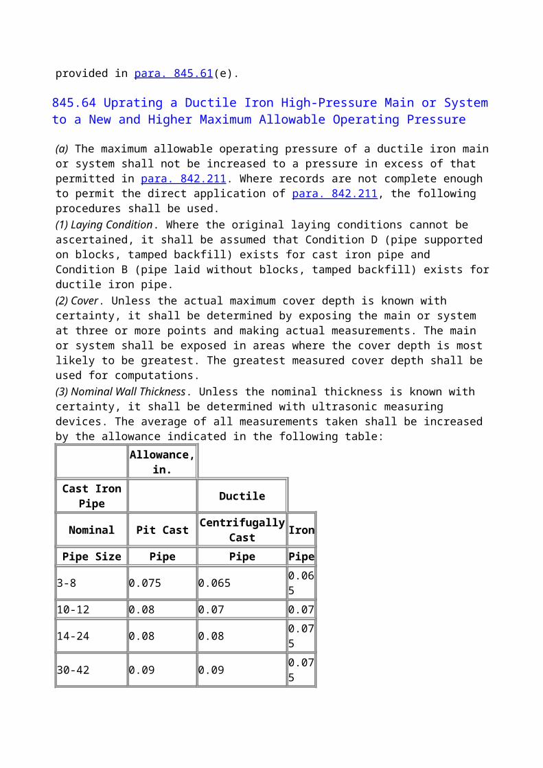
flexible pipe: pipe that is
(a) manufactured from both metal and nonmetal components(b) capable of allowing large deflections without adversely affecting the pipe's integrity(c) intended to be an integral part of the permanent product transportation systemFlexible pipe does not include solid steel pipe, plastic pipe, fiber reinforced plastic pipe, rubber hose, or solid steel pipes lined with nonsteel linings or coatings.
hyperbaric weld: a weld performed at ambient hydrostatic pressure in a submerged chamber from which the water has been removed from the surfaces to be welded.
offshore: the area beyond the line of ordinary high water along the portion of the coast that is in direct contact with the open seas and beyond the line marking the seaward limit of inland coastal waters.
offshore pipeline riser: the vertical or near vertical portion of an offshore pipeline between the platform piping and the pipeline at or below the seabed, including a length of pipe of at least five pipe diameters beyond the bottom elbow, bend, or fitting. Due to the wide variety of configurations, the exact location of transition between pipeline, pipeline riser, and platform piping must be selected on a case-by-case basis.
offshore pipeline system: all components of a pipeline installed offshore for transporting gas other than production facility piping. Tanker or barge loading hoses are not considered part of the offshore pipeline system.
offshore platform: any man-made fixed or permanently anchored structure or artificial island located offshore.
pipe collapse: flattening deformation of the pipe resulting in loss of cross-sectional strength and circular shape, which is caused by excessive external hydrostatic pressure acting alone.
platform piping: due to a wide variety of configurations, the exact location of the transition between the offshore pipeline riser(s), the platform piping, and the production facility shall be selected on a case-by-case basis.
(a) On offshore platforms where hydrocarbons are produced, platform piping consists of all the gas transmission piping, appurtenances, and components that are between the production facility and the off-shore pipeline riser(s). This includes any gas compressors and piping that are not a part of the production facility.(b) On offshore platforms where hydrocarbons are not produced, platform piping consists of all the gas transmission piping, compressors, appurtenances, and components between the offshore pipeline risers.
propagating buckle: a buckle that progresses rapidly along a pipeline caused by the effect of external hydrostatic pressure on a previously formed buckle, local collapse, or other cross-sectional deformation.
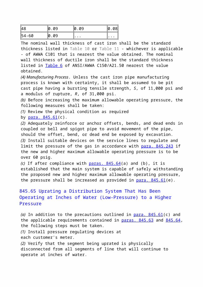
pull tube: a conduit attached to an offshore platform through which a riser can be installed.
pull-tube riser: riser pipe or pipes installed through a pull tube.
return interval: average time interval between successive events of design wave being equalled or exceeded.
soil liquefaction: a soil condition, typically caused by dynamic cyclic loading (e.g., earthquake, waves) where the effective shear stresses in the soil are reduced to zero, and the soil exhibits the properties of a liquid.
splash zone: the area of the pipeline riser or other pipeline components that is intermittently wet and dry due to wave and tidal action.
weight coating: any coating attached to the pipeline for increasing the pipeline specific gravity.
(99)A811 QUALIFICATION OF MATERIALS AND EQUIPMENT
"Unidentified" pipe, plastic pipe, plastic pipe with nonmetallic reinforcement, cast iron pipe, and ductile iron pipe shall not be used for transporting natural gas.
(99)A814 MATERIAL SPECIFICATIONS
(99)A814.1
Concrete weight coating materials (cement, aggregate, reinforcing steel) shall meet or exceed the requirements of applicable ASTM standards.Flexible pipe shall be manufactured from materials meeting the requirements of applicable ASTM or ASME standards.
(99)A814.2
In addition to the requirements contained in referenced standards, certain other requirements may be considered for pipe and other components used off-shore, depending on water depth, water temperature, internal pressure, product composition, product temperature, installation method and/or other loading conditions. Thus, consideration may include one or more of the following:(a) wall thickness tolerance(b) outside diameter tolerance(c) out-of-roundness(d) maximum and minimum yield and tensile strengths(e) maximum carbon equivalent(f) fracture toughness(g) hardness
(h) pipe mill hydrostatic testing and other mechanical testing
(99)A816 TRANSPORTATION OF LINE PIPE
Transportation by truck or other road vehicles shall be performed in such a manner as to avoid damage to the pipe. Provisions shall be made to protect the pipeline corrosion coating, end bevel, and weight coating from damage.
A820 WELDING OFFSHORE PIPELINES
A821 GENERAL
(99)A821.1 Scope
This Section concerns the welding of carbon steel materials that are used in a pipeline in the offshore environment. The welding covered may be performed under atmospheric or hyperbaric conditions.
A821.2 Welding Processes
The welding may be done by any process or combination of processes that produce welds that meet the procedure qualification requirements of this Code and can be inspected by conventional means.
A821.3 Requirements
(a) Prior to atmospheric welding of any pipe, piping components, or related equipment, Welding Procedure Specifications shall be written and the procedure shall be qualified. The approved procedure shall include all of the applicable details listed in API Standard 1104.(b) Prior to hyperbaric welding of any pipe, piping components, or related equipment, Welding Procedure Specifications shall be written and the procedure shall be qualified. The approved procedure shall include all of the applicable details listed in API Standard 1104 and ANSI/AWS D3.6.(c) Each welder or welding operator shall be qualified for the established procedure before performing any welding on any pipe, piping component, or related equipment installed in accordance with this Code.(d) Welding procedure qualifications, as well as welder or welding operator qualifications, are valid only within the specified limits of the welding procedure. If changes are made in certain details, called "essential variables" or "essential changes," additional qualification is required. API Standard 1104 essential variables shall take precedence in matters not affected by the underwater environment, and ANSI/AWS D3.6 shall govern those essential changes related to the underwater welding environment and working conditions.
A823 QUALIFICATION OF PROCEDURES AND WELDERS
Qualification of procedures and welders shall be in accordance with the requirements of para. 823, except paras. 823.1 and 823.2 do not apply offshore.(a) Welding procedures and welders performing atmospheric welding under this section shall be qualified under API Standard 1104, except that for applications in which design, materials,
fabrication, inspection, and testing are in accordance with BPV Code, Section VIII, welding procedures and welders shall be qualified under BPV Code, Section IX(b) Welding procedures and welders performing hyperbaric welding under this section shall be qualified in accordance with the testing provisions of API Standard 1104 as supplemented by ANSI/AWS D3.6, Specification for Underwater Welding for Type "O" Welds.
(99)A825 STRESS RELIEVING
Stress relieving requirements may be waived, regardless of wall thickness, provided that it can be demonstrated that a satisfactory welding procedure without the use of postweld heat treatment has been developed. Such a demonstration shall be conducted on materials and under conditions that simulate, as closely as practical, the actual production welding. Measurements shall be taken of the tensile, toughness, and hardness properties of the weld and heat-affected zone. No stress relieving will be required if(a) the measurements indicate that the metallurgical and mechanical properties are within the limits specified for the materials and intended service(b) an engineering analysis is conducted to ensure that the mechanical properties of the weldment and the residual stresses without postweld heat treatment are satisfactory for the intended service. In some cases, measurement of residual stresses may be required.
A826 WELDING AND INSPECTION TESTS
(99)A826.2 Inspection and Tests for Quality Control of 1991 Welds on Piping Systems
(99)A826.21 Extent of Examination.
One hundred percent of the total number of circumferential field butt welds on offshore pipelines shall be nondestructively inspected, if practical, but in no case shall less than 90% of such welds be inspected. The inspection shall cover 100% of the length of such inspected welds.
(99)A826.22 Standard of Acceptability.
All welds that are inspected must meet the standards of acceptability of API Standard 1104 or BPV Code, Section VIII, as appropriate for the service of the weld, or be appropriately repaired and reinspected or removed.
(99)A826.23 Alternative Flaw Acceptance Limits.
For girth welds on a pipeline, alternative flaw acceptance limits may be established based on fracture mechanics analyses and fitness-for-purpose criteria as described in API Standard 1104. Such alternative acceptance standards shall be supported by appropriate stress analyses, supplementary welding procedure test requirements, and nondestructive examinations beyond the minimum requirements specified herein. The accuracy of the nondestructive techniques for flaw depth measurement shall be verified by sufficient data to establish probabilities for the proposed inspection error allowance.
A830 PIPING SYSTEM COMPONENTS AND FABRICATION DETAILS
A830.1 General
The purpose of this Section is to provide a set of criteria for system components to be used in an offshore application.
(99)A831 PIPING SYSTEM COMPONENTS
Cast iron or ductile iron shall not be used in flanges, fittings, or valve shell components. All system components for offshore applications shall be capable of safely resisting the same loads as the pipe in the run in which they are included, except "weak links" (e.g., break-away couplings) designed into a system to fail under specific loads. Consideration should be given to minimizing stress concentrations.System components which are not specifically covered in para. 831 shall be validated for fitness by either(a) documented full scale prototype testing of the components or special assemblies, or(b) a history of successful usage of these components or special assemblies produced by the same design method. Care should be exercised in any new application of existing designs to ensure suitability for the intended service.
(99)A832 EXPANSION AND FLEXIBILITY
Thermal expansion and contraction calculations shall consider the temperature differential between material temperature during operations and material temperature during installation.
A834 SUPPORTS AND ANCHORAGE FOR EXPOSED PIPING
Supports and anchorage for platform piping and risers shall conform to the requirements of para. 834, except that no attachment, other than an encircling member, shall be welded directly to the pipeline. (See para. A842.27.)
A834 SUPPORTS AND ANCHORAGE FOR EXPOSED PIPING
Supports and anchorage for platform piping and risers shall conform to the requirements of para. 834, except that no attachment, other than an encircling member, shall be welded directly to the pipeline. (See para. A842.27.)
(99)A835 ANCHORAGE FOR BURIED PIPING
Thermal expansion and contraction calculations shall consider the effects of fully saturated backfill material on soil restraint.When a submerged pipeline is to be laid across a known fault zone, or in an earthquake-prone area where new faults are a possibility, consideration shall be given to the need for flexibility in the pipeline system and its components to minimize the possibility of damage due to seismic activity.The requirements of para. 835.51 for header and branch connections are not applicable to offshore
submerged piping systems. An appropriate means of preventing undue stresses at offshore submerged piping connections is to provide adequate flexibility at branch connections on the seabed.
A840 DESIGN, INSTALLATION, AND TESTING
(99)A840.1 General Provisions
The design, installation, and testing of offshore gas transmission systems shall be in accordance with Chapter IV as specifically modified by the provisions of Chapter VIII. Also, all provisions of Chapter IV that depend on location class and construction type do not apply to offshore gas transmission systems, except that offshore pipelines approaching shoreline areas shall be additionally designed and tested consistently with class location provisions as determined in para. A840.2.
(99)A840.2 Shoreline Approaches
Offshore pipelines approaching shoreline areas shall be additionally designed and tested consistently with class location provisions as determined in section 840, except that(a) offshore pipelines in Location Class 3 and 4 may alternatively be hydrostatically tested to a pressure not less than 1.25 times the maximum operating pressure so long as the provisions of section A826 are met(b) for offshore pipelines, the provisions of section A847 supersede para. 841.32.
A841 DESIGN CONSIDERATIONS
A841.1 Design Conditions
A number of physical parameters, henceforth referred to as design conditions, govern design of the offshore pipeline system so that it meets installation, operation, and other post-installation requirements. Some of the factors which may influence the safety and reliability of an offshore pipeline and riser include:(a) waves(b) current(c) marine soils(d) wind(e) ice(f) seismic activity(g) platform motion(h) temperature(i) pressure(j) water depth(k) support settlement(l) accidental loads(m) commercial shipping(n) fishing/shrimping activities
The design of offshore pipelines is often controlled by installation considerations rather than by operating load conditions.
A841.2 Installation Design Considerations
The design of an offshore pipeline system suitable for safe installation and the development of offshore pipeline construction procedures shall be based on consideration of the parameters listed in paras. A841.21 through A841.25. These parameters shall be considered to the extent that they are significant to the proposed system and applicable to the method of installation being considered.
A841.21 Weight.
The effect of pipe or pipeline assembly weights (in air and submerged) on installation stresses and strains shall be considered. Variability due to weight coating manufacturing tolerances and water absorption shall also be considered.
A841.22 Profile.
Variations in water depth along the pipeline route shall be considered. The effect of tides shall be included for locations where such variations are a significant fraction of the water depth. Bottom slope, obstructions, or irregularities which affect installation stresses shall be considered.
A841.23 Environmental Loads.
Local environmental forces including those induced by wind, wave, currents, ice, seismic activity, and other natural phenomenon are subject to radical change in offshore areas. These potential changes should be considered during installation design and contingency planning.
A841.24 Loads Imposed by Construction Equipment and Vessel Motions.
Limitations and behavioral characteristics of installation equipment shall be considered in the installation design.Vessel motions shall be considered if they are expected to result in pipe stresses or pipe/coating damage sufficient to impair the serviceability of the pipeline.
A841.25 Bottom Soils.
Soil characteristics shall be considered when installation procedures are developed for the following:(a) riser installation in pull tubes(b) laying horizontal curves in the pipeline routing(c) pipeline bottom tows(d) trenching and backfilling
A841.3 Operational Design Considerations
A841.31 Loading Classifications.
All parts of the offshore pipeline and riser system shall be designed for the most critical combinations of operational and design environmental loads, acting concurrently, to which the system may be subjected. Wind, wave, and current design loads should be based on a design return interval no less than five times the design life of the pipeline or 100 years, whichever is smaller.If the pipeline operating philosophy is such that operations with full operational loads will be maintained during design storms, then the system shall be designed for concurrent action of operational and design environmental loads.If the operating philosophy is such that operations will be reduced or discontinued during design storm conditions, then the system shall be designed for(a) full operational loads plus maximum coincidental environmental loads(b) design environmental loads plus appropriate reduced operational loadsDirectionality of waves, winds and currents shall be considered to determine the most critical expected combination of above loadings.
A841.32 Operational Loads.
Operational loads that shall be considered are those forces imposed on the pipeline system under static environmental conditions (i.e., excluding wind, waves, current, and other dynamic loadings).Loads that should be considered as operational loads include(a) weight of unsupported span of pipe, including (as appropriate) the weight of(1) pipe(2) coatings and their absorbed water(3) attachments to the pipe(4) transported contents(b) internal and external pressure(c) thermal expansion and contraction(d) buoyancy(e) prestressing (exclusive of structurally restrained pipe configurations, such as in a pull-tube riser bend)(f) static soil induced loadings (e.g., overburden) The effects of prestressing, such as permanent curvatures induced by installation, should be considered when they affect the serviceability of the pipeline.
A841.33 Design Environmental Loads.
Loadings that should be considered under this category include, as appropriate, those arising due to(a) waves(b) current(c) wind(d) seismic events(e) accidental loadings (e.g., trawl boards, anchors)(f) dynamic soil induced loadings (e.g., mudslides, liquefaction)(g) ice loads (e.g., weight, floating impacts, scouring)
A842 STRENGTH CONSIDERATIONS
Design and installation analyses shall be based on accepted engineering methods, material strength, and applicable design conditions.
A842.1 Strength Consideration During Installation
The following subsections define the minimum safety requirements against failure due to yielding or buckling during all phases of pipeline system installation (i.e., handling, laying, trenching, etc., through testing).
A842.11 Buckling.
The pipeline should be designed and installed in a manner to prevent buckling during installation. Design and procedures for installation should account for the effect of external hydrostatic pressure, bending moment, axial, and torsional loads and pipe out-of-roundness. Consideration should also be given to the buckle propagation phenomenon.
A842.12 Collapse.
The pipe wall thickness shall be designed to resist collapse due to external hydrostatic pressure. Considerations shall include the effects of mill tolerances in the wall thickness, out-of-roundness, and any other applicable factors.
A842.13 Allowable Longitudinal Stress.
The maximum longitudinal stress due to axial and bending loads during installation shall be limited to a value that prevents pipe buckling and will not impair the service-ability of the installed pipeline.
A842.14 Allowable Strains.
Instead of the stress criteria of para. A842.13, an allowable installation strain limit may be used. The maximum longitudinal strain due to axial and bending loads during installation shall be limited to a value that prevents pipe buckling and will not impair the serviceability of the installed pipeline.
A842.15 Installation Fatigue.
Anticipated stress fluctuations of sufficient magnitude and frequency to induce significant fatigue shall be considered in design.
A842.16 Special Assemblies.
Installation of pipelines with special assemblies (such as tap valves and riser offsets) are subject to the same requirements stated in paras. A842.11 through A842.15.
A842.17 Residual Stresses.

The pipeline system shall normally be installed in a manner so as to minimize residual stresses. The exception shall be when the designer purposefully plans for residual stresses (e.g., cold springing of risers, pull-tube risers). When residual stresses are significant, they should be considered in the operating design of the pipeline system (see para. A842.2).
(99)A842.18 Flexible Pipe.
The manufacturers recommended maximum loadings and minimum bending radius shall be adhered to during installation. Flexible pipe shall be designed or selected to prevent collapse due to the combined effects of external pressure, axial forces, and bending. Installation procedures shall be designed to prevent buckling. (See API RP 17B.)
A842.2 Strength Considerations During Operations
A842.21 Operational and Design Criteria
A842.211
Pipelines and risers shall be designed against the following possible modes of failure, as appropriate:(a) excessive yielding(b) buckling(c) fatigue failure(d) ductile fracture(e) brittle fracture(f) loss of in-place stability(g) propagating fracture(h) corrosion(i) collapse
A842.212
Furthermore, consideration shall be given to impacts due to(a) foreign objects(b) anchors(c) trawlboards(d) vessels, ice keels, etc.
A842.22 Design Against Yielding
A842.221 Hoop Stress.
For pipelines and risers the tensile hoop stress due to the difference between internal and external pressures shall not exceed the values given below:
NOTE: Sign convention is such that tension is positive and compression is negative.
where
D = nominal outside diameter of pipe, in.
F1 = hoop stress design factor from Table A842.22
Pe = external pressure, psi
Pi = internal design pressure, psi
S = specified minimum yield strength, psi
Sh = hoop stress, psi
T = temperature derating factor from Table 841.116A
t = nominal wall thickness, in.
(99)A842.222 Longitudinal Stress.
For pipelines and 1991 risers the longitudinal stress shall not exceed values found from
where
A = cross sectional area of pipe material, in.2
Fa = axial force, lbs;
F2 = longitudinal stress design factor from Table A842.22
Mi = in-plane bending moment, in.-lb
Mo = out-plane bending moment, in.-lb
S = specified minimum yield strength, psi
SL = maximum longitudinal stress, psi (positive tensile or negative compressive)
= Sa + Sb or Sa - Sb, whichever results in the larger stress value
Sa = axial stress, psi (positive tensile or negative compressive)
= Fa / A
Sb = resultant bending stress, psi
= [(iiMi)2 + (ioMo)2]1/2/z
ii = in-plane stress intensification factor from Appendix E
io = out-plane stress intensification factor from Appendix E
z = section modulus of pipe, in.3
= absolute value
(99)A842.223 Combined Stress.
For pipelines and risers the combined stress shall not exceed the value given by the maximum shear stress equation (Tresca combined stress):
where
A = cross-sectional area of pipe material, in.2
Fa = axial force, lbs
F3 = combined stress design factor from Table A842.22
Mi = in-plane bending moment, in.-lb
Mo = out-plane bending moment, in.-lb
Mt = torsional moment, in.lb
S = specified minimum yield strength, psi
SL = maximum longitudinal stress, psi (positive tensile or negative compressive)
= Sa + Sb or Sa - Sb, whichever results in the larger stress value
Sa = axial stress, psi (positive tensile or negative compressive)
= Fa / A
Sb = resultant bending stress, psi
= [(iiMi)2 + (ioMo)2]1/2/z
Sh = hoop stress, psi
St = torsional stress, psi
ii = in-plane stress intensification factor from Appendix E
io = out-plane stress intensification factor from Appendix E
z = section modulus of pipe, in.3
Alternatively, the Maximum Distortional Energy Theory (Von Mises combined stress) may be used for limiting combined stress values. Accordingly, the combined stress should not exceed values given by
A842.23 Alternate Design for Strain.
In situations where the pipeline experiences a predictable noncyclic displacement of its support (e.g., fault movement along the pipeline route or differential subsidence along the line) or pipe sag before support contact, the longitudinal and combined stress limits need not be used as a criterion for safety against excessive yielding, so long as the consequences of yielding are not detrimental to the integrity of the pipeline. The permissible maximum longitudinal strain depends on the ductility of the material, any previously experienced plastic strain, and the buckling behavior of the pipe. Where plastic strains are anticipated, the pipe eccentricity, pipe out-of-round- ness, and the ability of the weld to undergo such strains without detrimental effect should be considered. Similarly, the same criteria may be applied to the pipe during construction (e.g., pull-tube or bending shoe risers).
A842.24 Design Against Buckling and Ovalization.
Avoidance of buckling of the pipeline and riser during operation shall be considered in design. Modes of buckling that may be possible include(a) local buckling of the pipe wall(b) propagation buckling following local buckling(c) column buckling
A842.25 Design Against Fatigue.
Stress fluctuations of sufficient magnitude and frequency to induce significant fatigue should be considered in design.Loadings that may affect fatigue include:(a) pipe vibration, such as that induced by vortex shedding(b) wave actionPipe and riser spans shall be designed so that vortex induced resonant vibrations are prevented, whenever practical. When doing so is impractical, the total resultant stresses shall be less than the allowable limits in para. A842.22, and such that fatigue failure should not result during the design life of the pipeline.
A842.26 Design Against Fracture.
Materials used for pipelines transporting gas or gas-liquid mixtures under high pressure should have reasonably high resistance to propagating fractures at the design conditions, or other methods shall be used to limit the extent of a fracture.
A842.27 Design of Clamps and Supports.
Clamps and supports shall be designed such that a smooth transfer of loads is made from the pipeline or riser to the supporting structure without highly localized stresses due to stress concentrations. When members are to be welded to the pipe they shall fully encircle the pipe and be welded to the pipe by a full encirclement weld. The support shall be attached to the encircling member and not the pipe.All welds to the pipe shall be nondestructively tested. Clamps and supports shall be designed in accordance with the requirements of API RP 2A, Section 3.Clamp and support design shall consider the corrosive effects of moisture retaining gaps and
crevices and galvanically dissimilar metals.
A842.28 Design of Connectors and Flanges.
Connectors and flanges shall be such that smooth transfer of loads is made without high localized stresses or excessive deformation of the attached pipe.Connectors and flanges shall have a level of safety against failure by yielding and failure by fatigue that is comparable to that of the attached pipeline or riser.
A842.29 Design of Structural Pipeline Riser Protectors.
Where pipeline risers are installed in locations subject to impact from marine traffic, protective devices shall be installed in the zone subject to damage to protect the pipe and coating.
A842.30 Design and Protection of Special Assemblies.
Design of connections and special assemblies, such as subsea tie-in assemblies, expansion loops, sea-bed riser connections, and subsea pipeline manifolds, shall consider the additional forces and effects imposed by a subsea environment. Such additional considerations include design storm currents and potential for seabed movement in soft sediments, soil liquefaction, increased potential corrosion, thermal expansion and contraction, and stress due to installation procedures. In areas of active fishing, protective measures may be appropriate for connections and special assemblies.
(99)A842.31 Design of Flexible Pipe.
Due to its composite makeup, the mechanical behavior of flexible pipe is significantly different from steel pipe. Flexible pipe may be used for offshore pipelines if calculations and/ or test results verify that the pipe can safely withstand loadings considered in paras. A841.32 through A841.33. In the selection of flexible pipe, consideration should be given to its permeable nature. The possibility of implosion under the combined conditions of high pressure, high temperature, and very rapid depressurization should be investigated where such conditions may be expected. Selection of flexible pipe shall be in accordance with API RP 17B.
(99)A843 COMPRESSOR STATIONS
(99)A843.1 Compressor Station Design
The requirements of this section recognize the unique design conditions and space limitations imposed when designing offshore compression facilities and therefore relate only to offshore compression facilities. It is the further intent of this section to make the designer aware of personnel safety during the design and operation of offshore compression facilities.
(99)A843.11 Location of Compressor Facilities.
The compressor facilities located on platforms should be designed to facilitate free movement of fire fighting or other emergency equipment.
(99)A843.12 Enclosures.
All enclosures located on an offshore platform shall be constructed of noncombustible or limited combustible material as defined in NFPA 220, Chapter 2, Section 2-6 and Section 2-3. Design of enclosures on offshore platforms shall consider the loading conditions defined in para. A841.3.
(99)A843.13 Exits.
A minimum of two exits shall be provided for each operating level of a compressor building. Any elevated walkway, including engine cat-walks more than 10 ft above the deck, shall also be provided with two exits. The maximum distance from any point within the compressor building to an exit shall not exceed 75 ft. Enclosure exits shall be unobstructed and located so as to provide a convenient route of escape and shall provide continuous unobstructed passage to a place of safety. Exit doors located on exterior walls shall swing outward and shall be equipped with latches that can be readily opened from the inside without a key.
(99)A843.2 Electrical Facilities
All electrical equipment and wiring installed on offshore compression platforms shall conform to the requirements of NFPA 70, if commercially available equipment permits.Electrical installations in offshore hazardous locations as defined in NFPA 70 Chapter 5, Article 500 and that are to remain in operation during compressor station emergency shutdown as provided in para. A844.431 shall be designed to conform to NFPA 70, for Class I, Division I requirements.The guidelines of API-RP-14F should be considered in electrical facility design.
(99)A843.4 Compressor Station Equipment
(99)A843.43 Safety Devices
(99)A843.431 Emergency Shutdown Facilities.
All gas compression equipment shall be provided with an emergency shutdown system that will block out the gas going to and from the compressor station. Operation of the emergency shutdown system shall cause the shutdown of all gas compression equipment and all gas fired equipment and shall de-energize the electrical facilities in the compressor building, except for those that provide emergency lighting for personnel protection and those that are necessary for protection of equipment. The emergency shutdown system shall be operable from a minimum of two locations on each deck level; that is, should an offshore platform facility have more than one clearly defined deck, each deck shall have a minimum of two shutdown locations. Blowdown piping shall extend to a location where the discharge of gas is not likely to create a hazard to the platform facilities. Consideration should be given to potential entrained liquids, prevailing winds, and location of crew quarters if part of the platform facility. Under conditions of heavy liquid entrainment and poor prevailing wind conditions, a separate structure for a blowdown facility shall be considered.
(99)A843.44 Pressure Limiting Requirements for Offshore Compression Facilities
(99)A843.443 Venting.
Pressure relief valves shall be vented to atmosphere such that no hazard is created. Vent lines,

common headers, and platform blowdown lines shall have sufficient capacity so that they will not interfere with the performance of the relief device.
(99)A844 ON-BOTTOM STABILITY
Pipeline design for lateral and vertical stability is governed by seafloor bathymetry, soil characteristics, and by hydrodynamic, seismic, and soil behavior events having a significant probability of occurrence during the life of the system. Design conditions to consider are provided in following subsections.The pipeline system shall be designed to prevent horizontal and vertical movements, or shall be designed so that any movements will be limited to values not causing design strength to be exceeded (see para. A842).Typical factors to be considered in the stability design include(a) wave and current forces(b) scour and resultant spanning(c) liquefaction(d) slope failureStability may be obtained by such means including, but not limited to, pipe submerged weight, trenching of pipe below grade, and anchoring.When calculating hydrodynamic forces, the spatial variance of wave forces along the length of the pipeline may be taken into account.
A844.1 Design Storm Conditions
Design wave and current conditions for portions of a pipeline that will not be trenched shall be based on a storm having a minimum return interval of no less than five times the design life or 100 years, whichever is smaller. Portions of the pipeline system to be trenched shall be designed for wave and current conditions based on prudent assessment of the period of pipe exposure. The most unfavorable expected combination of wave and current conditions shall be used. Maximum wave and maximum current conditions do not necessarily occur simultaneously. The most unfavorable condition selection shall account for the timing of occurrence of the wave and current direction and magnitude.
A844.2 Stability Against Waves and Currents
A844.21 Submerged Weight.
The submerged weight of the pipe may be designed (such as by weight coating) to resist or limit movement to acceptable values. Hydrodynamic forces shall be based on the wave and current values for the design storm condition for the specific location.Wave and current directionality and concurrency shall be considered.
A844.22 Bottom Soils.
The pipe-soil interaction factors that are used shall be representative of the bottom conditions at the site.
A844.23 Trenching.
The pipeline and its appurtenances may be trenched below bottom grade to provide stability. The pipeline must be designed for wave and current stability prior to trenching. Such stability, however, need only be based on environmental conditions expected during the period of pipe exposure.
A844.24 Backfilling.
Backfilling or other protective coverings, when necessary, shall be accomplished by using such materials and procedures to preclude damage to the pipeline and coatings.
A844.25 Anchoring.
Anchoring may be used instead of or in conjunction with submerged weight to maintain stability. The anchors shall be designed to withstand lateral and vertical loads expected from the design storm condition. Anchors shall be spaced to prevent excessive stresses in the pipe sections between anchors. The anchoring system and adjacent pipe shall be designed to prevent scour and resultant spanning from overstressing the pipe. The effect of anchors on the cathodic protection system shall be considered.
A844.3 Shore Approaches
Pipe in the shore approach zone shall be trenched or bored to the depth necessary to prevent scouring, spanning, or stability problems that affect integrity and safe operation of the pipeline during its anticipated service life. Seasonal variation in the near shore thickness of seafloor sediments and shoreline erosion over the pipeline service life shall be considered.
A844.4 Slope Failure
The pipeline shall be designed for slope failure in zones of known or anticipated occurrence, such as mudslide zones and areas of seismic slumping. The design exposure period shall be no less than the expected life of the pipeline. If it is not practical to design the pipeline system to survive the event, the pipeline shall be designed for controlled breakaway with check valving to prevent blowdown of the pipeline.
A844.5 Soil Liquefaction
Design for the effects of liquefaction shall be performed for areas of known or expected occurrence. Soil liquefaction normally results from cyclic wave overpressures or seismic loading of susceptible soils. The bulk specific gravity of the pipeline shall be designed, or alternative methods shall be selected to ensure both horizontal and vertical stability.Seismic design conditions used to predict the occurrence of bottom liquefaction or slope failure shall have the same recurrence interval as used for the operating design strength calculations for the pipeline. Occurrence of soil liquefaction due to wave overpressures shall be based on a storm return interval of no less than five times the design life or 100 years, whichever is smaller.
A845 CONTROL AND LIMITING OF GAS PRESSURE
All applicable provisions of para. 845 apply unless otherwise stated.
A846 VALVES
Offshore transmission lines shall be equipped with valves or other components to shut off the flow of gas to an offshore platform in an emergency.Block valves shall be accessible and protected from damage and tampering. If a blowdown valve is involved, it shall be located where the gas can be blown to the atmosphere without undue hazard.Blowdown valves shall be provided so that each section of pipeline between main line valves can be blown down. The sizes and capacity of the connections for blowing down the line shall be such that under emergency conditions the section of line can be blown down as rapidly as is practicable
A847 TESTING
A847.1 General Provisions
All offshore pipelines shall be tested after installation and prior to operation within the provisions of this section.
A847.2 Test Pressure
The installed pipeline system shall be hydrostatically tested to at least 1.25 times the maximum allowable operating pressure. Offshore platform piping and off-shore pipeline risers must be tested to at least 1.4 times the maximum allowable operating pressure either before or after installation. Prefabricated portions of platform piping that have been pretested to 1.4 times the maximum allowable operating pressure need not be tested after installation if all items are tied in by connectors, flanges, or welds that have been radiographically inspected.
A847.3 Test Medium
The test medium for all offshore pipelines will be water. Additives to mitigate the effects of corrosion, biofouling, and freezing should be considered. Such additives should be suitable for the methods of disposal of the test medium.In arctic areas where freezing of water is a hazard, the use of air, inert gas, or glycol is allowable. Platform gas and compression piping may be tested with inert gas.
A847.4 Test Procedure
The hydrostatic pressure test shall be conducted in accordance with a specified procedure that shall, at a minimum, provide for(a) performance of the test after installation and before initial operation of the pipeline system except as provided in para. A847.2(b) the inclusion of prefabricated, pretested portions of offshore pipeline risers in the pipeline system hydrostatic test, whenever practical(c) maintenance of the test and recording of results on pipeline and assemblies for a minimum of eight continuous hours at or above the specified pressure. All variations in test pressure shall be accounted for. Test duration of prefabricated piping may be 2 hr.(d) a retest if, during the hold time, a rupture or hazardous leak occurs that renders the test invalid.

Retesting shall commence after repairs have been made.
A847.5 Records
The operating company shall maintain in its file, for the useful life of each pipeline, records showing the type of test fluid, the test procedure, the test pressure, and the duration of the test.
A847.6 Tie-ins
It is recognized that it may not be possible to hydrostatically test the tie-in between two test sections. Pressure testing of tie-in welds may be exempted if the tie-in weld is inspected by radiographic and/or other applicable NDT methods.
A847.7 Testing for Buckles
Testing for buckles, dents, and other diameter restrictions shall be performed after installation. Testing shall be accomplished by passing a deformation detection device through the pipeline section, or by other methods capable of detecting a change in pipe diameter. Pipe having excessive deformation which affects the service-ability of the pipeline facilities shall be repaired or replaced. Consideration should also be given to repairing excessive ovality which may interfere with pigging operation or internal inspection.
A850 OPERATING AND MAINTENANCE PROCEDURES AFFECTING THE SAFETY OF GAS TRANSMISSION AND DISTRIBUTION FACILITIES
(99)A850.1 General
All provisions of Chapter V, which depend on location class, do not apply to offshore gas transmission systems, except that offshore pipelines approaching shoreline areas shall additionally be operated and maintained consistently with class location provisions as determined in section 840.
(99)A850.3 Essential Features of the Operating and Maintenance Plan
The plan prescribed in para. 850.2(a) shall include(a) detailed plans and instructions for employees covering operating and maintenance procedures for gas facilities during normal operations and repairs(b) items recommended for inclusion in the plan for specific classes of facilities, which are given in paras. A851.2, A851.4, and A860(c) plans to give particular attention to those portions of the facilities presenting the greatest hazard to the public and environment in the event of an emergency or because of construction or extraordinary maintenance requirements(d) provisions for periodic inspections along the route of existing pipelines
A850.4 Essential Features of the Emergency Plan
A850.43 Liaison.
Each operating company shall establish and maintain liaison with available offshore fire fighting entities (public and or privately owned) that might be designated for any particular offshore area.
A850.44 Educational Program.
An educational program shall be established to enable producers and the general public operating in the offshore area to recognize and report a gas emergency to the appropriate officials. The educational program called for under this section should be tailored to the type of pipeline operation and the environment traversed by the pipeline and should be conducted in each language that is significant in the community served. Operators of transmission systems should communicate their programs to people, contractors, or others that usually work in the offshore area of concern. The programs of operators in the same area should be coordinated to properly direct reports of emergencies and to avoid inconsistencies.
A850.7 Blasting Effects
Each operating company shall establish procedures for protection of facilities in the vicinity of blasting activities. The operating company shall(a) locate and mark its pipeline when explosives are to be detonated within distances as specified in company plans. Consideration should be given to the marking of minimum blasting distances from the pipelines depending on the type of blasting operation.(b) determine the necessity and extent of observing or monitoring blasting activities based on the proximity of the blast considering the pipe materials, the operating conditions, the size of charge, and soil conditions(c) consideration should be given to(1) the effect of shock waves on the pipeline from blasting(2) conducting a leak survey following completion of the blasting program
A851 PIPELINE MAINTENANCE
(99)A851.2 Pipeline Patrolling
Each operating company shall maintain a periodic pipeline patrolling program to observe conditions on and adjacent to the pipeline right-of-way, indication of leaks, construction activity other than that performed by the company, and any other factors affecting the safety and operation of the pipeline. These inspections should be made as often as necessary to maintain the integrity of the pipeline. Records of these inspections shall be maintained for the life of the facility. Provisions of paras. 851.2, 851.21, and 851.22 do not apply to this chapter.
A851.4 Above Water and Hyperbaric Repair Procedures for Steel Pipelines
All above water and hyperbaric repair procedures for steel pipelines shall conform to the requirements of para. 851.4 as specified for pipelines operating at or above 40% of the specified minimum yield strength.
A851.45 Offshore Below Water Repair Procedures for Steel Pipelines.
Submerged offshore pipelines may be repaired by replacement of the damaged section or by the use of a full encirclement split sleeve of appropriate design installed over the imperfection or damage. Replacement sections and split sleeves shall be secured by atmospheric dry or hyperbaric welding or mechanical devices. Repairs shall be visually inspected for leaks after being returned to service.Any offshore below-water repair procedures shall conform to para. 851.4 provisions for pipelines operating at or above 40% of the specified minimum yield strength.Repairs should be performed under qualified supervision by trained personnel aware of and familiar with the maintenance plan and operating conditions of the pipeline, the company's safety requirements, and the hazards to public safety and environment.Evacuation and repair operations should not result in imposed loads or deformations that would impair the integrity of the pipe materials, weight, or protective coating.The use of subsurface equipment equipped with cutters, ejectors, jets, or air suction systems should be carefully controlled and monitored to avoid damaging the pipeline, external coating, or cathodic protection system.When lifting or supporting pipe during repairs, the curvature of a pipe sag bend and overbend should be controlled and maintained within limits to minimize pipe coating damage, overstressing, denting or buckling during the repair operation, and lifting equipment should be selected accordingly.Wave and current loads should be considered in determining total imposed stresses and cyclical loads in both surface and subsurface repairs.Personnel working on pipeline repairs should understand the need for careful job planning, be briefed on procedures to be followed in accomplishing repairs, and follow necessary precautionary measures and procedures.When pipe is repaired, damaged coating should also be repaired. Replacement pipe and components shall be protected from corrosion.
A851.46 Offshore Repair of Flexible Pipe.
If the operability of the flexible pipe is impaired, i.e., major structural damage, the pipe shall be repaired by replacement of the damaged section. In the event of surface cuts and abrasions in the protective coating that do not expose the load carrying members to potential corrosion, the repair shall be performed in a manner recommended by the manufacturer.
A851.7 Pipeline Markers
Permanent markers are not required for offshore pipelines; however, suitable signs should be posted on platforms to serve as a hazard area warning. Where appropriate, signs should display the operating company identification and emergency communication procedures.
(99)A854 LOCATION CLASS
There are no operating location classes offshore.
A860 CORROSION CONTROL OF OFFSHORE PIPELINES
(99)A861 SCOPE
Since offshore pipelines cannot be, readily inspected after installation and there is the possibility of damage to the coating system, special consideration should be given to the selection, design, and application of corrosion control coatings, the cathodic protection system, and other corrosion design elements
A862 EXTERNAL CORROSION CONTROL
(99)A862.1 New Installations
All submerged steel pipe, valves, and related fittings shall be externally coated and cathodically protected. All above-water piping and components shall be protected from the particularly corrosive conditions of the salt water atmosphere and cyclic wetting and drying.
(99)A862.11 Submerged Facilities
(99)A862.12 Coating Requirements
(a) Coating Design. The design of coating systems for offshore installation should reflect the type of environment in which the facility is to be installed. Selection of the protective coating should be based on(1) low water-absorption(2) compatibility with the type of cathodic protection to be applied to the system(3) compatibility with the system operating temperature(4) sufficient ductility to minimize detrimental cracking(5) sufficient toughness to withstand damage during installation(6) resistance to future deterioration in a submerged environment(7) ease of repair(b) Cleaning and Surface Preparation. There may be additional cleaning and surface preparation requirements, such as a near white metal finish and an anchor pattern to promote a good bond for all epoxy-based thin film coatings. Welds should be inspected for irregularities that could protrude through the pipe coating, and any such irregularities should be removed.(c) Application and Inspection. The coating should be applied under controlled conditions and have a high resistance to disbondment. Further information can be obtained from NACE RP-06-75, Section 4. A holiday detector, suitable for the type of coating applied, shall be used to detect flaws. Flaws noted shall be repaired and retested. Weights or weight coating shall not damage the protective coating during application or installation.(d) Coating for Weld Joints, Appurtenances, and Patching. Weld joints and appurtenances shall be coated with material that is compatible with the basic coating. A holiday detector, designed for the type of field joint material applied, may be used to detect flaws, and flaws shall be repaired and retested.(e) Field Inspection. The pipe shall be visually inspected prior to installation to ensure that unacceptable damage has not occurred during loading, welding, or other laying activities prior to submergence of the pipe. Any significant damage to the coating shall be repaired with material compatible with the pipeline coating. Care should be exercised to minimize damage to the coating system, particularly during laying and trenching of the pipe.
(99)A862.13 Cathodic Protection Requirements
(a) Design Criteria. An offshore facility is considered to be cathodically protected when it meets one or more of the criteria established in Appendix K.(b) Impressed Currents. Where impressed current systems are used, the system shall be designed to minimize outages, and the output shall be such that the design criterion is met. Also, consideration should be given to minimize the interference effect on other pipelines or structures.(c) Galvanic Anodes. Where galvanic anodes are used for protection, consideration shall be given to the quality of the coating (i.e., the percent of exposed pipe). Also, the design formula for the system should include the output of the anodes, the desired life of the system, anode material, and utilization efficiency. Anodes used should be compatible with the operating temperature of the pipeline and the marine environment.(d) Other. Consideration should be given to the effects on cathodic protection of variations in oxygen content, temperature, and water/soil resistivity of the particular offshore environment in which the pipeline is installed.
(99)A862.14 Electrical Isolation.
Underwater pipeline systems shall be electrically isolated from other metallic structures so that cathodic protection can be effective. An exception can be made when both the foreign structure and the pipeline are designed to be protected as a unit. Other general considerations include the following:(a) Tie-Ins. Isolation from foreign pipelines at tie-ins may be made by installing insulation flanges, unions, or other insulating devices. When making a tie-in of a coated line to a bare line, the two lines shall be electrically isolated.(b) Foreign Pipeline Crossings. When crossing a foreign pipeline, care shall be exercised to ensure adequate separation between the two lines so that the possibility for electrical interference is minimized.(c) Pipeline Riser Support and Secondary Piping. When installing riser piping at platforms, supporting devices such as clamps and pipe supports shall isolate the piping from the structure. Insulating devices shall be installed where electrical isolation of a portion of the piping system from production piping, tanks, and other facilities is necessary to facilitate application of cathodic protection. Electrical interference between electrically isolated structures shall be minimized. Wiring and piping connections to an isolated pipeline shall also have insulation between the pipeline and the platform. Tests shall be made to ensure adequate isolation, and appropriate action shall be taken to ensure such isolation when necessary.
(99)A862.15 Electrical Connections and Monitoring Points.
Test leads shall be installed so that they are mechanically secure, electrically conductive, and accessible for testing. It is considered impractical to locate test leads in deep or open water. Test leads installations are usually limited to platforms and the pipeline entrance to the shore.
(99)A862.16 Atmospheric Protection
(a) The splash zone area, where the pipeline is intermittently wet and dry, shall be designed with additional protection against corrosion. This shall be accomplished by one or more of the following:(1) special coating(2) special protective systems and techniques
(3) other suitable measures, including selection of pipe material(b) Coatings and other protective systems shall be installed on a properly prepared surface and in accordance with established specifications or manufacturer's recommendations. The coating should resist water action, atmospheric deterioration, mechanical damage, and cathodic disbondment.
(99)A862.2 Existing Installations
The operating company must rely on monitoring, investigation, inspections, and corrective action to control corrosion. Such activities shall be performed at periodic intervals sufficient to ensure that adequate corrosion control is maintained. Where it is determined that corrosion that is taking place may be detrimental to public or employee safety, the facility shall be repaired or replaced, and corrosion control measures shall be applied or augmented.
(99)A862.21 Submerged Facilities
(99)A862.214 Cathodic Protection Criteria
(a) Criteria. The criteria for cathodic protection are specified in Appendix K.(b) Electrical Checks. The operating company shall take electrical readings periodically at each test location available to ensure that the cathodic protection level meets one of the criteria in Appendix K.Before each electrical test is performed, an inspection shall be made to ensure electrical continuity and that a good contact to the pipelines is made by the test connection.
(99)A862.215 Electrical Interference.
Periodic tests shall be made to ensure that electrical isolation from foreign pipelines or other structures remains complete. Some indications of electrical interference are changes in pipe to electrolyte potential, changes in current magnitude or direction, localized pitting, and coating breakdown. When new foreign pipelines are laid in the vicinity of existing lines, inspections shall be made to ensure electrical isolation in accordance with para. 862.114. If electrical isolation cannot be attained, measures shall be taken to minimize electrical interference. Electrical isolation from the platform should be checked and maintained unless the system was specifically designed to be jointly protected.
(99)A862.216 Examination When Exposed.
When a pipeline is lifted above water for maintenance or repair, the operating company shall visually inspect for evidence of coating deterioration, external corrosion, and where possible, the condition of any exposed anode. If excessive corrosion is present, remedial action shall be taken as necessary.If repairs are made below water, inspection for evidence of external corrosion or coating deterioration shall be made, and necessary corrective action shall be taken to maintain the corrosion protection of the pipeline.
(99)A862.25 Atmospheric Corrosion.
Detailed inspections shall be made periodically of all piping for atmospheric corrosion. This
inspection shall include those areas most susceptible to corrosion such as flanges, flange bolts, areas under pipe straps, areas where pipe is in contact with supports, and other places where moisture collects. Where atmospheric corrosion is found, prompt corrective action shall be taken. Corrective action shall consist of painting, replacement of components as necessary, or other action deemed appropriate by the operating company.
(99)A863 INTERNAL CORROSION CONTROL
(99)A863.1 General
The design and maintenance of offshore pipeline facilities that may carry natural gas containing carbon dioxide, chlorides, hydrogen sulfide, organic acids, solids or precipitates, sulfur-bearing compounds, oxygen, or free water require special consideration for the control of internal corrosion.
(99) CHAPTER IX SOUR GAS SERVICE
B800 SOUR GAS SERVICE
B801GENERAL
Chapter IX pertains only to gas pipeline service that contains hydrogen sulfide levels defined as "sour gas" in this Chapter. This Chapter is organized to parallel the numbering and content of the first seven chapters of the Code. All provisions of the first seven chapters of the Code are also requirements of this Chapter unless specifically modified herein. Paragraph headings follow those in the first seven chapters with the prefix "B".If a paragraph appearing in Chapters I through VH does not have a corresponding paragraph in this Chapter, the provisions apply to sour gas service without modification. If a paragraph in this Chapter has no corresponding paragraph in Chapters I through VII, the provisions apply to sour gas only.
B802 SCOPE AND INTENT
B802.1 Scope
This Chapter of the Code covers the design, material requirements, fabrication, installation, inspection, testing, and safety aspects of operation and maintenance of sour gas systems.
B802.2 Intent
The intent of this Chapter is to provide adequate requirements for the safe and reliable design, installation, operation, and maintenance of sour gas service pipeline systems. Requirements of this Chapter supplement the requirements of the remainder of the Code. It is not the intent of this Chapter to be all inclusive. Provisions must be made for special considerations that are not specifically addressed. This Chapter is not intended to prevent the development and application of new equipment and technology. Such activity is encouraged as long as the safety and reliability requirements of the Code are satisfied.
B803 SOUR GAS TERMS AND DEFINITIONS
hardness: resistance of metal to plastic deformation usually by indentation. For carbon steels, hardness can be related to the ultimate tensile strength.
Brinell Hardness Number (BHN): a value to express the hardness of metals obtained by forcing a hard steel ball of specified diameter into the metal under a specified load. For the standard 3,000-kg load, numbers range from 81 to 945.Microhardness: any hardness measurement using an indentor load less than 10 kg.Rockwell Hardness: a series of hardness scales for metals.(a) The Rockwell "C" (HRC) scale uses a cone diamond indentor and a load of 150 kg. The scale starts at 20 for soft steels and reaches a maximum of about 67 for very hard alloys.(b) The Rockwell "B" (HRB) scale uses a hard metal ball indentor and starts at 0 for extremely soft metals and reaches a maximum of 100 for soft steels and alloys. HRB 100 = HRC 20.Vickers Hardness HV 10: a value achieved by use of a diamond pyramid indentor with a load of 10 kg.
heat affected zone (HAZ): the portion of the base metal that was not melted during brazing, cutting, or welding, but whose microstructure and properties were affected by the heat of these processes.
hydrogen induced cracking (HIC): a cracking mechanism of susceptible materials caused by atomic hydrogen diffusion in the metal. The atomic hydrogen usually is created by the corrosive reaction of hydrogen sulfide on steel in the presence of water.
hydrogen sulfide (H2S): a toxic gaseous impurity found in some well gas streams. It also can be generated in situ as a result of microbiologic activity.
partial pressure: determined by multiplying the mol fraction (mol percent divided by 100) of hydrogen sulfide in the gas by the total system pressure.
radius of exposure (ROE): the distance from a point of release at which the hydrogen sulfide concentrations reached a specified level (frequently 100 ppm or 500 ppm) determined by dispersion calculations.
sour gas: gas containing hydrogen sulfide (H2S) at 65 psia (4.5 Bar) or greater at a partial pressure of 0.05 psia (3.5 m Bar) or greater. See NACE MR0175, titled Sulfide Stress Cracking Resistant-Metallic Materials for Oilfield Equipment.
sulfide stress cracking (SSC):a corrosion-related cracking mechanism caused by exposure of susceptible materials to sulfide ions in the presence of free water.
B813 MARKING
Valves meeting NACE MR0175 shall be so identified with a permanent tag or marking.
B814 MATERIAL SPECIFICATIONS
B814.1 General Requirements
Materials must meet the requirements of NACE MR0175.
B820 WELDING SOUR GAS PIPELINES
B821GENERAL
B821.1
This section concerns the welding of pipe in sour gas service in both wrought and cast steel materials and covers butt and fillet welded joints in pipe, valves, flanges, fittings, and fillet welded joints in pipe, slip-on flanges, socket welds, fittings, etc. as applied in pipelines, components, and connections to apparatus or equipment.
B821.2 Seam Welds
This section does not apply to the welding of the seam in the manufacture of pipe, but the user is cautioned to ensure that such seams are suitable for sour gas service in their installed condition.
B821.4
The standards of acceptability for welds of piping systems as established in API-1104, Section 6, or ASME Boiler and Pressure Vessel Code, Section VIII, Division 1, shall be used; however, additional requirements for hardness and residual stress should be considered.
B822 PREPARATION FOR WELDING
B822.3 Seal Welds
Seal welds shall have a separate qualified procedure.
B822.4 Cleaning
Pipe that has been in sour gas service shall be thoroughly cleaned to bright metal on the inside surfaces back 1 in. from the weld bevel.
B823 QUALIFICATIONS OF PROCEDURES AND WELDERS
The requirements of paras. 823.1 and 823.11 shall not apply to this section.
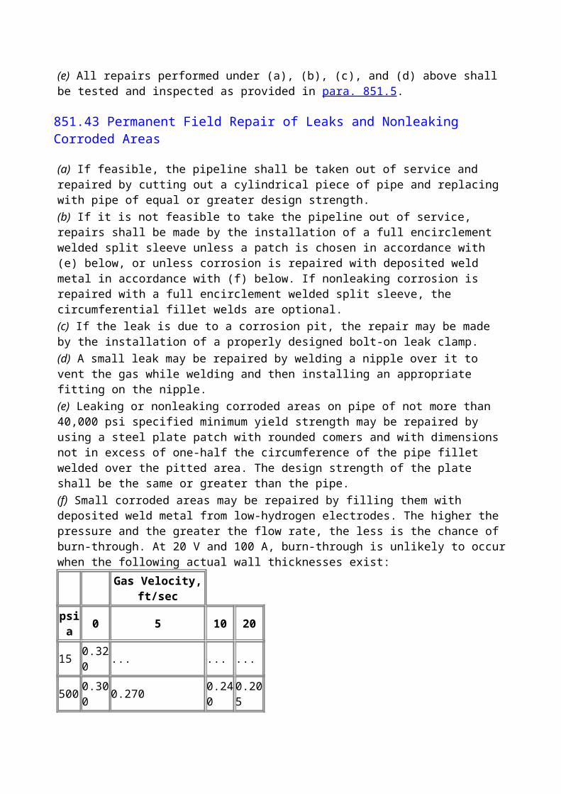
B823.2 Requirements for Qualifications of Procedures and Welders on Piping Systems
B823.22
All procedure and performance qualifications shall be based on destructive mechanical test requirements.
B823.24 Hardness Control.
The hardness of all weld zones including weld metal and heat affected zones on welding qualification test specimens shall meet the hardness requirements for the alloys welded as specified in NACE MR0175. For most common pipe alloys, the maximum allowable hardness is HRC 22. It is the user's responsibility to ensure the welding qualification specimen is metallurgically representative of full-scale pipeline welds.
NOTE: Both macrohardness and microhardness surveys of properly prepared qualification specimens are frequently used to determine the presence of thin HAZ hard zones. A commonly accepted maximum macrohardness limit near the inside surface is 250 HV10.
B824PREHEATING
B824.5 Hydrogen Bake Out of Used Pipe
Pipe that has been used in sour gas service shall be heated for at least 20 min at 400°F (204°C) or higher to drive off any hydrogen in the metal. Heating shall be done just prior to welding. This heating should be in addition to and immediately preceding any preheating specified in the welding procedure for new pipe
B825 STRESS RELIEVING
B825.2
The chemistry of the steel and welding procedure shall be controlled to limit the hardness of the weldment as required by para. B823.24. When the effectiveness of such controls is questionable, consideration shall be given to stress relieving welds in sour gas service. In general, temper bead welding, peening procedures, or low-temperature postweld heat treatment does not provide the equivalent protection from service cracking as does a full thermal stress relief.
B825.6 Stress Relieving Temperature
(a) Stress relieving is normally performed at a temperature of 1,100°F (593°C) for carbon steels and 1,200°F (649°C) for ferritic alloy steels. Other stress relieving procedures may be substituted when properly supported with metallurgical evidence. The exact temperature range shall be stated in the procedure specification.
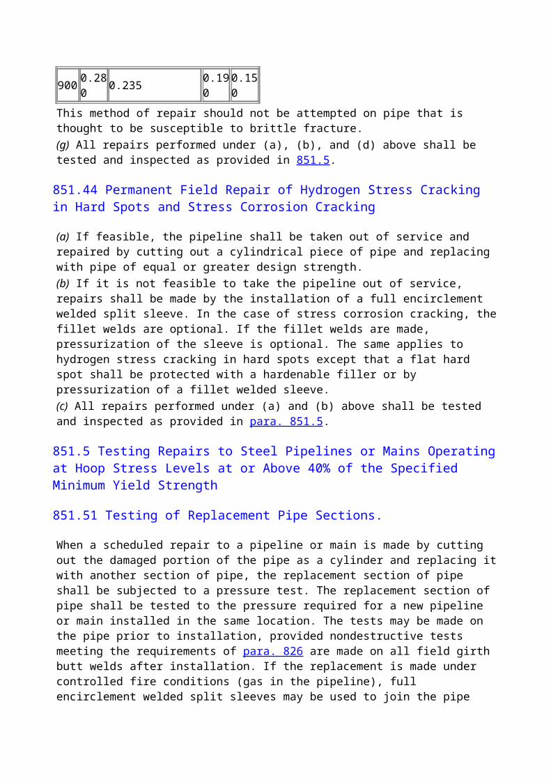
(b) When stress relieving a joint between dissimilar metals having different stress relieving requirements, the material requiring the higher stress relieving temperature shall govern. Special considerations may be required for austenitic and other high alloys.(c) The parts heated shall be brought slowly to the required temperature and held at that temperature for a period of time proportioned on the basis of at least 1 hr/in. (1 hr/25 mm) of pipe wall thickness, but in no case less than hr, and shall be allowed to cool slowly and uniformly.(d) Records. A suitable record of the stress relief cycles shall be provided for each weld stress relieved.(e) Temperature Control. A group of closely spaced welds, such as three welds on a tee, can be controlled and recorded by a single thermocouple
B826 WELDING AND INSPECTION TESTS
B826.2 Inspection and Tests for Quality Control of Welds on Sour Gas Piping Systems
In addition to subparas. 826.2(a) through (f), for sour gas lines in Class 3 or 4 locations, compressor stations, major or navigable river crossings, railroad crossings, and road crossings, 100% of all field welds shall be checked by nondestructive inspection. Nondestructive inspection may be conducted before or after stress relieving..
B830 PIPING SYSTEM COMPONENTS AND FABRICATION DETAILS
In addition to para. 830, all components shall meet the requirements of NACE MR0175 as appropriate.
B831 PIPING SYSTEM COMPONENTS
B831.1 Valves and Pressure Reducing Devices
B831.13
(a) Instruments, instrument tubing, controllers, gauges, and other components that become a part of the pressure containment system shall meet NACE MR0175 requirements.(b) Most copper-based alloys suffer severe corrosion in sour service. Use of such alloys in any components shall be investigated for suitability.
B831.2Flanges
B831.22 Bolting
(h) Bolting exposed to sour gas and denied access to air due to thermal insulation, flange protectors, or certain design features shall meet the requirements of NACE MR0175 as appropriate. Designers should note that bolting meeting NACE MR0175 requirements, such as type ASTM A 193 grade B7M, have derated tensile properties, and the joint design shall be appropriate for such deration. Bolting opened to atmosphere may be conventional ASTM A 193 grade B7 bolting.
B840 DESIGN, INSTALLATION, AND TESTING
B841 STEEL PIPE
B841.1 Steel Piping Systems Design Requirements
B841.11 Steel Pipe Design Formula
(c) Fracture Control. Fracture control should be considered for sour gas service.
B841.114 Design Factors F and Location Classes.
When using Table 841.114A, design factor F of 0.80 shall not be used for sour gas service.
B841.2 Installation of Steel Pipelines and Mains
B841.23 Bends, Elbows, and Miters in Steel Pipelines
B841.231
(f) Bends used in sour gas pipe shall meet the requirements of NACE MR0175 in the as-bent condition Hot bends may be needed to meet NACE MR0175 requirements. The first prototype bend may be needed for testing to ensure hardness requirements of NACE MR0175 and that both toughness and tensile properties are still acceptable. Neither wrinkle bends nor miter bends are permitted for sour gas lines.
B841.24 Pipe Surfaces Requirements Applicable to Pipelines and Mains to Operate at a Hoop Stress of 20% or More of the Specified Minimum Yield Strength
B841.245 Arc Burns.
Additionally, arc burns have been found to cause serious stress concentration in pipelines and in sour gas lines, and shall be prevented or eliminated in all lines.Arc burns may be removed by grinding, chipping, or machining. The resulting cavity shall be thoroughly cleaned and checked for complete removal of damaged material by etching with a 10% solution of ammonium persulfate or a 5% solution of nitric acid in alcohol (nital). If removal of damaged material is complete, the cavity may be merged smoothly into the original contour of the pipe by grinding, provided the remaining wall thickness is within specified limits.
B841.26 Hot Taps.
In addition to para. 841.26 of Chapter IV, it should be noted that hot tapping of sour gas lines presents special health and metallurgical concerns and shall be done only to written operating company approved plans.

B841.27 Precautions to Avoid Explosions of Gas-Air Mixtures or Uncontrolled Fires During Construction Operations
B841.271
In addition to the precautions outlined in para. 841.271 of Chapter IV, it should be noted that welding and cutting on sour gas lines presents special health and metallurgical concerns and shall be done only to written operating company approved plans.
B841.3 Testing After Construction
B841.31 General Provisions.
In addition to para. 841.31 of Chapter IV, it should be noted that testing with sour gas presents special health and metallurgical concerns and shall be done only to written operating company approved plans.
B842 OTHER MATERIALS
B842.1
Materials shall meet the requirements of NACE MR0175 as applicable.
B842.3 Design of Plastic Piping
B842.39 Plastic Pipe and Tubing Joints air Connections
B842.392 Joint Requirements.
Fusion bonded joints in thermoplastic pipe used in sour gas service are acceptable. All cement, adhesive, and fusion bonding joining procedures and joiners shall be qualified to written procedures using destructive test specimens of full scale plastic pipe joints.
B843 COMPRESSOR STATIONS
B843.4 Compressor Station Equipment
B843.41 Gas Treating Facilities
B843.413
All metallic materials in contact with pressurized sour gas shall meet the requirements of NACE MR0175 as applicable.Personal safety equipment should be considered for use at sour gas facilities. Use of appropriate hydrogen sulfide sensors capable of actuating station emergency shutdown systems should be considered.

B844 PIPE-TYPE AND BOTTLE-TYPE HOLDERS
Pipe- and bottle-type holders shall not be used for sour gas. Storage of sour gas is outside the scope of this Code.
B850 ADDITIONAL OPERATING AND MAINTENANCE CONSIDERATIONS AFFECTING THE SAFETY OF SOUR GAS PIPELINES
B850.1
(c) Radius of exposure (ROE) to H2S calculations shall be made using a suitable air dispersion equation such as the Pasquel-Gifford equation given as follows:(1) Each operator shall determine the hydrogen sulfide concentration in the gaseous mixture in the system. Suitable standards are ASTM D 2385, GPA C-1, GPA publication 2265. (2) Radius of Exposure Equations(a) Radius of exposure equation to the 100-ppm level of H2S after dispersal:
(b) Radius of exposure equation to the 500-ppm level of H2S after dispersal:
where
M = mol fraction of hydrogen sulfide in the gaseous mixture
Q = maximum volume determined to be available for escape in cubic feet per day corrected to 14.65 psia and 60°F
X = radius of exposure (ROE) in feet(3) Metric Equations(a) 100-ppm level of H2S after dispersal:
(b) 500-ppm level of H2S after dispersal:
where
M = mol fraction of hydrogen sulfide in the gaseous mixture
Qm = maximum volume determined to be available for escape in cubic meters per day corrected to 1.01 bars and 15.6°C.
Xm = radius of exposure (ROE) in meters
NOTE: The equations assume a 24-hr release. When a pipeline segment can be isolated in less than 24 hr, appropriate reductions in (Q) may be used.
(4) Examples of 100-ppm and 500-ppm ROE for various 24-hr releases and H2S mol fractions are as follows.
100-ppm ROEROE Release H2S
ft, MMSCFD MolX Q (1,000,000) Fraction
1,165 1 0.053,191 5 0.054,924 10 0.057,597 20 0.059,792 30 0.051,798 1 0.14,924 5 0.17,597 10 0.111,723 20 0.115,109 30 0.12,775 1 0.27,597 5 0.211,723 10 0.218,090 20 0.223,315 30 0.2
500-ppm ROEROE Release H2S
ft, MMSCFD MolX Q (1,000,000) Fraction
533 1 0.051,458 5 0.052,250 10 0.053,472 20 0.054,474 30 0.05822 1 0.12,250 5 0.13,472 10 0.15,357 20 0.16,904 30 0.11,268 1 0.23,472 5 0.25,357 10 0.2
8,266 20 0.210,654 30 0.2
B850.4 Essential Features of the Emergency Plan
B850.42 Training Program.
In addition to conventional training, all sour gas operation and maintenance line personnel shall be trained in(a) hazards and characteristics of H2S(b) effect on metal components of the lines and equipment(c) safety precautions(d) operation of safety equipment and life support systems(e) corrective action and shutdown procedures
B851 PIPELINE MAINTENANCE
B851.7
(d) In addition to each sign required in subpara. 851.7(c) of Chapter V, for operations where the 100-ppm radius of exposure is greater than 50 ft (15.2 m), a "POISON GAS" sign shall be installed.All surface facilities shall also be marked with "POISON GAS" signs.
B851.10
When blowing down sour gas lines, consideration shall be given to the use of suitable permanent or temporary flare systems.
B855 CONCENTRATIONS OF PEOPLE IN LOCATION CLASSES 1 AND 2
B855.1
(c) Security. Unattended fixed surface facilities should be protected from public access when located within mile of a residential, commercial, or other inhabited or occupied structure; bus stop; public park; or similarly populated area.(1) The protection should be provided by fencing and locking or removal of valves and instrumentation and plugging of ports, or other similar means.(2) Surface pipeline is not considered a fixed surface facility.(d) Additional control and safety procedures or safety devices should be installed and maintained to prevent the undetected continuing release of hydrogen sulfide if any of the following conditions exist:(1) The 100-ppm radius of exposure is in excess of 50 ft (15.2 m) and includes any part of a public area except a public road.(2) The 500-ppm radius of exposure is greater than 50 ft (15.2 m) and includes any part of a public road.(3) The 100-ppm radius of exposure is greater than 3,000 ft (915 m).
(e) Contingency Plan. Operations subject to subpara. (d) above shall have a written contingency plan prepared and given to state and local emergency response authorities. Plans shall include maps, location of block valves, valve keys, and keys for locks.
B860 CORROSION CONTROL OF SOUR GAS PIPELINES
B861GENERAL
B861.1 Scope
This section contains the minimum additive or substitutive requirements for corrosion control of external and internal corrosion of sour gas piping and components. Where specific provisions are not set forth herein, the provisions of para. 860 of Chapter VI shall apply.
B861.2 Special Considerations
Due to the corrosivity of hydrogen sulfide and the frequent presence of carbon dioxide and salt water, which also are corrosive, special emphasis shall be given to internal corrosion mitigation and monitoring.Also, due to the corrosive and hazardous nature of the sour gas, special consideration shall be given to the selection of the corrosion allowance.
B862 EXTERNAL CORROSION CONTROL
B862.1 New Installations
B862.11 Buried Steel Facilities
B862.113 Cathodic Protection Requirements.
Unless it can be demonstrated by tests or experience that cathodic protection is not needed, all buried or submerged facilities with insulating type coatings, except facilities installed for a limited service life, shall be cathodically protected as soon as feasible following installation, except that minor replacements or extensions shall be protected as covered by para. 862.212.Facilities installed for a limited service life need not be cathodically protected if it can be demonstrated that the facility will not experience corrosion that will cause it to be harmful to the public or environment. Cathodic protection systems shall be designed to protect the buried or submerged system in its entirety.A facility is considered to be cathodically protected when it meets one or more of the criteria established in Appendix K.Use of cathodic protection is encouraged to protect buried sour gas facilities.
B863 INTERNAL CORROSION CONTROL
B863.1 General

Sour gas facilities shall be assumed to be internally corrosive unless proven by experience to be otherwise. Water dewpoint control frequently is used as a corrosion control method. Upset conditions or operational changes may make this control method ineffective. The use of inhibitors is also common.
B863.2 New Installations
New installations should be designed with
(a) suitable dedicated fittings for corrosion inhibitor injection(b) suitable dedicated fittings and valves to insert and retrieve corrosion measuring devices such as probes and coupons
B866 STRESS CORROSION AND OTHER PHENOMENA
B866.1
Sour gas lines, particularly when combined with carbon dioxide and produced salt water can suffer from several corrosion related phenomena:(a) Hydrogen Related Problems. The corrosion reaction in the presence of the sulfide ion permits a high amount of liberated hydrogen atoms to enter the steel. The hydrogen causes many problems that have been given different names:(1) Sulfide stress cracking (SSC) occurs when the alloys are too hard and/or too highly stressed in the presence of corrosion with sour gas. NACE MR0175 outlines all of the acceptable materials combinations to resist this type of cracking.(2) Hydrogen induced cracking (HIC) occurs when hydrogen causes inclusions in the steel to delaminate. Multiple shear cracks then develop to link the delaminations, creating a stair step crack system. Use of HIC resistant materials should be considered for sour gas service.(3) Stress oriented hydrogen induced cracking (SOHIC) is another variant of HIC. SOHIC is HIC enhanced by high-tensile stress.(4) Hydrogen blistering consists of hydrogen atoms diffusing inside the steel to delaminated areas and recombining to form molecules of hydrogen gas. The resulting pressure can create large blisters on either the inside or outside surfaces of the steel.(b) Chloride stress corrosion cracking is caused by chlorides in the produced water. Austenitic stainless steels are particularly prone to this type of cracking. The sulfide ion has a synergistic effect with the chloride ion. The net result is the occurrence of cracking at lower temperatures and at lower chloride concentrations than normally expected. Except for small low stressed parts such as thermowells, use of alloys not resistant to chloride stress cracking above 140°F is discouraged in wet sour gas systems.(c) Microbiologic induced corrosion (MIC). Microbiologic activity can create severe pitting-type corrosion and hydrogen-related cracking in sour gas lines. Use of appropriate biocides and monitoring may be needed.
(99) APPENDIX A REFERENCES
These specifications may be immediately applied to materials purchased for use under this Code and shall be applied to all materials purchased 12 months or later after the date of issuance of the

reference's latest edition, including addenda, if applicable. A component or pipe conforming to an earlier approved material specification edition purchased by the user before the date of issuance of a new edition or addenda may be used, provided the component or pipe is inspected and determined to be satisfactory for the service intended by the user.Standards are incorporated in this Code by reference, and the names and addresses of the sponsoring organizations are shown in this Appendix. It is not practical to refer to a specific edition of each standard throughout the Code text; instead, the latest edition including addenda, if applicable, shall be used unless otherwise noted.An asterisk (*) is used to indicate standards that have been accepted as American National Standards by the American National Standards Institute (ANSI).
*AGA Z223.1, National Fuel Gas Code
Publisher: American Gas Association (AGA), 400 North Capitol Street, NW, Washington, DC 20001
API 5L, Line Pipe
API 6A, Wellhead Equipment
API 6D, Pipeline Valves
API 1104, Standard for Welding Pipelines and Related Facilities
API RP 2A, Recommended Practice for Planing, Designing and Constructing Fixed Offshore Platforms
API RP 5L1, Recommended Practice for Railroad Transportation of Line Pipe
API RP 5L5, Recommended Practice for Marine Transportation of Line Pipe
API RP 5L6, Recommended Practice for Transportation of Line Pipe on Inland Waterways
API RP 5LW, Transportation of Line Pipe on Barges and Marine Vessels
API RP 17B, Recommended Practice for Flexible Pipe
Publisher: American Petroleum Institute (API), 1220 L Street, NW, Washington, DC 20005
*ASME B1.1, Unified Inch Screw Threads
*ASME B1.20.1, Pipe Threads (Except Dryseal)
*ASME B16.1, Cast Iron Pipe Flanges and Flanged Fittings
*ASME B16.5, Steel Pipe Flanges and Flanged Fittings
*ASME B16.9, Factory-Made Wrought Steel Buttwelding Fittings
*ASME B16.11, Forged Steel Fittings, Socket-Welding and Threaded
*ASME B16.20, Ring-Joint Gaskets and Grooves for Steel Pipe Flanges
*ASME B16.24, Bronze Pipe Flanges and Flanged Fittings
*ASME B16.33, Small Manually Operated Metallic Gas Valves in Gas Distribution Systems Whose Maximum Allowable Operating Pressure Does Not Exceed 60 psig or 125 psig
*ASME B16.34, Steel Valves (Flanged and Buttwelding End)
*ASME B16.38, Large Manually Operated Metallic Gas Valves in Gas Distribution Systems, Whose Maximum Allowable Operating Pressure Does Not Exceed 125 psig (8.6 bar, gage)
*ASME B16.40, Manually Operated Thermoplastic Gas Shut-Offs and Valves in Gas Distribution Systems
*ASME B16.42, Ductile Iron Pipe Flanges and Flanged Fittings
*ASME B18.2.1, Square and Hex Bolts and Screws, Including Askew Head Bolts, Hex Cap Screws, and Lag Screws
*ASME B18.2.2, Square and Hex Nuts
ASME B31G, Manual for Determining the Remaining Strength of Corroded Pipelines
*ASME B31.1, Power Piping
*ASME B31.2, Fuel Gas Piping
*ASME B31.3, Chemical Plant and Petroleum Refinery Piping
*ASME B31.4, Liquid Petroleum Transportation Piping System
ASME B36.10M, Welded and Seamless Wrought Steel Pipe
*ASME BPV Code, Section VIII, Pressure Vessels, and Section IX, Welding Qualifications
ASME SI-1, ASME Orientation and Guide for Use of SI (Metric) Units
Publisher: The American Society of Mechanical Engineers (ASME), Three Park Avenue, New York, NY 10016; Order Department: 22 Law Drive, Box 2300, Fairfield, NJ 07007
ASTM A 53, Pipe, Steel, Black and Hot-Dipped, Zinc-Coated Welded and Seamless
ASTM A 105/A 105M, Forgings, Carbon Steel, for Piping Components
ASTM A 106, Seamless Carbon Steel Pipe for High-Temperature Service
ASTM A 120, Pipe, Steel, Black and Hot-Dipped Zinc-Coated (Galvanized) Welded and Seamless for Ordinary Use
ASTM A 134, Electric-Fusion (Arc)-Welded Steel Plate Pipe (Sizes 16 in. and Over)
ASTM A 135, Electric-Resistance-Welded Steel Pipe
ASTM A 139, Electric-Fusion (Arc)-Welded Steel Plate Pipe (Sizes 4 in. and Over)
ASTM A 193/A 193M, Alloy-Steel and Stainless Steel Bolting Materials for High-Temperature Service
ASTM A 194/A 194M, Carbon and Alloy Steel Nuts for Bolts for High-Pressure and High-Temperature Service
ASTM A 211, Spiral-Welded Steel or Iron Pipe
ASTM A 307, Carbon Steel Externally Threaded Standard Fasteners
ASTM A 320/A 320M, Alloy Steel Bolting Materials for Low-Temperature Service
ASTM A 333/A 333M, Seamless and Welded Steel Pipe for Low-Temperature Service
ASTM A 354, Quenched and Tempered Alloy Steel Bolts, Studs, and Other Externally Threaded Fasteners
ASTM A 372/A 372M, Carbon and Alloy Steel Forgings for Thin-Walled Pressure Vessels
ASTM A 381, Metal-Arc-Welded Steel Pipe for Use With High-Pressure Transmission Systems
ASTM A 395, Ferritic Ductile Iron Pressure-Retaining Castings for Use at Elevated Temperatures
ASTM A 449, Quenched and Tempered Steel Bolts and Studs
ASTM A 671, Electric-Fusion-Welded Steel Pipe for Atmospheric and Lower Temperatures
ASTM A 672, Electric-Fusion-Welded Steel Pipe for High-Pressure Service at Moderate Temperatures
ASTM B 88, Seamless Copper Water Tube
ASTM D 696, Test for Coefficient of Linear Thermal Expansion of Plastics
ASTM D 2513, Thermoplastic Gas Pressure Pipe, Tubing, and Fittings
ASTM D 2517, Reinforced Epoxy Resin Gas Pressure Pipe and Fittings
ASTM D 2837, Hydrostatic Design Basis for Thermoplastic Pipe Materials, Obtaining
ASTM E 380, Metric Practice Publisher: American Society for Testing and Materials (ASTM), 100 Barr Harbor Drive, West Conshochocken, PA 19428
*AWS A3.0 Welding Terms and Definitions
AWS D3.6 Underwater Welding, Type "0" Welds
Publisher: American Welding Society (AWS), 550 NW LeJeune Road, Miami, FL 33135
*AWWA A21.14, Ductile-Iron Fittings 3-Inch Through 24-Inch for Gas
*AWWA A21.52, Ductile-Iron Pipe, Centrifugally Cast, in Metal Molds or Sand-Lined Molds for Gas
AWWA C101, Thickness Design of Cast Iron Pipe9
*AWWA C111/A21.11, Rubber Gasket Joints for Ductile-Iron and Gray-Iron Pressure Pipe and Fittings
*AWWA C150/A21.50, Thickness Design of Ductile-Iron Pipe
Publisher: American Water Works Association (AWWA), 6666 West Quincy Avenue, Denver, CO 80235
EPRI EL-3106 (Also published as AGA-L51418, Power Line-Induced AC Potential on Natural Gas Pipelines for Complex Rights-of-Way Configurations)
Publisher: Electric Power Research Institute (EPRI), 3412 Hillview Avenue, P.O. Box 10412, Palo Alto, CA 94304
MSS SP-6, Standard Finishes for Contact Faces of Pipe Flanges and Connecting End Flanges of Valves and Fittings
MSS SP-25, Standard Marking System for Valves, Fittings, Flanges, and Unions
MSS SP-44, Steel Pipe Line Flanges
MSS SP-70, Cast Iron Gate Valves, Flanged and Threaded Ends
MSS SP-71, Cast Iron Swing Check Valves, Flanged and Threaded Ends
MSS SP-75, Specification for High Test Wrought Welding Fittings
MSS SP-78, Cast Iron Plug Valves
Publisher: Manufacturers Standardization Society of the Valve and Fittings Industry (MSS), 127 Park Street, NE, Vienna, VA 22180
NACE MR0175, Sulfide Stress Cracking Resistant-Metallic Materials for Oilfield Equipment
NACE RP0169, Control of External Corrosion on Underground or Submerged Metallic Piping Systems
NACE RP0275, Application of Organic Coatings to the External Surface of Steel Pipe for Underground Service
NACE RP0675, Control of External Corrosion on Off-shore Steel Pipelines
NACE RP0177, Mitigation of Alternating Current and Lightning Effects on Metallic Structures and Corrosion Control Systems
NACE Corrosion Data Survey10
Publisher: National Association of Corrosion Engineers (NACE International), P.O. Box 218340, Houston, TX 77218
*NFPA 10, Portable Fire Extinguishers
*NFPA 30, Flammable and Combustible Liquids Code
*NFPA 58, Liquefied Petroleum Gases, Storage and Handling
*NFPA 59, Liquefied Petroleum Gases at Utility Gas Plants
*NFPA 70, National Electrical Code
*NFPA 220, Types of Building Construction Publisher: National Fire Protection Association (NFPA) 1 Batterymarch Park, Quincy, MA 02269
(99) APPENDIX B NUMBERS AND SUBJECTS OF STANDARDS AND SPECIFICATIONS THAT APPEAR IN APPENDIX A
The information in this Appendix has been incorporated into Appendix A.
APPENDIX C PUBLICATIONS THAT DO NOT APPEAR IN THE CODE OR APPENDIX A
API 5B, Specification for Threading, Gaging, and Thread Inspection of Casing, Tubing, and Line Pipe Thread
API 5LU, Specification for Ultra High Test Heat Treated Line Pipe11
API 5LE, Specification for Polyethylene Line Pipe
API 5LP, Specification for Thermoplastic Line Pipe
API 5LR, Specification for Reinforced Thermosetting Resin Line Pipe
API RP 5L4, Recommended Practice for Care and Use of Reinforced Thermosetting Resin Line Pipe
API RP 1107, Recommended Pipeline Maintenance Welding Practices
Publisher: American Petroleum Institute (API), 1220 L Street, NW, Washington, DC 20005
ASME B1.20.3, Dryseal Pipe Threads
ASME B16.3, Malleable Iron Threaded Fittings
ASME B16.4, Cast Iron Threaded Fittings
ASME B16.14, Ferrous Pipe Plugs, Bushings, and Locknuts With Pipe Threads
ASME B16.15, Cast Bronze Threaded Fittings
ASME B16.18, Cast Copper Alloy Solder Joint Pressure Fittings
ASME B16.22, Wrought Copper and Copper Alloy Solder-Joint Pressure Fittings
ASME B16.25, Buttwelding Ends
ASME B36.10M, Welded and Seamless Wrought Steel Pipe
Publisher: The American Society of Mechanical Engineers (ASME), Three Park Avenue, New York, NY 10016; Order Department: 22 Law Drive, Box 2300, Fairfield, NJ 07007
ASTM A 6, Rolled Steel Plates, Shapes, Sheet Piling, and Bars for Structural Use
ASTM A 20, Steel Plates for Pressure Vessels
ASTM A 29, Steel Bars, Carbon and Alloy, Hot-Rolled and Cold-Finished
ASTM A 36, Structural Steel
ASTM A 47, Malleable Iron Castings
ASTM A 48, Gray Iron Castings
ASTM A 125, Heat-Treated Steel Helical Springs
ASTM A 126, Gray Iron Castings for Valves, Flanges and Pipe Fittings
ASTM A 155, Electric-Fusion Welded Steel Pipe for High-Pressure Service
ASTM A 181, Forgings, Carbon Steel for General Purpose Piping
ASTM A 182, Forged or Rolled Alloy Steel Pipe Flanges, Forged Fittings, and Valves and Parts for High-Temperature Service
ASTM A 197, Cupola Malleable Iron
ASTM A 216, Carbon-Steel Castings Suitable for Fusion Welding for High-Temperature Service
ASTM A 217, Martensitic Stainless Steel and Alloy Steel Castings for Pressure-Containing Parts Suitable for High-Temperature Service
ASTM A 225, Pressure Vessel Plates, Alloy Steel, Manganese-Vanadium
ASTM A 234, Piping Fittings of Wrought Carbon Steel and Alloy Steel for Moderate and Elevated Temperatures
ASTM A 242, High-Strength Low Alloy Structural Steel
ASTM A 283, Low and Intermediate Tensile Strength Carbon Steel Plates, Shapes, and Bars
ASTM A 285, Pressure Vessel Plates, Carbon Steel, Low- and Intermediate-Tensile Strength
ASTM A 350, Forgings, Carbon and Low-Alloy Steel Requiring Notch Toughness Testing for Piping Components
ASTM A 377, Cast Iron and Ductile Iron Pressure Pipe
ASTM A 420, Piping Fittings of Wrought Carbon Steel and Alloy Steel for Low-Temperature Service
ASTM A 441, High-Strength Low-Alloy Structural Manganese Vanadium Steel
ASTM A 442, Pressure Vessel Plates, Carbon Steel, Improved Transition Properties
ASTM A 487, Steel Castings Suitable for Pressure Service
ASTM A 502, Steel Structural Rivets
ASTM A 515, Pressure Vessel Plates, Carbon Steel for Intermediate and Higher Temperature Service
ASTM A 516, Pressure Vessel Plates, Carbon Steel, for Moderate- and Lower-Temperature Service
ASTM A 539, Electric-Resistance-Welded Coiled Steel Tubing for Gas and Fuel Oil Lines
ASTM A 575, Merchant Quality Hot Rolled Carbon Steel Bars
ASTM A 576, Steel Bars, Carbon, Hot Rolled, Special Quality
ASTM A 691, Carbon and Alloy Steel Pipe, Electric-Fusion-Welded for High-Pressure Service at High Temperatures
ASTM A 694, Forgings, Carbon and Alloy Steel for Pipe Flanges, Fittings, Valves and Parts for High-Pressure Transmission Service
ASTM B 21, Naval Brass Rod, Bar, and Shapes
ASTM B 42, Seamless Copper Pipe, Standard Sizes
ASTM B 43, Seamless Red Brass Pipe
ASTM B 61, Steam or Valve Bronze Castings
ASTM B 62, Composition Bronze or Ounce Metal Castings
ASTM B 68, Seamless Copper Tube, Bright Annealed
ASTM B 75, Seamless Copper Tube
ASTM B 249, Wrought Copper and Copper-Alloy Rod, Bar, and Shapes
ASTM B 251, General Requirements for Wrought Seamless Copper and Copper-Alloy Tube (Metric)
ASTM B 584, Copper Alloy Sand Castings for General Applications
Publisher: American Society for Testing and Materials (ASTM), 100 Barr Harbor Drive, West Conshohocken, PA 19428
AWWA C207-55, Steel Pipe Flanges
Publisher: American Water Works Association (AWWA), 6666 West Quincy Avenue, Denver, CO 80235
MSS SP-55, Quality Standard for Steel Castings - Visual Method
MSS SP-61, Pressure Testing of Steel Valves
Publisher: Manufacturers Standardization Society of the Valve and Fittings Industry (MSS), 127 Park Street, NE, Vienna, CA 22180
NACE MR0175, Sulfide Stress Cracking Resistant Metallic Material for Oil Field Equipment
Publisher: National Association of Corrosion Engineers (NACE International), P.O. Box 218340, Houston, TX 77218
NFPA 59A, Liquefied Natural Gas, Production, Storage, and Handling of
Publisher: National Fire Protection Association (NFPA), 1 Batterymarch Park, Quincy, MA 02269
APPENDIX D SPECIFIED MINIMUM YIELD STRENGTH FOR STEEL PIPE COMMONLY USED IN PIPING SYSTEMS12
(99) APPENDIX E FLEXIBILITY AND STRESS INTENSIFICATION FACTORS
(99) APPENDIX F EXTRUDED HEADERS AND WELDED BRANCH CONNECTIONS13
F1 EXTRUDED HEADERS
Definitions and limitations applicable to Figs. F1 through F4 are as follows:D = outside diameter of run
Dc = corroded internal diameter of run
Do = corroded internal diameter of extruded outlet measured at the level of the outside surface of run
L = height of the reinforcement zone
Tb = actual thickness of branch wall not including corrosion allowance
Tr = actual thickness of the run wall, not including the corrosion allowance
To = corroded finished thickness of extruded outlet measured at a height equal to ro above the outside surface of the run
d = outside diameter of branch pipe
dc = corroded internal diameter of branch pipe
ho = height of the extruded lip. This must be equal to or greater than ro, except as shown in limitation (b) of ro below.
r1 = half width of reinforcement zone (equal to Do)
ro =
radius of curvature of external contoured portion of outlet measured in the plane containing the axes of the run and branch. This is subject to the following limitations: (a) Minimum Radius. This dimension shall not be less than 0.05d, except that on branch diameters larger than 30 in., it need not exceed 1.50 in. (b) Maximum Radius. For outlet pipe sizes NPS 6 and larger, this dimension shall not exceed 0.10d + 0.50 in. For outlet pipe sizes less than NPS 8, this dimension shall not be greater than 1.25 in. (c) When the external contour contains more than one radius, the radius on any arc sector of approximately 45 deg shall meet the requirements of (a) and (b) above. (d) Machining shall not be employed to meet the above requirements.
tb = required thickness of branch pipe according to the steel pipe design formula of para. 841.11, but not including any thickness for corrosion
tr = required thickness of the run according to the steel pipe design formula para. 841.11, but not including any allowance for corrosion or under-thickness tolerance
F2 EXAMPLES ILLUSTRATING THE APPLICATION OF THE RULES FOR REINFORCEMENT OF WELDED BRANCH CONNECTIONS
F2.1 Example 1
An NPS 8 outlet is welded to an NPS 24 header. The header material is API 5LX 46 with a 0.312-in. wall. The outlet is API 5L Grade B (Seamless) Schedule 40 with a 0.322-in. wall. The working pressure is 650 psig. The fabrication is in Class Location 1. Using para. 841.1, the joint efficiency is 1.00. The temperature is 100°F. Design factors F = 0.60, E = 1.00, and T = 1.00. For dimensions,
see Fig. F6.
F2.11Header.
Nominal wall thickness required:
Excess thickness in header wall:
F2.12 Outlet.
Nominal wall thickness required:
Excess thickness in outlet wall:
F2.13 Reinforcement Required
F2.14 Reinforcement Provided by Header
F2.15 Effective Area in Outlet
This must be multiplied by 35,000/46,000. [See para. 831.41(f).]
Required area:
Use a reinforced plate that is 0.250 in. thick (minimum practicable) × 15.5 in. in diameter.
Fillet welds (assuming two -in. welds each side):
F2.2 Example 2
An NPS 16 outlet is welded to an NPS 24 header. The header material is API 5LX 46 with a 0.312-in. wall. The outlet is API 51, Grade B (Seamless) Schedule 20 with a 0.312-in. wall. The working pressure is 650 psig. The fabrication is in Class Location 1. By para. 831.42, the reinforcement must be of the complete encirclement type. Using para. 841.1, the joint efficiency is 1.00. The temperature is 100°F. Design factors F = 0.60, E = 1.00, and T = 1.00. For dimensions, see Fig. F7.
F2.21Header.
Nominal wall thickness required:
Excess thickness in header wall:
F2.22Outlet.
Nominal wall thickness required:
Excess thickness in outlet wall:
F2.23 Reinforcement Required
F2.24 Reinforcement Provided
F2.25 Effective Area in Outlet
or
This must be multiplied by 35,000/46,000. [See para. 831.4(f).]
Required area:
Approximate required thickness of reinforcement:
Use a 0.312-in. plate minimum required length (neglecting welds):
Use a plate that is 29 in. long:
Two -in. welds to outlet:
The use of end welds is optional. See Fig. I3.
(99) APPENDIX G TESTING OF WELDERS LIMITED TO WORK ON LINES OPERATING AT HOOP STRESSES OF LESS THAN 20% OF THE SPECIFIED MINIMUM YIELD STRENGTH14
(a) An initial test shall qualify a welder for work. Thereafter, the welder's work shall be checked either by requalification at 1-year intervals or by cutting out and testing production work at least every 6 months.(b) The test may be made on pipe of any diameter 12 in. or smaller. The test weld shall be made with the pipe in a horizontal fixed position so that the test weld includes at least one section of overhead position welding.(c) The beveling, root opening, and other details must conform to the procedure specification under which the welder is qualified.(d) The test weld shall be cut into four coupons and subjected to the root bend test. If as a result of this test, a crack develops in the weld material or between the weld and base metal more than in.
long in any direction, this shall be cause for rejection. Cracks occurring on the corner of the specimen during testing shall not be considered. If not more than one coupon is rejected, the weld is to be considered acceptable.(e) Welders who are to make welded service line connections to mains shall be required to pass the following tests satisfactorily:(1) Weld a service line connection fitting to a pipe section having the same diameter as a typical main. This weld shall be made in the same position as this type of weld is made in the field.(2) The weld shall be tested by attempting to break the fitting off the run pipe by any available means (knocking it off).A sample shall be rejected if the broken weld at the junction of the fitting and run pipe shows incomplete fusion, overlap, or poor penetration.(f) For the periodic checking of welders who work on small service lines only (2 in. or smaller in diameter), the following special field test may be employed. This test should not be used as a substitute for the original qualifying test.Two sample welds made by the welder under test shall be taken from steel service line. Each sample shall be cut 8 in. long with the weld located approximately in the center. One sample shall have the ends flattened and the entire joint subjected to the tensile strength test. Failure must be in the parent metal and not adjacent to or in the weld metal to be acceptable. The second sample shall be centered in the guided bend testing machine and bent to the contour of the die for a distance of 2 in. on each side of the weld. The sample to be acceptable must show no breaks or cracks after removal from the bending machine.When a tensile strength testing machine is not available, two bend test samples will be acceptable in lieu of one tension and one bending test.(g) Tests for Copper Joints. Personnel who are to work on copper piping should pass the following test satisfactorily.A brazed or soldered copper bell joint should be made on any size of copper pipe used, with the axis of the pipe stationary in the horizontal position. The joint so welded is to be sawed open longitudinally at the top of the pipe (the top being the uppermost point on the circumstance at time joint is brazed). The joint should be spread apart for examination. The bell end of the joint must be completely bonded. The spigot end of the joint must give evidence that the brazing alloy has reached at least 75% of the total area of the telescoped surfaces. At least 50% of the length a the top of the joint must be joined.(h) Records shall be kept of the original tests and all subsequent tests conducted on the work of each welder.
APPENDIX H FLATTENING TEST FOR PIPE15
(a) The flattening test shall be made on standard weight and extra strong pipe over NPS 2. It shall not be required for double extra strong pipe.(b) For a lap-welded and buttwelded pipe, the test section shall be 4 in. to 6 in. in length, and the weld shall be located 45 deg from the line of direction of the applied force.(c) For electric-resistance welded pipe, both crop ends from each length of pipe shall be flattened between parallel plates with the weld at the point of maximum bending until the weld at the point of maximum bending until the opposite walls of the pipe meet. No opening in the weld shall take place until the distance between the plates is less than two-thirds of the original outside diameter of the pipe. No cracks or breaks in the metal other than in the weld shall occur until the distance between the plates is less than one-third of the original outside diameter of the pipe, but in no case less than five times the thickness of the pipe wall. Evidence of lamination or burnt material shall
not develop during the entire flattening process, and the weld shall not show injurious defects.(d) For seamless pipe the test section shall not be less than 2 in. in length.(e) The test shall consist of flattening a section of pipe between parallel plates until the opposite walls meet. For welded pipe, no opening in the weld shall take place until the distance between the plates in less than three-fourths of the original outside diameter for buttwelded pipe, and two-thirds of the outside diameter for lap-welded and electric-resistance welded pipes. No cracks or breaks in the metal other than in the weld shall occur until the distance between the plates is less than three-fifths of the outside diameter for buttwelded pipe, and one-third of the outside diameter for lapwelded and electric-resistance welded (grades A and B) pipes. For seamless (grades A and B) pipe, no breaks or cracks in the metal shall occur until the distance between the plates is less than that shown below:
where
D = actual outside diameter of pipes, in. (2.375 in. nominal)
H = distance between flattening plates, in.
e = deformation per unit length (constant for a given grade of steel, 0.09 for grade A and 0.07 for grade B)
t = nominal wall thickness of pipe, in.
APPENDIX I END PREPARATIONS FOR BUTTWELDING
I1 EXPLANATORY NOTES
I1.1General
This Appendix applies to end preparation for butt-welding sections having unequal thicknesses and unequal specified minimum yield strengths.(a) The sketches in Fig. I5 illustrate acceptable preparations for joining pipe ends by buttwelding for materials having unequal wall thicknesses and/or with unequal strengths (specified minimum yield strength).(b) The thickness of the sections to be joined beyond the joint design area shall comply with the design requirements of this Code.(c) When the specified minimum yield strengths of the sections to be joined are unequal, the deposited weld metal shall have mechanical properties at least equal to those of the section having the higher strength.(d) The transition between ends of unequal thickness may be accomplished by taper or welding as illustrated or by means of a prefabricated transition ring.(e) Sharp notches or grooves at the edge of the weld where it joins a slanted surface shall be avoided.(f) For joining unequal thicknesses of equal specified minimum yield strengths, the rules given herein apply, except there is no minimum angle limit to the taper.(g) The maximum thickness, tD, for design purposes shall not be greater than 1.5t.
I1.2 Unequal Internal Diameters
(a) For piping to operate at hoop stresses of less than 20% of specified minimum yield strength, if the nominal wall thicknesses of the adjoining ends do not vary more than in., no special treatment is necessary provided adequate penetration and bond is accomplished in welding. If the offset is greater than in., the following paragraphs will apply.(b) For Stress Levels 20% or More of the Specified Minimum Yield Strength(1) If the nominal wall thickness of the adjoining ends do not vary more than3/32in., no special treatment is necessary, provided full penetration and bond is accomplished in welding. See sketch (a) of Fig. I5.(2) Where the nominal internal offset is greater than3/32in. and there is no access to the inside of the pipe for welding, the transition must be made by a taper cut on the inside end of the thicker section. See sketch (b) of Fig. I5. The taper angle shall not be greater than 30 deg nor less than 14 deg.(3) Where the nominal internal offset is more than3/32in. but does not exceed one-half the thinner section, and there is access to the inside of the pipe for welding, the transition may be made with a tapered weld as shown in sketch (c) of Fig. I5. The land on the thicker section must be equal to the offset plus the land on abutting section.(4) Where the nominal internal offset is more than one-half the thinner section and there is access to the inside of the pipe for welding, the transition may be made with a taper cut on the inside end of the thicker section as shown in sketch (b) of Fig. I5, or by a combination taper weld to one-half the thinner section and a taper cut from that point as shown in sketch (d) of Fig. I5.
I1.3 Unequal External Diameters
(a) Where the external offset does not exceed one-half the thinner section, the transition may be made by welding as shown by sketch (e) of Fig. I5, provided the angle of rise of the weld surface does not exceed 30 deg and both bevel edges are properly fused.(b) Where there is an external offset exceeding one-half the thinner section, that portion of the offset over t shall be tapered as shown in sketch (f) of Fig. I5.
I1.4 Unequal Internal and External Diameters
Where there is both an internal and an external offset, the joint design shall be a combination of sketches (a) through (f) of Fig. I5, i.e., sketch (g). Particular attention must be paid to proper alignment under these conditions.
APPENDIX J COMMONLY USED CONVERSION FACTORS16
APPENDIX K CRITERIA FOR CATHODIC PROTECTION
Reprinted with permission from the National Association of Corrosion Engineers' NACE Standard RP0169, Section 6. Asterisk (*) denotes word change from NACE text.
6.1 Introduction
6.1.1
The purpose of this Appendix* is to list criteria for cathodic protection which, when complied with either separately or collectively, will indicate that adequate cathodic protection of a metallic system in its electrolyte has been achieved.
6.2 General
6.2.1
The objective of using cathodic protection is to control the corrosion of metallic surfaces in contact with electrolyte.
6.2.2
The selection of a particular criterion for achieving the objective in 6.2.1 depends, in part, upon past experience with similar structures and environments wherein the criterion has been used successfully.
6.2.3
The criteria in Section 6.3 have been developed through laboratory experiment or empirically determined by evaluating data obtained from successfully operated cathodic protection systems. It is not intended that the operating company* be limited to these criteria if it can be demonstrated by other means that the control of corrosion has been achieved.
6.2.4
Voltage measurements on pipelines are to be made with the reference electrode located on the electrolyte surface as close as feasible to the structure surface being investigated. Consideration shall be given to voltage (IR) drops other than those across the structure-electrolyte boundary, the presence of dissimilar metals, and the influence of other structures for valid interpretation of voltage measurements.*
6.2.5
No one criterion for evaluating the effectiveness of cathodic protection has proven to be satisfactory for all conditions. Often a combination of criteria is needed for a single structure.
6.3 Criteria
6.3.1 Steel and Cast Iron Structures
6.3.1.1
A negative (cathodic) voltage of at least 0.85 volt as measured between the structure surface and a saturated copper-copper sulfate reference electrode contacting the electrolyte. Determination of this voltage is to be made with the protective current applied.
6.3.1.2
A minimum negative (cathodic) voltage shift of 300 millivolts, produced by the application of protective current. The voltage shift is measured between the structure surface and a saturated copper-copper sulfate reference electrode contacting the electrolyte. This criterion of voltage shift applies to structures not in contact with dissimilar metals.
6.3.1.3
A minimum negative (cathodic) polarization voltage shift of 100 millivolts measured between the structure surface and a saturated copper-copper sulfate reference electrode contacting the electrolyte. This polarization voltage shift is to be determined by interrupting the protective current
and measuring the polarization decay. When the current is initially interrupted, an immediate voltage shift will occur. The voltage reading after the immediate shift, shall be used as the base reading from which to measure polarization decay.
6.3.1.4
A structure-to-electrolyte voltage at least as negative (cathodic) as that originally established at the beginning of the Tafel segment of the E-log-I curve. This structure-to-electrolyte voltage shall be measured between the structure surface and a saturated copper-copper sulfate reference electrode contacting the electrolyte at the same location where voltage measurements were taken to obtain the E-log-I-curve.
6.3.1.5
A net protective current from the electrolyte into the structure surface as measured by an earth current technique applied at predetermined current discharge (anodic) points of the structure.
6.3.2 Aluminum Structures
6.3.2.1
A minimum negative (cathodic) voltage shift of 150 millivolts, produced by the application of protective current. The voltage shift is measured between the structure surface and a saturated copper-copper sulfate reference electrode contacting the electrolyte. See precautionary notes in 6.3.2.3 and 6.3.2.4.
6.3.2.2
A minimum negative (cathodic) polarization voltage shift of 100 millivolts, measured between the structure surface and a saturated copper-copper sulfate reference electrode contacting the electrolyte. This polarization voltage shift is to be determined by interrupting the protective current and measuring polarization decay. When the current is initially interrupted, an immediate voltage shift will occur. The voltage reading after the immediate shift shall be used as the base reading from which to measure polarization decay. See precautionary notes in 6.3.2.3 and 6.3.2.4.
6.3.2.3
PRECAUTIONARY NOTE - Excessive Voltages: Notwithstanding the alternative minimum criteria in 6.3.2.1 and 6.3.2.2, aluminum, if cathodically protected at voltages in excess of 1.20 volts measured between the structure surface and a saturated copper-copper sulfate reference electrode contacting the electrolyte and compensated for the voltage (IR) drops other than those across the structure-electrolyte boundary, may suffer corrosion resulting from the buildup of alkali on the metal surface. A voltage in excess of 1.20 volts should not be used unless previous test results indicate no appreciable corrosion will occur in the particular environment.
6.3.2.4
PRECAUTIONARY NOTE - Alkaline Soil Conditions: Since aluminum may suffer from corrosion under high pH conditions and since application of cathodic protection tends to increase the pH at the metal surface, careful investigation or testing should be made before applying cathodic protection to stop pitting attack on aluminum structures in environments with a natural pH in excess of 8.0.
6.3.3 Copper Structures
6.3.3.1
A minimum negative (cathodic) polarization voltage shift of 100 millivolts measured between the structure surface and saturated copper-copper sulfate reference electrode in the electrolyte. This polarization voltage shift is to be determined by interrupting the protective current and measuring the polarization decay. When the current is initially interrupted, immediate voltage shift will occur. The voltage reading after the immediate shift shall be used as the base reading from which to measure polarization decay.
6.3.4 Dissimilar Metal Structure
6.3.4.1
A negative (cathodic) voltage, between all structure surfaces and a saturated copper-copper sulfate reference electrode contacting the electrolyte, equal to that required for the most anodic metal should be maintained. If amphoteric structures are involved that could be damaged by high alkalinity (see precautionary notes in 6.3.2.3 and 6.3.2.4), they should be electrically isolated with insulating flanges or the equivalent.
6.4 Alternative Reference Electrodes
6.4.1
Other standard reference electrodes may be substituted for the saturated copper-copper sulfate reference electrodes. Two commonly used electrodes are listed below along with their voltage equivalent to -0.85 volt referred to saturated copper-copper sulfate reference electrode:
6.4.1.1
Saturated KCI calomel reference electrode: -0.78 volt.
6.4.1.2
Silver-silver chloride reference electro used in sea water: -0.80 volt.
6.4.2
In addition to these standard reference electrodes, an alternative metallic material or structure may be used in place of the saturated copper-copper sulfate reference electrode if the stability of its electrode potential is assured and if its voltage equivalent referred to a saturated copper-copper sulfate reference electrode is established.
6.5 Special Considerations
6.5.1
Special cases, such as stray currents and stray electrical gradients, may exist which require the use of criteria different from those listed above. Measurements of current loss and gain on the structure and current tracing in the electrolyte have been useful in such cases.
6.5.2
Abnormal conditions sometimes exist where protection is ineffective or only partially effective. Such conditions may include elevated temperatures, disbonded coatings, shielding, bacterial attack, and unusual contaminants in the electrolyte.
APPENDIX L DETERMINATION OF REMAINING STRENGTH OF CORRODED PIPE17
For steel pipelines operating at or above 40% of the specified minimum yield strength, the remaining strength of corroded pipe may be determined by the following analysis.(a) Determine depth of corrosion, d. (See Fig. L1.) If d is less than 10% of t, the nominal wall thickness, no reduction in MAOP need be considered. If d is greater than 80% of t, consideration should be given to removing the affected segment from service.(b) Determine the effective length, L, of corrosion along the longitudinal axis.(c) Calculate the nondimensional factor, A:
where
D = nominal outside diameter of the pipe, in.(d) For values of A less than or equal to 4.0,
where
P = the greater of either the design pressure (excluding the joint factor) or the established MAOP, psig
P = the safe maximum pressure for the corroded area, psig
except that P may not exceed P.
(e) For values of A greater than 4.0,
except that P may not exceed P.
(f) If the established MAOP is equal to or less than P , the corroded region may remain in service at the MAOP if protected from further corrosion. If it is greater than P , the MAOP should be reduced so that P is not exceeded, or the corroded region should be repaired by one of the methods prescribed in para. 851.4 or replaced.
(99) APPENDIX M GAS LEAKAGE CONTROL CRITERIA18
M1 SCOPE
This Appendix provides criteria for detection, grading, and control of gas leakage.
M2 DEFINITIONS (APPLICABLE TO THIS APPENDIX ONLY) bar hole: hole that is made in the soil or paving for the specific purpose of testing the subsurface atmosphere with a combustible gas indicator (CGI).
building: any structure that is normally or occasionally entered by humans for business, residential, or other purposes, and in which gas could accumulate.
combustible gas indicator (CGI): a device capable of detecting and measuring gas concentrations of the atmosphere.
confined space: any subsurface structure, such as vaults, catch basins, or manholes, of sufficient size to accommodate a person, and in which gas could accumulate.
followup inspection: an inspection performed after a repair has been completed to determine the effectiveness of the repair.
gas associated substructure: a device or facility utilized by a gas company such as a valve box, vault, test box, or vented casing pipe, which is not intended for storing, transmitting, or distributing gas.
LEL: the lower explosive limit of the gas being transported.
prompt action: consists of dispatching qualified personnel without delay for evaluating and, where necessary, abating the existing or probable hazard.
reading: repeatable deviation on a CGI or equivalent instrument, expressed in LEL. Where the reading is in an unvented confined space, consideration should be given to the rate of dissipation when the space is ventilated and the rate of accumulation when the space is resealed.
small substructures (other than gas associated substructures): any subsurface structures that are of insufficient size to accommodate a person, such as telephone and electrical ducts and conduit or nongas-associated valve and meter boxes, and in which gas could accumulate or migrate.
tunnel: a subsurface passageway large enough for a person to enter and in which gas could accumulate.
M3 LEAKAGE SURVEY AND TEST METHODS
(a) The following gas leakage surveys and test methods may be employed, as applicable, singly or in combination, in accordance with written procedures:(1) surface gas detection survey(2) subsurface gas detector survey (including bar hole surveys)(3) vegetation survey(4) pressure drop test(5) bubble leakage test(6) ultrasonic leakage testOther survey and test methods may be employed if they are deemed appropriate and are conducted in accordance with procedures that have been tested and proven to be at least equal to the methods listed in this section.(b) Surface Gas Detection Survey(1) Definition. This survey is a continuous sampling of the atmosphere at or near ground level for buried gas facilities and adjacent to above-ground gas facilities with a gas detector system capable of detecting a concentration of 50 ppm of gas in air at any sampling point.(2) Procedure. Equipment used to perform these surveys may be portable or mobile. For buried piping, sampling of the atmosphere shall take place, where practical, at no more than 2 in. above the ground surface. In areas where the piping is under pavement, samplings shall also be at curb line(s), available ground surface openings (such as manholes, catch basins, sewer, power, and telephone duct openings, fire and traffic signal boxes, or cracks in the pavement or sidewalk), or other interfaces where the venting of gas is likely to occur. Sampling shall be adjacent to the exposed piping.(3) Utilization. The use of this survey method may be limited by adverse conditions (such as excessive wind, excessive soil moisture, or surface sealing by ice or water).
The survey shall be conducted at speeds slow enough to allow an adequate sample to be continuously obtained by placement of equipment intakes over the most logical venting locations, giving consideration to the location of gas facilities and any adverse conditions that might exist.(c) Subsurface Gas Detection Survey(1) Definition. This survey is a sampling of the subsurface atmosphere with a combustible gas indicator (CGI) or other device capable of detecting 0.5% gas in air at the sample point.(2) Procedure. The survey shall be conducted by performing tests with a CGI in a series of available openings (confined spaces and small substructures) and/ or bar holes over, or adjacent to, the gas facility. The location of the gas facility and its proximity to buildings and other structures shall be considered in the spacing of the sample points. Sampling points shall be as close as possible to the main or pipeline, and never further than 15 ft laterally from the facility. Along the route of the main or pipeline, sampling points shall be placed at twice the distance between the pipeline and the nearest building wall, or at 30 ft, whichever is shorter, but in no case need the spacing be less than 10 ft. The sampling pattern shall include sample points adjacent to service taps, street intersections, and known branch connections as well as sampling points over or adjacent to buried service lines at the building wall.(3) Utilization(a) Good judgment shall be used to determine when available openings (such as manholes, vaults, or valve boxes) are sufficient to provide an adequate survey. When necessary, additional sample points (bar holes) shall be made.(b) Sampling points shall be of sufficient depth to sample directly within the subsurface or substructure atmosphere.(d) Vegetation Survey(1) Definition. This survey uses visual observations to detect abnormal or unusual indications in vegetation.(2) Procedure. All visual indications shall be evaluated using a combustible gas indicator (CGI). Personnel performing these surveys shall have good all-around visibility of the area being surveyed, and their speed of travel shall be determined by taking into consideration the following:(a) system layout(b) amount and type of vegetation(c) visibility conditions (such as lighting, reflected light, distortions, terrain, or obstructions)(3) Utilization(a) This survey method shall be limited to areas where adequate vegetation growth is firmly established.(b) This survey shall not be conducted under the following conditions:(1) soil moisture content abnormally high(2) vegetation dormant(3) vegetation in an accelerated growth period, such as in early spring(c) Other acceptable survey methods shall be used for locations within a vegetation survey area where vegetation is not adequate to indicate the presence of leakage.(e) Pressure Drop Test(1) Definition. A test to determine if an isolated segment of pipeline loses pressure due to leakage.(2) Procedure. Facilities selected for pressure drop tests shall first be isolated and then tested. The following criteria shall be considered in determining test parameters:(a) Test Pressure. A test conducted on existing facilities solely for the purpose of detecting leakage shall be performed at a pressure at least equal to the operating pressure.(b) Test Medium. The test medium used must comply with the requirements of para. 841.3.
(c) Test Duration. The duration of the test shall be of sufficient length to detect leakage. The following shall be considered in the determination of the duration:(1) volume under test(2) time required for the test medium to become temperature stabilized(3) sensitivity of the test instrument(3) Utilization. Pressure drop tests shall be used only to establish the presence or absence of a leak on a specifically isolated segment of a pipeline. Normally, this type of test will not provide a leak location; therefore, facilities on which leakage is indicated may require further evaluation by another detection method so that the leak may be located, evaluated, and graded.(f) Bubble Leakage Test(1) Definition. The application of a soapy water or other bubble-forming solutions on exposed piping to determine the existence of a leak.(2) Procedure. The exposed piping systems shall be reasonably cleaned and completely coated with the solution. Leaks are indicated by the presence of bubbles. The bubble-forming solution shall not be used on piping unless it has been determined by investigation or test that the piping is adequately resistant to direct contact with the solution.(3) Utilization. This test method may be used for the following:(a) testing exposed aboveground portions of a system (such as meter set assemblies or exposed piping or bridge crossings);(b) testing a tie-in joint or leak repair that is not included in a pressure test.(g) Ultrasonic Leakage Test(1) Definition. The testing of exposed piping facilities with an instrument capable of detecting the ultrasonic energy generated by escaping gas. The instrument used shall be suitable for the pressure involved.(2) Procedure. In the testing of a gas facility by this method, the following shall be considered.(a) Line Pressure. As the line pressure increases, the magnitude of the ultrasonic energy generated by a leak increases.(b) Location of Facility. Objects near or surrounding a facility being tested may reflect or attenuate the ultrasonic energy generated, making it difficult to detect or pinpoint the leak.(c) Leak Frequency. A number of leaks in a given area can create a high ultrasonic background level that may reduce the detection capabilities of this type of test.(d) Type of Facility. Pneumatic and gas-operated equipment generate ultrasonic energy. The location and amount of this type of equipment shall be known to determine if the ultrasonic background is too high.Personnel conducting this test shall scan the entire area to eliminate the tracking of reflected indications.Ultrasonic indications of leakage shall be verified and/or pinpointed by one of the other acceptable survey or test methods.(3) Utilization. The ultrasonic test may be used for the testing of exposed piping facilities; however, if the ultrasonic background level produces a full-scale meter reading when the gain is set at midrange, the facility shall be tested by some other survey method.
M4 TYPICALLY AVAILABLE INSTRUMENTS FOR THE DETECTION OF GAS
(a) Type and General Usage. A listing of generally available instruments and their type of usage is shown in Table M4.(b) Maintenance of Instruments. Each instrument utilized for leak detection and evaluation shall be
operated in accordance with the manufacturer's recommended operating instructions and(1) shall be periodically "checked" while in use to ensure that the recommended voltage requirements are available(2) shall be tested daily or prior to use to ensure proper operation, and to determine that the sampling system is free of leakage and that the filters are not obstructing the sample flow(3) hydrogen flame ionization (HFI) systems shall be tested at each startup and periodically during a survey(c) Calibration of Instruments. Each instrument utilized for leak detection and evaluation shall be calibrated in accordance with the manufacturer's recommended calibration instructions(1) after any repair or replacement of parts(2) on a regular schedule, giving consideration to the type and usage of the instrument involved. HFI systems and CGI instruments shall be checked for calibration at least once each month while in use.(3) at any time it is suspected that the instrument's calibration has changed
M5 LEAKAGE CLASSIFICATION AND ACTION CRITERIA
M5.1 General
The following establishes a procedure by which leakage indications of flammable gas can be graded and controlled. When evaluating any gas leak indication, the preliminary step is to determine the perimeter of the leak area. When this perimeter extends to a building wall, the investigation shall continue into the building.
M5.2 Leak Grades
Based on an evaluation of the location and/or magnitude of a leak one of the following leak grades shall be assigned, thereby establishing the leak repair priority:(a) Grade 1 is a leak that represents an existing or probable hazard to persons or property and requires immediate repair or continuous action until the conditions are no longer hazardous.(b) Grade 2 is a leak that is recognized as being nonhazardous at the time of detection but requires scheduled repair based on probable future hazard.
(c) Grade 3 is a leak that is nonhazardous at the time of detection and can be reasonably expected to
remain nonhazardous.
M5.3 Leak Classification and Action Criteria
Criteria for leak classification and leakage control are provided in Tables M5.3A, M5.3B, and M5.3C. The examples of leak conditions provided in the Tables are presented as guidelines and are not exclusive. The judgement of the operating company personnel at the scene is of primary importance in determining the grade assigned to a leak.
M5.4 Reevaluation of a Leak
When a leak is to be reevaluated (see Action Criteria in Tables M5.3B and M5.3C), it shall be classified using the same criteria as when the leak was first discovered.
M6PINPOINTING
M6.1 Scope
Pinpointing is a systematic process of tracing a detected gas leak to its source. Use of the following procedures as appropriate shall prevent unnecessary excavation, which is more time consuming than pinpointing a leak.
M6.2Procedure
(a) Determine the migration of gas by establishing the outer boundaries of the indications. This will define the area in which the leak will normally be located. These tests shall be made with a CGI without expending excessive effort providing sample points.(b) Locate all gas lines to narrow the area of search, giving particular attention to the location of valves, fittings, tees, and stubs. Connections have a relatively high probability of leakage. Caution shall be exercised to prevent damage to other underground structures during barring or excavating.(c) Identify foreign facilities in the area of search, Look for evidence of recent construction activities that could have contributed to the leakage. Gas may also migrate and vent along a trench provided for other facilities.(d) Place evenly spaced bar or test holes over the suspected leaking gas line and trace the gas to its source by identifying the test holes with the highest readings. All bar holes shall be of equal depth and diameter and down to the pipe depth where necessary to obtain consistent and worthwhile readings. All CGI readings shall be taken at an equal depth. Only the highest sustained readings shall be utilized.(e) High readings are found frequently in more than one adjacent bar hole, and additional techniques are necessary to determine which reading is closest to the probable source. Many of the bar hole readings will normally decline over a period of time, but it may be desirable to dissipate excess gas from the underground locations to hasten this process. Evaluation methods shall be used with caution to avoid the distorting of the venting patterns.
(f) Once the underground leakage has been identified, additional holes and deeper holes shall be probed to bracket the area more closely. For example, test holes may be spaced 6 ft apart initially. The 6-ft spacing between the two highest test holes might then be probed with additional test holes with spacing as close as 12 in.(g) Additional tests include taking CGI readings at the top of a bar hole or using a manometer or bubble forming solution to determine which bar hole has the greatest positive flow. Other indications are dust particles blowing from the bar holes, the sound of gas coming from the bar hole, or the feel of gas flow on a sensitive skin surface. On occasion, sunlight defraction can be observed as the gas vents to the atmosphere.(h) When gas is found in an underground conduit, tests at available openings may be used to isolate the source in addition to the techniques previously mentioned. Many times the leak is found at the intersection of the foreign conduit and a gas line, and particular attention shall be given to these locations.(i) When the pattern of the CGI readings has stabilized, the bar hole with the highest reading will usually pinpoint the gas leak.(j) When and where piping has been exposed, test with bubble-forming solution, particularly to locate smaller leaks.
M6.3Precautions
(a) Unusual situations, which are unlikely but possible, may complicate these techniques on some occasions. For example, multiple leakage, which gives confusing data, can occur. To eliminate this potential complication, the area shall be rechecked after repairs are completed. Gas may form pockets occasionally and give a strong indication until the cavity in which the pocket has formed has been vented. Foreign gases, such as gas from decomposed material, occasionally may be encountered. This presence is characterized by fairly constant CGI readings between 15% and 30% of gas in air throughout an area. Landfill areas could, thus, give substantially higher readings. Gas detected in sewer systems shall be considered migrating gas leakage until proven otherwise by test and/or analysis.(b) When pinpointing leakage where the gas is heavier than air (LP gas) the gas will normally stay low near the pipe level, but may flow downhill. LP gases usually do not diffuse rapidly or migrate widely in the soil so the leak is generally close to the indication. If the gas is venting into a duct or sewer system, it can travel considerable distances.
(99) APPENDIX N RECOMMENDED PRACTICE FOR HYDROSTATIC TESTING OF PIPELINES IN PLACE
N1 INTRODUCTION
The purpose of the recommended practice is to cite some of the important steps that should be taken in hydrostatic testing of in-place pipelines. It is intended to provide basic guidelines only. The portions of this recommended practice that cover the determination of the pressure at that the pipe specified minimum yield strength is reached are only used when such determination is needed.
N2PLANNING
(a) All pressure tests shall be conducted with due regard for the safety of people and property. When the test pressure is above 400 psig, appropriate precautions shall be taken to keep people not engaged in the testing operations out of the testing area while conducting the hydrostatic test.(b) Selection of Test Sections and Test Sites. The pipeline may need to be divided into sections for testing to isolate areas with different test pressure requirements, or to obtain desired maximum and minimum test pressures due to hydrostatic head differential. The elevation at the test site, the high point and low point of the isolated area, must be known to maintain the specified pressure at the maximum and the minimum elevations.(c) Water Source and Water Disposal. A water source, as well as location(s) for water disposal, should be selected well in advance of the testing. Federal, state, and local regulations should be checked to ensure compliance with respect to usage and/or disposal of the water. In disposing of the water after testing, care should be taken to prevent damage to crops and excessive erosion or contamination of streams, rivers, or other waterbodies including groundwater.(d) Ambient Conditions. Hydrostatic testing in low temperature conditions may require(1) heating of test medium; or(2) the addition of freeze point depressants. Caution should be exercised in the handling of freeze point depressants during tests. Disposal of freeze point depressants must be carefully planned and executed.
N3FILLING
Filling is normally done with a high-volume centrifugal pump or pumps. Filling should be continuous and be done behind one or more squeegees or spheres to minimize the amount of air in the line. The progress of filling should be monitored by metering the water pump into the pipeline and calculating the volume of line filled.
If necessary a period of temperature stabilization between the ground and fill water should be provided.
N4TESTING
(a) Pressure Pump. Normally, a positive displacement reciprocating pump is used for pressurizing the pipeline during test. The flow capacity of the pump should be adequate to provide a reasonable pressurizing rate. The pressure rating of the pump must be higher than the anticipated maximum test pressure.(b) Test Heads, Piping, and Valves. The design pressure of the test heads and piping and the rated pressure of hoses and valves in the test manifold shall be no less than the anticipated test pressure. All equipment should be inspected prior to the test to determine that it is in satisfactory condition.(c) Pressurization. Following is a sequence for pressurization.(1) Raise the pressure in the section to not more than 80% of anticipated test pressure and hold for a time period to determine that no major leaks exist.(2) During this time period, monitor the pressure and check the test section for leakage. Repair any major leaks that are found.(3) After the hold time period, pressurize at a uniform rate to the test pressure. Monitor for deviation from a straight line by use of pressure-volume plots (logs or automatic plotter).(4) When the test pressure is reached and stabilized from pressuring operations, a hold period may commence. During this period, test medium may be added as required to maintain the minimum test pressure.
N5 DETERMINATION OF PRESSURE REQUIRED TO PRODUCE YIELDING
(a) Pressure-Volume Plot Methods. If monitoring deviation from a straight line with graphical plots, an accurate plot of pressure versus the volume of water pumped into the line may be made either by hand or automatic plotter. To make a hand plot, the pump strokes are counted to determine volume and plotted against pressure readings. The plot should be started at a pressure low enough to establish accurately the straight-line portion of the pressure-volume plot. The points should be plotted frequently enough so that deviation from the straight-line portion can be detected readily. The deviation from the straight line is the start of the nonlinear portion of the pressure-volume plot and indicates that the elastic limit of some of the pipe within the section has been reached.(b) Yield for unidentified or used pipe [as limited by para. 841.112(a) and allowed under paras. 811.1(f) and 817.13(h)] is determined by using the pressure at the highest elevation within a test section, at which the number of pump strokes (measured volume) per increment of pressure rise becomes twice the number of pump strokes (measured volume) per increment of pressure rise that was required during the straight-line part of the pressure-volume plot before any deviation occurs.(c) For control of maximum test pressure when exceeding 100% SMYS within a test section, one of the following measures may be used:(1) the pressure at which the number of pump strokes (measured volume) per increment of pressure rise becomes twice the number of pump strokes (measured volume) per increment of pressure rise that was required during the straight-line part of the pressure-volume plot before any deviation occurs.(2) the pressure shall not exceed the pressure occurring when the number of pump strokes (measured volume) taken after deviation from the straight-line part of the pressure-volume plot, times the volume per stroke, is equal to 0.002 times the test section fill volume at atmospheric
pressure. This represents the average behavior of the test section. Individual pipe lengths may experience greater or smaller expansion based on their respective mechanical properties.
N6 LEAK TESTING
If, during the hold period, leakage is indicated, the pressure may be reduced while locating the leak. After the leak is repaired, a new hold period must be started at full test pressure.
N7RECORDS
The operating company shall maintain in its file for the useful life of each pipeline and main, records showing the following:(a) test medium(b) test pressure(c) test duration(d) test date(e) pressure recording chart and pressure log(f) pressure versus volume plot (if applicable)(g) pressure at high and low elevations(h) elevation at point test pressure measured(i) person(s) conducting test, operator, and testing contractor, if utilized(j) environmental factors (ambient temperature, raining, snowing, windy, etc.)(k) manufacturer (pipe, valves, etc.)(l) pipe specifications (SMYS, diameter, wall thickness, etc.)(m) clear identification of what is included in each test section(n) description of any leaks or failures and their dispositionThe above records shall be reviewed to ensure that the requirements of this Code have been met.
APPENDIX O PREPARATION OF TECHNICAL INQUIRIES TO THE ASME CODE FOR PRESSURE PIPING, B31
O1 INTRODUCTION
The ASME B31 Committee, Code for Pressure Piping, will consider written requests for interpretations and revisions of the Code rules and develop new rules if dictated by technological development. The Committee's activities in this regard are limited strictly to interpretations of the rules or to the consideration of revisions to the present rules on the basis of new data or technology. As a matter of published policy, ASME does not approve, certify, rate, or endorse any item, construction, proprietary device, or activity, and, accordingly, inquiries requiring such consideration will be returned. Moreover, ASME does not act as a consultant on specific engineering problems or on the general application or understanding of the Code rules. If, based on the inquiry information submitted, it is the opinion of the Committee that the inquirer should seek professional assistance, the inquiry will be returned with the recommendation that such assistance be obtained.Inquiries that do not provide the information needed for the Committee's full understanding will be returned.
O2 REQUIREMENTS
Inquiries shall be limited strictly to interpretations of the rules or to the consideration of revisions to the present rules on the basis of new data or technology. Inquiries shall meet the following requirements:(a) Scope. Involve a single rule or closely related rules in the scope of the Code.An inquiry letter concerning unrelated subjects will be returned.(b) Background. State the purpose of the inquiry, which would be either to obtain an interpretation of Code rules or to propose consideration of a revision to the present rules. Provide concisely the information needed for the Committee's understanding of the inquiry, being sure to include reference to the applicable Code Section, edition, addenda, paragraphs, figures, and tables. If sketches are provided, they shall be limited to the scope of the inquiry.(c) Inquiry Structure(1) Proposed Question(s). The inquiry shall be stated in a condensed and precise question format, omitting superfluous background information, and, where appropriate, composed in such a way that "yes" or "no" (perhaps with provisos) would be an acceptable reply. The inquiry statement should be technically and editorially correct.(2) Proposed Reply(ies). Provide a proposed reply stating what it is believed that the Code requires.If, in the inquirer's opinion, a revision to the Code is needed, recommended wording shall be provided in addition to information justifying the change.
O3 SUBMITTAL
Inquiries should be submitted in typewritten form; however, legible handwritten inquiries will be considered. They shall include the name and mailing address of the inquirer and be mailed to the following: Secretary, ASME B31 Committee; Three Park Avenue; New York, NY 10016.
(99) APPENDIX P NOMENCLATURE FOR FIGURES
This Appendix is in preparation for a future edition of this Code.
(99) APPENDIX Q SCOPE DIAGRAMS


![DEPARTMENT OF ENERGY [AU-RM-16-WSHP] RIN 1992 … · ASME B31.8-2016, Gas Transmission and Distribution Piping Systems, ASME Code for Pressure Piping, ... G. Review Under the Unfunded](https://img.dokumen.tips/doc/110x75/5ad675e17f8b9a075a8e3de1/department-of-energy-au-rm-16-wshp-rin-1992-b318-2016-gas-transmission-and.jpg)