Embed Size (px)
Citation preview

Gas Transmission and Distribution Piping Systems
ASME Code for Pressure Piping, B31
A N A M E R I C A N N A T I O N A L S T A N D A R D
ASME B31.8-2007(Revision of ASME B31.8-2003)
Copyright ASME International Provided by IHS under license with ASME
Not for ResaleNo reproduction or networking permitted without license from IHS
--`,,```,,,,````-`-`,,`,,`,`,,`---

ASME B31.8-2007(Revision of ASME B31.8-2003)
Gas Transmission andDistribution PipingSystems
ASME Code for Pressure Piping, B31
A N A M E R I C A N N A T I O N A L S T A N D A R D
Three Park Avenue • New York, NY 10016
Copyright ASME International Provided by IHS under license with ASME
Not for ResaleNo reproduction or networking permitted without license from IHS
--`,,```,,,,````-`-`,,`,,`,`,,`---

Date of Issuance: November 30, 2007
The next edition of this Code is scheduled for publication in 2009. There will be no addenda issuedto this edition.
ASME issues written replies to inquiries concerning interpretations of technical aspects of this Code.The interpretations will be included with this edition. Interpretations are published on the ASME Website under the Committee Pages at http://cstools.asme.org as they are issued.
ASME is the registered trademark of The American Society of Mechanical Engineers.
This code was developed under procedures accredited as meeting the criteria for American National Standards. TheStandards Committee that approved the code or standard was balanced to assure that individuals from competent andconcerned interests have had an opportunity to participate. The proposed code or standard was made available forpublic review and comment that provides an opportunity for additional public input from industry, academia, regulatoryagencies, and the public-at-large.
ASME does not “approve,” “rate,” or “endorse” any item, construction, proprietary device, or activity.ASME does not take any position with respect to the validity of any patent rights asserted in connection with any
items mentioned in this document, and does not undertake to insure anyone utilizing a standard against liability forinfringement of any applicable letters patent, nor assume any such liability. Users of a code or standard are expresslyadvised that determination of the validity of any such patent rights, and the risk of infringement of such rights, isentirely their own responsibility.
Participation by federal agency representative(s) or person(s) affiliated with industry is not to be interpreted asgovernment or industry endorsement of this code or standard.
ASME accepts responsibility for only those interpretations of this document issued in accordance with the establishedASME procedures and policies, which precludes the issuance of interpretations by individuals.
No part of this document may be reproduced in any form,in an electronic retrieval system or otherwise,
without the prior written permission of the publisher.
The American Society of Mechanical EngineersThree Park Avenue, New York, NY 10016-5990
Copyright © 2007 byTHE AMERICAN SOCIETY OF MECHANICAL ENGINEERS
All rights reservedPrinted in U.S.A.
Copyright ASME International Provided by IHS under license with ASME
Not for ResaleNo reproduction or networking permitted without license from IHS
--`,,```,,,,````-`-`,,`,,`,`,,`---

CONTENTS
Foreword . . . . . . . . . . . . . . . . . . . . . . . . . . . . . . . . . . . . . . . . . . . . . . . . . . . . . . . . . . . . . . . . . . . . . . . . . . . . . . viiCommittee Roster . . . . . . . . . . . . . . . . . . . . . . . . . . . . . . . . . . . . . . . . . . . . . . . . . . . . . . . . . . . . . . . . . . . . . ixIntroduction . . . . . . . . . . . . . . . . . . . . . . . . . . . . . . . . . . . . . . . . . . . . . . . . . . . . . . . . . . . . . . . . . . . . . . . . . . . xiiSummary of Changes . . . . . . . . . . . . . . . . . . . . . . . . . . . . . . . . . . . . . . . . . . . . . . . . . . . . . . . . . . . . . . . . . . xiv
General Provisions and Definitions801 General . . . . . . . . . . . . . . . . . . . . . . . . . . . . . . . . . . . . . . . . . . . . . . . . . . . . . . . . . . . . . . . . . . 1802 Scope and Intent . . . . . . . . . . . . . . . . . . . . . . . . . . . . . . . . . . . . . . . . . . . . . . . . . . . . . . . . . 1803 Piping Systems Definitions . . . . . . . . . . . . . . . . . . . . . . . . . . . . . . . . . . . . . . . . . . . . . . . 2804 Piping Systems Component Definitions . . . . . . . . . . . . . . . . . . . . . . . . . . . . . . . . . . . 4805 Design, Fabrication, Operation, and Testing Terms . . . . . . . . . . . . . . . . . . . . . . . . 6807 Quality Assurance . . . . . . . . . . . . . . . . . . . . . . . . . . . . . . . . . . . . . . . . . . . . . . . . . . . . . . . 7
Chapter I Materials and Equipment810 Materials and Equipment . . . . . . . . . . . . . . . . . . . . . . . . . . . . . . . . . . . . . . . . . . . . . . . . 8811 Qualification of Materials and Equipment . . . . . . . . . . . . . . . . . . . . . . . . . . . . . . . . 8812 Materials for Use in Cold Climates . . . . . . . . . . . . . . . . . . . . . . . . . . . . . . . . . . . . . . . 9813 Marking . . . . . . . . . . . . . . . . . . . . . . . . . . . . . . . . . . . . . . . . . . . . . . . . . . . . . . . . . . . . . . . . . 9814 Material Specifications . . . . . . . . . . . . . . . . . . . . . . . . . . . . . . . . . . . . . . . . . . . . . . . . . . . 9815 Equipment Specifications . . . . . . . . . . . . . . . . . . . . . . . . . . . . . . . . . . . . . . . . . . . . . . . . . 9816 Transportation of Line Pipe . . . . . . . . . . . . . . . . . . . . . . . . . . . . . . . . . . . . . . . . . . . . . . 9817 Conditions for the Reuse of Pipe . . . . . . . . . . . . . . . . . . . . . . . . . . . . . . . . . . . . . . . . . 10
Chapter II Welding820 Welding . . . . . . . . . . . . . . . . . . . . . . . . . . . . . . . . . . . . . . . . . . . . . . . . . . . . . . . . . . . . . . . . . 12821 General . . . . . . . . . . . . . . . . . . . . . . . . . . . . . . . . . . . . . . . . . . . . . . . . . . . . . . . . . . . . . . . . . . 12822 Preparation for Welding . . . . . . . . . . . . . . . . . . . . . . . . . . . . . . . . . . . . . . . . . . . . . . . . . . 12823 Qualification of Procedures and Welders . . . . . . . . . . . . . . . . . . . . . . . . . . . . . . . . . . 12824 Preheating . . . . . . . . . . . . . . . . . . . . . . . . . . . . . . . . . . . . . . . . . . . . . . . . . . . . . . . . . . . . . . . 13825 Stress Relieving . . . . . . . . . . . . . . . . . . . . . . . . . . . . . . . . . . . . . . . . . . . . . . . . . . . . . . . . . . 13826 Inspection of Welds . . . . . . . . . . . . . . . . . . . . . . . . . . . . . . . . . . . . . . . . . . . . . . . . . . . . . . 14827 Repair or Removal of Defective Welds in Piping Intended to Operate at
Hoop Stress Levels of 20% or More of the Specified Minimum YieldStrength . . . . . . . . . . . . . . . . . . . . . . . . . . . . . . . . . . . . . . . . . . . . . . . . . . . . . . . . . . . . . . . 15
Chapter III Piping System Components and Fabrication Details830 Piping System Components and Fabrication Details . . . . . . . . . . . . . . . . . . . . . . . 16831 Piping System Components . . . . . . . . . . . . . . . . . . . . . . . . . . . . . . . . . . . . . . . . . . . . . . 16832 Expansion and Flexibility . . . . . . . . . . . . . . . . . . . . . . . . . . . . . . . . . . . . . . . . . . . . . . . . 22833 Design for Longitudinal Stress . . . . . . . . . . . . . . . . . . . . . . . . . . . . . . . . . . . . . . . . . . . 23834 Supports and Anchorage for Exposed Piping . . . . . . . . . . . . . . . . . . . . . . . . . . . . . 26835 Anchorage for Buried Piping . . . . . . . . . . . . . . . . . . . . . . . . . . . . . . . . . . . . . . . . . . . . . 26
Tables831.42 Reinforcement of Welded Branch Connections, Special Requirements . . . . . . 21832.2 Thermal Expansion of Carbon and Low Alloy Steel . . . . . . . . . . . . . . . . . . . . . . . 23832.5 Modulus of Elasticity for Carbon and Low Alloy Steel . . . . . . . . . . . . . . . . . . . . 23
Chapter IV Design, Installation, and Testing840 Design, Installation, and Testing . . . . . . . . . . . . . . . . . . . . . . . . . . . . . . . . . . . . . . . . . . 28841 Steel Pipe . . . . . . . . . . . . . . . . . . . . . . . . . . . . . . . . . . . . . . . . . . . . . . . . . . . . . . . . . . . . . . . . 30842 Other Materials . . . . . . . . . . . . . . . . . . . . . . . . . . . . . . . . . . . . . . . . . . . . . . . . . . . . . . . . . . 41843 Compressor Stations . . . . . . . . . . . . . . . . . . . . . . . . . . . . . . . . . . . . . . . . . . . . . . . . . . . . . 48
iii
Copyright ASME International Provided by IHS under license with ASME
Not for ResaleNo reproduction or networking permitted without license from IHS
--`,,```,,,,````-`-`,,`,,`,`,,`---

844 Pipe-Type and Bottle-Type Holders . . . . . . . . . . . . . . . . . . . . . . . . . . . . . . . . . . . . . . . 51845 Control and Limiting of Gas Pressure . . . . . . . . . . . . . . . . . . . . . . . . . . . . . . . . . . . . 52846 Valves . . . . . . . . . . . . . . . . . . . . . . . . . . . . . . . . . . . . . . . . . . . . . . . . . . . . . . . . . . . . . . . . . . . 59847 Vaults . . . . . . . . . . . . . . . . . . . . . . . . . . . . . . . . . . . . . . . . . . . . . . . . . . . . . . . . . . . . . . . . . . . 60848 Customers’ Meters and Regulators . . . . . . . . . . . . . . . . . . . . . . . . . . . . . . . . . . . . . . . 61849 Gas Service Lines . . . . . . . . . . . . . . . . . . . . . . . . . . . . . . . . . . . . . . . . . . . . . . . . . . . . . . . . 62
Tables841.114A Basic Design Factor, F . . . . . . . . . . . . . . . . . . . . . . . . . . . . . . . . . . . . . . . . . . . . . . . . . . . . 32841.114B Design Factors for Steel Pipe Construction . . . . . . . . . . . . . . . . . . . . . . . . . . . . . . . . 32841.115A Longitudinal Joint Factor, E . . . . . . . . . . . . . . . . . . . . . . . . . . . . . . . . . . . . . . . . . . . . . . 33841.116A Temperature Derating Factor, T, for Steel Pipe . . . . . . . . . . . . . . . . . . . . . . . . . . . . 33841.322(f) Test Requirements for Pipelines and Mains to Operate at Hoop
Stresses of 30% or More of the Specified Minimum Yield Strength ofthe Pipe . . . . . . . . . . . . . . . . . . . . . . . . . . . . . . . . . . . . . . . . . . . . . . . . . . . . . . . . . . . . . . . 40
841.33 Maximum Hoop Stress Permissible During Test . . . . . . . . . . . . . . . . . . . . . . . . . . . 41842.214 Standard Thickness Selection Table for Ductile Iron Pipe . . . . . . . . . . . . . . . . . . 43842.32(c) Wall Thickness and Standard Dimension Ratio for Thermoplastic Pipe . . . . 44842.33(c) Diameter and Wall Thickness for Reinforced Thermosetting
Plastic Pipe . . . . . . . . . . . . . . . . . . . . . . . . . . . . . . . . . . . . . . . . . . . . . . . . . . . . . . . . . . . . 44842.396(c) Nominal Values for Coefficients of Thermal Expansion of Thermoplastic
Pipe Materials . . . . . . . . . . . . . . . . . . . . . . . . . . . . . . . . . . . . . . . . . . . . . . . . . . . . . . . . . 46
Chapter V Operating and Maintenance Procedures850 Operating and Maintenance Procedures Affecting the Safety of Gas
Transmission and Distribution Facilities . . . . . . . . . . . . . . . . . . . . . . . . . . . . . . . . 66851 Pipeline Maintenance . . . . . . . . . . . . . . . . . . . . . . . . . . . . . . . . . . . . . . . . . . . . . . . . . . . . 68852 Distribution Piping Maintenance . . . . . . . . . . . . . . . . . . . . . . . . . . . . . . . . . . . . . . . . . 73853 Miscellaneous Facilities Maintenance . . . . . . . . . . . . . . . . . . . . . . . . . . . . . . . . . . . . . 76854 Location Class and Changes in Number of Buildings Intended for
Human Occupancy . . . . . . . . . . . . . . . . . . . . . . . . . . . . . . . . . . . . . . . . . . . . . . . . . . . . 78855 Concentrations of People in Location Classes 1 and 2 . . . . . . . . . . . . . . . . . . . . . 80856 Pipeline Service Conversions . . . . . . . . . . . . . . . . . . . . . . . . . . . . . . . . . . . . . . . . . . . . . 80
Table854.1(c) Location Class . . . . . . . . . . . . . . . . . . . . . . . . . . . . . . . . . . . . . . . . . . . . . . . . . . . . . . . . . . . 79
Chapter VI Corrosion Control860 Corrosion Control . . . . . . . . . . . . . . . . . . . . . . . . . . . . . . . . . . . . . . . . . . . . . . . . . . . . . . . . 82861 Scope . . . . . . . . . . . . . . . . . . . . . . . . . . . . . . . . . . . . . . . . . . . . . . . . . . . . . . . . . . . . . . . . . . . . 82862 External Corrosion Control . . . . . . . . . . . . . . . . . . . . . . . . . . . . . . . . . . . . . . . . . . . . . . . 82863 Internal Corrosion Control . . . . . . . . . . . . . . . . . . . . . . . . . . . . . . . . . . . . . . . . . . . . . . . 85864 Pipelines in Arctic Environments . . . . . . . . . . . . . . . . . . . . . . . . . . . . . . . . . . . . . . . . . 87865 Pipelines in High-Temperature Service . . . . . . . . . . . . . . . . . . . . . . . . . . . . . . . . . . . . 88866 Stress Corrosion and Other Phenomena . . . . . . . . . . . . . . . . . . . . . . . . . . . . . . . . . . 88867 Records . . . . . . . . . . . . . . . . . . . . . . . . . . . . . . . . . . . . . . . . . . . . . . . . . . . . . . . . . . . . . . . . . 89
Chapter VII Miscellaneous870 Miscellaneous . . . . . . . . . . . . . . . . . . . . . . . . . . . . . . . . . . . . . . . . . . . . . . . . . . . . . . . . . . . 90871 Odorization . . . . . . . . . . . . . . . . . . . . . . . . . . . . . . . . . . . . . . . . . . . . . . . . . . . . . . . . . . . . . 90872 Liquefied Petroleum Gas (LPG) Systems . . . . . . . . . . . . . . . . . . . . . . . . . . . . . . . . . . 90873 Pipelines on Private Rights-of-Way of Electric Transmission Lines . . . . . . . . . 91
Chapter VIII Offshore Gas TransmissionA800 Offshore Gas Transmission . . . . . . . . . . . . . . . . . . . . . . . . . . . . . . . . . . . . . . . . . . . . . . . 92A801 General . . . . . . . . . . . . . . . . . . . . . . . . . . . . . . . . . . . . . . . . . . . . . . . . . . . . . . . . . . . . . . . . . . 92A802 Scope and Intent . . . . . . . . . . . . . . . . . . . . . . . . . . . . . . . . . . . . . . . . . . . . . . . . . . . . . . . . . 92A803 Offshore Gas Transmission Definitions . . . . . . . . . . . . . . . . . . . . . . . . . . . . . . . . . . . . 92A811 Qualification of Materials and Equipment . . . . . . . . . . . . . . . . . . . . . . . . . . . . . . . . 93A814 Material Specifications . . . . . . . . . . . . . . . . . . . . . . . . . . . . . . . . . . . . . . . . . . . . . . . . . . . 93
iv
Copyright ASME International Provided by IHS under license with ASME
Not for ResaleNo reproduction or networking permitted without license from IHS
--`,,```,,,,````-`-`,,`,,`,`,,`---

A817 Conditions for the Reuse and Requalification of Pipe . . . . . . . . . . . . . . . . . . . . . 93A820 Welding Offshore Pipelines . . . . . . . . . . . . . . . . . . . . . . . . . . . . . . . . . . . . . . . . . . . . . . . 94A821 General . . . . . . . . . . . . . . . . . . . . . . . . . . . . . . . . . . . . . . . . . . . . . . . . . . . . . . . . . . . . . . . . . . 94A823 Qualification of Procedures and Welders . . . . . . . . . . . . . . . . . . . . . . . . . . . . . . . . . . 94A825 Stress Relieving . . . . . . . . . . . . . . . . . . . . . . . . . . . . . . . . . . . . . . . . . . . . . . . . . . . . . . . . . . 94A826 Welding and Inspection Tests . . . . . . . . . . . . . . . . . . . . . . . . . . . . . . . . . . . . . . . . . . . . 94A830 Piping System Components and Fabrication Details . . . . . . . . . . . . . . . . . . . . . . . 95A831 Piping System Components . . . . . . . . . . . . . . . . . . . . . . . . . . . . . . . . . . . . . . . . . . . . . . 95A832 Expansion and Flexibility . . . . . . . . . . . . . . . . . . . . . . . . . . . . . . . . . . . . . . . . . . . . . . . . 95A834 Supports and Anchorage for Exposed Piping . . . . . . . . . . . . . . . . . . . . . . . . . . . . . 95A835 Anchorage for Buried Piping . . . . . . . . . . . . . . . . . . . . . . . . . . . . . . . . . . . . . . . . . . . . . 95A840 Design, Installation, and Testing . . . . . . . . . . . . . . . . . . . . . . . . . . . . . . . . . . . . . . . . . . 95A841 Design Considerations . . . . . . . . . . . . . . . . . . . . . . . . . . . . . . . . . . . . . . . . . . . . . . . . . . . 95A842 Strength Considerations . . . . . . . . . . . . . . . . . . . . . . . . . . . . . . . . . . . . . . . . . . . . . . . . . . 97A843 Compressor Stations . . . . . . . . . . . . . . . . . . . . . . . . . . . . . . . . . . . . . . . . . . . . . . . . . . . . . 99A844 On-Bottom Stability . . . . . . . . . . . . . . . . . . . . . . . . . . . . . . . . . . . . . . . . . . . . . . . . . . . . . . 100A846 Valves . . . . . . . . . . . . . . . . . . . . . . . . . . . . . . . . . . . . . . . . . . . . . . . . . . . . . . . . . . . . . . . . . . . 101A847 Testing . . . . . . . . . . . . . . . . . . . . . . . . . . . . . . . . . . . . . . . . . . . . . . . . . . . . . . . . . . . . . . . . . . 101A850 Operating and Maintenance Procedures Affecting the Safety of Gas
Transmission Facilities . . . . . . . . . . . . . . . . . . . . . . . . . . . . . . . . . . . . . . . . . . . . . . . . . 102A851 Pipeline Maintenance . . . . . . . . . . . . . . . . . . . . . . . . . . . . . . . . . . . . . . . . . . . . . . . . . . . . 103A854 Location Class . . . . . . . . . . . . . . . . . . . . . . . . . . . . . . . . . . . . . . . . . . . . . . . . . . . . . . . . . . . 103A860 Corrosion Control of Offshore Pipelines . . . . . . . . . . . . . . . . . . . . . . . . . . . . . . . . . . 103A861 Scope . . . . . . . . . . . . . . . . . . . . . . . . . . . . . . . . . . . . . . . . . . . . . . . . . . . . . . . . . . . . . . . . . . . . 103A862 External Corrosion Control . . . . . . . . . . . . . . . . . . . . . . . . . . . . . . . . . . . . . . . . . . . . . . . 103A863 Internal Corrosion Control . . . . . . . . . . . . . . . . . . . . . . . . . . . . . . . . . . . . . . . . . . . . . . . 105
TableA842.22 Design Factors for Offshore Pipelines, Platform Piping, and Pipeline
Risers . . . . . . . . . . . . . . . . . . . . . . . . . . . . . . . . . . . . . . . . . . . . . . . . . . . . . . . . . . . . . . . . . 98
Chapter IX Sour Gas ServiceB800 Sour Gas Service . . . . . . . . . . . . . . . . . . . . . . . . . . . . . . . . . . . . . . . . . . . . . . . . . . . . . . . . . 106B801 General . . . . . . . . . . . . . . . . . . . . . . . . . . . . . . . . . . . . . . . . . . . . . . . . . . . . . . . . . . . . . . . . . . 106B802 Scope and Intent . . . . . . . . . . . . . . . . . . . . . . . . . . . . . . . . . . . . . . . . . . . . . . . . . . . . . . . . . 106B803 Sour Gas Terms and Definitions . . . . . . . . . . . . . . . . . . . . . . . . . . . . . . . . . . . . . . . . . . 106B813 Marking . . . . . . . . . . . . . . . . . . . . . . . . . . . . . . . . . . . . . . . . . . . . . . . . . . . . . . . . . . . . . . . . . 107B814 Material Specifications . . . . . . . . . . . . . . . . . . . . . . . . . . . . . . . . . . . . . . . . . . . . . . . . . . . 107B820 Welding Sour Gas Pipelines . . . . . . . . . . . . . . . . . . . . . . . . . . . . . . . . . . . . . . . . . . . . . . 107B821 General . . . . . . . . . . . . . . . . . . . . . . . . . . . . . . . . . . . . . . . . . . . . . . . . . . . . . . . . . . . . . . . . . . 107B822 Preparation for Welding . . . . . . . . . . . . . . . . . . . . . . . . . . . . . . . . . . . . . . . . . . . . . . . . . . 107B823 Qualifications of Procedures and Welders . . . . . . . . . . . . . . . . . . . . . . . . . . . . . . . . . 107B824 Preheating . . . . . . . . . . . . . . . . . . . . . . . . . . . . . . . . . . . . . . . . . . . . . . . . . . . . . . . . . . . . . . . 107B825 Stress Relieving . . . . . . . . . . . . . . . . . . . . . . . . . . . . . . . . . . . . . . . . . . . . . . . . . . . . . . . . . . 107B826 Welding and Inspection Tests . . . . . . . . . . . . . . . . . . . . . . . . . . . . . . . . . . . . . . . . . . . . 108B830 Piping System Components and Fabrication Details . . . . . . . . . . . . . . . . . . . . . . . 108B831 Piping System Components . . . . . . . . . . . . . . . . . . . . . . . . . . . . . . . . . . . . . . . . . . . . . . 108B840 Design, Installation, and Testing . . . . . . . . . . . . . . . . . . . . . . . . . . . . . . . . . . . . . . . . . . 108B841 Steel Pipe . . . . . . . . . . . . . . . . . . . . . . . . . . . . . . . . . . . . . . . . . . . . . . . . . . . . . . . . . . . . . . . . 108B842 Other Materials . . . . . . . . . . . . . . . . . . . . . . . . . . . . . . . . . . . . . . . . . . . . . . . . . . . . . . . . . . 109B843 Compressor Stations . . . . . . . . . . . . . . . . . . . . . . . . . . . . . . . . . . . . . . . . . . . . . . . . . . . . . 109B844 Pipe-Type and Bottle-Type Holders . . . . . . . . . . . . . . . . . . . . . . . . . . . . . . . . . . . . . . . 109B850 Additional Operating and Maintenance Considerations Affecting the
Safety of Sour Gas Pipelines . . . . . . . . . . . . . . . . . . . . . . . . . . . . . . . . . . . . . . . . . . . 109B851 Pipeline Maintenance . . . . . . . . . . . . . . . . . . . . . . . . . . . . . . . . . . . . . . . . . . . . . . . . . . . . 110B855 Concentrations of People in Location Classes 1 and 2 . . . . . . . . . . . . . . . . . . . . . 110B860 Corrosion Control of Sour Gas Pipelines . . . . . . . . . . . . . . . . . . . . . . . . . . . . . . . . . . 110B861 General . . . . . . . . . . . . . . . . . . . . . . . . . . . . . . . . . . . . . . . . . . . . . . . . . . . . . . . . . . . . . . . . . . 110
v
Copyright ASME International Provided by IHS under license with ASME
Not for ResaleNo reproduction or networking permitted without license from IHS
--`,,```,,,,````-`-`,,`,,`,`,,`---

B862 External Corrosion Control . . . . . . . . . . . . . . . . . . . . . . . . . . . . . . . . . . . . . . . . . . . . . . . 110B863 Internal Corrosion Control . . . . . . . . . . . . . . . . . . . . . . . . . . . . . . . . . . . . . . . . . . . . . . . 111B866 Stress Corrosion and Other Phenomena . . . . . . . . . . . . . . . . . . . . . . . . . . . . . . . . . . 111
AppendicesA References . . . . . . . . . . . . . . . . . . . . . . . . . . . . . . . . . . . . . . . . . . . . . . . . . . . . . . . . . . . . . . . 113B Numbers and Subjects of Standards and Specifications That Appear in
Appendix A . . . . . . . . . . . . . . . . . . . . . . . . . . . . . . . . . . . . . . . . . . . . . . . . . . . . . . . . . . . 116C Publications That Do Not Appear in the Code or Appendix A . . . . . . . . . . . . 117D Specified Minimum Yield Strength for Steel Pipe Commonly Used in
Piping Systems . . . . . . . . . . . . . . . . . . . . . . . . . . . . . . . . . . . . . . . . . . . . . . . . . . . . . . . . 119E Flexibility and Stress Intensification Factors . . . . . . . . . . . . . . . . . . . . . . . . . . . . . . . 121F Extruded Headers and Welded Branch Connections . . . . . . . . . . . . . . . . . . . . . . . 127G Testing of Welders Limited to Work on Lines Operating at Hoop
Stresses of Less Than 20% of the Specified Minimum Yield Strength . . . . 133H Flattening Test for Pipe . . . . . . . . . . . . . . . . . . . . . . . . . . . . . . . . . . . . . . . . . . . . . . . . . . 134I End Preparations for Buttwelding . . . . . . . . . . . . . . . . . . . . . . . . . . . . . . . . . . . . . . . . 135J Commonly Used Conversion Factors . . . . . . . . . . . . . . . . . . . . . . . . . . . . . . . . . . . . . 143K Criteria for Cathodic Protection . . . . . . . . . . . . . . . . . . . . . . . . . . . . . . . . . . . . . . . . . . 147L Determination of Remaining Strength of Corroded Pipe . . . . . . . . . . . . . . . . . . . 149M Gas Leakage Control Criteria . . . . . . . . . . . . . . . . . . . . . . . . . . . . . . . . . . . . . . . . . . . . . 150N Recommended Practice for Hydrostatic Testing of Pipelines in Place . . . . . . 156O Preparation of Technical Inquiries . . . . . . . . . . . . . . . . . . . . . . . . . . . . . . . . . . . . . . . . 158P Nomenclature for Figures . . . . . . . . . . . . . . . . . . . . . . . . . . . . . . . . . . . . . . . . . . . . . . . . 159Q Scope Diagrams . . . . . . . . . . . . . . . . . . . . . . . . . . . . . . . . . . . . . . . . . . . . . . . . . . . . . . . . . 160R Estimating Strain in Dents . . . . . . . . . . . . . . . . . . . . . . . . . . . . . . . . . . . . . . . . . . . . . . . 163
Index . . . . . . . . . . . . . . . . . . . . . . . . . . . . . . . . . . . . . . . . . . . . . . . . . . . . . . . . . . . . . . . . . . . . . . . . . . . . . . . . . . 165
vi
Copyright ASME International Provided by IHS under license with ASME
Not for ResaleNo reproduction or networking permitted without license from IHS
--`,,```,,,,````-`-`,,`,,`,`,,`---

FOREWORD
The need for a national code for pressure piping became increasingly evident from 1915 to1925. To meet this need, the American Engineering Standards Committee (later changed to theAmerican Standards Association, now the American National Standards Institute) initiated ProjectB31 in March 1926 at the request of the American Society of Mechanical Engineers and withthat Society as sole sponsor. After several years of work by Sectional Committee B31 and itssubcommittees, a first Edition was published in 1935 as an American Tentative Standard Codefor Pressure Piping.
A revision of the original tentative standard began in 1937. Several more years of effort weregiven to securing uniformity among sections, eliminating divergent requirements and discrepan-cies, keeping the Code abreast of current developments in welding technique, calculating stresscomputations, and including reference to new dimensional and material standards. During thisperiod, a new section added on refrigeration piping was prepared in cooperation with theAmerican Society of Refrigeration Engineers and complemented the American Standard Codefor Mechanical Refrigeration. This work culminated in the 1942 American Standard Code forPressure Piping.
Supplements 1 and 2 of the 1942 Code, which appeared in 1944 and 1947, respectively, introducednew dimensional and material standards, a new formula for pipe wall thickness, and morecomprehensive requirements for instrument and control piping. Shortly after the 1942 Code wasissued, procedures were established for handling inquires requiring explanation or interpretationof Code requirements and for publishing such inquiries and answers in Mechanical Engineeringfor the information of all concerned.
By 1948, continuing increases in the severity of service conditions combined with the develop-ment of new materials and designs to meet these higher requirements warranted more extensivechanges in the Code than could be provided from supplements alone. The decision was reachedby the American Standards Association and the sponsor to reorganize the sectional committeeand its several subcommittees and to invite the various interested bodies to reaffirm their represen-tatives or to designate new ones.
Because of the wide field involved, between 30 and 40 different engineering societies, govern-ment bureaus, trade associations, institutes, and similar organizations have had one or morerepresentatives on the sectional committee, plus a few “members at large” to represent generalinterests. Code activities have been subdivided according to the scope of the several sections.General direction of Code activities rested with the Standards Committee officers and an executivecommittee, membership of which consisted principally of Standards Committee officers andsection chairmen.
Following its reorganization in 1948, Standards Committee B31 made an intensive review ofthe 1942 Code that resulted in
(a) a general revision and extension of requirements to agree with present day practice(b) the revision of references to existing dimensional standards and material specifications and
the addition of references to the new ones(c) the clarification of ambiguous or conflicting requirementsA revision was presented for letter ballot vote of Standards Committee B31. Following approval
by this body, the project was approved by the sponsor organization and by the American StandardsAssociation. It was finally designated as an American Standard in February 1951, with thedesignation B31.1-1951.
Standards Committee B31 at its annual meeting of November 29, 1951, authorized the separatepublication of a section of the Code for Pressure Piping addressing gas transmission and distribu-tion piping systems, to be complete with the applicable parts of Section 2, Gas and Air PipingSystems, Section 6, Fabrication Details, and Section 7, Materials — Their Specifications andIdentification. The purpose was to provide an integrated document for gas transmission anddistribution piping that would not require cross-referencing to other sections of the Code.
vii
Copyright ASME International Provided by IHS under license with ASME
Not for ResaleNo reproduction or networking permitted without license from IHS
--`,,```,,,,````-`-`,,`,,`,`,,`---
The first Edition of this integrated document, known as American Standard Code for PressurePiping, Section 8, Gas Transmission and Distribution Piping Systems, was published in 1952 andconsisted almost entirely of material taken from Sections 2, 6, and 7 of the 1951 Edition of thePressure Piping Code.
A new section committee was organized in 1952 to update Section 8 as necessary to addressmodern materials and methods of construction and operation.
After a review by B31 Executive and Standards Committees in 1955, a decision was made todevelop and publish industry sections as separate Code documents of the American StandardB31 Code for Pressure Piping. The 1955 Edition constituted a general revision of the 1952 Editionwith a considerably expanded scope. Further experience in the application of the Code resultedin revisions in 1958, 1963, 1966, 1967, 1968, 1969, 1975, and 1982.
In December 1978, the American National Standards Committee B31 was reorganized as theASME Code for Pressure Piping, B31 Committee. The code designation was also changed toANSI/ASME B31.
The 1989 Edition of the Code was a compilation of the 1986 Edition and the subsequent addendaissued to the 1986 Edition.
The 1992 Edition of the Code was a compilation of the 1989 Edition, the subsequent threeaddenda, and the two special Errata issued to the 1989 Edition.
The 1995 Edition of the Code is a compilation of the 1992 Edition and the subsequent threeaddenda issued to the 1992 Edition.
The 1999 Edition of the Code is a compilation of the 1995 Edition and the revisions that haveoccurred since the issuance of the 1995 Edition.
The 2003 Edition of the Code is a compilation of the 1999 Edition and revisions that haveoccurred since the issuance of the 1999 Edition.
The 2007 Edition of the Code is a compilation of the 2003 Edition and revisions that haveoccurred since the issuance of the 2003 Edition. This Edition was approved by the AmericanNational Standards Institute on September 25, 2007.
viii
Copyright ASME International Provided by IHS under license with ASME
Not for ResaleNo reproduction or networking permitted without license from IHS
--`,,```,,,,````-`-`,,`,,`,`,,`---

ASME CODE FOR PRESSURE PIPING, B31(The following is the roster of the Committee at the time of approval of this Code.)
OFFICERS
D. R. Frikken, ChairK. C. Bodenhamer, Vice Chair
N. Lobo, Secretary
COMMITTEE PERSONNEL
H. A. Ainsworth, ConsultantR. J. T. Appleby, ExxonMobil Upstream Research Co.C. Becht IV, Becht Engineering Co.A. E. Beyer, Fluor Daniel, Inc.K. C. Bodenhamer, Enterprise Products Co.J. S. Chin, TransCanada Pipeline USD. L. Coym, WorleyParsonsJ. A. Drake, Spectra Energy TransmissionD. M. Fox, Atmos EnergyJ. W. Frey, Stress Engineering Services, Inc.D. R. Frikken, Becht Engineering Co.R. A. Grichuk, Fluor Daniel, Inc.L. E. Hayden, Jr., Engineering ConsultantG. A. Jolly, ConsultantW. J. Koves, UOP LLCN. Lobo, The American Society of Mechanical EngineersR. P. Merrill, Evapco, Inc.
B31.8 GAS TRANSMISSION AND DISTRIBUTION PIPING SYSTEMS SECTION COMMITTEE
J. A. Drake, Chair, Spectra Energy TransmissionP. D. Stumpf, Secretary, The American Society of Mechanical
EngineersD. D. Anderson, Columbia Gas Transmission Corp.R. J. T. Appleby, ExxonMobil Upstream Research Co.R. C. Becken, Energy Experts InternationalJ. S. Chin, TransCanada Pipeline USS. C. Christensen, ConsultantA. M. Clarke, Spectra Energy TransmissionA J. Del Buono, ConsultantJ. C. DeVore, Gas Engineering and OperationsP. M. Dickinson, Forerunner Corp.J. W. Fee, Bechtel Corp.M. E. Ferrufino, IPE Bolivia SRLD. J. Fetzner, BP Exploration (Alaska), Inc.R. H. Flint II, U.S. Department of Transportation/Pipeline and
Hazardous Materials Safety Administration/OPSE. N. Freeman, T. D. Williamson, Inc.R. W. Gailing, Southern California Gas Co.M. W. Gragg, El Paso Pipeline GroupM. E. Hovis, Panhandle EnergyM. D. Huston, ONEOK Partners, LPD. L. Johnson, Panhandle EnergyK. B. Kaplan, KBRR. W. Kivela, Spectra Energy TransmissionM. P. Lamontagne, ConsultantK. G. Leewis, P-PIC, LLCR. D. Lewis, H. Rosen USA, Inc.
ix
J. E. Meyer, Louis Perry & Associates, Inc.E. Michalopoulos, ConsultantM. L. Nayyar, Bechtel Power Corp.T. J. O’Grady II, BP ExplorationR. G. Payne, Alstom Power, Inc.J. T. Powers, WorleyParsonsE. H. Rinaca, ConsultantM. J. Rosenfeld, Kiefner and Associates, Inc.R. J. Silvia, Process Engineers and Constructors, Inc.W. J. Sperko, Sperko Engineering Services, Inc.G. W. Spohn III, Coleman Spohn Corp.K. A. Vilminot, Black & VeatchA. L. Watkins, The Perry Nuclear Power PlantP. D. Flenner, Ex-Officio Member (V), Flenner Engineering Services,
Inc.R. W. Haupt, Ex-Officio Member (V), Pressure Piping Engineering
Associates, Inc.
C. A. Mancuso, ExxonMobilW. J. Manegold, Pacific Gas & ElectricM. J. Mechlowicz, Southern California Gas Co.C. J. Miller, Gulf Interstate EngineeringD. K. Moore, El Paso Pipeline GroupR. O. Moore, Columbia Gas Transmission Corp.R. A. Mueller, MCMI TechnologiesR. S. Neuman, ConsultantE. K. Newton, Southern California Gas Co.G. E. Ortega, Kinder Morgan, Inc.B. J. Powell, Nisource, Inc.C. G. Roberts, Fluor Daniel, Inc.M. J. Rosenfeld, Kiefner and Associates, Inc.R. A. Schmidt, Hackney Ladish, Inc.C. J. Tateosian, Gas System Engineering, Inc.P. L. Vaughn, ONEOK Partners, LPF. R. Volgstadt, Volgstadt and Associates, Inc.E. L. Von Rosenberg, Materials and Welding Technology, Inc.Y. Y. Wang, Engineering Mechanics Corp.D. H. Whitley, Augusta Engineering and Design, Inc.J. K. Wilson, WilliamsR. A. Wolf, ConsultantK. F. Wrenn, Jr., Wrentech Services, LLCD. W. Wright, Wright Tech Services, LLCM. R. Zerella, Keyspan Energy DeliveryJ. Zhou, TransCanada PipelinesJ. S. Zurcher, P–PIC, LLCS. C. Gupta, Delegate, Oil Industry Safety Directorate
Copyright ASME International Provided by IHS under license with ASME
Not for ResaleNo reproduction or networking permitted without license from IHS
--`,,```,,,,````-`-`,,`,,`,`,,`---

B31.8 EXECUTIVE COMMITTEE
J. A. Drake, Chair, Spectra Energy TransmissionP. D. Stumpf, Secretary, The American Society of Mechanical
EngineersD. D. Anderson, Columbia Gas Transmission Corp.
B31 EXECUTIVE COMMITTEE
K. C. Bodenhamer, Chair, Enterprise Products Co.D. R. Frikken, Vice Chair, Becht Engineering Co.N. Lobo, Staff Secretary, The American Society of Mechanical
EngineersP. A. Bourquin, ConsultantJ. A. Drake, Spectra Energy TransmissionP. D. Flenner, Flenner Engineering ServicesD. M. Fox, OncorR. W. Haupt, Pressure Piping Engineering Associates, Inc.
B31 FABRICATION AND EXAMINATION COMMITTEE
P. D. Flenner, Chair, Flenner Engineering ServicesP. D. Stumpf, Staff Secretary, The American Society of Mechanical
EngineersJ. P. Ellenberger, ConsultantR. J. Ferguson, Xaloy, Inc.D. J. Fetzner, BP Exploration (Alaska), Inc.W. W. Lewis, E.I. DuPontS. P. Licud, Consultant
B31 MATERIALS TECHNICAL COMMITTEE
M. L. Nayyar, Chair, Bechtel Power Corp.N. Lobo, Staff Secretary, The American Society of Mechanical
EngineersM. H. Barnes, Sebesta Blomberg and AssociatesJ. A. Cox, ConsultantR. P. Deubler, BGA EngineeringP. J. Dobson, Cummings & Barnard, Inc.W. H. Eskridge, Jr., Aker Kvaerner Engineering & Construction
B31 MECHANICAL DESIGN TECHNICAL COMMITTEE
R. W. Haupt, Chair, Pressure Piping Engineering Associates, Inc.T. Lazar, Staff Secretary, The American Society of Mechanical
EngineersG. A. Antaki, Washington GroupC. Becht IV, Becht Engineering Co.J. P. Breen, Alion Science and TechnologyJ. P. Ellenberger, ConsultantD. J. Fetzner, BP Exploration (Alaska), Inc.J. A. Graziano, Tennessee Valley AuthorityJ. D. Hart, SSD, Inc.B. P. Holbrook, Babcock Power, Inc.
x
J. S. Chin, TransCanada Pipeline USJ. C. DeVore, Gas Engineering and OperationsK. B. Kaplan, KBRD. K. Moore, El Paso Pipeline Group
R. R. Hoffmann, Federal Energy Regulatory CommissionB. P. Holbrook, Riley Power, Inc.G. A. Jolley, ConsultantW. J. Koves, UOP LLCR. P. Merrill, Evapco, Inc.E. Michalopoulos, General Engineering and Commercial Co.M. L. Nayyar, Bechtel Power Corp.R. G. Payne, Alstom Power, Inc.W. J. Sperko, Sperko Engineering Services, Inc.G. W. Spohn III, Coleman Spohn Corp.
A. D. Nalbandian, Thielsch Engineering, Inc.A. P. Rangus, Bechtel Power Corp.R. I. Seals, ConsultantR. J. Silvia, Process Engineering and Constructors, Inc.W. J. Sperko, Sperko Engineering Services, Inc.E. F. Summers, Jr., Babcock and Wilcox Construction Co.P. L. Vaughan, Northern Plains Natural Gas Co. LLC
R. A. Grichuk, Fluor Daniel, Inc.C. L. Henley, Black & VeatchR. P. Merrill, Evapco, Inc.D. W. Rahoi, CCM 2000R. A. Schmidt, Hackney Ladish, Inc.H. R. Simpson, PM&C EngineeringJ. L. Smith, Jacobs Engineering GroupZ. Djilali, Corresponding Member, BEREP
W. J. Koves, UOP LLCG. D. Mayers, Anteon Corp.T. Q. McCawley, TQM Engineering, PCJ. C. Minichiello, Bechtel National, Inc. — WTPT. J. O’Grady II, Veco AlaskaA W. Paulin, Paulin Resource GroupR. A. Robleto, Senior Technical AdvisorM. J. Rosenfeld, Kiefner and Associates, Inc.G. Stevick, Berkeley Engineering and Research, Inc.E. W. Wais, Wais and Associates, Inc.E. C. Rodabaugh, Honorary Member, Consultant
Copyright ASME International Provided by IHS under license with ASME
Not for ResaleNo reproduction or networking permitted without license from IHS
--`,,```,,,,````-`-`,,`,,`,`,,`---

B31 CONFERENCE GROUP
A. Bell, Bonneville Power AdministrationG. Bynog, The National Board of Boiler and Pressure Vessel
InspectorsR. A. Coomes, Commonwealth of KentuckyD. H. Hanrath, ConsultantC. J. Harvey, Alabama Public Service CommissionD. T. Jagger, Ohio Department of Commerce – Division Ind.M. Kotb, EngineerK. T. Lau, Alberta Boilers Safety Association (ABSA)R. G. Marini, New Hampshire Public Utility CommissionI. W. Mault, Manitoba Department of LabourA. W. Meiring, Fire and Building Boiler and Pressure Vessel
Division — Indiana
B31 NATIONAL INTEREST REVIEW GROUP
D. R. Frikken, Becht Engineering Co.R. A. Handschumacher, Handschumacher Associates, Inc.J. Hansmann, National Certified Pipe WeldingH. R. Kornblum, ConsultantT. C. Lemoff, National Fire Protection Association
xi
R. F. Mullaney, Boiler and Pressure Vessel Safety Branch —Vancouver
P. Sher, State of ConnecticutM. E. Skarda, Arkansas Department of LaborD. A. Starr, Nebraska Department of Labor Division of SafetyD. J. Stursma, Iowa Utilities BoardR. P. Sullivan, The National Board of Boiler and Pressure Vessel
InspectorsJ. E. Troppman, Division of Labor/State of ColoradoC. H. Walters, The National Board of Boiler and Pressure Vessel
InspectorsW. A. M. West, Lighthouse Assistance, Inc.T. F. Wickham, Rhode Island Department of Labor
R. A. Schmidt, Hackney Ladish, Inc.T. F. Stroud, Ductile Iron Pipe Research AssociationG. M. Von Bargen, WorleyParsonsR. E. White, Richard E. White and Associates, PCR. L. Williams, Consulting Engineer
Copyright ASME International Provided by IHS under license with ASME
Not for ResaleNo reproduction or networking permitted without license from IHS
--`,,```,,,,````-`-`,,`,,`,`,,`---

INTRODUCTION
The ASME Code for Pressure Piping consists of manyindividually published sections, each an AmericanNational Standard. Hereafter, in this Introduction andin the text of this Code Section, B31.8, when the word“Code” is used without specific identification, it meansthis Code Section.
The Code sets forth engineering requirements deemednecessary for the safe design and construction of pres-sure piping. Although safety is the basic consideration,this factor alone will not necessarily govern the finalspecifications of any piping system. The designer is cau-tioned that the Code is not a design handbook; it doesnot eliminate the need for the designer or for competentengineering judgment.
To the greatest possible extent, Code requirements fordesign are stated in terms of basic design principles andformulas. These are supplemented as necessary withspecific requirements to ensure uniform application ofprinciples and to guide selection and application of pip-ing elements. The Code prohibits designs and practicesknown to be unsafe and contains warnings where cau-tion, but not prohibition, is warranted.
This Code Section includes(a) references to acceptable material specifications
and component standards, including dimensional andmechanical property requirements
(b) requirements for designing components andassemblies
(c) requirements and data for evaluating and limitingstresses, reactions, and movements associated with pres-sure, temperature changes, and other forces
(d) guidance and limitations on selecting andapplying materials, components, and joining methods
(e) requirements for fabricating, assembling, andinstalling piping
(f) requirements for examining, inspecting, and test-ing piping
(g) procedures for operation and maintenance thatare essential to public safety
(h) provisions for protecting pipelines from externaland internal corrosion
It is intended that this Edition of Code Section B31.8and any subsequent addenda not be retroactive. Thelatest edition and addenda issued at least 6 monthsbefore the original contract date for the first phase ofactivity covering a piping system or systems shall be thegoverning document, unless agreement is specificallymade between contracting parties to use another issue,or unless the regulatory body having jurisdiction
xii
imposes the use of another issue or different require-ments.
Users of this Code are cautioned against making useof revisions without assurance that they are acceptableto any authorities of jurisdiction where the piping is tobe installed.
The Code is under the direction of ASME CommitteeB31, Code for Pressure Piping, which is organized andoperates under procedures of The American Society ofMechanical Engineers that have been accredited by theAmerican National Standards Institute. The Committeeis a continuing one and keeps all Code Sections currentwith new developments in materials, construction, andindustrial practice. Addenda are issued periodically.New editions are published at intervals of 3 years to5 years.
When no Section of the ASME Code for Pressure Pip-ing specifically covers a piping system, the user hasdiscretion to select any Section determined to be gener-ally applicable; however, it is cautioned that supplemen-tary requirements to the Section chosen may benecessary to provide for a safe piping system for theintended application. Technical limitations of the vari-ous Sections, legal requirements, and possible applica-bility of other Codes or Standards are some of the factorsto be considered by the user in determining the applica-bility of any Section of this Code.
Interpretations and RevisionsThe Committee has established an orderly procedure
to consider requests for interpretation and revision ofCode requirements. To receive consideration, inquiriesmust be in writing and must give full particulars. (SeeAppendix O covering preparation of technicalinquiries.)
The approved reply to an inquiry will be sent directlyto the inquirer. In addition, the question and reply willbe published as part of an Interpretation Supplement tothe Code Section, issued with Addenda.
Requests for interpretation and suggestions for revi-sion should be addressed to the Secretary, ASME B31Committee, c/o The American Society of MechanicalEngineers, Three Park Avenue, New York, NY10016-5990.
CasesA Case is the prescribed form of reply to an inquiry
when study indicates that the Code wording needs clari-fication or when the reply modifies existing require-ments of the Code or grants permission to use new
Copyright ASME International Provided by IHS under license with ASME
Not for ResaleNo reproduction or networking permitted without license from IHS
--`,,```,,,,````-`-`,,`,,`,`,,`---

materials or alternative constructions. Proposed Casesare published in Mechanical Engineering for publicreview. In addition, the Case will be published as partof an Interpretation Supplement issued with Addendato the applicable Code Section.
A Case is normally issued for a limited period, afterwhich it may be renewed, incorporated in the Code, orallowed to expire if there is no indication of further needfor the requirements covered by the Case. The provisionsof a Case, however, may be used after its expirationor withdrawal, provided the Case was effective on theoriginal contract date or was adopted before completionof the work, and the contracting parties agree to its use.
Materials are listed in the Stress Tables only whensufficient usage in piping within the scope of the Code
xiii
has been shown. Materials may be covered by a case.Requests for listing shall include evidence of satisfactoryusage and specific data to permit establishment of allow-able stresses or pressure rating, maximum and minimumtemperature limits, and other restrictions. Additionalcriteria can be found in the guidelines for addition ofnew materials in the ASME Boiler and Pressure VesselCode, Section II and Section VIII, Division 1, AppendixB. (To develop usage and gain experience, unlisted mate-rials may be used in accordance with para. 811.22.)
Effective Date
This Edition, when issued, contains new Code provi-sions. It is a compilation of the 2003 Edition and revisionsto the 2003 Edition.
Copyright ASME International Provided by IHS under license with ASME
Not for ResaleNo reproduction or networking permitted without license from IHS
--`,,```,,,,````-`-`,,`,,`,`,,`---

ASME B31.8-2007SUMMARY OF CHANGES
Following approval by the B31 Committee and ASME, and after public review, ASME B31.8-2007was approved by the American National Standards Institute on September 25, 2007.
ASME B31.8-2007 includes editorial changes, revisions, and corrections introduced in ASMEB31.8-2003, as well as the following changes identified by a margin note, (07), placed next to theaffected area.
Page Location Change
1, 2 802.21 Second sentence revised
4 803.41 Revised
8 811.22 Revised
811.24(a) Revised
13 823.21 Revised
16 831.21(a) Revised
18 831.31 (1) New subparagraph (c) added(2) Previous subparagraphs (c) through
(f) redesignated as (d) through (g),respectively
21 831.42(e) Revised
831.42(f) Revised
831.42(j) Revised
Table 831.42 Revised
24 833.2(c) Nomenclature for T1 corrected by errata
833.2(e) Second equation revised to include equalsign
31 841.113(a) Parentheses added to third sentence byerrata
32 841.123 Title corrected by errata
34 841.129 Added
35 841.142 Parentheses added to last sentence byerrata
36 841.231(f) Revised
44 Table 842.32(c) Fourth entry in second column correctedby errata
46 842.43(a) Revised in its entirety
53 845.214(b)(2) Revised
56 845.411 Heads for (a) and (b) corrected by errata
59 846.11 Revised in its entirety
xiv
Copyright ASME International Provided by IHS under license with ASME
Not for ResaleNo reproduction or networking permitted without license from IHS
--`,,```,,,,````-`-`,,`,,`,`,,`---

Page Location Change
67 850.6(c) Spelling of “water” corrected by errata
68 851.4 First sentence of first paragraph correctedby errata
69 851.42(c)(3) Equation corrected by errata
70 851.43(c) Corrected by errata
851.43(f) Added
93 A814.1 Second paragraph revised
95, 96 A841.1 Last paragraph added
A841.32 Last paragraph added
97, 98 A842.11 Last paragraph added
A842.12 Last paragraph added
A842.13 Last paragraph added
A842.18 Parenthetical sentence revised
A842.221 (1) Second sentence added(2) Third equation added(3) Nomenclature for Di added
A842.222 Last paragraph added
A842.223 Second nomenclature for St corrected byerrata
99 A842.24 Last paragraph added
A842.25 Last paragraph added
A842.31 Last sentence revised
100 A844 Last paragraph added
101 A847.2 Caution added
113–115 Appendix A References updated
117, 118 Appendix C References updated
122–126 Table E-1 (1) Callout in sketch for Extruded outletcorrected by errata
(2) Under Description, for Buttweld, lastline corrected by errata
(3) With Concentric reducer per ANSIB16.9, under Stress IntensificationFactor, i, superscript corrected byerrata
(4) Notes revised
127 F-1 (1) Second nomenclature for L correctedby errata
(2) With nomenclature for ro, subpara.(b), first NPS value corrected byerrata
138 Fig. I-3.1 Added
149 Appendix L Second sentence added to first paragraph
xv
Copyright ASME International Provided by IHS under license with ASME
Not for ResaleNo reproduction or networking permitted without license from IHS
--`,,```,,,,````-`-`,,`,,`,`,,`---
Page Location Change
163 R-2(a) Equation corrected by errata
R-2(b) Equation corrected by errata
R-2(c) Equation corrected by errata
165–173 Index Updated
SPECIAL NOTE:
The interpretations to ASME B31.8 are included in this edition as a separate section for the user’sconvenience.
xvi
Copyright ASME International Provided by IHS under license with ASME
Not for ResaleNo reproduction or networking permitted without license from IHS
--`,,```,,,,````-`-`,,`,,`,`,,`---

ASME B31.8-2007
GAS TRANSMISSION AND DISTRIBUTION PIPING SYSTEMS
General Provisions and Definitions
801 GENERAL
801.1 Standards and Specifications
801.11 Standards and specifications approved foruse under the Code and the names and addresses of thesponsoring organizations are shown in Appendix A. Itis not considered practicable to refer to a specific editionof each of the standards and specifications in the individ-ual Code paragraphs.
801.12 Use of Standards and Specifications Incorpo-rated by Reference. Some standards and specificationscited in Appendix A are supplemented by specificrequirements elsewhere in this Code. Users of this Codeare advised against attempting direct application of anyof these standards without carefully observing theCode’s reference to that standard.
801.2 Standard Dimensions
Adherence to American National Standards Institute(ANSI) dimensions is strongly recommended whereverpracticable. Paragraphs or notations specifying theseand other dimensional standards in this Code, however,shall not be mandatory, provided that other designs ofat least equal strength and tightness, capable of with-standing the same test requirements, are substituted.
801.3 SI (Metric) Conversion
For factors used in converting English units to SI units,see Appendix J.
802 SCOPE AND INTENT
802.1 Scope
802.11 This Code covers the design, fabrication,installation, inspection, and testing of pipeline facilitiesused for the transportation of gas. This Code also coverssafety aspects of the operation and maintenance of thosefacilities.
1
802.12 This Code does not apply to(a) design and manufacture of pressure vessels cov-
ered by the BPV Code1
(b) piping with metal temperatures above 450°F orbelow −20°F (For low temperature within the range cov-ered by this Code, see para. 812.)
(c) piping beyond the outlet of the customer’s meterset assembly (Refer to ANSI Z223.1 and NFPA 54.)
(d) piping in oil refineries or natural gasoline extrac-tion plants, gas treating plant piping other than the maingas stream piping in dehydration, and all other pro-cessing plants installed as part of a gas transmissionsystem, gas manufacturing plants, industrial plants, ormines (See other applicable sections of the ASME Codefor Pressure Piping, B31.)
(e) vent piping to operate at substantially atmosphericpressures for waste gases of any kind
(f) wellhead assemblies, including control valves,flow lines between wellhead and trap or separator, off-shore platform production facility piping, or casing andtubing in gas or oil wells. (For offshore platform produc-tion facility piping, see API RP 14E.)
(g) the design and manufacture of proprietary itemsof equipment, apparatus, or instruments
(h) the design and manufacture of heat exchangers(Refer to appropriate TEMA2 Standard.)
(i) liquid petroleum transportation piping systems(Refer to ASME B31.4.)
(j) liquid slurry transportation piping systems (Referto ASME B31.11.)
(k) carbon dioxide transportation piping systems(l) liquefied natural gas piping systems (Refer to
NFPA 59A and ASME B31.3.)
802.2 Intent
802.21 The requirements of this Code are adequatefor safety under conditions usually encountered in thegas industry. Requirements for all unusual conditions
1 BPV Code references here and elsewhere in this Code are tothe ASME Boiler and Pressure Vessel Code.
2 Tubular Exchanger Manufacturers Association, 25 North Broad-way, Tarrytown, NY 10591.
(07)
Copyright ASME International Provided by IHS under license with ASME
Not for ResaleNo reproduction or networking permitted without license from IHS
--`,,```,,,,````-`-`,,`,,`,`,,`---

ASME B31.8-2007
cannot be specifically provided for, nor are all detailsof engineering and construction prescribed; therefore,activities involving the design, construction, operation,or maintenance of gas transmission, gathering, or distri-bution pipelines should be undertaken using supervi-sory personnel having the experience or knowledge tomake adequate provision for such unusual conditionsand specific engineering and construction details. Allwork performed within the scope of this Code shallmeet or exceed the safety standards expressed or impliedherein.
802.22 This Code is concerned with(a) Safety of the general public.(b) Employee safety to the extent that it is affected by
basic design, quality of materials and workmanship, andrequirements for testing, operations, and maintenanceof gas transmission and distribution facilities. Existingindustrial safety procedures pertaining to work areas,safety devices, and safe work practices are not intendedto be supplanted by this Code.
802.23 It is not intended that this Code be appliedretroactively to such aspects of existing installations asdesign, fabrication, installation, and testing at the timeof construction. Further, it is not intended that this Codebe applied retroactively to established operating pres-sures of existing installations, except as provided for inChapter V.
802.24 Provisions of this Code shall be applicableto operating and maintenance procedures of existinginstallations, and when existing installations areuprated.
802.25 Qualification of Those Performing Inspec-tions. Individuals who perform inspections shall bequalified by training and/or experience to implementthe applicable requirements and recommendations ofthis Code.
802.26 For further information concerning pipe-line integrity, reference the nonmandatory supplementASME B31.8S, Managing System Integrity of GasPipelines.
802.3 Offshore Gas Transmission
See Chapter VIII for additional requirements and defi-nitions applicable to offshore gas transmission systems.
803 PIPING SYSTEMS DEFINITIONS
803.1 General Terms
803.11 Gas, as used in this Code, is any gas ormixture of gases suitable for domestic or industrial fueland transmitted or distributed to the user through apiping system. The common types are natural gas, man-ufactured gas, and liquefied petroleum gas distributedas a vapor, with or without the admixture of air.
2
803.12 Operating company, as used herein, is theindividual, partnership, corporation, public agency, orother entity that operates the gas transmission or distri-bution facilities.
803.13 Private rights-of-way, as used in this Code,are rights-of-way not located on roads, streets, or high-ways used by the public, or on railroad rights-of-way.
803.14 Parallel encroachment, as used in this Code,is the portion of the route of a pipeline or main that lieswithin, runs in a generally parallel direction to, and doesnot necessarily cross the rights-of-way of a road, street,highway, or railroad.
803.15 Hot taps are branch piping connectionsmade to operating pipelines, mains, or other facilitieswhile they are in operation. The branch piping is con-nected to the operating line, and the operating line istapped while it is under gas pressure.
803.16 Vault is an underground structure that maybe entered and that is designed to contain piping andpiping components (such as valves or pressure regu-lators).
803.17 Transportation of gas is gathering, transmis-sion, or distribution of gas by pipeline or the storageof gas.
803.18 Pipeline is all parts of physical facilitiesthrough which gas moves in transportation, includingpipe, valves, fittings, flanges (including bolting and gas-kets), regulators, pressure vessels, pulsation dampeners,relief valves, and other appurtenances attached to pipe,compressor units, metering stations, regulator stations,and fabricated assemblies. Included within this defini-tion are gas transmission and gathering lines, includingappurtenances, that are installed offshore for trans-porting gas from production facilities to onshore loca-tions and gas storage equipment of the closed pipe type,that is fabricated or forged from pipe or fabricated frompipe and fittings.
803.2 Piping Systems
803.21 Transmission system is one or more segmentsof pipeline, usually interconnected to form a network,that transports gas from a gathering system, the outletof a gas processing plant, or a storage field to a high-or low-pressure distribution system, a large-volume cus-tomer, or another storage field.
803.211 Transmission line is a segment of pipelineinstalled in a transmission system or between storagefields.
803.212 Storage field is a geographic field con-taining a well or wells that are completed for and dedi-cated to subsurface storage of large quantities of gas forlater recovery, transmission, and end use.
Copyright ASME International Provided by IHS under license with ASME
Not for ResaleNo reproduction or networking permitted without license from IHS
--`,,```,,,,````-`-`,,`,,`,`,,`---

ASME B31.8-2007
803.22 Distribution System
803.221 Low-pressure distribution system is a gasdistribution piping system in which the gas pressure inthe mains and service lines is substantially the same asthat delivered to the customer’s appliances. In such asystem, a service regulator is not required on the individ-ual service lines.
803.222 High-pressure distribution system is a gasdistribution piping system that operates at a pressurehigher than the standard service pressure delivered tothe customer. In such a system, a service regulator isrequired on each service line to control the pressuredelivered to the customer.
803.223 Gas main or distribution main is a segmentof pipeline in a distribution system installed to conveygas to individual service lines or other mains.
803.224 Gas service line is the piping installedbetween a main, pipeline, or other source of supply andthe meter set assembly. [See para. 802.12(c).]
803.23 Gathering system is one or more segmentsof pipeline, usually interconnected to form a network,that transports gas from one or more production facili-ties to the inlet of a gas processing plant. If no gasprocessing plant exists, the gas is transported to the mostdownstream of (1) the point of custody transfer of gassuitable for delivery to a distribution system, or (2) thepoint where accumulation and preparation of gas fromseparate geographic production fields in reasonableproximity has been completed.
803.231 Gathering line is a segment of pipelineinstalled in a gathering system.
803.24 Gas storage line is a pipeline used for con-veying gas between a compressor station and a gas wellused for storing gas underground.
803.25 Miscellaneous Systems
803.251 Instrument piping is all piping, valves,and fittings used to connect instruments to main piping,to other instruments and apparatus, or to measuringequipment.
803.252 Control piping is all piping, valves, andfittings used to interconnect air, gas, or hydraulicallyoperated control apparatus or instrument transmittersand receivers.
803.253 Sample piping is all piping, valves, andfittings used to collect samples of gas, steam, water,or oil.
803.254 Production facility is piping or equipmentused in production, extraction, recovery, lifting, stabili-zation, separation, treating, associated measurement,field compression, gas lift, gas injection, or fuel gas sup-ply. Production facility piping or equipment must be
3
used in extracting petroleum liquids or natural gas fromthe ground and preparing it for transportation bypipeline.
803.255 Gas processing plant is a facility used forextracting commercial products from gas.
803.3 Meters, Regulators, and Pressure ReliefStations
803.31 Meters
803.311 Customer’s meter is a meter that measuresgas delivered to a customer for consumption on thecustomer’s premises.
803.312 Meter set assembly is the piping and fit-tings installed to connect the inlet side of the meter tothe gas service line and the outlet side of the meter tothe customer’s fuel line.
803.32 Regulators
803.321 Service regulator is a regulator installedon a gas service line to control the pressure of the gasdelivered to the customer.
803.322 Monitoring regulator is a pressure regula-tor installed in series with another pressure regulatorthat, in an emergency, automatically assumes control ofthe pressure downstream of the station, in case thatpressure exceeds a set maximum.
803.323 Pressure-regulating station consists ofequipment installed for automatically reducing and reg-ulating the pressure in the downstream pipeline or mainto which it is connected. Included are piping and auxil-iary devices such as valves, control instruments, controllines, the enclosure, and ventilation equipment.
803.324 Pressure-limiting station consists ofequipment that under abnormal conditions will act toreduce, restrict, or shut off the supply of gas flowinginto a system to prevent the gas pressure from exceedinga predetermined value. While normal pressure condi-tions prevail, the pressure-limiting station may exercisesome degree of control of the flow of the gas or mayremain in the wide open position. Included in the stationare piping and auxiliary devices, such as valves, controlinstruments, control lines, the enclosure, and ventilatingequipment, installed in accordance with the pertinentrequirements of this Code.
803.33 Pressure Relief
803.331 Pressure relief station consists of equip-ment installed to vent gas from a system being protectedto prevent the gas pressure from exceeding a predeter-mined limit. The gas may be vented into the atmosphereor into a lower pressure system capable of safelyabsorbing the gas being discharged. Included in the sta-tion are piping and auxiliary devices, such as valves,control instruments, control lines, the enclosure, and
Copyright ASME International Provided by IHS under license with ASME
Not for ResaleNo reproduction or networking permitted without license from IHS
--`,,```,,,,````-`-`,,`,,`,`,,`---

(07)
ASME B31.8-2007
ventilating equipment, installed in accordance with thepertinent requirements of this Code.
803.4 Valves
803.41 Block or stop valve is a valve installed forthe purpose of blocking or stopping the flow of gas ina pipe.
803.42 Service line valve is a stop valve readilyoperable and accessible for the purpose of shutting offthe gas to the customer’s fuel line. The stop valve shouldbe located in the service line ahead of the service regula-tor or ahead of the meter, if a regulator is not provided.The valve is also known as a service line shutoff, aservice line cock, or a meter stop.
803.43 Curb valve is a stop valve installed belowgrade in a service line at or near the property line, acces-sible through a curb box or standpipe, and operable bya removable key or wrench for shutting off the gas sup-ply to a building. This valve is also known as a curbshutoff or a curb cock.
803.44 Check valve is a valve designed to permitflow in one direction and to close automatically to pre-vent flow in the reverse direction.
803.5 Gas Storage Equipment
803.51 Pipe-type holder is any pipe container orgroup of interconnected pipe containers installed at onelocation and used only for storing gas.
803.52 Bottle, as used in this Code, is a gas-tightstructure completely fabricated from pipe with integraldrawn, forged, or spun end closures and tested in themanufacturer’s plant.
803.53 Bottle-type holder is any bottle or group ofinterconnected bottles installed in one location and usedonly for storing gas.
804 PIPING SYSTEMS COMPONENT DEFINITIONS
804.1 General
804.11 Plastic Terms
804.111 Plastic (noun) is a material that containsas an essential ingredient an organic substance of highto ultrahigh molecular weight, is solid in its finishedstate, and, at some stage of its manufacture or pro-cessing, can be shaped by flow. The two general typesof plastic referred to in this Code are thermoplastic andthermosetting.
804.112 Thermoplastic is a plastic that is capableof being repeatedly softened by increase of temperatureand hardened by decrease of temperature.
804.113 Thermosetting plastic is plastic that iscapable of being changed into a substantially infusible
4
or insoluble product when cured under application ofheat or chemical means.
804.12 Ductile iron, sometimes called nodular iron,is a cast ferrous material in which the free graphitepresent is in a spheroidal form, rather than a flake form.The desirable properties of ductile iron are achieved bychemistry and a ferritizing heat treatment of the castings.
804.13 The unqualified term cast iron shall applyto gray cast iron, that is a cast ferrous material in whicha major part of the carbon content occurs as free carbonin the form of flakes interspersed throughout the metal.
804.14 Proprietary items are items made and mar-keted by a company having the exclusive or restrictedright to manufacture and sell them.
804.15 Pipe container is a gas-tight structure assem-bled in a shop or in the field from pipe and end closures.
804.2 Pipe
804.21 Pipe and Piping Terms
804.211 Pipe is a tubular product made for saleas a production item. Cylinders formed from plate dur-ing the fabrication of auxiliary equipment are not pipeas defined herein.
804.212 Cold expanded pipe is seamless or weldedpipe that is formed and then cold expanded while inthe pipe mill so that the circumference is permanentlyincreased by at least 0.50%.
804.22 Dimensional Terms
804.221 Length is a piece of pipe of the lengthdelivered from the mill. Each piece is called a length,regardless of its actual dimension. This is sometimescalled “joint,” but “length” is preferred.
804.222 Nominal wall thickness, t, is the wall thick-ness computed by or used in the design equation inpara. 841.11 or A842.221 in Chapter VIII. Under thisCode, pipe may be ordered to this computed wall thick-ness without adding allowance to compensate for theunderthickness tolerance permitted in approved specifi-cations.
804.223 NPS (nominal pipe size) is a dimen-sionless designator of pipe. It indicates a standard pipesize when followed by the appropriate number (e.g.,NPS 11⁄2, NPS 12).
804.224 Diameter or nominal outside diameter isthe as-produced or as-specified outside diameter of thepipe, not to be confused with the dimensionless NPS. Forexample, NPS 12 pipe has a specified outside diameter of12.750 in., NPS 8 has a specified outside diameter of8.625 in., and NPS 24 pipe has a specified outside diame-ter of 24.000 in.
Copyright ASME International Provided by IHS under license with ASME
Not for ResaleNo reproduction or networking permitted without license from IHS
--`,,```,,,,````-`-`,,`,,`,`,,`---

ASME B31.8-2007
804.23 Mechanical Properties
804.231 Yield strength, expressed in pounds persquare inch, is the strength at which a material exhibits aspecified limiting permanent set or produces a specifiedtotal elongation under load. The specified limiting setor elongation is usually expressed as a percentage ofgage length. Its values are specified in the various mate-rial specifications acceptable under this Code.
804.232 Tensile strength, expressed in pounds persquare inch, is the highest unit tensile stress (referredto the original cross section) a material can sustain beforefailure.
804.233 Specified minimum yield strength (SMYS),expressed in pounds per square inch, is the minimumyield strength prescribed by the specification underwhich pipe is purchased from the manufacturer.
804.234 Specified minimum tensile strength,expressed in pounds per square inch, is the minimumtensile strength prescribed by the specification underwhich pipe is purchased from the manufacturer.
804.235 Specified minimum elongation is the mini-mum elongation (expressed in percent of the gagelength) in the tensile test specimen, prescribed by thespecifications under which the material is purchasedfrom the manufacturer.
804.24 Steel Pipe
804.241 Carbon Steel.3 By common custom, steelis considered to be carbon steel when no minimum con-tent is specified or required for aluminum, boron, chro-mium, cobalt, molybdenum, nickel, niobium, titanium,tungsten, vanadium, zirconium, or any other elementadded to obtain a desired alloying effect; when the speci-fied minimum for copper does not exceed 0.40%; orwhen the maximum content specified for any of thefollowing elements does not exceed the following per-centages:
Element Percentage
Copper 0.60Manganese 1.65Silicon 0.60
In all carbon steels, small quantities of certain residualelements unavoidably retained from raw materials aresometimes found but are not specified or required, suchas copper, nickel, molybdenum, chromium, etc. Theseelements are considered as incidental and are not nor-mally determined or reported.
804.242 Alloy Steel.4 By common custom, steel isconsidered to be alloy steel when the maximum of the
3 From Steel Products Manual, Section 6, American Iron and SteelInstitute, August 1952, pp. 5 and 6.
4 From Steel Products Manual, Section 6, American Iron and SteelInstitute, January 1952, pp. 6 and 7.
5
range given for the content of alloying elements exceedsone or more of the following limits:
Element Percentage
Copper 0.60Manganese 1.65Silicon 0.60
or in which a definite range or a definite minimumquantity of any of the following elements is specifiedor required within the limits of the recognized field ofconstructional alloy steels:
(a) aluminum(b) boron(c) chromium (up to 3.99%)(d) cobalt(e) columbium(f) molybdenum(g) nickel(h) titanium(i) tungsten(j) vanadium(k) zirconium
or any other alloying element added to obtain a desiredalloying effect.
Small quantities of certain elements are unavoidablypresent in alloy steels. In many applications, these arenot considered to be important and are not specified orrequired. When not specified or required, they shouldnot exceed the following amounts:
Element Percentage
Chromium 0.20Copper 0.35Molybdenum 0.06Nickel 0.25
804.243 Pipe Manufacturing Processes. Typesand names of welded joints are used herein accordingto their common usage as defined in ANSI/AWS A3.0,or as specifically defined as follows:
(a) Electric-resistance-welded pipe is pipe produced inindividual lengths or in continuous lengths from coiledskelp and is subsequently cut into individual lengths.The resulting lengths have a longitudinal butt jointwherein coalescence is produced by the heat obtainedfrom resistance of the pipe to the flow of electric currentin a circuit of which the pipe is a part, and by theapplication of pressure. Typical specifications areASTM A 53, ASTM A 135, and API 5L.
(b) Furnace Butt-Welded Pipe(1) Bell-welded is furnace-welded pipe produced in
individual lengths from cut-length skelp. The pipe’s lon-gitudinal butt joint forge welded by the mechanical pres-sure is developed in drawing the furnace-heated skelpthrough a cone-shaped die (commonly known as a“welding bell”), that serves as a combined forming and
Copyright ASME International Provided by IHS under license with ASME
Not for ResaleNo reproduction or networking permitted without license from IHS
--`,,```,,,,````-`-`,,`,,`,`,,`---

ASME B31.8-2007
welding die. Typical specifications are ASTM A 53 andAPI 5L.
(2) Continuous-welded is furnace-welded pipe pro-duced in continuous lengths from coiled skelp and issubsequently cut into individual lengths. The pipe’s lon-gitudinal butt joint is forge-welded by the mechanicalpressure developed in rolling the hot-formed skelpthrough a set of round pass welding rolls. Typical specifi-cations are ASTM A 53 and API 5L.
(c) Electric-fusion-welded pipe is pipe having a longitu-dinal butt joint wherein coalescence is produced in thepreformed tube by manual or automatic electric-arcwelding. The weld may be single or double and may bemade with or without the use of filler metal. Typicalspecifications are ASTM A 134 and ASTM A 139, thatpermit single or double weld with or without the useof filler metal. Additional typical specifications areASTM A 671 and ASTM A 672, that require both insideand outside welds and the use of filler metal.
Spiral-welded pipe is also made by the electric-fusion-welded process with either a butt joint, a lap joint, or alock-seam joint. Typical specifications are ASTM A 134,ASTM A 139 (butt joint), API 5L, and ASTM A 211 (buttjoint, lap joint, or lock-seam joint).
(d) Electric-flash-welded pipe is pipe having a longitudi-nal butt joint, wherein coalescence is produced simulta-neously over the entire area of abutting surfaces by theheat obtained from resistance to the flow of electric cur-rent between the two surfaces, and by the applicationof pressure after heating is substantially completed.Flashing and upsetting are accompanied by expulsionof metal from the joint. A typical specification is API 5L.
(e) Double submerged-arc-welded pipe is pipe having alongitudinal butt joint produced by at least two passes,one of which is on the inside of the pipe. Coalescenceis produced by heating with an electric arc or arcsbetween the bare metal electrode or electrodes and thework. The welding is shielded by a blanket of granular,fusible material on the work. Pressure is not used, andfiller metal for the inside and outside welds is obtainedfrom the electrode or electrodes. Typical specificationsare ASTM A 381 and API 5L.
(f) Seamless pipe is a wrought tubular product madewithout a welded seam. It is manufactured by hot-working steel and, if necessary, by subsequently cold-finishing the hot-worked tubular product to producethe desired shape, dimensions, and properties. Typicalspecifications are ASTM A 53, ASTM A 106, and API 5L.
804.25 For plastic pipe, see para. 805.13.
805 DESIGN, FABRICATION, OPERATION, ANDTESTING TERMS
805.1 General805.11 Area
805.111 Location class is a geographic area alongthe pipeline classified according to the number and prox-imity of buildings intended for human occupancy and
6
other characteristics that are considered when prescrib-ing design factors for construction, operating pressures,and methods of testing pipelines and mains located inthe area and applying certain operating and mainte-nance requirements.
805.12 For definitions of leakage investigation terms,see Appendix M.
805.13 Plastic Terms
805.131 Plastic Joint Nomenclature(a) Solvent cement joint is a joint made in thermoplastic
piping by the use of a solvent or solvent cement thatforms a continuous bond between the mating surfaces.
(b) Heat fusion joint is a joint made in thermoplasticpiping by heating the parts sufficiently to permit fusionof the materials when the parts are pressed together.
(c) Adhesive joint is a joint made in plastic piping bythe use of an adhesive substance that forms a continuousbond between the mating surfaces without dissolvingeither one of them.
805.132 Standard dimension ratio is the ratio ofoutside pipe diameter to wall thickness of thermoplasticpipe. It is calculated by dividing the specified outsidediameter of the pipe by the specified wall thickness ininches.
805.133 Long-term hydrostatic strength is the esti-mated hoop stress in pounds per square inch in a plasticpipe wall that will cause failure of the pipe at an averageof 100,000 hr when subjected to a constant hydrostaticpressure. (See Appendix D.)
805.14 Fabrication
805.141 Cold-springing, where used in the Code,is the fabrication of piping to an actual length shorterthan its nominal length and forcing it into position sothat it is stressed in the erected condition, thus compen-sating partially for the effects produced by the expansiondue to an increase in temperature. Cold-spring factor isthe ratio of the amount of cold spring provided to thetotal computed temperature expansion.
805.15 Uprating is the qualifying of an existingpipeline or main for a higher maximum allowableoperating pressure.
805.2 Design
805.21 Pressure Terms
805.211 Pressure, unless otherwise stated, isexpressed in pounds per square inch above atmosphericpressure (i.e., gage pressure) and is abbreviated as psig.
805.212 Design pressure is the maximum pressurepermitted by this Code, as determined by the designprocedures applicable to the materials and locationsinvolved.
Copyright ASME International Provided by IHS under license with ASME
Not for ResaleNo reproduction or networking permitted without license from IHS
--`,,```,,,,````-`-`,,`,,`,`,,`---

ASME B31.8-2007
805.213 Maximum operating pressure (MOP),sometimes referred to as maximum actual operatingpressure, is the highest pressure at which a piping sys-tem is operated during a normal operating cycle.
805.214 Maximum allowable operating pressure(MAOP) is the maximum pressure at which a gas systemmay be operated in accordance with the provisions ofthis Code.
805.215 Maximum allowable test pressure is themaximum internal fluid pressure permitted by this Codefor a pressure test based upon the material and locationinvolved.
805.216 Standard service pressure, sometimescalled the normal utilization pressure, is the gas pressurea utility undertakes to maintain at its domestic custom-ers’ meters.
805.217 Overpressure protection is provided by adevice or equipment installed in a gas piping systemthat prevents the pressure in the system or part of thesystem from exceeding a predetermined value.
805.218 Standup pressure test demonstrates thata pipe or piping system does not leak, as evidenced bythe lack of a drop in pressure over a specified period oftime after the source of pressure has been isolated.
805.22 Temperature Terms
805.221 Temperature is expressed in degrees Fahr-enheit (°F) unless otherwise stated.
805.222 Ambient temperature is the temperatureof the surrounding medium, usually used to refer to thetemperature of the air in which a structure is situatedor a device operates.
805.223 Ground temperature is the temperatureof the earth at pipe depth.
805.23 Stress Terms
805.231 Stress, expressed in pounds per squareinch, is the resultant internal force that resists changein the size or shape of a body acted on by external forces.In this Code, “stress” is often used synonymously withunit stress, that is the stress per unit area.
7
805.232 Operating stress is the stress in a pipe orstructural member under normal operating conditions.
805.233 Hoop stress, SH, is the stress in a pipeof wall thickness, t, acting circumferentially in a planeperpendicular to the longitudinal axis of the pipe, pro-duced by the pressure, P, of the fluid in a pipe of diame-ter, D, and is determined by Barlow’s formula:
SH pPD2t
805.234 Maximum allowable hoop stress is the max-imum hoop stress permitted by this Code for the designof a piping system. It depends on the material used, thelocation of the pipe, the operating conditions, and otherlimitations imposed by the designer in conformancewith this Code.
805.235 Secondary stress is stress created in thepipe wall by loads other than internal fluid pressure,such as backfill loads, traffic loads, loads caused bynatural hazards (see para. 841.13), beam action in a span,loads at supports, and at connections to the pipe.
807 QUALITY ASSURANCE
Quality Control systems consist of those planned, sys-tematic, and preventative actions that are required toensure that materials, products, and services will meetspecified requirements. Quality Assurance systems andprocedures consist of periodic audits and checks thatensure the Quality Control system will meet all of itsstated purposes.
The integrity of a pipeline system may be improvedby the application of Quality Assurance systems. Thesesystems should be applied to the design, procurement,construction, testing, operating, and maintenance activi-ties in the applications of this Code.
Organizations performing design, fabrication, assem-bly, erection, inspection, examination, testing, installa-tion, operation, and maintenance application for B31.8piping systems should have a written Quality Assurancesystem in accordance with applicable documents. Regis-tration or certification of the Quality Assurance systemshould be by agreement between the contracting partiesinvolved.
Copyright ASME International Provided by IHS under license with ASME
Not for ResaleNo reproduction or networking permitted without license from IHS
--`,,```,,,,````-`-`,,`,,`,`,,`---

(07)
ASME B31.8-2007
Chapter IMaterials and Equipment
810 MATERIALS AND EQUIPMENT
810.1
It is intended that all materials and equipment thatwill become a permanent part of any piping systemconstructed under this Code shall be suitable and safefor the conditions under which they are used. All suchmaterials and equipment shall be qualified for the condi-tions of their use by compliance with certain specifica-tions, standards, and special requirements of this Code,or otherwise as provided herein.
811 QUALIFICATION OF MATERIALS ANDEQUIPMENT
811.1
Materials and equipment fall into the following sixcategories pertaining to methods of qualification for useunder this Code:
(a) items that conform to standards or specificationsreferenced in this Code
(b) items that are important from a safety standpoint,of a type for which standards or specifications are refer-enced in this Code but specifically do not conform to areferenced standard (e.g., pipe manufactured to a speci-fication not referenced in the Code)
(c) items of a type for which standards or specifica-tions are referenced in this Code, but that do not conformto the standards and are relatively unimportant from asafety standpoint because of their small size or becauseof the conditions under which they are to be used
(d) items of a type for which no standard or specifica-tion is referenced in this Code (e.g., gas compressor)
(e) proprietary items (see definition, para. 804.14)(f) unidentified or used pipe
811.2
Prescribed procedures for qualifying each of these sixcategories are given in the following paragraphs.
811.21 Items that conform to standards or specifi-cations referenced in this Code [para. 811.1(a)] may beused for appropriate applications, as prescribed and lim-ited by this Code without further qualification. (Seepara. 814.)
811.22 Important items of a type for which stan-dards or specifications are referenced in this Code, suchas pipe, valves, and flanges, but that do not conform to
8
standards or specifications referenced in this Code [para.811.1(b)] shall be qualified as described in para. 811.221,811.222, or 811.24.
811.221 A material conforming to a written spec-ification that does not vary substantially from a refer-enced standard or specification and that meets theminimum requirements of this Code with respect toquality of materials and workmanship may be used.This paragraph shall not be construed to permit devia-tions that would tend to affect weldability or ductilityadversely. If the deviations tend to reduce strength, fullallowance for the reduction shall be provided for in thedesign.
811.222 When petitioning the Section Commit-tee for approval, the following requirements shall bemet. If possible, the material shall be identified with acomparable material, and it should be stated that thematerial will comply with that specification, except asnoted. Complete information as to chemical composi-tion and physical properties shall be supplied to theSection Committee, and their approval shall be obtainedbefore this material is used.
811.23 Relatively unimportant items that do notconform to a standard or specification [para. 811.1(c)]may be used, provided that
(a) they are tested or investigated and found suitablefor the proposed service
(b) they are used at unit stresses not greater than 50%of those allowed by this Code for comparable materials
(c) their use is not specifically prohibited by the Code
811.24 Items of a type for which no standards orspecifications are referenced in this Code [para. 811.1(d)]and proprietary items [para. 811.1(e)] may be qualifiedby the user provided
(a) the user conducts an investigation and tests (ifneeded) that demonstrate that the item of material orequipment is suitable and safe for the proposed service(e.g., clad or duplex stainless steel pipe); or
(b) the manufacturer affirms the safety of the itemrecommended for that service (e.g., gas compressors andpressure relief devices).
811.25 Unidentified or used pipe [para. 811.1(f)]may be used, and is subject to the requirements ofpara. 817.
(07)
Copyright ASME International Provided by IHS under license with ASME
Not for ResaleNo reproduction or networking permitted without license from IHS
--`,,```,,,,````-`-`,,`,,`,`,,`---

ASME B31.8-2007
812 MATERIALS FOR USE IN COLD CLIMATES
Some of the materials conforming to specificationsreferenced for use under this Code may not have proper-ties suitable for the lower portion of the temperatureband covered by this Code. Engineers are cautioned togive attention to the low-temperature impact propertiesof the materials used for facilities to be exposed tounusually low ground temperatures or low atmospherictemperatures.
813 MARKING
813.1
All valves, fittings, flanges, bolting, pipe, and tubingshall be marked in accordance with the marking sectionsof the standards and specifications to which the itemswere manufactured or in accordance with the require-ments of MSS SP-25.
813.2
Die stamping, if used, shall be done with dies havingblunt or rounded edges to minimize stress concentra-tions.
814 MATERIAL SPECIFICATIONS
For a listing of all referenced material specifications,see Appendix A. For a listing of standards for othercommonly used materials that are not referenced, seeAppendix C.
814.1 General Requirements
Pipe that is qualified under para. 811.1(a) may be used.
814.11 Steel Pipe(a) Steel pipe manufactured in accordance with the
following standards may be used:
API 5L Line PipeASTM A 53 Welded and Seamless PipeASTM A 106 Seamless PipeASTM A 134 Electric-Fusion (Arc)-Welded PipeASTM A 135 Electric-Resistance-Welded PipeASTM A 139 Electric-Fusion (Arc)-Welded PipeASTM A 333 Seamless and Welded Pipe for Low-
Temperature ServiceASTM A 381 Metal-Arc-Welded PipeASTM A 671 Electric-Fusion-Welded PipeASTM A 672 Electric-Fusion-Welded Pipe
(b) Cold expanded pipe shall meet the mandatoryrequirements of API 5L.
814.12 Ductile Iron Pipe. Ductile iron pipe manu-factured in accordance with ANSI A21.52, titled Ductile-Iron Pipe, Centrifugally Cast, in Metal Molds or Sand-Lined Molds for Gas, may be used.
9
814.13 Plastic Pipe and Components(a) Plastic pipe and components manufactured in
accordance with the following standards may be used:
ASTM D 2513 Thermoplastic Gas Pressure Pipe,Tubing, and Fittings
ASTM D 2517 Reinforced Epoxy Resin Gas PressurePipe and Fittings
(b) Thermoplastic pipe, tubing, fittings, and cementsconforming to ASTM D 2513 shall be produced in accor-dance with the in-plant quality control program recom-mended in Appendix A4 of that specification.
814.14 Qualification of Plastic Piping Materials(a) In addition to complying with the provisions of
para. 814.13, the user shall thoroughly investigate thespecific plastic pipe, tubing, or fitting to be used andshall determine material serviceability for the conditionsanticipated. The selected material shall be adequatelyresistant to the liquids and chemical atmospheres thatmay be encountered.
(b) When plastic pipe, tubing, or fittings of differentmaterial specifications are joined, a thorough investiga-tion shall be made to determine that the materials arecompatible with each other. See para. 842.39 for joiningrequirements.
814.2 Steel, Cast Iron, and Ductile Iron PipingComponents
Specific requirements for these piping componentsthat qualify under para. 811.1(a) are found in Chapter III.
815 EQUIPMENT SPECIFICATIONS
Except for the piping components and structuralmaterials listed in Appendices A and C, it is not intendedto include in this Code complete specifications for equip-ment. Certain details of design and fabrication, however,necessarily refer to equipment, such as pipe hangers,vibration dampeners, electrical facilities, engines, com-pressors, etc. Partial specifications for such equipmentitems are given herein, particularly if they affect thesafety of the piping system in which they are to beinstalled. In other cases where the Code gives no specifi-cations for the particular equipment item, the intent isthat the safety provisions of the Code shall govern, inso-far as they are applicable. In any case, the safety ofequipment installed in a piping system shall be equiva-lent to that of other parts of the same system.
816 TRANSPORTATION OF LINE PIPE
Provisions should be made to protect the pipe, bevels,corrosion coating, and weight coating (if applicable)from damage during any transportation (highway, rail,and/or water) of line pipe.
Any line pipe to be transported by railroad, inlandwaterway, or by marine transportation, shall be loaded
Copyright ASME International Provided by IHS under license with ASME
Not for ResaleNo reproduction or networking permitted without license from IHS
--`,,```,,,,````-`-`,,`,,`,`,,`---

ASME B31.8-2007
and transported in accordance with API RP5L1 orAPI RP5LW. Where it is not possible to establish thatpipe was loaded and transported in accordance withthe above referenced recommended practice, the pipeshall be hydrostatically tested for at least 2 hr to at least1.25 times the maximum allowable operating pressureif installed in a Class 1 location; or to at least 1.5 timesthe maximum allowable operating pressure if installedin a Class 2, 3, or 4 location.
817 CONDITIONS FOR THE REUSE OF PIPE
817.1 Reuse of Steel Pipe
817.11 Removal of a portion of an existing steelline and reuse of the pipe in the same line or in a lineoperating at the same or lower pressure is permitted,and is subject to the restrictions of paras. 817.13(a), (f),and (i).
817.12 Used steel pipe and unidentified new steelpipe may be used for low-stress (hoop stress less than6,000 psi) level service where no close coiling or closebending is to be done, provided that
(a) careful visual examination indicates that it is ingood condition and free from split seams or other defectsthat would cause leakage
(b) if the pipe is to be welded and is of unknownspecification, it shall satisfactorily pass weldability testsprescribed in para. 817.13(e)
817.13 Used steel pipe and unidentified new steelpipe may be qualified for use at hoop stress levels above6,000 psi or for service involving close coiling or closebending by the procedures and within the limits outlinedin the table below.
New orUsedPipe, Used Pipe,
Unknown KnownSpecification Specification
Inspection (a) (a)Bending properties (b) . . .Thickness (c) (c)Longitudinal joint factor (d) (d)Weldability (e) . . .Surface defects (f) (f)Yield strength (g) . . .S value (para. 841.11) (h) . . .Hydrostatic test (i) (i)
GENERAL NOTE: The letters in the table correspond to the fol-lowing subparagraphs, except where noted otherwise.
(a) Inspection. All pipe shall be cleaned inside andoutside, if necessary, to permit good inspection. All pipeshall be visually inspected to determine that it is reason-ably round and straight and to discover any defects thatmight impair its strength or tightness.
10
(b) Bending Properties. For pipe NPS 2 and smaller, asufficient length of pipe shall be bent cold through 90 degaround a cylindrical mandrel, the diameter of whichis 12 times the nominal diameter of the pipe, withoutdeveloping cracks at any portion and without openingthe weld.
For pipe larger than NPS 2, flattening tests as pre-scribed in Appendix H shall be made. The pipe shallmeet the requirements in this test, except that the num-ber of tests required to determine flattening propertiesshall be the same as required in subpara. (g) below todetermine yield strength.
(c) Determination of Wall Thickness. Unless the nomi-nal wall thickness is known with certainty, it shall bedetermined by measuring the thickness at quarter pointson one end of each piece of pipe. If the lot of pipeis known to be of uniform grade, size, and nominalthickness, measurement shall be made on not less than10% of the individual lengths, but not less than 10lengths; thickness of the other lengths may be verifiedby applying a gage set to the minimum thickness. Fol-lowing such measurement, the nominal wall thicknessshall be taken as the next commercial wall thicknessbelow the average of all the measurements taken, butin no case greater than 1.14 times the least measuredthickness for all pipe smaller than NPS 20, and no greaterthan 1.11 times the least measured thickness for all pipeNPS 20 and larger.
(d) Longitudinal Joint Factor. If the type of longitudinaljoint can be determined with certainty, the correspond-ing longitudinal joint factor, E (Table 841.115A inChapter IV), may be used. Otherwise, E shall be takenas 0.60 for pipe NPS 4 and smaller, or 0.80 for pipe largerthan NPS 4.
(e) Weldability. Weldability shall be determined as fol-lows. A qualified welder shall make a girth weld in thepipe. The weld shall then be tested in accordance withrequirements of API 1104. The qualifying weld shall bemade under the most severe conditions under whichwelding will be permitted in the field and using thesame procedure as to be used in the field. The pipe shallbe considered weldable if the requirements set forth inAPI 1104 are met. At least one such test weld shall bemade for each 100 lengths of pipe on sizes larger thanNPS 4. On sizes NPS 4 and smaller, one test will berequired for each 400 lengths of pipe. If in testing theweld the requirements of API 1104 cannot be met, theweldability may be established by making chemical testsfor carbon and manganese (see para. 823.23), and pro-ceeding in accordance with the provisions of the ASMEBoiler and Pressure Vessel Code, Section IX. The numberof chemical tests shall be the same as required for circum-ferential weld tests stated above.
(f) Surface Defects. All pipe shall be examined forgouges, grooves, and dents and shall be qualified inaccordance with the provisions of para. 841.24.
Copyright ASME International Provided by IHS under license with ASME
Not for ResaleNo reproduction or networking permitted without license from IHS
--`,,```,,,,````-`-`,,`,,`,`,,`---

ASME B31.8-2007
(g) Determination of Yield Strength. When the manu-facturer’s specified minimum yield strength, tensilestrength, or elongation for the pipe is unknown, and nophysical tests are made, the minimum yield strengthfor design shall be taken as not more than 24,000 psi.Alternatively, the tensile properties may be establishedas follows.
(1) Perform all tensile tests prescribed by API 5L,except that the number of such tests shall be as follows:
Lot Number of Tensile Tests, All Sizes
10 lengths or less 1 set of tests from each length11 to 100 lengths 1 set of tests for each 5 lengths, but
not less than 10Greater than 100 1 set of tests for each 10 lengths,
lengths but not less than 20
(2) All test specimens shall be selected at random.(3) If the yield–tensile ratio exceeds 0.85, the pipe
shall not be used, except as provided in para. 817.12.(h) S Value. For pipe of unknown specification, the
yield strength, to be used as S in the formula of para.841.11, in lieu of the specified minimum yield strength,shall be 24,000 psi, or determined as follows.
Determine the average value of all yield strength testsfor a uniform lot. The value of S shall then be taken asthe lesser of the following:
(1) 80% of the average value of the yield strengthtests
(2) the minimum value of any yield strength test,provided, however, that in no case shall S be taken asgreater than 52,000 psi
(i) Hydrostatic Test. New or used pipe of unknownspecification and all used pipe, the strength of which isimpaired by corrosion or other deterioration, shall be
11
retested hydrostatically either length by length in a mill-type test or in the field after installation before beingplaced in service. The test pressure used shall establishthe maximum allowable operating pressure, subject tolimitations described in para. 841.111.
817.2 Reuse of Ductile Iron Pipe
817.21 The removal of a portion of an existingline of unknown specifications and the reuse of the pipein the same line or in a line operating at the same orlower pressure is permitted, provided careful inspectionindicates that the pipe is sound, permits the makeup oftight joints, and has an actual net wall thickness equalto or exceeding the requirements of para. 842.214. Thepipe shall be leak-tested in accordance with para. 841.34or 841.35.
817.22 Used pipe of known specifications may bereused in accordance with the provisions and specifica-tions of para. 842.2 provided a careful inspection indi-cates the pipe is sound and permits the makeup of tightjoints.
817.3 Reuse of Plastic Piping
Used plastic pipe and tubing of known specificationsand dimensions that has been used in natural gas serviceonly may be reused, provided that
(a) it meets the requirements of ASTM D 2513 for newthermoplastic pipe or tubing, or ASTM D 2517 for newthermosetting pipe
(b) a careful inspection indicates that it is free of visi-ble defects
(c) it is installed and tested in accordance with therequirements of this Code for new pipe
Copyright ASME International Provided by IHS under license with ASME
Not for ResaleNo reproduction or networking permitted without license from IHS
--`,,```,,,,````-`-`,,`,,`,`,,`---

ASME B31.8-2007
Chapter IIWelding
820 WELDING
821 GENERAL
821.1 Scope
This Chapter addresses the welding of pipe joints inboth wrought and cast steel materials and covers buttand fillet welded joints in pipe, valves, flanges, andfittings and fillet weld joints in pipe branches, slip-onflanges, socket weld fittings, etc., as applied in pipelinesand connections to apparatus or equipment. Whenvalves or equipment are furnished with welding endssuitable for welding directly into a pipeline, the design,composition, welding, and stress relief procedures mustbe such that no significant damage will result from thewelding or stress relieving operation. This Chapter doesnot apply to the welding of the seam in the manufactureof pipe.
821.2
The welding may be done by any process or combina-tion of processes that produce welds that meet the proce-dure qualification requirements of this Code. The weldsmay be produced by position welding or roll welding,or a combination of position and roll welding.
821.3
Prior to welding of any pipe, piping components, orrelated equipment covered by this Code, a welding pro-cedure shall be established and qualified. Each welderor welding operator shall be qualified for the establishedprocedure before performing any welding on any pipe,piping components, or related equipment installed inaccordance with this Code.
821.4
The standards of acceptability for welds of pipingsystems to operate at hoop stress levels of 20% or moreof specified minimum yield strength as established inAPI 1104 shall be used.
821.5
All welding done under this Code shall be performedunder a standard referenced in para. 823.11 or 823.21,whichever is applicable.
12
821.6
Prior to welding in or around a structure or area con-taining gas facilities, a thorough check shall be made todetermine the possible presence of a combustible gasmixture. Welding shall begin only when safe conditionsare indicated.
821.7 Welding Terms
Definitions pertaining to welding as used in this Codeconform to the standard definitions established by theAmerican Welding Society and contained in ANSI/AWS A3.0.
822 PREPARATION FOR WELDING
822.1 Butt Welds
(a) Some acceptable end preparations are shown inAppendix I, Fig. I-4.
(b) Appendix I, Fig. I-5 shows acceptable end prepara-tions for buttwelding of pieces having either unequalthickness or unequal yield strength, or both.
822.2 Fillet Welds
Minimum dimensions for fillet welds used in theattachment of slip-on flanges and for socket weldedjoints are shown in Appendix I, Fig. I-6. Similar mini-mum dimensions for fillet welds used in branch connec-tions are shown in Appendix I, Figs. I-1 and I-2.
822.3 Seal Welds
Seal welding shall be done by qualified welders. Sealwelding of threaded joints is permitted, but the sealwelds shall not be considered as contributing to thestrength of joints.
823 QUALIFICATION OF PROCEDURES ANDWELDERS
823.1 Requirements for Piping Systems Operating atHoop Stresses of Less Than 20% of theSpecified Minimum Yield Strength
823.11 Welders whose work is limited to pipingoperating at hoop stress levels of less than 20% of thespecified minimum yield strength shall be qualifiedunder any of the references given in para. 823.21 or inaccordance with Appendix G.
Copyright ASME International Provided by IHS under license with ASME
Not for ResaleNo reproduction or networking permitted without license from IHS
--`,,```,,,,````-`-`,,`,,`,`,,`---

(07)
ASME B31.8-2007
823.2 Requirements for Piping Systems Operating atHoop Stresses of 20% or More of theSpecified Minimum Yield Strength
823.21 Welding procedures and welders per-forming work for new construction and out-of-servicepipelines shall be qualified under Section IX of theASME Boiler and Pressure Vessel Code or API 1104.For in-service welding, welding procedures and weldersshall be qualified under Appendix B of API 1104. Proce-dures qualified under Appendix B for either branch orsleeve welds are suitable for weld deposition repair,provided the procedure is appropriate for the remainingwall thickness to which it is being applied.
823.22 When welders qualified under API 1104are employed on compressor station piping, their quali-fication shall have been based on the destructivemechanical test requirements of API 1104.
823.23 Variables for the Separate Qualification ofWelders. The references given in para. 823.21 containsections titled “Essential Variables,” applicable to welderqualification. These shall be followed, except that forpurposes of this Code, all carbon steels that have a car-bon content not exceeding 0.32% by heat analysis anda carbon equivalent (C + 1⁄4 Mn) not exceeding 0.65% byheat analysis, are considered to come under materialgrouping P-No. 1. Alloy steels having weldability char-acteristics demonstrated to be similar to these carbonsteels shall be welded, preheated, and stress relieved asprescribed herein for such carbon steel. There may besignificant differences in the base metal strength encom-passed by these P-No. 1 materials, and although it isnot an essential variable to welder qualification, it mayrequire separate procedure qualification in accordancewith para. 823.21.
823.3 Welder Requalification Requirements
Welder requalification tests shall be required if thereis some specific reason to question a welder’s ability orif the welder is not engaged in a given process of weldingfor 6 months or more. All welders shall be requalifiedat least once each year.
823.4 Qualification Records
Records of the tests that establish the qualification ofa welding procedure shall be maintained as long as thatprocedure is in use. The operating company or contrac-tor shall, during the construction involved, maintain arecord of the welders qualified, showing the dates andresults of tests.
13
824 PREHEATING
824.1
Carbon steels having a carbon content in excess of0.32% (ladle analysis) or a carbon equivalent (C + 1⁄4 Mn)in excess of 0.65% (ladle analysis) shall be preheated tothe temperature indicated by the welding procedure.Preheating shall also be required for steels having lowercarbon content or carbon equivalents when the weldingprocedure indicates that chemical composition, ambientand/or metal temperature, material thickness, or weld-end geometry require such treatment to produce satis-factory welds.
824.2
When welding dissimilar materials having differentpreheating requirements, the material requiring thehigher preheat shall govern.
824.3
Preheating may be accomplished by any suitablemethod, provided that it is uniform and that the temper-ature does not fall below the prescribed minimum dur-ing the actual welding operations.
824.4
The preheating temperature shall be checked by theuse of temperature-indicating crayons, thermocouplepyrometers, or other suitable methods to ensure thatthe required preheat temperature is obtained prior toand maintained during the welding operation.
825 STRESS RELIEVING
825.1
Welds in carbon steels having a carbon content inexcess of 0.32% (ladle analysis) or a carbon equivalent(C + 1⁄4 Mn) in excess of 0.65% (ladle analysis) shall bestress relieved as prescribed in the ASME BPV Code,Section VIII. Stress relieving may also be advisable forwelds in steel having lower carbon content or carbonequivalent when adverse conditions cool the weld toorapidly.
825.2
Welds in all carbon steels shall be stress relieved whenthe nominal wall thickness exceeds 11⁄4 in.
825.3
When the welded joint connects parts that are of differ-ent thicknesses but of similar materials, the thickness tobe used in applying the rules in paras. 825.1 and 825.2shall be
(a) the thicker of the two parts being joined, measuredat the weld joint
Copyright ASME International Provided by IHS under license with ASME
Not for ResaleNo reproduction or networking permitted without license from IHS
--`,,```,,,,````-`-`,,`,,`,`,,`---

ASME B31.8-2007
(b) the thickness of the pipe run or header in caseof branch connections, slip-on flanges, or socket weldfittings
825.4
If either material in welds between dissimilar materi-als requires stress relieving, the joint shall require stressrelieving.
825.5
All welding of connections and attachments shall bestress relieved when the pipe is required to be stressrelieved by the rules of para. 825.3, with the followingexceptions:
(a) fillet and groove welds not over 1⁄2 in. leg size thatattach connections not over NPS 2 pipe size
(b) fillet and groove welds not over 3⁄8 in. groove sizethat attach supporting members or other nonpressureattachments
825.6 Stress Relieving Temperature
(a) Stress relieving shall be performed at a tempera-ture of 1,100°F or greater for carbon steels, and 1,200°For greater for ferritic alloy steels. The exact temperaturerange shall be stated in the procedure specification.
(b) When stress relieving takes place in a jointbetween dissimilar metals having different stress reliev-ing requirements, the material requiring the higher stressrelieving temperature shall govern.
(c) The parts heated shall be brought slowly to therequired temperature and held at that temperature fora period of time proportioned on the basis of at least1 hr/in. of pipe wall thickness, but in no case less than1⁄2 hr, and shall be allowed to cool slowly and uniformly.
825.7 Methods of Stress Relieving
(a) Heat the complete structure as a unit.(b) Heat a complete section containing the weld or
welds to be stress relieved before attachment to othersections of work.
(c) Heat a part of the work by slowly heating a circum-ferential band containing the weld at the center. Thewidth of the band that is heated to the required tempera-ture shall be at least 2 in. greater than the width of theweld reinforcement. Care should be taken to obtain auniform temperature around the entire circumferenceof the pipe. The temperature shall diminish graduallyoutward from the edges of this band.
(d) Branches or other welded attachments for whichstress relief is required may be locally stress relieved byheating a circumferential band around the pipe on whichthe branch or attachment is welded with the attachmentat the middle of the band. The width of the band shall
14
be at least 2 in. greater than the diameter of the weldjoining the branch or attachment to the header. The entireband shall be brought up to the required temperatureand held for the time specified.
825.8 Equipment for Local Stress Relieving
(a) Stress relieving may be accomplished by electricinduction, electric resistance, fuel-fired ring burners,fuel-fired torches, or other suitable means of heating,provided that a uniform temperature is obtained andmaintained during the stress relieving.
(b) The stress relieving temperature shall be checkedby the use of thermocouple pyrometers or other suitableequipment to ensure that the proper stress relieving cyclehas been accomplished.
826 INSPECTION OF WELDS
Visual inspection of welds must be conducted by aperson qualified by appropriate training and experience.
826.1 Inspection of Welds on Piping SystemsIntended to Operate at Hoop Stress Levels ofLess Than 20% of the Specified MinimumYield Strength
The quality of welds shall be checked visually on asampling basis, and defective welds shall be repairedor removed from the line.
826.2 Inspection and Tests for Quality Control ofWelds on Piping Systems Intended to Operateat Hoop Stress Levels of 20% or More of theSpecified Minimum Yield Strength
(a) The quality of each weld shall be examined byvisual inspection.
(b) In addition, a certain percentage of the welds shallbe examined through radiographic examination, ultra-sonic testing, magnetic particle testing, or other compa-rable and acceptable methods of nondestructive testing.The trepanning method of nondestructive testing is pro-hibited.
The following minimum number of field butt weldsshall be selected on a random basis by the operatingcompany from each day’s construction for examination.Each weld so selected shall be examined over its entirecircumference or else the equivalent length of weldsshall be examined if the operating company chooses toexamine only a part of the circumference of each. Thesame minimum percentages shall be examined for dou-ble ending at railhead or yard:
(1) 10% of welds in Location Class 1(2) 15% of welds in Location Class 2(3) 40% of welds in Location Class 3(4) 75% of welds in Location Class 4(5) 100% of the welds in compressor stations, and
at major or navigable river crossings, major highway
Copyright ASME International Provided by IHS under license with ASME
Not for ResaleNo reproduction or networking permitted without license from IHS
--`,,```,,,,````-`-`,,`,,`,`,,`---

ASME B31.8-2007
crossings, and railroad crossings, if practical, but in nocase less than 90%. All tie-in welds not subjected to apressure proof test shall be examined.
(c) All welds that are inspected must either meet thestandards of acceptability of API 1104 or be appropri-ately repaired and reinspected. The results of the inspec-tion shall be used to control the quality of welds.
(d) When radiographic examination is employed, aprocedure meeting the requirements of API 1104 shallbe followed.
(e) When pipe size is less than NPS 6, or when theconstruction project involves such a limited number ofwelds that nondestructive inspection would be impracti-cal, and the pipe is intended to operate at hoop stresslevels of 40% or less of the specified minimum yield
15
strength, then provisions (b) and (c) above are not man-datory, provided the welds are inspected visually andapproved by a qualified welding inspector.
(f ) In addition to the nondestructive inspectionrequirements outlined above, the quality of welds shallbe continually controlled by qualified personnel.
827 REPAIR OR REMOVAL OF DEFECTIVE WELDSIN PIPING INTENDED TO OPERATE AT HOOPSTRESS LEVELS OF 20% OR MORE OF THESPECIFIED MINIMUM YIELD STRENGTH
Defective welds shall be repaired or removed. If arepair is made, it shall be in accordance with API 1104.Welders performing repairs shall be qualified in accor-dance with para. 823.2.
Copyright ASME International Provided by IHS under license with ASME
Not for ResaleNo reproduction or networking permitted without license from IHS
--`,,```,,,,````-`-`,,`,,`,`,,`---

ASME B31.8-2007
Chapter IIIPiping System Components and Fabrication Details
830 PIPING SYSTEM COMPONENTS ANDFABRICATION DETAILS
830.1 General
(a) The purpose of this Chapter is to provide a set ofstandards for piping systems covering
(1) specifications for and selection of all items andaccessories that are a part of the piping system, otherthan the pipe itself
(2) acceptable methods of making branch connec-tions
(3) provisions to care for the effects of temperaturechanges
(4) approved methods for support and anchorageof exposed and buried piping systems
(b) This Chapter does not include(1) pipe materials (see Chapter I)(2) welding procedures (see Chapter II)(3) design of pipe (see Chapter IV)(4) installation and testing of piping systems (see
Chapter IV)(5) special conditions for offshore application (see
Chapter VIII)(6) special conditions for sour gas application (see
Chapter IX)
831 PIPING SYSTEM COMPONENTS
All components of piping systems, including valves,flanges, fittings, headers, special assemblies, etc., shallbe designed in accordance with the applicable require-ments of this section and recognized engineering prac-tices to withstand operating pressures and otherspecified loadings.
Selected components shall be designed to withstandthe specified field test pressure to which they will besubjected without failure or leakage and without impair-ment of their serviceability.
831.1 Valves and Pressure-Reducing Devices
831.11 Valves shall conform to standards and spec-ifications referenced in this Code and shall be used onlyin accordance with the service recommendations of themanufacturer.
(a) Valves manufactured in accordance with the fol-lowing standards may be used:
ASME B16.33 Manually Operated Metallic GasValves for Use in Gas Piping Systems
16
up to 125 psi (Sizes NPS 1⁄2 ThroughNPS 2)
ASME B16.34 Valves — Flanged, Threaded, andWelded End
ASME B16.38 Large Metallic Valves for Gas Distri-bution (Manually Operated, NPS 21⁄2to 12, 125 psig Maximum)
ASME B16.40 Manually Operated ThermoplasticGas Shutoffs and Valves in Gas Distri-bution Systems
API 6A Wellhead EquipmentAPI 6D Pipeline ValvesMSS SP-70 Cast Iron Gate Valves, Flanged and
Threaded EndsMSS SP-71 Cast Iron Swing Check Valves,
Flanged and Threaded EndsMSS SP-78 Cast Iron Plug Valves
(b) Valves having shell (body, bonnet, cover, and/orend flange) components made of cast ductile iron incompliance with ASTM A 395 and having dimensionsconforming to ASME B16.1, ASME B16.33, ASME B16.34,ASME B16.38, API 6D, or ASME B16.40 may be used atpressures not exceeding 80% of the pressure ratings forcomparable steel valves at their listed temperature, pro-vided the pressure does not exceed 1,000 psi, and weld-ing is not employed on any ductile iron component inthe fabrication of the valve shells or their assembly aspart of the piping system.
(c) Valves having shell components made of cast ironshall not be used in gas piping components for compres-sor stations.
831.12 Threaded valves shall be threadedaccording to ASME B1.20.1, API 5L, or API 6A.
831.13 Pressure-reducing devices shall conformto the requirements of this Code for valves in comparableservice conditions.
831.2 Flanges
831.21 Flange Types and Facings(a) The dimensions and drilling for all line or end
flanges shall conform to one of the following standards:
ASME B16 Series listed in Appendices A and B(for Iron and Steel)
MSS SP-44 Steel Pipe Line FlangesAppendix I Light-Weight Steel Flanges
(07)
Copyright ASME International Provided by IHS under license with ASME
Not for ResaleNo reproduction or networking permitted without license from IHS
--`,,```,,,,````-`-`,,`,,`,`,,`---

ASME B31.8-2007
ASME B16.24 Cast Copper Alloy Pipe Flanges andFlanged Fittings: Class 150, 300, 600,900, 1500, and 2500
ASME B16.47 Large Diameter Steel Flanges, NPS 26Through NPS 60
Flanges cast or forged integral with pipe, fittings, orvalves are permitted in sizes and the pressure classescovered by the standards listed above, subject to thefacing, bolting, and gasketing requirements of this para-graph and paras. 831.22 and 831.23.
(b) Threaded companion flanges that comply with theB16 group of American National Standards are permit-ted in sizes and pressure classes covered by these stan-dards.
(c) Lapped flanges are permitted in sizes and pressureclasses established in ASME B16.5.
(d) Slip-on welding flanges are permitted in sizes andpressure classes established in ASME B16.5. Slip-onflanges of rectangular section may be substituted forhubbed slip-on flanges, provided the thickness isincreased as required to produce equivalent strength asdetermined by calculations made in accordance withSection VIII of the BPV Code.
(e) Welding neck flanges are permitted in sizes andpressure classes established in ASME B16.5 andMSS SP-44. The bore of the flange should correspondto the inside diameter of the pipe used. For permissiblewelding end treatment, see Appendix I, Fig. I-5.
(f) Cast iron, ductile iron, and steel flanges shall havecontact faces finished in accordance with MSS SP-6.
(g) Nonferrous flanges shall have contact faces fin-ished in accordance with ASME B16.24.
(h) Class 25 and 125 cast iron integral or threadedcompanion flanges may be used with a full-face gasketor with a flat ring gasket extending to the inner edgeof the bolt holes. When using a full-face gasket, thebolting may be of alloy steel (ASTM A 193). When usinga ring gasket, the bolting shall be of carbon steel, equiva-lent to ASTM A 307 Grade B, without heat treatmentother than stress relief.
(i) When bolting together two Class 250 integral orthreaded companion cast iron flanges having 1⁄16-in.raised faces, the bolting shall be of carbon steel equiva-lent to ASTM A 307 Grade B, without heat treatmentother than stress relief.
(j) Class 150 steel flanges may be bolted to Class 125cast iron flanges. When such construction is used, the1⁄16-in. raised face on the steel flange shall be removed.When bolting such flanges together using a flat ringgasket extending to the inner edge of the bolt holes, thebolting shall be of carbon steel equivalent to ASTM A 307Grade B, without heat treatment other than stress relief.When bolting such flanges together using a full-facegasket, the bolting may be alloy steel (ASTM A 193).
(k) Class 300 steel flanges may be bolted to Class 250cast iron flanges. Where such construction is used, the
17
bolting shall be of carbon steel, equivalent toASTM A 307 Grade B, without heat treatment other thanstress relief. Good practice indicates that the raised faceon the steel flange should be removed, but also in thiscase, bolting shall be of carbon steel equivalent toASTM A 307 Grade B.
(l) Forged steel welding neck flanges having an out-side diameter and drilling the same as that ofASME B16.1, but with modified flange thickness, hubdimensions, and special facing details, may be used tobolt against flat faced cast iron flanges and may operateat the pressure–temperature ratings given inASME B16.1 for Class 125 cast iron pipe flanges, pro-vided
(1) the minimum flange thickness, T, is not less thanthat specified in Appendix I for lightweight flanges
(2) flanges are used with nonmetallic full-face gas-kets extending to the periphery of the flange
(3) the joint design has been proven by test to besuitable for the ratings
(m) Flanges made of ductile iron shall conform to therequirements of ASME B16.42. Bolting requirements forductile iron flange joints shall be the same as those forcarbon and low alloy steel flanges as specified inpara. 831.22.
831.22 Bolting(a) For all flange joints, the bolts or studbolts used
shall extend completely through the nuts.(b) For all flange joints other than those described in
paras. 831.21(h), (i), (j), and (k), the bolting shall be madeof alloy steel conforming to ASTM A 193, ASTM A 320,or ASTM A 354, or of heat treated carbon steel conform-ing to ASTM A 449. Bolting, however, for ASME B16.5Class 150 and 300 flanges at temperatures between −20°Fand 450°F may be made of Grade B of ASTM A 307.
(c) Alloy-steel bolting material conforming toASTM A 193 or ASTM A 354 shall be used for insulatingflanges if such bolting is made 1⁄8-in. undersized.
(d) The materials used for nuts shall conform toASTM A 194 and ASTM A 307. ASTM A 307 nuts maybe used only with ASTM A 307 bolting.
(e) All carbon and alloy-steel bolts, studbolts, andtheir nuts shall be threaded in accordance with the fol-lowing thread series and dimension classes as requiredby ASME B1.1.
(1) Carbon Steel. All carbon-steel bolts and stud-bolts shall have coarse threads having Class 2A dimen-sions, and their nuts shall have Class 2B dimensions.
(2) Alloy Steel. All alloy-steel bolts and studboltsof 1-in. and smaller nominal diameter shall be of thecoarse-thread series; nominal diameters 11⁄8 in. andlarger shall be of the 8-thread series. Bolts and studboltsshall have a Class 2A dimension; their nuts shall haveClass 2B dimension.
(f) Bolts shall have American National Standard regu-lar square heads or heavy hexagonal heads and shall
Copyright ASME International Provided by IHS under license with ASME
Not for ResaleNo reproduction or networking permitted without license from IHS
--`,,```,,,,````-`-`,,`,,`,`,,`---

ASME B31.8-2007
have American National Standard heavy hexagonal nutsconforming to the dimensions of ASME B18.2.1 andASME B18.2.2.
(g) Nuts cut from bar stock in such a manner that theaxis will be parallel to the direction of rolling of the barmay be used in all sizes for joints in which one or bothflanges are cast iron and for joints with steel flangeswhere the pressure does not exceed 250 psig. Such nutsshall not be used for joints in which both flanges aresteel and the pressure exceeds 250 psig, except that fornut sizes 1⁄2 in. and smaller, these limitations do notapply.
831.23 Gaskets(a) Material for gaskets shall be capable of withstand-
ing the maximum pressure and of maintaining its physi-cal and chemical properties at any temperature to whichit might reasonably be subjected in service.
(b) Gaskets used under pressure and at temperaturesabove 250°F shall be of noncombustible material. Metal-lic gaskets shall not be used with Class 150 standard orlighter flanges.
(c) Asbestos composition gaskets may be used as per-mitted in ASME B16.5. This type of gasket may be usedwith any of the various flanged facings except smallmale and female or small tongue and groove.
(d) The use of metal or metal-jacketed asbestos gas-kets (either plain or corrugated) is not limited as topressure, provided that the gasket material is suitablefor the service temperature. These types of gaskets arerecommended for use with the small male and femaleor the small tongue and groove facings. They may alsobe used with steel flanges with lapped, large male andfemale, large tongue and groove, or raised face facings.
(e) Full-face gaskets shall be used with all bronzeflanges and may be used with Class 25 or 125 cast ironflanges. Flat ring gaskets with an outside diameterextending to the inside of the bolt holes may be usedwith cast iron flanges, with raised face steel flanges, orwith lapped steel flanges.
(f) To secure higher unit compression on the gasket,metallic gaskets of a width less than the full male faceof the flange may be used with raised face, lapped, orlarge male and female facings. The width of the gasketfor small male and female or for tongue and groovejoints shall be equal to the width of the male face ortongue.
(g) Rings for ring joints shall be of dimensions estab-lished in ASME B16.20. The material for these rings shallbe suitable for the service conditions encountered andshall be softer than the flanges.
(h) The insulating material shall be suitable for thetemperature, moisture, and other conditions where itwill be used.
18
831.3 Fittings Other Than Valves and Flanges
831.31 Standard Fittings(a) The minimum metal thickness of flanged or
threaded fittings shall not be less than specified for thepressures and temperatures in the applicable AmericanNational Standards or the MSS Standard Practice.
(b) Steel buttwelding fittings shall comply with eitherASME B16.9 or MSS SP-75 and shall have pressure andtemperature ratings based on stresses for pipe of thesame or equivalent material. For adequacy of fittingdesign, the actual bursting strength of fittings shall atleast equal the computed bursting strength of pipe of thedesignated material and wall thickness. Mill hydrostatictesting of factory-made steel buttwelding fittings is notrequired, but all such fittings shall be capable of with-standing a field test pressure equal to the test pressureestablished by the manufacturer, without failure or leak-age, and without impairment of their serviceability.
(c) Factory made wrought steel buttwelding induc-tion bends or hot bends shall comply with ASME B16.49.
(d) Steel socket-welding fittings shall comply withASME B16.11.
(e) Ductile iron flanged fittings shall comply with therequirements of ASME B16.42 or ANSI A21.14.
(f ) Thermoplastic fittings shall comply withASTM D 2513.
(g) Reinforced thermosetting plastic fittings shallcomply with ASTM D 2517.
831.32 Special Fittings. When special cast, forged,wrought, or welded fittings are required to dimensionsdiffering from those of regular shapes specified in theapplicable American National and MSS Standards, theprovisions of para. 831.36 shall apply.
831.33 Branch Connections(a) Welded branch connections on steel pipe must
meet the design requirements of paras. 831.4 and 831.5.(b) Threaded taps in cast iron pipe for branch connec-
tions are permitted without reinforcement to a size notmore than 25% of the nominal diameter of the pipe;however, where climate service conditions or soil condi-tions create abnormal or unusual external loadings oncast iron pipe, unreinforced threaded taps for branchconnections are permitted only on cast iron pipe NPS 8and larger in diameter, provided that the tap size is nogreater than 25% of the nominal pipe diameter.
(c) Existing threaded taps in cast iron pipe may beused for replacement branch connections when carefulinspection shows there are no cracks or other deteriora-tion in the main immediately surrounding the opening.
(d) Threaded taps in ductile iron pipe are permittedwithout reinforcement to a size not more than 25% ofthe nominal diameter of the pipe, except that 11⁄4-in. tapsare permitted in NPS 4 pipe having a nominal wallthickness of not less than 0.380 in.
(07)
Copyright ASME International Provided by IHS under license with ASME
Not for ResaleNo reproduction or networking permitted without license from IHS
--`,,```,,,,````-`-`,,`,,`,`,,`---

ASME B31.8-2007
(e) Mechanical fittings may be used for making hottaps on pipelines and mains provided they are designedfor the operating pressure of the pipeline or main, andare suitable for the purpose.
831.34 Openings for Gas Control Equipment in CastIron Pipe. Threaded taps used for gas control equip-ment in cast iron pipe (i.e., bagging off a section of main)are permitted without reinforcement, to a size not morethan 25% of the nominal diameter of the pipe, exceptthat 11⁄4-in. taps are permitted in NPS 4 pipe. Taps largerthan those permitted above shall use a reinforcing sleeve.
831.35 Special Components Fabricated by Welding(a) This section covers piping system components
other than assemblies consisting of pipe and fittingsjoined by circumferential welds.
(b) All welding shall be performed using proceduresand operators that are qualified in accordance with therequirements of para. 823.
(c) Branch connections shall meet the design require-ments of paras. 831.4, 831.5, and 831.6.
(d) Prefabricated units, other than regularly manufac-tured buttwelding fittings, that employ plate and longi-tudinal seams as contrasted with pipe that has beenproduced and tested under one of the specificationslisted in this Code, shall be designed, constructed, andtested under requirements of the BPV Code. BPV Coderequirements are not intended to apply to such partialassemblies as split rings or collars or to other fieldwelded details.
(e) Every prefabricated unit produced under this sec-tion of the Code shall successfully withstand a pressuretest without failure, leakage, distress, or distortion otherthan elastic distortion at a pressure equal to the testpressure of the system in which it is installed, eitherbefore installation or during the system test. When suchunits are to be installed in existing systems, they shall bepressure tested before installation, if feasible; otherwise,they shall withstand a leak test at the operating pressureof the line.
831.36 Pressure Design of Other Pressure-Containing Components. Pressure-containing compo-nents that are not covered by the standards listed inAppendix A and for which design equations or proce-dures are not given herein may be used where the designof similarly shaped, proportioned, and sized compo-nents has been proven satisfactory by successful per-formance under comparable service conditions.(Interpolation may be made between similarly shapedcomponents with small differences in size or propor-tion.) In the absence of such service experience, the pres-sure design shall be based on an analysis consistent withthe general design philosophy embodied in this Codeand substantiated by at least one of the following:
(a) proof tests, as described in UG-101 of Section VIII,Division 1, of the BPV Code
19
(b) experimental stress analysis, as described inAppendix 6 of Section VIII, Division 2, of the BPV Code
(c) engineering calculations
831.37 Closures
831.371 Quick Opening Closures. A quick open-ing closure is a pressure-containing component (seepara. 831.36) used for repeated access to the interior ofa piping system. It is not the intent of this Code toimpose the requirements of a specific design method onthe designer or manufacturer of a quick opening closure.
Quick opening closures shall have pressure and tem-perature ratings equal to or in excess of the designrequirements of the piping system to which they areattached.
Quick opening closures shall be equipped with safetylocking devices in compliance with Section VIII,Division I, UG-35(b) of the BPV Code.
Weld end preparation shall be in accordance withAppendix I, Fig. I-4.
831.372 Closure Fittings. Closure fittings com-monly referred to as “weld caps” shall be designed andmanufactured in accordance with ASME B16.9 orMSS SP-75. [See para. 831.31(b).]
831.373 Closure Heads. Closure heads such asflat, ellipsoidal (other than in para. 831.372), spherical,or conical heads are allowed for use under this Code.Such items may be designed in accordance with SectionVIII, Division 1, of the BPV Code. For closure heads notdesigned to Section VIII, Division 1, of the BPV Code,the maximum allowable stresses for materials used inthese closure heads shall be established under the provi-sions of para. 841 and shall not exceed a hoop stresslevel of 60% SMYS.
If welds are used in the fabrication of these heads,they shall be inspected in accordance with the provisionsof Section VIII, Division 1 of the BPV Code.
Closure heads shall have pressure and temperatureratings equal to or in excess of the design requirementof the piping system to which they are attached.
831.374 Fabricated Closures. Orange-peel bullplugs and orange-peel swages are prohibited on systemsoperating at hoop stress levels of 20% or more of thespecified minimum yield strength of the pipe material.Fish tails and flat closures are permitted on pipe NPS 3and smaller operating at less than 100 psi. Fish tails onpipe larger than NPS 3 are prohibited. Flat closures onpipe larger than NPS 3 shall be designed according toSection VIII, Division 1, of the BPV Code. (Seepara. 831.373.)
831.375 Bolted Blind Flange Connections. Boltedblind flange connections shall conform to para. 831.2.
831.4 Reinforcement of Welded Branch Connections
831.41 General Requirements. All welded branchconnections shall meet the following requirements.
Copyright ASME International Provided by IHS under license with ASME
Not for ResaleNo reproduction or networking permitted without license from IHS
--`,,```,,,,````-`-`,,`,,`,`,,`---

ASME B31.8-2007
(a) When branch connections are made to pipe in theform of a single connection or in a header or manifoldas a series of connections, the design must be adequateto control the stress levels in the pipe within safe limits.The construction shall accommodate the stresses in theremaining pipe wall due to the opening in the pipe orheader, the shear stresses produced by the pressure act-ing on the area of the branch opening, and any externalloadings due to thermal movement, weight, vibration,etc. The following paragraphs provide design rules forthe usual combinations of the above loads, except forexcessive external loads.
(b) The reinforcement required in the crotch sectionof a welded branch connection shall be determined bythe rule that the metal area available for reinforcementshall be equal to or greater than the required area asdefined in this paragraph as well as in Appendix F, Fig.F-5.
(c) The required cross-sectional area, AR, is definedas the product of d times t:
AR p dt
whered p the greater of the length of the finished opening
in the header wall measured parallel to the axisof the run or the inside diameter of the branchconnection
t p the nominal header wall thickness required bypara. 841.11 for the design pressure and temper-ature
When the pipe wall thickness includes an allowancefor corrosion or erosion, all dimensions used shall resultafter the anticipated corrosion or erosion has taken place.
(d) The area available for reinforcement shall be thesum of
(1) the cross-sectional area resulting from anyexcess thickness available in the header thickness overthe minimum required for the header as defined in para.831.41(c) and that lies within the reinforcement area asdefined in para. 831.41(e)
(2) the cross-sectional area resulting from anyexcess thickness available in the branch wall thicknessover the minimum thickness required for the branchand that lies within the reinforcement area as definedin para. 831.41(e)
(3) the cross-sectional area of all added reinforcingmetal that lies within the reinforcement area, as definedin para. 831.41(e), including that of solid weld metalthat is conventionally attached to the header and/orbranch
(e) The area of reinforcement, shown in Appendix F,Fig. F-5, is defined as a rectangle whose length shallextend a distance, d, on each side of the transverse cen-terline of the finished opening and whose width shallextend a distance of 21⁄2 times the header wall thickness
20
on each side of the surface of the header wall. In nocase, however, shall it extend more than 21⁄2 times thethickness of the branch wall from the outside surface ofthe header or of the reinforcement, if any.
(f) The material of any added reinforcement shallhave an allowable working stress at least equal to that ofthe header wall, except that material of lower allowablestress may be used if the area is increased in direct ratioof the allowable stress for header and reinforcementmaterial, respectively.
(g) The material used for ring or saddle reinforcementmay be of specifications differing from those of the pipe,provided the cross-sectional area is made in direct pro-portion to the relative strength of the pipe and reinforce-ment materials at the operating temperatures, andprovided it has welding qualities comparable to thoseof the pipe. No credit shall be taken for the additionalstrength of material having a higher strength than thatof the part to be reinforced.
(h) When rings or saddles cover the weld betweenbranch and header, a vent hole shall be provided in thering or saddle to reveal leakage in the weld betweenbranch and header and to provide venting during weld-ing and heat treating operations. Vent holes should beplugged during service to prevent crevice corrosionbetween pipe and reinforcing member, but no pluggingmaterial that would be capable of sustaining pressurewithin the crevice should be used.
(i) The use of ribs or gussets shall not be considered ascontributing to reinforcement of the branch connection.This does not prohibit the use of ribs or gussets forpurposes other than reinforcement, such as stiffening.
(j) The branch shall be attached by a weld for the fullthickness of the branch or header wall plus a fillet weld,W1, as shown in Appendix I, Figs. I-1 and I-2. The useof concave fillet welds is preferred to further minimizecorner stress concentration. Ring or saddle reinforce-ment shall be attached as shown by Fig. I-2. When a fullfillet is not used, it is recommended that the edge of thereinforcement be relieved or chamfered at approxi-mately 45 deg to merge with the edge of the fillet.
(k) Reinforcement rings and saddles shall be accu-rately fitted to the parts to which they are attached.Appendix I, Figs. I-2 and I-3 illustrate some acceptableforms of reinforcement.
(l) Branch connections attached at an angle less than85 deg to the run become progressively weaker as theangle decreases. Any such design must be given individ-ual study, and sufficient reinforcement must be providedto compensate for the inherent weakness of such con-struction. The use of encircling ribs to support the flator reentering surfaces is permissible and may beincluded in the strength calculations. The designer iscautioned that stress concentrations near the ends ofpartial ribs, straps, or gussets may defeat their reinforc-ing value.
Copyright ASME International Provided by IHS under license with ASME
Not for ResaleNo reproduction or networking permitted without license from IHS
--`,,```,,,,````-`-`,,`,,`,`,,`---

(07)
(07)
(07)
ASME B31.8-2007
Table 831.42 Reinforcement of Welded BranchConnections, Special Requirements
Ratio of Nominal BranchDiameter to Nominal HeaderRatio of Design
DiameterHoop Stress toMinimum Specified More Than
Yield Strength in 25% Through More Thanthe Header 25% or Less 50% 50%
20% or less (g) (j) (g) (j) (h) (j)More than 20% (d) (i) (j) (i) (j) (h) (i) (j)
through 50%More than 50% (c) (d) (e) (j) (b) (e) (j) (a) (e) (f) (j)
GENERAL NOTE: The letters in the table correspond to the subpara-graphs of para. 831.42.
831.42 Special Requirements. In addition to therequirements of para. 831.41, branch connections mustmeet the special requirements of the following para-graphs as given in Table 831.42.
(a) Smoothly contoured wrought steel tees of provendesign are preferred. When tees cannot be used, thereinforcing member shall extend around the circumfer-ence of the header. Pads, partial saddles, or other typesof localized reinforcement are prohibited.
(b) Smoothly contoured tees of proven design are pre-ferred. When tees are not used, the reinforcing membershould be of the complete encirclement type, but maybe of the pad type, saddle type, or a welding outletfitting type.
(c) The reinforcement member may be of the completeencirclement type, pad type, saddle type, or weldingoutlet fitting type. The edges of reinforcement membersshould be tapered to the header thickness. It is recom-mended that legs of fillet welds joining the reinforcingmember and header do not exceed the thickness of theheader.
(d) Reinforcement calculations are not required foropenings 2 in. and smaller in diameter; however, careshould be taken to provide suitable protection againstvibrations and other external forces to which these smallopenings are frequently subjected.
(e) All welds joining the header, branch, and reinforc-ing member shall be equivalent to those shown inAppendix I, Figs. I-1, I-2, and I-3.
(f) The inside edges of the finished opening shall,whenever possible, be rounded to a 1⁄8 in. radius. If theencircling member is thicker than the header and iswelded to the header, the ends shall be tapered downto the header thickness, and continuous fillet welds shallbe made. In the case of hot tap or plugging fittings, usespecial requirement (j).
(g) Reinforcement of openings is not mandatory;however, reinforcement may be required for specialcases involving pressures over 100 psi, thin wall pipe,or severe external loads.
21
(h) If a reinforcement member is required, and thebranch diameter is such that a localized type of reinforce-ment member would extend around more than half thecircumference of the header, then a complete encircle-ment type of reinforcement member shall be used,regardless of the design hoop stress, or a smoothly con-toured wrought steel tee of proven design may be used.
(i) The reinforcement may be of any type meeting therequirements of para. 831.41.
(j) For hot tap or plugging fittings of tee type configu-rations (see Fig. I-3A), where the reinforcing sleeve ispressurized and thicker than the header, and the applica-tion results in additional loading such as that from hottapping and plugging equipment, the following require-ments apply:
(1) The minimum leg dimension of the fillet weldat the ends of the sleeve shall be 1.0t plus the gapobserved or measured between the inside of the fittingand the outside of the pipe on installation, where t isthe actual wall thickness of the pipe. This will result ina minimum effective weld throat of 0.7t.
(2) The maximum leg dimension of the end filletwelds shall be 1.4t plus the gap observed or measuredbetween the inside of the fitting and the outside of thepipe on installation, resulting in an effective weld throatnot to exceed 1.0t.
(3) If necessary, the fittings shall be tapered, bev-eled, or chamfered at their ends to a minimum approxi-mate angle of 45 deg (with respect to the end face).Tapering, beveling, or chamfering should provide atleast a nominal face to accommodate the fillet weld,but the face dimension should not exceed 1.4 times thecalculated thickness required to meet the maximumhoop stress of the pressurized sleeve. The leg of the filletdeposited on the end face need not be carried out fullyto the shoulder of the face if doing so would result inan oversized fillet weld.
(4) Because each installation may be unique, thetaper or chamfer shall be the responsibility of the useror otherwise by agreement between user and manufac-turer.
831.5 Reinforcement of Multiple Openings
831.51 When two or more adjacent branches arespaced at less than two times their average diameter (sothat their effective areas of reinforcement overlap), thegroup of openings shall be reinforced in accordance withpara. 831.4. The reinforcing metal shall be added as acombined reinforcement, the strength of which shallequal the combined strengths of the reinforcements thatwould be required for the separate openings. In no caseshall any portion of a cross section be considered toapply to more than one opening or be evaluated morethan once in a combined area.
831.52 When more than two adjacent openingsare to be provided with a combined reinforcement, the
(07)
Copyright ASME International Provided by IHS under license with ASME
Not for ResaleNo reproduction or networking permitted without license from IHS
--`,,```,,,,````-`-`,,`,,`,`,,`---

ASME B31.8-2007
minimum distance between centers of any two of theseopenings shall preferably be at least 11⁄2 times their aver-age diameter, and the area of reinforcement betweenthem shall be at least equal to 50% of the total requiredfor these two openings on the cross section being con-sidered.
831.53 When the distance between centers of twoadjacent openings is less than 11⁄3 times their averagediameter, as considered under para. 831.52, no credit forreinforcement shall be given for any of the metalbetween these two openings.
831.54 Any number of closely spaced adjacentopenings in any arrangement may be reinforced as ifthe group were treated as one assumed opening of adiameter enclosing all such openings.
831.6 Extruded Outlets
(a) The rules in this paragraph apply to steel extrudedoutlets in which the reinforcement is integral.
An extruded outlet is defined as an outlet in whichthe extruded lip at the outlet has a height above thesurface of the run that is equal to or greater than theradius of curvature of the external contoured portion ofthe outlet. (See Appendix F, Figs. F-1 through F-4 andnomenclature.)
(b) These rules do not apply to any nozzles or branchconnections in which additional nonintegral material isapplied in the form of rings, pads, or saddles.
(c) These rules apply only to cases where the axis ofthe outlet intersects and is perpendicular to the axis ofthe run.
(d) Figures F-1 through F-4 define the pertinentdimensions and limiting conditions.
(e) Required Area. The required area is defined as
A p Ktr Do
whereK p 1.00 when d⁄D > 0.60
p 0.6 + 2⁄3 d⁄D > 0.15 and not exceeding 0.60p 0.70 when d⁄D ≤ 0.15
The design must meet the criterion that the reinforce-ment area defined in subpara. (f) below is not less thanthe required area.
(f) Reinforcement Area. The reinforcement area shallbe the sum of areas A1 + A2 + A3 as defined below.
(1) Area A1 is the area lying within the reinforce-ment zone resulting from any excess thickness availablein the run wall, i.e.,
A1 p Do (Tr − tr)
22
(2) Area A2 is the area lying within the reinforce-ment zone resulting from any excess thickness availablein the branch pipe wall, i.e.,
A2 p 2L (Tb − tb)
(3) Area A3 is the area lying within the reinforce-ment zone resulting from excess thickness available inthe extruded outlet lip, i.e.,
A3 p 2ro (To − tb)
(g) Reinforcement of Multiple Openings. The rules inpara. 831.5 shall be followed, except that the requiredarea and reinforcement area shall be as given inpara. 831.6.
(h) In addition to the above, the manufacturer shall beresponsible for establishing and marking on the sectioncontaining extruded outlets the following: the designpressure, temperature, and that these were establishedunder provisions of this Code. The manufacturer’s nameor trademark shall be marked on the section.
832 EXPANSION AND FLEXIBILITY
832.1 Application
Part 832 is applicable to piping meeting the definitionof unrestrained piping in para. 833.1(c).
832.2 Amount of Expansion
The thermal expansion of the more common gradesof steel used for piping may be determined fromTable 832.2. For materials not included in Table 832.2,or for more precise calculations, reference may be madeto authoritative source data.
832.3 Flexibility Requirements
(a) Piping systems shall be designed to have sufficientflexibility to prevent thermal expansion or contractionfrom causing excessive stresses in the piping material,excessive bending or unusual loads at joints, or undesir-able forces or moments at points of connection to equip-ment or at anchorage or guide points. Formalcalculations shall be performed where reasonable doubtexists as to the adequate flexibility of the system. Seepara. 833.7 for further guidance.
(b) Flexibility shall be provided by the use of bends,loops, or offsets, or provision shall be made to absorbthermal changes by the use of expansion joints or cou-plings of the lip joints type or expansion joints of thebellows type. If expansion joints are used, anchors orties of sufficient strength and rigidity shall be installedto provide for end forces due to fluid pressure and othercauses.
(c) In calculating the flexibility of a piping system,the system shall be treated as a whole. The significance
Copyright ASME International Provided by IHS under license with ASME
Not for ResaleNo reproduction or networking permitted without license from IHS
--`,,```,,,,````-`-`,,`,,`,`,,`---

ASME B31.8-2007
Table 832.2 Thermal Expansion of Carbon andLow Alloy Steel
Temperature, Total Expansion, in./100 ft,°F Above 32°F
32 0.060 0.2
100 0.5125 0.7150 0.9175 1.1200 1.3225 1.5250 1.7300 2.2350 2.6400 3.0450 3.5
of all parts of the line and all restraints, such as rigidsupports or guides, shall be considered.
(d) Calculations shall take into account stress intensi-fication factors found to exist in components other thanplain straight pipe. Credit may be taken for the extraflexibility of such components. The flexibility factors andstress intensification factors shown in Table E-1 maybe used.
(e) Properties of pipe and fittings for these calcula-tions shall be based on nominal dimensions, and thejoint factor E shall be taken as 1.00.
(f) The total range in temperature shall be consideredin all expansion calculations, whether piping is cold-sprung or not. In addition to the expansion of the lineitself, the linear and angular movements of the equip-ment to which it is attached shall be considered.
(g) Flexibility calculations shall be based on the mod-ulus of elasticity corresponding to the lowest tempera-ture of the operational cycle.
(h) In order to modify the effect of expansion andcontraction, runs of pipe may be cold-sprung. Cold-spring may be taken into account in the calculations ofthe reactions, provided an effective method of obtainingthe designed cold-spring is specified and used.
832.4 Reactions
(a) Reaction forces and moments to be used in thedesign of restraints and supports for a piping system,and in evaluating the effects of piping displacements onconnected equipment, shall consider the full range ofthermal displacement conditions plus weight and exter-nal loads. Cold-spring may be useful for maintainingreactions within acceptable limits.
(b) The reactions for thermal displacements shall becalculated using the elastic modulus corresponding tothe lowest temperature of an operational cycle.
23
Table 832.5 Modulus of Elasticity forCarbon and Low Alloy Steel
Temperature, Modulus of Elasticity,°F psi � 106
−100 30.270 29.5
200 28.8300 28.3400 27.7500 27.3
(c) Consideration shall be given to the load carryingcapacity of attached rotating and pressure-containingequipment and the supporting structure.
832.5 Modulus of Elasticity
The modulus of elasticity for carbon and low alloysteel at various temperatures is given in Table 832.5.Values between listed temperatures may be linearlyinterpolated.
833 DESIGN FOR LONGITUDINAL STRESS
833.1 Restraint
(a) The restraint condition is a factor in the structuralbehavior of the pipeline. The degree of restraint maybe affected by aspects of pipeline construction, supportdesign, soil properties, and terrain. Part 833 is applicableto all steel piping within the scope of B31.8. For purposesof design, this Code recognizes two axial restraint condi-tions, “restrained” and “unrestrained.” Guidance in cat-egorizing the restraint condition is given below.
(b) Piping in which soil or supports prevent axial dis-placement of flexure at bends is “restrained.” Restrainedpiping may include the following:
(1) straight sections of buried piping(2) bends and adjacent piping buried in stiff or con-
solidate soil(3) sections of aboveground piping on rigid sup-
ports(c) Piping that is freed to displace axially or flex at
bends is “unrestrained.” Unrestrained piping mayinclude the following:
(1) aboveground piping that is configured toaccommodate thermal expansion or anchor movementsthrough flexibility
(2) bends and adjacent piping buried in soft orunconsolidated soil
(3) an unbackfilled section of otherwise buriedpipeline that is sufficiently flexible to displace laterallyor which contains a bend
(4) pipe subject to an end cap pressure force
Copyright ASME International Provided by IHS under license with ASME
Not for ResaleNo reproduction or networking permitted without license from IHS
--`,,```,,,,````-`-`,,`,,`,`,,`---

(07)
(07)
ASME B31.8-2007
833.2 Calculation of Longitudinal StressComponents
(a) The longitudinal stress due to internal pressure inrestrained pipelines is
Sp p 0.3SH
where SH is the hoop stress, psi(b) The longitudinal stress due to internal pressure in
unrestrained pipeline is
Sp p 0.5SH
where SH is the hoop stress, psi(c) The longitudinal stress due to thermal expansion
in restrained pipe is
ST p E�(T1 − T2)
whereE p the elastic modulus, psi, at the ambient temper-
atureT1 p the pipe temperature at the time of installation,
tie-in, or burial, °FT2 p the warmest or coldest pipe operating tempera-
ture, °F� p the coefficient of thermal expansion, 1/°F
If a section of pipe can operate either warmer or colderthan the installed temperature, both conditions for T2may need to be examined.
(d) The nominal bending stress in straight pipe orlarge-radius bends due to weight or other externalloads is
SB p M/Z
whereM p the bending moment across the pipe cross sec-
tion, lb-in.Z p the pipe section modulus, in.3
(e) The nominal bending stress in fittings and compo-nents due to weight or other external loads is
SB p MR/Z
where MR is the resultant intensified moment acrossthe fitting or component. The resultant moment shall becalculated as
MR p [(0.75ii Mi)2 + (0.75io Mo)2 + Mt2]1/2, lb-in.
whereMi p in-plane bending moment, lb-in.Mt p torsional moment, lb-in.M0 p out-of-plane bending moment, lb-in.
ii p in-plane stress intensification factor fromAppendix E
24
io p out-of-plane stress intensification factor fromAppendix E
The product 0.75i ≥ 1.0(f) The stress due to axial loading other than thermal
expansion and pressure is
SX p R/A
whereA p pipe metal cross-sectional area, in.2
R p external force axial component, lb
833.3 Summation of Longitudinal Stress inRestrained Pipe
(a) The net longitudinal stresses in restrained pipe are
SL p SP + ST + SX + SB
Note that SL, ST, SX, or SB can have negative values.(b) The maximum permitted value of |SL| is 0.9ST,
where S is the specified minimum yield strength, psi,per para. 841.11(a), and T is the temperature deratingfactor per para. 841.116.
(c) Residual stresses from construction are often pres-ent; for example, bending in buried pipelines wherespanning or differential settlement occurs. These stressesare often difficult to evaluate accurately, but can be disre-garded in most cases. It is the engineer’s responsibilityto determine whether such stresses should be evaluated.
833.4 Combined Stress for Restrained Pipe
(a) The combined biaxial stress state of the pipelinein the operating mode is evaluated using the calculationin either (1) or (2) below:
(1) |SH − SL| or(2) [SL
2 − SL SH + SH2]1/2
The maximum permitted value for the combined biax-ial stress is kST where S is the specified minimum yieldstrength, psi, per para. 841.11(a), T is the temperaturederating factor per para. 841.116, and k is defined inparas. 833.4 (b) and (c).
(b) For loads of long duration, the value of k shall notexceed 0.90.
(c) For occasional non-periodic loads of short dura-tion, the value of k shall not exceed 1.0.
(d) SL in para. 833.1(a) is calculated considering boththe tensile and compressive values of SB.
(e) Stresses induced by loads that do not occur simul-taneously need not be considered to be additive.
(f ) The biaxial stress evaluation described aboveapplies only to straight sections of pipe.
833.5 Design for Stress Greater Than Yield
(a) The limits in paras. 833.3 and 833.4 may beexceeded where due consideration is given to the ductil-ity and strain capacity of seam weld, girth weld, and
Copyright ASME International Provided by IHS under license with ASME
Not for ResaleNo reproduction or networking permitted without license from IHS
--`,,```,,,,````-`-`,,`,,`,`,,`---

ASME B31.8-2007
pipe body materials; and to the avoidance of buckles,swelling, or coating damage.
(b) The maximum permitted strain is limited to 2%.
833.6 Summation of Longitudinal Stresses inUnrestrained Pipe
(a) The net longitudinal stress in unrestrained pipe is
SL p SP + SX + SB, psi
(b) The maximum permitted longitudinal stress inunrestrained pipe is SL ≤ 0.75ST, where S is the specifiedminimum yield strength, psi, per para. 841.11(a), and Tis the temperature derating factor per para. 841.116.
833.7 Flexibility Analysis for Unrestrained Piping
(a) There is no need for formal flexibility analysis foran unrestrained piping system that
(1) duplicates or replaces without significantchange a system operating with a successful record
(2) can be readily judged adequate by comparisonwith previously analyzed systems
(3) is of uniform size, has no more than two pointsof fixation, no intermediate restraints, and falls withinthe limitations of the following empirical equation
DY
(L − U)2≤ K
whereD p nominal outside diameter of pipe, in.K p 0.03, for U.S. customary units listed in the equa-
tion aboveL p developed length of piping between anchors, ftU p straight line separation between anchors, ftY p resultant of total displacement strains, in., to be
absorbed by the system
NOTE: No general proof can be offered that this empirical equa-tion always yields conservative results. It is not applicable to sys-tems used in severe cyclic conditions. It should be used withcaution in configurations such as unequal leg U-bends havingL/U > 2.5; or nearly-straight “saw-tooth” runs; or where i ≥ 5 dueto thin-walled design; or where displacements not in the directionconnecting anchor points constitute a large part of the total dis-placement. There is no assurance that terminal reactions will beacceptably low even if a piping system falls within the limitationsof para. 833.7(a)(3).
(b) Any piping system that does not meet one of thecriteria in para. 833.7(a) should undergo a flexibilitystress analysis by a simplified, approximate, or compre-hensive method as deemed appropriate.
25
833.8 Flexibility Stresses and Stresses Due toPeriodic or Cyclic Loading
(a) The stress range in unrestrained piping due tothermal expansion and periodic, vibrational, or cyclicdisplacements or loads shall be computed as
SE p ME/Z
where ME is the resultant intensified moment rangefrom one stress state to another. The resultant intensifiedmoment shall be calculated as
ME p [(iiMi)2 + (ioMo)2 + Mt2]1/2, lb-in.
(b) The cyclic stress range SE ≤ SA, where
SA p f [1.25 (Sc + Sh) − SL]
f p 6N−0.2 ≤ 1.0
N p equivalent number of cycles during theexpected service life of the piping system
Sc p 0.33 SuT at the minimum installed or operatingtemperature
Sh p 0.33 SuT at the maximum installed or operatingtemperature
SL p longitudinal stress calculated according topara. 833.6(a), psi
Su p specified minimum ultimate tensile strength,psi
T p temperature derating factor per para. 841.116
(c) When the computed stress range varies, SE isdefined as the greatest computed stress range. The valueof N in such cases can be calculated as
N p NE + ∑ [ri5Ni] for i p 1, 2, … n
whereNE p number of cycles of maximum computed stress
range, SENi p number of cycles associated with stress
range, Si
Si p any computed stress range smaller than SE, psiri p Si/SE
833.9 Local Stresses
(a) High local stresses are usually generated at struc-tural discontinuities and sites of local loadings.Although they may exceed the material yield strength,such stresses may often be disregarded because theyare localized in influence, and may be self-limiting orrelieved by local deformation. Examples include stressesin branch connections caused by pressure or externalloads, or stresses at structural discontinuities. This Codedoes not fully address the maximum allowable valuefor local stresses. It is the engineer’s responsibility todetermine whether such stresses must be evaluated.
Copyright ASME International Provided by IHS under license with ASME
Not for ResaleNo reproduction or networking permitted without license from IHS
--`,,```,,,,````-`-`,,`,,`,`,,`---
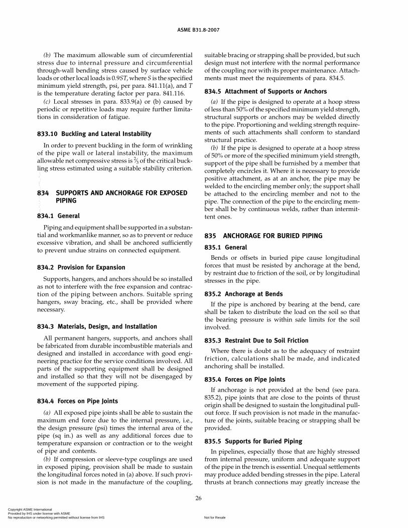
ASME B31.8-2007
(b) The maximum allowable sum of circumferentialstress due to internal pressure and circumferentialthrough-wall bending stress caused by surface vehicleloads or other local loads is 0.9ST, where S is the specifiedminimum yield strength, psi, per para. 841.11(a), and Tis the temperature derating factor per para. 841.116.
(c) Local stresses in para. 833.9(a) or (b) caused byperiodic or repetitive loads may require further limita-tions in consideration of fatigue.
833.10 Buckling and Lateral Instability
In order to prevent buckling in the form of wrinklingof the pipe wall or lateral instability, the maximumallowable net compressive stress is 2⁄3 of the critical buck-ling stress estimated using a suitable stability criterion.
834 SUPPORTS AND ANCHORAGE FOR EXPOSEDPIPING
834.1 General
Piping and equipment shall be supported in a substan-tial and workmanlike manner, so as to prevent or reduceexcessive vibration, and shall be anchored sufficientlyto prevent undue strains on connected equipment.
834.2 Provision for Expansion
Supports, hangers, and anchors should be so installedas not to interfere with the free expansion and contrac-tion of the piping between anchors. Suitable springhangers, sway bracing, etc., shall be provided wherenecessary.
834.3 Materials, Design, and Installation
All permanent hangers, supports, and anchors shallbe fabricated from durable incombustible materials anddesigned and installed in accordance with good engi-neering practice for the service conditions involved. Allparts of the supporting equipment shall be designedand installed so that they will not be disengaged bymovement of the supported piping.
834.4 Forces on Pipe Joints
(a) All exposed pipe joints shall be able to sustain themaximum end force due to the internal pressure, i.e.,the design pressure (psi) times the internal area of thepipe (sq in.) as well as any additional forces due totemperature expansion or contraction or to the weightof pipe and contents.
(b) If compression or sleeve-type couplings are usedin exposed piping, provision shall be made to sustainthe longitudinal forces noted in (a) above. If such provi-sion is not made in the manufacture of the coupling,
26
suitable bracing or strapping shall be provided, but suchdesign must not interfere with the normal performanceof the coupling nor with its proper maintenance. Attach-ments must meet the requirements of para. 834.5.
834.5 Attachment of Supports or Anchors
(a) If the pipe is designed to operate at a hoop stressof less than 50% of the specified minimum yield strength,structural supports or anchors may be welded directlyto the pipe. Proportioning and welding strength require-ments of such attachments shall conform to standardstructural practice.
(b) If the pipe is designed to operate at a hoop stressof 50% or more of the specified minimum yield strength,support of the pipe shall be furnished by a member thatcompletely encircles it. Where it is necessary to providepositive attachment, as at an anchor, the pipe may bewelded to the encircling member only; the support shallbe attached to the encircling member and not to thepipe. The connection of the pipe to the encircling mem-ber shall be by continuous welds, rather than intermit-tent ones.
835 ANCHORAGE FOR BURIED PIPING
835.1 General
Bends or offsets in buried pipe cause longitudinalforces that must be resisted by anchorage at the bend,by restraint due to friction of the soil, or by longitudinalstresses in the pipe.
835.2 Anchorage at Bends
If the pipe is anchored by bearing at the bend, careshall be taken to distribute the load on the soil so thatthe bearing pressure is within safe limits for the soilinvolved.
835.3 Restraint Due to Soil Friction
Where there is doubt as to the adequacy of restraintfriction, calculations shall be made, and indicatedanchoring shall be installed.
835.4 Forces on Pipe Joints
If anchorage is not provided at the bend (see para.835.2), pipe joints that are close to the points of thrustorigin shall be designed to sustain the longitudinal pull-out force. If such provision is not made in the manufac-ture of the joints, suitable bracing or strapping shall beprovided.
835.5 Supports for Buried Piping
In pipelines, especially those that are highly stressedfrom internal pressure, uniform and adequate supportof the pipe in the trench is essential. Unequal settlementsmay produce added bending stresses in the pipe. Lateralthrusts at branch connections may greatly increase the
Copyright ASME International Provided by IHS under license with ASME
Not for ResaleNo reproduction or networking permitted without license from IHS
--`,,```,,,,````-`-`,,`,,`,`,,`---

ASME B31.8-2007
stresses in the branch connection itself, unless the fill isthoroughly consolidated or other provisions are madeto resist the thrust.
Rock shield shall not be draped over the pipe unlesssuitable backfill and padding are placed in the ditch toprovide a continuous and adequate support of the pipein the trench.
835.51 When openings are made in a consolidatedbackfill to connect new branches to an existing line, caremust be taken to provide firm foundation for both theheader and the branch to prevent vertical and lateralmovements.
27
835.6 Interconnection of Underground Lines
Underground lines are subjected to longitudinalstresses due to changes in pressure and temperature.For long lines, the friction of the earth will preventchanges in length from these stresses, except for severalhundred feet adjacent to bends or ends. At these loca-tions, the movement, if unrestrained, may be of consider-able magnitude. If connections are made at such alocation to a relatively unyielding line or other fixedobject, it is essential that the interconnection shall haveample flexibility to compensate for possible movement,or the line shall be provided with an anchor sufficientto develop the forces necessary to limit the movement.
Copyright ASME International Provided by IHS under license with ASME
Not for ResaleNo reproduction or networking permitted without license from IHS
--`,,```,,,,````-`-`,,`,,`,`,,`---

ASME B31.8-2007
Chapter IVDesign, Installation, and Testing
840 DESIGN, INSTALLATION, AND TESTING
840.1 General Provisions
(a) The design requirements of this Code are intendedto be adequate for public safety under all conditionsencountered in the gas industry. Conditions that maycause additional stress in any part of a line or its appurte-nances shall be provided for, using good engineeringpractice. Examples of such conditions include long self-supported spans, unstable ground, mechanical or sonicvibration, weight of special attachments, earthquake-induced stresses, stresses caused by temperature differ-ences, and the soil and temperature conditions foundin the Arctic. Temperature differences shall be taken asthe difference between the lowest and highest expectedmetal temperature during pressure test and/oroperating services having due regard to past recordedtemperature data and the possible effects of lower orhigher air and ground temperature.
(b) The quality of the gas to be transported in thepipeline, or by the pipeline system, shall be consideredwhen designing facilities. Measures shall be taken tocontrol or minimize adverse effects of the gas propertiesor gas composition when any of the following may bea concern:
(1) Gas Composition. Uncontrolled or unexpectedvariations in heating value may result in problems atthe end user’s burner tip or process. Noncombustiblecompounds (e.g., nitrogen, nitrogen compounds, carbondioxide, etc.) may reduce the heating value and increasethe specific gravity of the gas stream. Carbon dioxidecontributes to internal corrosion in the presence of freewater. Increased specific gravity of the gas stream mayforetell the condensing of heavy hydrocarbons at coolertemperatures which may negatively affect operations.A change in specific gravity may affect pipeline andcompressor capacity calculations. For effects of heavyhydrocarbons on the design of pipe for Ductile FractureArrest, see the “caution” at the end of para. 841.11.
(2) Hydrogen Sulfide Content. Hydrogen sulfide ishighly toxic and contributes to corrosion in the presenceof water. Refer to Chapter IX, Sour Gas, for specificprovisions related to hydrogen sulfide.
(3) Oxygen Content. Oxygen contributes to corro-sion problems in the presence of free water at certaintemperatures. Certain mixtures of oxygen and gas abovethe lower explosive limit can create an explosive condi-tion. Refer to paras. 841.27, 850.6, and 863.
28
(4) Water Vapor Content and Free Liquids. Free waterand hydrocarbons at certain combinations of pressuresand temperatures may produce hydrates, which arecrystalline solids that may cause partial or completepipeline blockages, that may lead to a disruption ofpipeline operations.
Based on the characteristics of the gas stream (i.e.,heating value, specific gravity, temperature, free liquid,odorization, impurities, and other objectionable sub-stances), appropriate precautions shall be considered toaddress any problems that might adversely affect thepipeline system or the end user.
(c) The most significant factor contributing to the fail-ure of a gas pipeline is damage to the line caused bythe activities of people along the route of the line. Dam-age will generally occur during construction of otherfacilities associated with providing the services associ-ated with human dwellings and commercial or indus-trial enterprises. These services, such as water, gas andelectrical supply, sewage systems, drainage lines andditches, buried power and communication cables, streetsand roads, etc., become more prevalent and extensive,and the possibility of damage to the pipeline becomesgreater with larger concentrations of buildings intendedfor human occupancy. Determining the Location Classprovides a method of assessing the degree of exposureof the line to damage.
A pipeline designed, constructed, and operated inaccordance with the requirements of Location Class 1[see para. 840.22(a)] is basically safe for pressure contain-ment in any location; however, additional measures arenecessary to protect the integrity of the line in the pres-ence of activities that might cause damage. One of themeasures required by this Code is to lower the stresslevel in relation to increased public activity. This activityis quantified by determining Location Class and relatingthe design of the pipeline to the appropriate designfactor.
(d) Early editions of this Code used the term “popula-tion density index” to determine design, construction,testing, and operation requirements. They also used theterm “Location Class” in prescribing design pressure,type of construction, and maximum allowable operatingpressure. To simplify use of this Code, the term “popula-tion density index” was eliminated. Construction TypesA, B, C, and D were eliminated and replaced with thesame terminology used for design–location class.
Copyright ASME International Provided by IHS under license with ASME
Not for ResaleNo reproduction or networking permitted without license from IHS
--`,,```,,,,````-`-`,,`,,`,`,,`---

ASME B31.8-2007
The requirements based on Location Class were suchthat there were no significant changes in the design,installation, testing, and operation of piping systemsdue to changes in terminology.
Pipelines constructed prior to the publication of thisEdition and designed in accordance with location classesestablished in compliance with previous editions of thisCode may continue to use the location classes so deter-mined, provided that when observed increases in thenumber of buildings intended for human occupancyoccur, the Location Class determination shall be as pre-sented in para. 840.2.
840.2 Buildings Intended for Human Occupancy
840.21 General(a) To determine the number of buildings intended
for human occupancy for an onshore pipeline, lay outa zone 1⁄4 mile wide along the route of the pipeline withthe pipeline on the centerline of this zone, and dividethe pipeline into random sections 1 mile in length suchthat the individual lengths will include the maximumnumber of buildings intended for human occupancy.Count the number of buildings intended for humanoccupancy within each 1-mile zone. For this purpose,each separate dwelling unit in a multiple dwelling unitbuilding is to be counted as a separate building intendedfor human occupancy.
It is not intended here that a full mile of lower stresslevel pipeline shall be installed if there are physical barri-ers or other factors that will limit the further expansionof the more densely populated area to a total distanceof less than 1 mile. It is intended, however, that whereno such barriers exist, ample allowance shall be madein determining the limits of the lower stress design toprovide for probable further development in the area.
(b) When a cluster of buildings intended for humanoccupancy indicates that a basic mile of pipeline shouldbe identified as a Location Class 2 or Location Class 3,the Location Class 2 or Location Class 3 may be termi-nated 660 ft from the nearest building in the cluster.
(c) For pipelines shorter than 1 mile in length, aLocation Class that is typical of the Location Class thatwould be required for 1 mile of pipeline traversing thearea shall be assigned.
840.22 Location Classes for Design and Construction(a) Location Class 1. A Location Class 1 is any 1-mile
section that has 10 or fewer buildings intended forhuman occupancy. A Location Class 1 is intended toreflect areas such as wasteland, deserts, mountains, graz-ing land, farmland, and sparsely populated areas.
(1) Class 1, Division 1. This Division is a LocationClass 1 where the design factor of the pipe is greaterthan 0.72 but equal to or less than 0.80 and has beenhydrostatically tested to 1.25 times the maximumoperating pressure. (See Table 841.114B for exceptionsto design factor.)
29
(2) Class 1, Division 2. This Division is a LocationClass 1 where the design factor of the pipe is equal toor less than 0.72 and has been tested to 1.1 times themaximum operating pressure. (See Table 841.114B forexceptions to design factor.)
(b) Location Class 2. A Location Class 2 is any 1-milesection that has more than 10 but fewer than 46 buildingsintended for human occupancy. A Location Class 2 isintended to reflect areas where the degree of populationis intermediate between Location Class 1 and LocationClass 3, such as fringe areas around cities and towns,industrial areas, ranch or country estates, etc.
(c) Location Class 3. A Location Class 3 is any 1-milesection that has 46 or more buildings intended forhuman occupancy except when a Location Class 4 pre-vails. A Location Class 3 is intended to reflect areas suchas suburban housing developments, shopping centers,residential areas, industrial areas, and other populatedareas not meeting Location Class 4 requirements.
(d) Location Class 4. Location Class 4 includes areaswhere multistory buildings are prevalent, where trafficis heavy or dense, and where there may be numerousother utilities underground. Multistory means four ormore floors above ground including the first or groundfloor. The depth of basements or number of basementfloors is immaterial.
840.3 Considerations Necessary for Concentrationsof People in Location Class 1 or 2
(a) In addition to the criteria contained in para. 840.2,additional consideration must be given to the possibleconsequences of a failure near areas where a concentra-tion of people is likely, such as a church, school, multipledwelling unit, hospital, or recreational area of an orga-nized character in Location Class 1 or 2.
If the facility is used infrequently, the requirementsof subpara. (b) need not be applied.
(b) Pipelines near places of public assembly or con-centrations of people, such as churches, schools, multi-ple dwelling unit buildings, hospitals, or recreationalareas of an organized nature in Location Class 1 or 2shall meet requirements for Location Class 3.
(c) Concentrations of people referred to in subparas.(a) and (b) above are not intended to include groups offewer than 20 people per instance or location but areintended to cover people in an outside area as well asin a building.
840.4 Intent
840.41 It should be emphasized that LocationClass (1, 2, 3, or 4) as described in the previous para-graphs is defined as the general description of a geo-graphic area having certain characteristics as a basisfor prescribing the types of design, construction, andmethods of testing to be used in those locations or inareas that are comparable. A numbered Location Class,
Copyright ASME International Provided by IHS under license with ASME
Not for ResaleNo reproduction or networking permitted without license from IHS
--`,,```,,,,````-`-`,,`,,`,`,,`---

ASME B31.8-2007
such as Location Class 1, refers only to the geographyof that location or a similar area and does not necessarilyindicate that a design factor of 0.72 will suffice for allconstruction in that particular location or area (e.g., inLocation Class 1, all aerial crossings require a designfactor of 0.6; see para. 841.122).
840.42 When classifying locations for determiningthe design factor for pipeline construction and testingthat should be prescribed, due consideration shall begiven to the possibility of future development of thearea. If at the time of planning a new pipeline this futuredevelopment appears likely to be sufficient to changethe Class Location, this shall be taken into considerationin the design and testing of the proposed pipeline.
841 STEEL PIPE
841.1 Steel Piping Systems Design Requirements
841.11 Steel Pipe Design Formula(a) The design pressure for steel gas piping systems
or the nominal wall thickness for a given design pressureshall be determined by the following formula (for limita-tions, see para. 841.111):
P p2StD
FET
whereD p nominal outside diameter of pipe, in.E p longitudinal joint factor obtained from
Table 841.115A [see also para. 817.13(d)]F p design factor obtained from Table 841.114A. In
setting the values of the design factor, F, dueconsideration has been given and allowance hasbeen made for the various underthickness toler-ances provided for in the pipe specificationslisted and approved for usage in this Code.
P p design pressure, psig (see also para. 841.111)S p specified minimum yield strength, psi, stipu-
lated in the specifications under which the pipewas purchased from the manufacturer or deter-mined in accordance with paras. 817.13(h) and841.112. The specified minimum yield strengthsof some of the more commonly used pipingsteels whose specifications are incorporated byreference herein are tabulated for conveniencein Appendix D.
T p temperature derating factor obtained fromTable 841.116A
t p nominal wall thickness, in.
(b) The design factor for pipelines in Location Class1, Division 1 is based on gas pipeline operational experi-ence at operation levels in excess of those previouslyrecommended by this Code.
30
It should be noted that the user may be required tochange out such pipe or reduce pressure to 0.72 SMYSmaximum in accordance with para. 854.2.
(c) Fracture Control and Arrest. A fracture toughnesscriterion or other method shall be specified to controlfracture propagation when a pipeline is designed tooperate either at a hoop stress over 40% through 80%of SMYS in sizes NPS 16 or larger, or at a hoop stressover 72% through 80% of SMYS in sizes smaller thanNPS 16.
When a fracture toughness criterion is used, controlcan be achieved by ensuring that the pipe has adequateductility and either by specifying adequate toughnessor installing crack arrestors on the pipeline to stop prop-agation.
(1) Brittle Fracture Control. To ensure that the pipehas adequate ductility, fracture toughness testing shallbe performed in accordance with the testing proceduresof supplementary requirements SR5 or SR6 of API 5L,or other equivalent alternatives. If the operating temper-ature is below 50°F, an appropriate lower test tempera-ture shall be used. The appropriate lower testtemperature shall be taken to be at or below the lowestexpected metal temperature during pressure testing (ifwith air or gas) and during service, having regard topast recorded temperature data and possible effects oflower air and ground temperatures. The average shearvalue of the fracture appearance of three Charpy speci-mens from each heat shall not be less than 60%, and theall-heat average for each order per diameter, size, andgrade shall not be less than 80%. Alternatively, whendrop-weight tear testing is specified, at least 80% of theheats shall exhibit a fracture appearance shear area of40% or more at the specified test temperature.
(2) Ductile Fracture Arrest. To ensure that the pipe-line has adequate toughness to arrest a ductile fracture,the pipe shall be tested in accordance with the proce-dures of supplementary requirements SR5 of API 5L.The all-heat average of the Charpy energy values shallmeet or exceed the energy value calculated using oneof the following equations that have been developed invarious pipeline research programs.
(a) Battelle Columbus Laboratories (BCL) (AGA)
CVN p 0.0108�2R1/3t1/3
(b) American Iron and Steel Institute (AISI)
CVN p 0.0345�3/2R1/2
(c) British Gas Council (BGC)
CVN p 0.0315�R/t1/2
(d) British Steel Corporation (BSC)
CVN p 0.00119�2R
Copyright ASME International Provided by IHS under license with ASME
Not for ResaleNo reproduction or networking permitted without license from IHS
--`,,```,,,,````-`-`,,`,,`,`,,`---

ASME B31.8-2007
whereCVN p full-size Charpy V-notch absorbed energy,
ft-lbR p pipe radius, in.t p wall thickness, in.
� p hoop stress, ksi
(3) Mechanical Crack Arrestors. Mechanical crackarrestors consisting of sleeves, wire-rope wrap, heavy-wall pipe, or other suitable types have been shown toprovide reliable methods of arresting ductile fracture.The mechanical crack arrestors shall be placed at inter-vals along the pipeline.
CAUTION: The requirements specified in (c)(2) above assumethe pipeline is transporting essentially pure methane and thepipe is similar in fracture behavior to that used to develop theempirical equations above. The presence of heavier hydrocar-bons can cause the gas to exhibit two-phase behavior on suddendecompression and thus requires a greater Charpy energy toarrest propagating pipe fracture. Likewise, pipe that has beencontrol rolled or quench and tempered may not behave as indi-cated by the equations and may also require a greater Charpyenergy to arrest a propagating fracture. Calculations must beperformed to determine if the decompression exhibits two-phasebehavior, and an assessment must be made as to the applicabilityof the arrest equations where additional toughness may berequired. Otherwise, mechanical crack arrestors [see (c)(3) above]should be installed, or the Charpy toughness requirements forarrest should be verified through experiments or additional cal-culations.
841.111 Limitations on Design Pressure P in Para.841.11. The design pressure obtained by the formula inpara. 841.11 shall be reduced to conform to the following:
(a) P for furnace butt welded pipe shall not exceed therestrictions of para. 841.11 or 60% of mill test pressure,whichever is the lesser.
(b) P shall not exceed 85% of the mill test pressurefor all other pipes provided; however, that pipe, milltested to a pressure less than 85% of the pressurerequired to produce a hoop stress equal to the specifiedminimum yield, may be retested with a mill type hydro-static test or tested in place after installation. In theevent the pipe is retested to a pressure in excess of themill test pressure, then P shall not exceed 85% of theretest pressure rather than the initial mill test pressure.It is mandatory to use a liquid as the test medium inall tests in place after installation where the test pressureexceeds the mill test pressure. This paragraph is not tobe construed to allow an operating pressure or designpressure in excess of that provided for by para. 841.11.
841.112 Limitations on Specified Minimum YieldStrength S in Para. 841.11
(a) If the pipe under consideration is not new pipepurchased under a specification approved and listed inthis Code, the value of S may be determined in accor-dance with one of the following:
(1) S value for new pipe qualified under para.811.221 or 811.222
31
(2) S value for reuse of steel pipe qualified underone of the provisions of para. 817.1
(3) S value for pipe of unknown specification asdetermined by para. 817.13(h)
(b) When pipe that has been cold worked for meetingthe specified minimum yield strength is subsequentlyheated to a temperature higher than 900°F for any periodof time or over 600°F for more than 1 hr, the maximumallowable pressure at which it can be used shall notexceed 75% of the value obtained by use of the steelpipe design formula given in para. 841.11.
(c) In no case where the Code refers to the specifiedminimum value of a mechanical property shall thehigher actual value of a property be substituted in thesteel pipe design formula given in para. 841.11. If theactual value is less than the specified minimum valueof a mechanical property, the actual value may be usedwhere it is permitted by the Code, such as in para. 817.1regarding the reuse of steel pipe.
841.113 Additional Requirements for Nominal WallThickness t in Para. 841.11
(a) The minimum wall thickness t required for pres-sure containment as determined by para. 841.11 maynot be adequate for other forces to which the pipelinemay be subjected. [See para. 840.1(a).] Considerationshall also be given to loading due to transportation orhandling of the pipe during construction, weight ofwater during testing, and soil loading and other second-ary loads during operation. (See para. 841.145 for sug-gested methods to provide additional protection.)Consideration should also be given to welding ormechanical joining requirements. Standard wall thick-ness, as prescribed in ASME B36.10M, shall be the leastnominal wall thickness used for threaded andgrooved pipe.
(b) Transportation, installation, or repair of pipe shallnot reduce the wall thickness at any point to a thicknessless than 90% of the nominal wall thickness as deter-mined by para. 841.11 for the design pressure to whichthe pipe is to be subjected.
841.114 Design Factors F and Location Classes.The design factor in Table 841.114A shall be used forthe designated Location Class. All exceptions to basicdesign factors to be used in the design formula are givenin Table 841.114B.
841.115 The longitudinal joint factor shall be inaccordance with Table 841.115A.
841.116 The temperature derating factor shallbe in accordance with Table 841.116A.
841.12 Additional Design Information or Instructions
841.121 Fabricated Assemblies. When fabricatedassemblies, such as connections for separators, mainline valve assemblies, cross connections, river crossing
(07)
Copyright ASME International Provided by IHS under license with ASME
Not for ResaleNo reproduction or networking permitted without license from IHS
--`,,```,,,,````-`-`,,`,,`,`,,`---

ASME B31.8-2007
Table 841.114A Basic Design Factor, F
Design Factor,Location Class F
Location Class 1, Division 1 0.80Location Class 1, Division 2 0.72Location Class 2 0.60Location Class 3 0.50Location Class 4 0.40
Table 841.114B Design Factors for Steel Pipe Construction
Location Class
1
Facility Div. 1 Div. 2 2 3 4
Pipelines, mains, and service lines [see para. 840.21(b)] 0.80 0.72 0.60 0.50 0.40
Crossings of roads, railroads without casing:(a) Private roads 0.80 0.72 0.60 0.50 0.40(b) Unimproved public roads 0.60 0.60 0.60 0.50 0.40(c) Roads, highways, or public streets, with hard surface and railroads 0.60 0.60 0.50 0.50 0.40
Crossings of roads, railroads with casing:(a) Private roads 0.80 0.72 0.60 0.50 0.40(b) Unimproved public roads 0.72 0.72 0.60 0.50 0.40(c) Roads, highways, or public streets, with hard surface and railroads 0.72 0.72 0.60 0.50 0.40
Parallel encroachment of pipelines and mains on roads and railroads:(a) Private roads 0.80 0.72 0.60 0.50 0.40(b) Unimproved public roads 0.80 0.72 0.60 0.50 0.40(c) Roads, highways, or public streets, with hard surface and railroads 0.60 0.60 0.60 0.50 0.40
Fabricated assemblies (see para. 841.121) 0.60 0.60 0.60 0.50 0.40Pipelines on bridges (see para. 841.122) 0.60 0.60 0.60 0.50 0.40Pressure/flow control and metering facilities (see para. 841.123) 0.60 0.60 0.60 0.50 0.40
Compressor station piping 0.50 0.50 0.50 0.50 0.40
Near concentration of people in Location Classes 1 and 2 [see para. 840.3(b)] 0.50 0.50 0.50 0.50 0.40
headers, etc., are to be installed in areas defined in Loca-tion Class 1, a design factor of 0.6 is required throughoutthe assembly and for a distance equal to the lesser of5 diameters or 10 ft in each direction beyond the lastfitting. A shorter distance may be used provided thatcombined stresses are considered in the design of theinstallation. Transition pieces at the end of an assemblyand elbows used in place of pipe bends are not consid-ered fittings under the requirements of this paragraph.Also see para. 822.
841.122 Pipelines or Mains on Bridges. Thedesign factor for pipelines or mains supported by rail-road, vehicular, pedestrian, or pipeline bridges shall bedetermined in accordance with the Location Class pre-scribed for the area in which the bridge is located. InLocation Class 1, however, a design factor of 0.6 shallbe used.
32
841.123 Design of Metering and Pressure/FlowControl Facilities
(a) All piping and piping components, up to andincluding the outlet stop valve(s) of individual meterand pressure/flow control runs, shall meet or exceedthe maximum design pressure of the inlet piping system.Threaded reducing bushings should not be used in pres-sure/flow control facilities where they are subject to highfrequency piping vibrations. The design requirementsof para. 840.3 and Table 841.114B apply to the designrequirements of this section.
(b) All piping shall be tested in accordance withpara. 841.3 and the class location requirements ofTable 841.114B. Instrumentation devices such as trans-mitters, recorders, controllers, etc., excluding testinginstrumentation, should be isolated from the piping dur-ing the test. Test fluids shall be removed from piping
(07)
Copyright ASME International Provided by IHS under license with ASME
Not for ResaleNo reproduction or networking permitted without license from IHS
--`,,```,,,,````-`-`,,`,,`,`,,`---

ASME B31.8-2007
Table 841.115A Longitudinal Joint Factor, E
Spec. No. Pipe Class E Factor
ASTM A 53 Seamless 1.00Electric Resistance Welded 1.00Furnace Butt Welded: Continuous Weld 0.60
ASTM A 106 Seamless 1.00ASTM A 134 Electric Fusion Arc Welded 0.80ASTM A 135 Electric Resistance Welded 1.00ASTM A 139 Electric Fusion Welded 0.80ASTM A 211 Spiral Welded Steel Pipe 0.80ASTM A 333 Seamless 1.00
Electric Resistance Welded 1.00ASTM A 381 Double Submerged-Arc-Welded 1.00ASTM A 671 Electric Fusion Welded
Classes 13, 23, 33, 43, 53 0.80Classes 12, 22, 32, 42, 52 1.00
ASTM A 672 Electric Fusion WeldedClasses 13, 23, 33, 43, 53 0.80Classes 12, 22, 32, 42, 52 1.00
API 5L Seamless 1.00Electric Resistance Welded 1.00Electric Flash Welded 1.00Submerged Arc Welded 1.00Furnace Butt Welded 0.60
GENERAL NOTE: Definitions for the various classes of welded pipeare given in para. 804.243.
Table 841.116A Temperature Derating Factor,T, for Steel Pipe
Temperature DeratingTemperature, °F Factor, T
250 or less 1.000300 0.967350 0.933400 0.900450 0.867
GENERAL NOTE: For intermediate temperatures, interpolate for derat-ing factor.
and piping components and the piping purged withnatural gas before placing the facilities in service.
(c) The corrosion control measures in Chapter VI, asappropriate, must be applied to meter andpressure/flow control piping.
841.124 Metering Facilities. Particular consider-ation and attention shall be given to sizing meter runblowdowns and/or flow restricting plates for turbineand positive displacement meters. Rapid depressuriza-tion of meter runs can damage or destroy meters due tometer overspin and high differentials and can endangerpersonnel.
33
841.125 Other (Nonmandatory) Considerations forMetering Facilities
(a) Meter proving reduces measurement uncertainty.Where meter design, size, and flow rate allows, considerinstalling meter proving taps.
(b) Upstream dry gas filter(s) should be consideredwhen installing rotary or turbine meters. Particulatesand pipeline dust can contaminate meter lubricating oiland damage bearings and other internal meter compo-nents.
841.126 Pressure/Flow Control Facilities(a) Overpressure protection shall be provided by the
use of(1) a monitor regulator in series with a controlling
regulator (each regulator run)(2) adequately sized relief valve(s) downstream of
the controlling regulator(s)(3) overpressure shutoff valve(s) upstream or down-
stream of the controlling regulator(s). Installation ofalarm devices which indicate primary (controlling) regu-lator failure are useful and should be considered formonitor regulator systems.
(b) Each regulator supply, control, and sensing lineshall have a separate isolation valve for isolation pur-poses during regulator set-up and maintenance and toprevent a safety device (i.e., monitor, regulator) frombecoming unintentionally inoperable due to pluggingor freezing of instrument lines.
(c) Steps shall be taken to prevent the freezing-up(internal and external) of regulators, control valves,instrumentation, pilot controls, and valve actuationequipment caused by moisture saturated instrument airor gas, pipeline gas, or external ambient conditions.
(d) Sound pressure levels of 110 dbA and greater shallbe avoided to prevent damage to control equipment andpiping.
(e) Gas velocities in piping should not exceed100 ft/sec at peak conditions. Lower velocities are rec-ommended. High gas velocities in piping increase turbu-lence and pressure drop and contribute to excessivesound pressure levels (aerodynamic noise) and cancause internal piping erosion.
841.127 Other (Nonmandatory) Considerations forPressure/Flow Control Facilities
(a) Filtration of gas, particularly for instrumentation,instrument regulators, etc., should be considered whereparticulate contaminants are a present or potentialproblem.
(b) Installation of conical reducers immediatelydownstream of a regulator or control valve will allowa more gradual expansion of gas to larger piping andreduce turbulence and pressure drop during gasexpansion.
Copyright ASME International Provided by IHS under license with ASME
Not for ResaleNo reproduction or networking permitted without license from IHS
--`,,```,,,,````-`-`,,`,,`,`,,`---
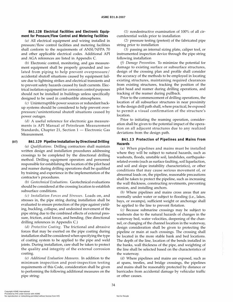
(07)
ASME B31.8-2007
841.128 Electrical Facilities and Electronic Equip-ment for Pressure/Flow Control and Metering Facilities
(a) All electrical equipment and wiring installed inpressure/flow control facilities and metering facilitiesshall conform to the requirements of ANSI/NFPA 70and other applicable electrical codes. Additional APIand AGA references are listed in Appendix C.
(b) Electronic control, monitoring, and gas measure-ment equipment shall be properly grounded and iso-lated from piping to help prevent overpressure/accidental shutoff situations caused by equipment fail-ure due to lightning strikes and electrical transients andto prevent safety hazards caused by fault currents. Elec-trical isolation equipment for corrosion control purposesshould not be installed in buildings unless specificallydesigned to be used in combustible atmospheres.
(c) Uninterruptible power sources or redundant back-up systems should be considered to help prevent over-pressure/unintentional shutoff situations caused bypower outages.
(d) A useful reference for electronic gas measure-ments is API Manual of Petroleum MeasurementStandards, Chapter 21, Section 1 — Electronic GasMeasurement.
841.129 Pipeline Installation by Directional Drilling(a) Qualifications. Drilling contractors shall maintain
written design and installation procedures addressingcrossings to be completed by the directional drillingmethod. Drilling equipment operators and personnelresponsible for establishing the location of the pilot headand reamer during drilling operations shall be qualifiedby training and experience in the implementation of thecontractor’s procedures.
(b) Geotechnical Evaluations. Geotechnical evaluationsshould be considered at the crossing location to establishsubsurface conditions.
(c) Installation Forces and Stresses. Loads on, andstresses in, the pipe string during installation shall beevaluated to ensure protection of the pipe against yield-ing, buckling, collapse, and undesired movement of thepipe string due to the combined effects of external pres-sure, friction, axial forces, and bending. (See directionaldrilling references in Appendix C.)
(d) Protective Coating. The frictional and abrasiveforces that may be exerted on the pipe coating duringinstallation shall be considered when specifying the typeof coating system to be applied to the pipe and weldjoints. During installation, care shall be taken to protectthe quality and integrity of the external corrosioncoating.
(e) Additional Evaluation Measures. In addition to theminimum inspection and post-inspection testingrequirements of this Code, consideration shall be givento performing the following additional measures on thepipe string:
34
(1) nondestructive examination of 100% of all cir-cumferential welds prior to installation
(2) pressure testing (pretest) of the fabricated pipestring prior to installation
(3) passing an internal sizing plate, caliper tool, orinstrumented inspection device through the pipe stringfollowing installation
(f) Damage Prevention. To minimize the potential fordamage to existing surface or subsurface structures,design of the crossing plan and profile shall considerthe accuracy of the methods to be employed in locatingexisting structures, maintaining required clearancesfrom existing structures, tracking the position of thepilot head and reamer during drilling operations, andtracking of the reamer during pullback.
Prior to the commencement of drilling operations, thelocation of all subsurface structures in near proximityto the design drill path shall, where practical, be exposedto permit a visual confirmation of the structure’slocation.
Prior to initiating the reaming operation, consider-ation shall be given to the potential impact of the opera-tion on all adjacent structures due to any realizeddeviations from the design path.
841.13 Protection of Pipelines and Mains FromHazards
(a) When pipelines and mains must be installedwhere they will be subject to natural hazards, such aswashouts, floods, unstable soil, landslides, earthquake-related events (such as surface faulting, soil liquefaction,and soil and slope instability characteristics), or otherconditions that may cause serious movement of, orabnormal loads on, the pipeline, reasonable precautionsshall be taken to protect the pipeline, such as increasingthe wall thickness, constructing revetments, preventingerosion, and installing anchors.
(b) Where pipelines and mains cross areas that arenormally under water or subject to flooding (i.e., lakes,bays, or swamps), sufficient weight or anchorage shallbe applied to the line to prevent flotation.
(c) Because submarine crossings may be subject towashouts due to the natural hazards of changes in thewaterway bed, water velocities, deepening of the chan-nel, or changing of the channel location in the waterway,design consideration shall be given to protecting thepipeline or main at such crossings. The crossing shallbe located in the more stable bank and bed locations.The depth of the line, location of the bends installed inthe banks, wall thickness of the pipe, and weighting ofthe line shall be selected based on the characteristics ofthe waterway.
(d) Where pipelines and mains are exposed, such asat spans, trestles, and bridge crossings, the pipelinesand mains shall be reasonably protected by distance orbarricades from accidental damage by vehicular trafficor other causes.
Copyright ASME International Provided by IHS under license with ASME
Not for ResaleNo reproduction or networking permitted without license from IHS
--`,,```,,,,````-`-`,,`,,`,`,,`---

(07)
ASME B31.8-2007
841.14 Cover, Clearance, and Casing Requirementsfor Buried Steel Pipelines and Mains
841.141 Cover Requirements for Mains. Buriedmains shall be installed with a cover not less than 24 in.Where this cover provision cannot be met, or whereexternal loads may be excessive, the main shall beencased, bridged, or designed to withstand any suchanticipated external loads. Where farming or other oper-ations might result in deep plowing, in areas subject toerosion, or in locations where future grading is likely,such as road, highway, railroad, and ditch crossings,additional protection shall be provided (See para.841.145 for suggested methods to provide additionalprotection.).
841.142 Cover Requirements for Pipelines. Exceptfor offshore pipelines, buried pipelines shall be installedwith a cover not less than that shown in the followingtable:
Cover, in.
For RockExcavation [Note (1)]
Pipe Size Pipe SizeFor Normal NPS 20 and Larger Than
Location Excavation Smaller NPS 20
Class 1 24 12 18Class 2 30 18 18Classes 3 and 4 30 24 24Drainage ditch at 36 24 24
public roads andrailroad cross-ings (all loca-tions)
NOTE:(1) Rock excavation is excavation that requires blasting.
Where these cover provisions cannot be met or whereexternal loads may be excessive, the pipeline shall beencased, bridged, or designed to withstand any suchanticipated external loads. In areas where farming orother operations might result in deep plowing, in areassubject to erosion, or in locations where future gradingis likely, such as at roads, highways, railroad crossings,and ditch crossings, additional protection shall be pro-vided. (See para. 841.145 for suggested methods to pro-vide additional protection.)
841.143 Clearance Between Pipelines or Mains andOther Underground Structures
(a) There shall be at least 6 in. of clearance whereverpossible between any buried pipeline and any otherunderground structure not used in conjunction with thepipeline. When such clearance cannot be attained, pre-cautions to protect the pipe shall be taken, such as theinstallation of casing, bridging, or insulating material.
(b) There shall be at least 2 in. of clearance whereverpossible between any buried gas main and any other
35
underground structure not used in conjunction with themain. When such clearance cannot be attained, precau-tions to protect the main shall be taken, such as theinstallation of insulating material or casing.
841.144 Casing Requirements Under Railroads,Highways, Roads, or Streets. Casings shall be designedto withstand the superimposed loads. Where there is apossibility of water entering the casing, the ends of thecasing shall be sealed. If the end sealing is of a type thatwill retain the maximum allowable operating pressureof the carrier pipe, the casing shall be designed for thispressure and at least to the design factor of 0.72. Ventingof sealed casings is not mandatory; however, if ventsare installed they should be protected from the weatherto prevent water from entering the casing. (Require-ments for crossings within casing of railroads and high-ways are shown in Table 841.114B.)
841.145 Additional Underground Pipe Protection.The pipe design factor, F, shall be in accordance withTable 841.114B for the crossing of roads and railroads.The guidance provided by API RP 1102, Steel PipelinesCrossing Railroads and Highways; or GRI Report No.91/0284, Guidelines for Pipelines Crossing Highways;or Gas Piping Technology Committee’s Guide MaterialAppendix G-15, Design of Uncased Pipelines Crossingof Highways and Railroads, may be considered fordesign and installation of pipeline crossing. The pipelineoperator shall evaluate the need for extending additionalpipe protection over the pipeline when the road or rail-road right-of-way width is undefined based on antici-pated loading from traffic or heavy equipmentperforming maintenance activities adjacent to the roador railroad.
Varying degrees of additional protection from third-party damage to a buried main or pipeline crossingwithin (or parallel to) the right-of-way of road or railroadmay be achieved using the following techniques, or vari-ants thereof, singly or in combination.
(a) A physical barrier or marker may be installedabove or around the pipe (see para. 851.7). If a physicalbarrier is used, the potential conflict with the right-of-way maintenance activities should be recognized. Physi-cal barrier or marker methods include:
(1) a concrete or steel barrier placed above the pipe(2) a concrete slab placed vertically adjacent to the
pipe on each side and extended above the top of pipeelevation
(3) damage-resistant coating material, such asconcrete
(4) extra depth of cover additional to that requiredin para. 841.142
(5) buried high-visibility warning tape placed par-allel to and above the pipe
(6) pipe casing (see paras. 841.144, 862.117, and862.218)
Copyright ASME International Provided by IHS under license with ASME
Not for ResaleNo reproduction or networking permitted without license from IHS
--`,,```,,,,````-`-`,,`,,`,`,,`---

ASME B31.8-2007
(b) A heavier wall thickness than is required by thepipe design factor, F, in accordance with Table 841.114Aor Table 841.114B.
(c) Pipeline alignment should be as straight and per-pendicular to the road or railroad alignment as possibleto promote reliable marking of the pipe location throughthe right-of-way and at the right-of-way limits.
Additional underground pipe protection shall be usedin conjunction with an effective educational program(para. 850.44), periodic surveillance of pipelines(para. 851.1), pipeline patrolling (para. 851.2), and utili-zation of programs that provide notification to operatorsregarding impending excavation activity, if available.
841.15 Design factors are summarized inTable 841.114B.
841.2 Installation of Steel Pipelines and Mains
841.21 Construction Specifications. All construc-tion work performed on piping systems in accordancewith the requirements of this Code shall be done underconstruction specifications. The construction specifica-tions shall cover all phases of the work and shall be insufficient detail to cover the requirements of this Code.
841.22 Inspection Provisions
841.221 The operating company shall providesuitable inspection. Inspectors shall be qualified eitherby experience or training. The inspector shall have theauthority to order the repair or removal and replacementof any component found that fails to meet the standardsof this Code.
841.222 The installation inspection provisionsfor pipelines and other facilities to operate at hoopstresses of 20% or more of the specified minimum yieldstrength shall be adequate to make possible at least thefollowing inspections at sufficiently frequent intervalsto ensure good quality of workmanship.
(a) Inspect the surface of the pipe for serious surfacedefects just prior to the coating operation. [Seepara. 841.242(a).]
(b) Inspect the surface of the pipe coating as it islowered into the ditch to find coating lacerations thatindicate the pipe might have been damaged after beingcoated.
(c) Inspect the fitup of the joints before the weld ismade.
(d) Visually inspect the stringer beads before subse-quent beads are applied.
(e) Inspect the completed welds before they are cov-ered with coating.
(f ) Inspect the condition of the ditch bottom justbefore the pipe is lowered in, except for offshore pipe-lines.
(g) Inspect the fit of the pipe to the ditch before back-filling, except for offshore pipelines.
36
(h) Inspect all repairs, replacements, or changesordered before they are covered.
(i) Perform such special tests and inspections as arerequired by the specifications, such as nondestructivetesting of welds and electrical testing of the protectivecoating.
(j) Inspect backfill material prior to use and observebackfill procedure to ensure no damage occurs to thecoating in the process of backfilling.
841.23 Bends, Elbows, and Miters in Steel Pipelinesand Mains. Changes in direction may be made by theuse of bends, elbows, or miters under the limitationsnoted below.
841.231(a) A bend shall be free from buckling, cracks, or other
evidence of mechanical damage.(b) The maximum degree of bending on a field cold
bend may be determined by either method in the tablebelow. The first column expresses the maximum deflec-tion in an arc length equal to the nominal outside diame-ter, and the second column expresses the minimumradius as a function of the nominal outside diameter.
Deflection of Minimum Radius ofNominal Longitudinal Axis, Bend in Pipe DiametersPipe Size deg [see 841.231(c)]
Smaller than 12 841.231(d) 18D12 3.2 18D14 2.7 21D16 2.4 24D18 2.1 27D
20 and larger 1.9 30D
(c) A field cold bend may be made to a shorter mini-mum radius than permitted in (b) above, provided thecompleted bend meets all other requirements of thissection, and the wall thickness after bending is not lessthan the minimum permitted by para. 841.11. This maybe demonstrated through appropriate testing.
(d) For pipe smaller than NPS 12, the requirementsof (a) above must be met, and the wall thickness afterbending shall not be less than the minimum permittedby para. 841.11. This may be demonstrated throughappropriate testing.
(e) Except for offshore pipelines, when a circumferen-tial weld occurs in a bend section, it shall be subjectedto radiography examination after bending.
(f) All hot bends shall be made in accordance withASME B16.49.
(g) Wrinkle bends shall be permitted only on systemsoperating at hoop stress levels of less than 30% of thespecified minimum yield strength. When wrinkle bendsare made in welded pipe, the longitudinal weld shallbe located on or near to the neutral axis of the bend.Wrinkle bends with sharp kinks shall not be permitted.Spacing of wrinkles shall be measured along the crotchof the pipe bend, and the peak-to-peak distance between
(07)
Copyright ASME International Provided by IHS under license with ASME
Not for ResaleNo reproduction or networking permitted without license from IHS
--`,,```,,,,````-`-`,,`,,`,`,,`---

ASME B31.8-2007
the wrinkles shall exceed the diameter of the pipe. Onpipe NPS 16 and larger, the wrinkle shall not producean angle of more than 11⁄2 deg per wrinkle.
841.232 Mitered bends are permitted providedthe following limitations are met:
(a) In systems intended to operate at hoop stress lev-els of 40% or more of the specified minimum yieldstrength, mitered bends are not permitted. Deflectionscaused by misalignment up to 3 deg are not consideredas miters.
(b) In systems intended to operate at hoop stress lev-els of 10% or more but less than hoop stress levels of40% of the specified minimum yield strength, the totaldeflection angle at each miter shall not exceed 121⁄2 deg.
(c) In systems intended to operate at hoop stress lev-els of less than 10% of the specified minimum yieldstrength, the total deflection angle at each miter shallnot exceed 90 deg.
(d) In systems intended to operate at hoop stress lev-els of 10% or more of the specified minimum yieldstrength, the minimum distance between miters mea-sured at the crotch shall not be less than one pipediameter.
(e) Care shall be taken in making mitered joints toprovide proper spacing and alignment and full pene-tration.
841.233 Factory-made, wrought-steel weldingelbows or transverse segments cut therefrom may beused for changes in direction, provided that the arclength measured along the crotch is at least 1 in. on pipesizes NPS 2 and larger.
841.24 Pipe Surface Requirements Applicable toPipelines and Mains to Operate at a Hoop Stress of 20%or More of the Specified Minimum Yield Strength.Gouges, grooves, and notches have been found to be animportant cause of pipeline failures, and all harmfuldefects of this nature must be prevented, eliminated, orrepaired. Precautions shall be taken during manufacture,hauling, and installation to prevent the gouging orgrooving of pipe.
841.241 Detection of Gouges and Grooves(a) The field inspection provided on each job shall be
suitable to reduce to an acceptable minimum the chancesthat gouged or grooved pipe will get into the finishedpipeline or main. Inspection for this purpose just aheadof the coating operation and during the lowering-in andbackfill operation is required.
(b) When pipe is coated, inspection shall be madeto determine that the coating machine does not causeharmful gouges or grooves.
(c) Lacerations of the protective coating shall be care-fully examined prior to the repair of the coating to deter-mine if the pipe surface has been damaged.
37
841.242 Field Repair of Gouges and Grooves(a) Injurious gouges or grooves shall be removed.(b) Gouges or grooves may be removed by grinding
to a smooth contour, provided that the resulting wallthickness is not less than the minimum prescribed by thisCode for the conditions of usage. [See para. 841.113(b).]
(c) When the conditions outlined in para. 841.242(b)cannot be met, the damaged portion of pipe shall be cutout as a cylinder and replaced with a good piece. Insertpatching is prohibited.
841.243 Dents(a) A dent may be defined as a depression that pro-
duces a gross disturbance in the curvature of the pipewall (as opposed to a scratch or gouge, which reducesthe pipe wall thickness). The depth of a dent shall bemeasured as the gap between the lowest point of thedent and a prolongation of the original contour of thepipe in any direction.
(b) A dent, as defined in para. 841.243(a), which con-tains a stress concentrator such as a scratch, gouge,groove, or arc burn shall be removed by cutting out thedamaged portion of the pipe as a cylinder.
(c) All dents that affect the curvature of the pipe atthe longitudinal weld or any circumferential weld shallbe removed. All dents that exceed a maximum depth of1⁄4 in. in pipe NPS 12 and smaller or 2% of the nominalpipe diameter in all pipe greater than NPS 12 shall notbe permitted in pipelines or mains intended to operateat hoop stress levels of 40% or more of the specifiedminimum yield strength. When dents are removed, thedamaged portion of the pipe shall be cut out as a cylin-der. Insert patching and pounding out of the dents isprohibited.
841.244 Notches(a) Notches on the pipe surface can be caused by
mechanical damage in manufacture, transportation,handling, or installation, and when determined to bemechanically caused, shall be treated the same as gougesand grooves in para. 841.241.
(b) Stress concentrations that may or may not involvea geometrical notch may also be created by a processinvolving thermal energy in which the pipe surface isheated sufficiently to change its mechanical or metallur-gical properties. These imperfections are termed “metal-lurgical notches.” Examples include an arc burnproduced by accidental contact with a welding electrodeor a grinding burn produced by excessive force on agrinding wheel. Metallurgical notches may result in evenmore severe stress concentrations than a mechanicalnotch and shall be prevented or eliminated in all pipe-lines intended to operate at hoop stress levels of 20%or more of the specified minimum yield strength.
841.245 Elimination of Arc Burns. The metallurgi-cal notch caused by arc burns shall be removed by grind-ing, provided the grinding does not reduce the
Copyright ASME International Provided by IHS under license with ASME
Not for ResaleNo reproduction or networking permitted without license from IHS
--`,,```,,,,````-`-`,,`,,`,`,,`---

ASME B31.8-2007
remaining wall thickness to less than the minimum pre-scribed by this Code for the conditions of use.1 In allother cases, repair is prohibited, and the portion of pipecontaining the arc burn must be cut out as a cylinder andreplaced with a good piece. Insert patching is prohibited.Care shall be exercised to ensure that the heat of grindingdoes not produce a metallurgical notch.
841.25 Miscellaneous Operations Involved in theInstallation of Steel Pipelines and Mains
841.251 Handling, Hauling, and Stringing. Careshall be taken in the selection of the handling equipmentand in handling, hauling, unloading, and placing thepipe so as not to damage the pipe.
841.252 Installation of Pipe in the Ditch. Onpipelines operating at hoop stress levels of 20% or moreof the specified minimum yield strength, it is importantthat stresses imposed on the pipeline by constructionbe minimized. Except for offshore pipelines, the pipeshall fit the ditch without the use of external force tohold it in place until the backfill is completed. Whenlong sections of pipe that have been welded alongsidethe ditch are lowered in, care shall be exercised so asnot to jerk the pipe or impose any strains that may kinkor put a permanent bend in the pipe. Slack loops are notprohibited by this paragraph where laying conditionsrender their use advisable.
841.253 Backfilling(a) Backfilling shall be performed in a manner to pro-
vide firm support under the pipe.(b) If there are large rocks in the material to be used
for backfill, care shall be used to prevent damage to thecoating by such means as the use of rock shield material,or by making the initial fill with rock-free material suffi-cient to prevent damage.
(c) Where the trench is flooded to consolidate thebackfill, care shall be exercised to see that the pipe isnot floated from its firm bearing on the trench bottom.
841.26 Hot Taps. All hot taps shall be installed bytrained and experienced crews.
841.27 Precautions to Avoid Explosions of Gas–AirMixtures or Uncontrolled Fires During ConstructionOperations
841.271 Operations such as gas or electric weld-ing and cutting with cutting torches can be safely per-formed on pipelines, mains, and auxiliary equipment,provided that they are completely full of gas or of airthat is free from combustible material. Steps shall be
1 Complete removal of the metallurgical notch created by an arcburn can be determined as follows: After visible evidence of thearc burn has been removed by grinding, swab the ground areawith a 20% solution of ammonium persulfate. A blackened spotis evidence of a metallurgical notch and indicates that additionalgrinding is necessary.
38
taken to prevent a mixture of gas and air at all pointswhere such operations are to be performed.
841.272 When a pipeline or main can be keptfull of gas during a welding or cutting operation, thefollowing procedures are recommended:
(a) Keep a slight flow of gas moving toward the pointwhere cutting or welding is being done.
(b) Control the gas pressure at the site of the workby a suitable means.
(c) After a cut is made, immediately close all slotsor open ends with tape, tightly fitted canvas, or othersuitable materials.
(d) Do not permit two openings to remain uncoveredat the same time. This is doubly important if the twoopenings are at different elevations.
841.273 Welding, cutting, or other operationsthat could be a source of ignition shall not be done ona pipeline, main, or auxiliary apparatus that containsair, if it is connected to a source of gas, unless a suitablemeans has been provided to prevent the formation ofan explosive mixture in the work area.
841.274 In situations where welding or cuttingmust be done on facilities that are filled with air andconnected to a source of gas, and the precautions recom-mended above cannot be taken, one or more of the fol-lowing precautions, depending on circumstances at thejobsite, are suggested:
(a) purging of the pipe or equipment upon whichwelding or cutting is to be done with an inert gas orcontinuous purging with air in such a manner that acombustible mixture does not form in the facility at thework area
(b) testing of the atmosphere in the vicinity of thezone to be heated before the work is started and atintervals as the work progresses with a combustible gasindicator or by other suitable means
(c) careful verification before and during the workensuring that the valves that isolate the work from asource of gas do not leak
841.275 Purging of Pipelines and Mains(a) When a pipeline or main is to be placed in service,
the air in it shall be displaced. The following are someacceptable methods:
(1) Introduce a moderately rapid and continuousflow of gas into one end of the line and vent the air outthe other end. The gas flow shall be continued withoutinterruption until the vented gas is free of air.
(2) If the vent is in a location where the release ofgas into the atmosphere may cause a hazardous condi-tion, then a slug of inert gas shall be introduced betweenthe gas and air. The gas flow shall then be continuedwithout interruption until all of the air and inert gashave been removed from the facility. The vented gasesshall be monitored and the vent shall be closed before
Copyright ASME International Provided by IHS under license with ASME
Not for ResaleNo reproduction or networking permitted without license from IHS
--`,,```,,,,````-`-`,,`,,`,`,,`---

ASME B31.8-2007
any substantial quantity of combustible gas is releasedto the atmosphere.
(b) In cases where gas in a pipeline or main is to bedisplaced with air and the rate at which air can besupplied to the line is too small to make a proceduresimilar to but the reverse of that described in (a) abovefeasible, a slug of inert gas should be introduced toprevent the formation of an explosive mixture at theinterface between gas and air. Nitrogen or carbon diox-ide can be used for this purpose.
(c) If a pipeline or main containing gas is to beremoved, the operation may be carried out in accordancewith para. 841.272, or the line may be first disconnectedfrom all sources of gas and then thoroughly purged withair, water, or inert gas before any further cutting orwelding is done.
(d) If a gas pipeline, main, or auxiliary equipment isto be filled with air after having been in service andthere is a reasonable possibility that the inside surfacesof the facility are wetted with volatile inflammable liq-uid, or if such liquids might have accumulated in lowplaces, purging procedures designed to meet this situa-tion shall be used. Steaming of the facility until all com-bustible liquids have been evaporated and swept out isrecommended. Filling of the facility with an inert gasand keeping it full of such gas during the progress ofany work that might ignite an explosive mixture in thefacility is an alternative recommendation. The possibil-ity of striking static sparks within the facility must notbe overlooked as a possible source of ignition.
841.276 Whenever the accidental ignition in theopen air of gas-air mixture might be likely to causepersonal injury or property damage, precautions shallbe taken. For example:
(a) Prohibit smoking and open flames in the area.(b) Install a metallic bond around the location of cuts
in gas pipes to be made by means other than cuttingtorches.
(c) Take precautions to prevent static electricitysparks.
(d) Provide a fire extinguisher of appropriate size andtype, in accordance with ANSI/NFPA 10.
841.3 Testing After Construction
841.31 General Provisions. All piping systems shallbe tested after construction to the requirements of thisCode except for pretested fabricated assemblies, pre-tested tie-in sections, and tie-in connections.
The circumferential welds of welded tie-in connec-tions not pressure tested after construction shall beinspected by radiographic or other accepted nondestruc-tive methods in accordance with para. 826.2.
Nonwelded tie-in connections not pressure testedafter construction shall be leak tested at not less thanthe pressure available when the tie-in is placed intoservice.
39
841.32 Test Required to Prove Strength of Pipelinesand Mains to Operate at Hoop Stresses of 30% or Moreof the Specified Minimum Yield Strength of the Pipe
841.321 All pipelines and mains to be operatedat a hoop stress of 30% or more of the specified minimumyield strength of the pipe shall be given a test for atleast 2 hr to prove strength after construction and beforebeing placed in operation.
841.322 Location Classes 1 Through 4(a) Pipelines located in Location Class 1, Division 1
shall be tested hydrostatically to 1.25 times design pres-sure if the maximum operating pressure produces ahoop stress level greater than 72% SMYS. (Seepara. 841.36.)
(b) Pipelines located in Location Class 1, Division 2shall be tested either with air or gas to 1.1 times themaximum operating pressure or hydrostatically to atleast 1.1 times the maximum operating pressure if themaximum operating pressure produces a hoop stresslevel of 72% SMYS or less. (See para. 841.36.)
(c) Pipelines and mains in Location Class 2 shall betested either with air to 1.25 times the maximumoperating pressure or hydrostatically to at least1.25 times the maximum operating pressure. (Seepara. 841.36.)
(d) Pipelines and mains in Location Classes 3 and 4shall be tested hydrostatically to a pressure not lessthan 1.4 times the maximum operating pressure. Thisrequirement does not apply if, at the time the pipelineor main is first ready for test, one or both of the followingconditions exist:
(1) the ground temperature at pipe depth is 32°For less, or might fall to that temperature before thehydrostatic test could be completed, or
(2) water of satisfactory quality is not available insufficient quantity.
In such cases an air test to 1.1 times the maximumoperating pressure shall be made, and the limitationson operating pressure imposed by Table 841.322(f) donot apply.
(e) The test requirement given in paras. 841.322(a),(b), (c), and (d) are summarized in Table 841.322(f). (Seealso para. 816.)
(f) In selecting the test level, the designer or operatingcompany should be aware of the provisions of para. 854and the relationship between test pressure and operatingpressure when the pipeline experiences a future increasein the number of dwellings intended for human occu-pancy.
841.323 Other provisions of this Code notwith-standing, pipelines and mains crossing highways andrailroads may be tested in each case in the same mannerand to the same pressure as the pipeline on each sideof the crossing.
Copyright ASME International Provided by IHS under license with ASME
Not for ResaleNo reproduction or networking permitted without license from IHS
--`,,```,,,,````-`-`,,`,,`,`,,`---

ASME B31.8-2007
Table 841.322(f) Test Requirements for Pipelines and Mains to Operate at Hoop Stresses of30% or More of the Specified Minimum Yield Strength of the Pipe
1 2 3 4 5
Maximum AllowablePressure Test PrescribedLocation Permissible Operating Pressure,
Class Test Fluid Min. Max. the Lesser of
1 Water 1.25 � m.o.p. None t.p. � 1.25or d.p.
Division 1
1 Water 1.1 � m.o.p. None t.p. � 1.1Division 2 Air 1.1 � m.o.p. 1.1 � d.p. or d.p.
Gas 1.1 � m.o.p. 1.1 � d.p.
2 Water 1.25 � m.o.p. None t.p. � 1.25Air 1.25 � m.o.p. 1.25 � d.p. or d.p.
3 and 4 Water 1.40 � m.o.p. None t.p. � 1.40[Note (1)] or d.p.
d.p. p design pressurem.o.p. p maximum operating pressure (not necessarily the maximum allowable operating pressure)
t.p. p test pressure
GENERAL NOTE: This Table defines the relationship between test pressures and maximum allowable operating pressures subsequent to thetest. If an operating company decides that the maximum operating pressure will be less than the design pressure, a corresponding reductionin prescribed test pressure may be made as indicated in the Pressure Test Prescribed, Minimum, column. If this reduced test pressure isused, however, the maximum operating pressure cannot later be raised to the design pressure without retesting the line to the test pressureprescribed in the Pressure Test Prescribed, Maximum, column. See paras. 805.214, 845.213, and 845.214.
NOTE:(1) For exceptions, see para. 841.322(d).
841.324 Other provisions of this Code notwith-standing, fabricated assemblies, including main linevalve assemblies, cross connections, river crossing head-ers, etc., installed in pipelines in Location Class 1 anddesigned in accordance with a design factor of 0.60 asrequired in para. 841.121, may be tested as required forLocation Class 1.
841.325 Notwithstanding the limitations on airtesting imposed on para. 841.322(d), air testing may beused in Location Classes 3 and 4, provided that all ofthe following conditions apply:
(a) The maximum hoop stress during the test is lessthan 50% of the specified minimum yield strength inLocation Class 3, and less than 40% of the specifiedminimum yield strength in Location Class 4.
(b) The maximum pressure at which the pipeline ormain is to be operated does not exceed 80% of the maxi-mum field test pressure used.
(c) The pipe involved is new pipe having a longitudi-nal joint factor, E, in Table 841.115A of 1.00.
841.326 Records. The operating company shallmaintain in its file for the useful life of each pipelineand main, records showing the procedures used and thedata developed in establishing its maximum allowableoperating pressure.
40
841.33 Tests Required to Prove Strength for Pipelinesand Mains to Operate at Hoop Stress Levels of Less Than30% of the Specified Minimum Yield Strength of thePipe, but in Excess of 100 psi. Steel piping that is tooperate at hoop stress levels of less than 30% of thespecified minimum yield strength in Class 1 Locationsshall at least be tested in accordance with para. 841.34.In Class 2, 3, and 4 Locations, such piping shall be testedin accordance with Table 841.322(f), except that gas orair may be used as the test medium within the maximumlimits set in Table 841.33.
841.34 Leak Tests for Pipelines or Mains to Operateat 100 psi or More
841.341 Each pipeline and main shall be testedafter construction and before being placed in operationto demonstrate that it does not leak. If the test indicatesthat a leak exists, the leak or leaks shall be located andeliminated, unless it can be determined that no unduehazard to public safety exists.
841.342 The test procedure used shall be capableof disclosing all leaks in the section being tested andshall be selected after giving due consideration to thevolumetric content of the section and to its location.
Copyright ASME International Provided by IHS under license with ASME
Not for ResaleNo reproduction or networking permitted without license from IHS
--`,,```,,,,````-`-`,,`,,`,`,,`---

ASME B31.8-2007
Table 841.33 Maximum Hoop StressPermissible During Test
Class Location,% of Specified
Minimum Yield Strength
Test Medium 2 3 4
Air 75 50 40Gas 30 30 30
This requires the exercise of responsible and experiencedjudgement, rather than numerical precision.
841.343 In all cases where a line is to be stressedin a strength proof test to a hoop stress level of 20% ormore of the specified minimum yield strength of thepipe, and gas or air is the test medium, a leak test shallbe made at a pressure in the range from 100 psi to thatrequired to produce a hoop stress of 20% of the minimumspecified yield, or the line shall be walked while thehoop stress is held at approximately 20% of the specifiedminimum yield.
841.35 Leak Tests for Pipelines and Mains to Operateat Less Than 100 psi
841.351 Each pipeline, main, and related equip-ment that will operate at less than 100 psi shall be testedafter construction and before being placed in operationto demonstrate that it does not leak.
841.352 Gas may be used as the test mediumat the maximum pressure available in the distributionsystem at the time of the test. In this case, the soapbubble test may be used to locate leaks if all joints areaccessible during the test.
841.353 Testing at available distribution systempressures as provided for in para. 841.352 may not beadequate if substantial protective coatings are used thatwould seal a split pipe seam. If such coatings are used,the leak test pressure shall be 100 psi.
841.36 Safety During Tests. All testing of pipelinesand mains after construction shall be done with dueregard for the safety of employees and the public duringthe test. When air or gas is used, suitable steps shallbe taken to keep persons not working on the testingoperations out of the testing area when the hoop stressis first raised from 50% of the specified minimum yieldto the maximum test stress, and until the pressure isreduced to the maximum operating pressure.
841.4 Commissioning of Facilities
841.41 General. Written procedures shall be estab-lished for commissioning. Procedures shall consider thecharacteristics of the gas to be transported, the need toisolate the pipeline from other connected facilities, and
41
the transfer of the constructed pipeline to those responsi-ble for its operation.
Commissioning procedures, devices, and fluids shallbe selected to ensure that nothing is introduced into thepipeline system that will be incompatible with the gasto be transported, or with the materials in the pipelinecomponents.
841.42 Cleaning and Drying Procedures. Consider-ation shall be given to the need for cleaning and dryingthe pipe and its components beyond that required forremoval of the test medium.
841.43 Functional Testing of Equipment and Sys-tems. As a part of commissioning, all pipeline andcompressor station monitor and control equipment andsystems shall be fully function-tested, especially includ-ing safety systems such as pig trap interlocks, pressureand flow-monitoring systems, and emergency pipelineshut-down systems. Consideration should also be givento performing a final test of pipeline valves before thegas is introduced to ensure that each valve is operatingcorrectly.
841.44 Start-Up Procedures and Introduction ofTransported Gas. Written start-up procedures shall beprepared before introducing the transported gas into thesystem and shall require the following:
(a) the system be mechanically complete and opera-tional
(b) all functional tests be performed and accepted(c) all necessary safety systems be operational(d) operating procedures be available(e) a communications system be established(f) transfer of the completed pipeline system to those
responsible for its operation
841.45 Documentation and Records. The followingcommissioning records shall be maintained as perma-nent records:
(a) cleaning and drying procedures(b) cleaning and drying results(c) function-testing records of pipeline monitoring(d) control equipment systems(e) completed prestart checklist
842 OTHER MATERIALS
842.2 Ductile Iron Piping Systems Requirements
842.21 Ductile Iron Pipe Design
842.211 Determination of Required Wall Thick-ness. Ductile iron pipe shall be designed in accordancewith the methods set forth in ANSI/AWWA C150/A21.50.
842.212 Allowable Values of s and f. The valuesof design hoop stress s and design bending stress f at
Copyright ASME International Provided by IHS under license with ASME
Not for ResaleNo reproduction or networking permitted without license from IHS
--`,,```,,,,````-`-`,,`,,`,`,,`---

ASME B31.8-2007
the bottom of the pipe, to be used in the equations givenin ANSI/AWWA C150/A21.50, are
s p 16,800 psif p 36,000 psi
842.213 Standard Ductile Iron Strength and Confor-mance to ANSI A21.5.2. Ductile iron pipe shall be(60-42-10) grade and shall conform to all requirementsof ANSI A21.5.2. Grade (60-42-10) ductile iron has thefollowing mechanical properties:
Minimum tensile strength 60,000 psiMinimum yield strength 42,000 psiMinimum elongation 10%
842.214 Allowable Thickness for Ductile Iron Pipe.The least ductile iron pipe thicknesses permitted are thelightest standard class for each nominal pipe size asshown in ANSI A21.52. Standard wall thicknesses for250 psi maximum working pressure and standard layingconditions at several depths of cover are shown in Table842.214.
842.215 Ductile Iron Pipe Joints(a) Mechanical Joints. Ductile iron pipe with mechani-
cal joints shall conform to the requirements of ANSIA21.5.2 and ANSI/AWWA C111/A21.11. Mechanicaljoints shall be assembled in accordance with “Notes onInstallation of Mechanical Joints” in ANSI/AWWAC111/A21.11.
(b) Other Joints. Ductile iron pipe may be furnishedwith other types of joints provided they are properlyqualified and meet the appropriate provisions of thisCode. Such joints shall be assembled in accordance withapplicable standards or in accordance with the manufac-turer’s written recommendations.
(c) Threaded Joints. The use of threaded joints to cou-ple lengths of ductile iron pipe is not recommended.
842.22 Installation of Ductile Iron Pipe
842.221 Laying. Ductile iron pipe shall be laid inaccordance with the applicable field conditionsdescribed in ANSI/AWWA C150/A21.50.
842.222 Underground ductile iron pipe shall beinstalled with a minimum cover of 24 in. unless pre-vented by other underground structures. Where suffi-cient cover cannot be provided to protect the pipe fromexternal loads or damage and the pipe is not designedto withstand such external loads, the pipe shall be casedor bridged to protect the pipe.
842.223 Joint Restraint. Suitable harnessing orbuttressing shall be provided at points where the maindeviates from a straight line and the thrust, if notrestrained, would separate the joints.
842.224 Making Ductile Iron Field Joints. Ductileiron pipe joints shall conform to para. 842.215 and shall
42
be assembled according to recognized AmericanNational Standards or in accordance with the manufac-turer’s written recommendations.
842.23 Testing Ductile Iron Field Joints. Ductile ironpipe joints shall be leak tested in accordance with para.841.34 or 841.35.
842.3 Design of Plastic Piping
General Provisions.The design requirements of this sec-tion are intended to limit the use of plastic piping pri-marily to mains and service lines in typical distributionsystems operating at a pressure of 100 psi or less. Forother applications in Class 1 or 2 Locations, plastic pip-ing may be used within the limitations prescribed inthis Code.
842.31 Plastic Pipe and Tubing Design Formula.The design pressure for plastic gas piping systems orthe nominal wall thickness for a given design pressure(subject to the limitations in para. 842.32) shall be deter-mined by the following formula:
P p 2St
(D − t)� 0.32
whereD p specified outside diameter, in.P p design pressure, psigS p for thermoplastic pipe and tubing, long-term
hydrostatic strength determined in accordancewith the listed specification at a temperatureequal to 73°F, 100°F, 120°F, or 140°F; for rein-forced thermosetting plastic pipe, use 11,000 psi
t p specified wall thickness, in.
NOTE: Long-term hydrostatic strength at 73°F for the plasticmaterials whose specifications are incorporated by reference hereinare given in Appendix D.
842.32 Thermoplastic Design Limitations(a) The design pressure shall not exceed 100 psig.(b) Thermoplastic pipe, tubing, and fittings shall not
be used where the operating temperatures of the materi-als will be
(1) below −20°F, or(2) above the temperature at which the long-term
hydrostatic strength used in the design formula in para.842.31 is determined, except that in no case shall thetemperature exceed 140°F
(c) The value of t for thermoplastic pipe shall not beless than that shown in Table 842.32(c).
(d) The value of t for thermoplastic tubing shall notbe less than 0.062 in.
(e) For saddle-type service connections made by heatfusion techniques, it may be necessary for some materi-als, which are intended for use at high operating pres-sures, to require a heavier wall thickness than definedby the pressure design formula for sizes 2 in. and smaller.
Copyright ASME International Provided by IHS under license with ASME
Not for ResaleNo reproduction or networking permitted without license from IHS
--`,,```,,,,````-`-`,,`,,`,`,,`---

ASME B31.8-2007
Table 842.214 Standard Thickness Selection Table for Ductile Iron Pipe
Thickness, in., for Depth of Cover, ftNominal LayingPipe Size Condition 21/2 31/2 5 8 12 16 20 24
3 A 0.28 0.28 0.28 0.28 0.28 0.28 0.28 0.28B 0.28 0.28 0.28 0.28 0.28 0.28 0.28 0.28
4 A 0.29 0.29 0.29 0.29 0.29 0.29 0.29 0.29B 0.29 0.29 0.29 0.29 0.29 0.29 0.29 0.29
6 A 0.31 0.31 0.31 0.31 0.31 0.31 0.31 0.31B 0.31 0.31 0.31 0.31 0.31 0.31 0.31 0.31
8 A 0.33 0.33 0.33 0.33 0.33 0.33 0.33 0.33B 0.33 0.33 0.33 0.33 0.33 0.33 0.33 0.33
10 A 0.35 0.35 0.35 0.35 0.35 0.35 0.38 0.38B 0.35 0.35 0.35 0.35 0.35 0.35 0.38 0.38
12 A 0.37 0.37 0.37 0.37 0.37 0.37 0.40 0.43B 0.37 0.37 0.37 0.37 0.37 0.37 0.40 0.40
14 A 0.36 0.36 0.36 0.36 0.39 0.42 0.45 0.45B 0.36 0.36 0.36 0.36 0.36 0.42 0.42 0.45
16 A 0.37 0.37 0.37 0.37 0.40 0.43 0.46 0.49B 0.37 0.37 0.37 0.37 0.40 0.43 0.46 0.49
18 A 0.38 0.38 0.38 0.38 0.41 0.47 0.50 0.53B 0.38 0.38 0.38 0.38 0.41 0.44 0.47 0.53
20 A 0.39 0.39 0.39 0.39 0.45 0.48 0.54 . . .B 0.39 0.39 0.39 0.39 0.42 0.48 0.51 . . .
24 A 0.44 0.41 0.41 0.44 0.50 0.56 . . . . . .B 0.41 0.41 0.41 0.41 0.47 0.53 . . . . . .
GENERAL NOTES:(a) This Table is taken from ANSI A21.52.(b) Laying Condition A: flat-bottom trench without blocks, untamped backfill.(c) Laying Condition B: flat-bottom trench without blocks, tamped backfill.(d) The thicknesses in this Table are equal to or in excess of those required to withstand 250 psi working pressure.(e) All thicknesses shown in this Table for the depths of cover indicated are adequate for trench loads including truck superloads.(f) For the basis of design, see ANSI/AWWA C150/A21.50.(g) Thread engagement in taps for service connections and bag holes may require consideration in selecting pipe thicknesses. See Appen-
dix of ANSI A21.52.
Manufacturers of the specific pipe material should becontacted for recommendations or a qualified procedureshall be used.
842.33 Reinforced Thermosetting Plastic Design Lim-itations
(a) The value of P for reinforced thermosetting plasticmains and service lines in distribution systems in allclass locations and for other applications in Class 3 and4 Locations shall not exceed 100 psig.
(b) Reinforced thermosetting plastic pipe and fittingsshall not be used where operating temperatures will bebelow −20°F or above 150°F.
(c) The value of t for reinforced thermosetting plasticpipe shall not be less than that shown in Table 842.33(c).
43
842.34 Design Pressure of Plastic Fittings. Themaximum pressure rating for fittings shall be the samevalue as the maximum design pressure of the corres-ponding pipe size and wall thickness as indicated in thereferenced standard for the fittings and as determinedin paras. 842.31 and 842.32. The manufacturer shouldbe consulted for advice on maximum pressure ratingsfor fittings not covered by referenced standards.
842.35 Valves in Plastic Piping
842.351 Valves in plastic piping may be madeof any suitable material and design permitted by thisCode.
842.352 Valve installations in plastic piping shallbe so designed as to protect the plastic material against
Copyright ASME International Provided by IHS under license with ASME
Not for ResaleNo reproduction or networking permitted without license from IHS
--`,,```,,,,````-`-`,,`,,`,`,,`---

(07)
ASME B31.8-2007
Table 842.32(c) Wall Thickness and Standard Dimension Ratio forThermoplastic Pipe
Nominal Outside Minimum Wall Thickness, in., for Standard Dimension Ratio, RPipe Diameter,Size in. 26 21 17 13.5 11
1⁄2 0.840 0.062 0.062 0.062 0.062 0.0763⁄4 1.050 0.090 0.090 0.090 0.090 0.0951 1.315 0.090 0.090 0.090 0.097 0.119
11⁄4 1.660 0.090 0.090 0.098 0.123 0.15111⁄2 1.900 0.090 0.090 0.112 0.141 0.173
2 2.375 0.091 0.113 0.140 0.176 0.21621⁄2 2.875 0.110 0.137 0.169 0.213 . . .
3 3.500 0.135 0.167 0.206 0.259 . . .31⁄2 4.000 0.154 0.190 0.236 0.296 . . .
4 4.500 0.173 0.214 0.264 0.333 . . .5 5.563 0.224 0.265 0.328 0.413 . . .6 6.625 0.255 0.316 0.390 0.491 . . .
GENERAL NOTES:(a) Standard Dimension Ratio. The Standard Dimension Ratio System enables the user to select a number of different sizes of pipe for a
piping system, all of which will have the same design pressure. When plastic materials of the same design strengths are used, thesame Standard Dimension Ratio may be used for all sizes of pipe instead of calculating a value of t for each size.
(b) Wall thicknesses above the line are minimum values and are not a function of the Standard Dimension Ratio.
Table 842.33(c) Diameter and Wall Thickness forReinforced Thermosetting Plastic Pipe
MinimumNominal Pipe Outside Diameter, Thickness,
Size in. in.
2 2.375 0.0603 3.500 0.0604 4.500 0.0706 6.625 0.100
excessive torsional or shearing loads when the valveor shutoff is operated, and from any other secondarystresses that might be exerted through the valve or itsenclosure.
842.36 Protection From Hazards. Plastic pipingshall conform to the applicable provisions of para.841.13.
842.37 Cover and Casing Requirements Under Rail-roads, Roads, Streets, or Highways. Plastic piping shallconform to the applicable requirements of paras. 841.141and 841.144. Where plastic piping must be cased orbridged, suitable precautions shall be taken to preventcrushing or shearing of the piping. (See also para.842.43.)
842.38 Clearance Between Mains and Other Under-ground Structures. Plastic piping shall conform to theapplicable provisions of para. 841.143. Sufficient clear-ance shall be maintained between plastic piping and
44
steam, hot water, or power lines and other sources ofheat to prevent operating temperatures in excess of thelimitations of para. 842.32(b) or 842.33(b).
842.39 Plastic Pipe and Tubing Joints and Connec-tions
842.391 General Provisions. Plastic pipe, tubing,and fittings may be joined by the solvent cement method,adhesive method, heat-fusion method, or by means ofcompression couplings or flanges. The method usedmust be compatible with the materials being joined. Therecommendations of the manufacturer shall be consid-ered when determining the method to be used.
842.392 Joint Requirements(a) Pipe or tubing shall not be threaded.(b) Solvent cement joints, adhesive joints, and heat-
fusion joints shall be made in accordance with qualifiedprocedures that have been established and proven bytest to produce gas-tight joints at least as strong as thepipe or tubing being joined.
(c) Joints shall be made by personnel qualified bytraining or experience in the proper procedures requiredfor the type of joint involved.
(d) Solvent cement or heat-fusion joints shall be usedonly when joining components made of the same ther-moplastic materials.
(e) Heat-fusion or mechanical joints shall be usedwhen joining polyethylene pipe, tubing, or fittings. Poly-ethylene components made of different grades of materi-als may be heat-fused provided that properly qualified
Copyright ASME International Provided by IHS under license with ASME
Not for ResaleNo reproduction or networking permitted without license from IHS
--`,,```,,,,````-`-`,,`,,`,`,,`---

ASME B31.8-2007
procedures for joining the specific components are used.Any combination of PE 2306, PE 3306, and PE 3406materials may be joined by heat fusion.
(f) Flanges or special joints may be used providedthey are properly qualified and used in accordance withthe appropriate provisions of this Code.
842.393 Solvent Cement Joints(a) Square cut ends free of burrs are required for a
proper socket joint.(b) Proper fit between the pipe or tubing and mating
socket or sleeve is essential to a good joint. Sound jointscannot normally be made between loose or very tightfitting components.
(c) The mating surfaces must be clean, dry, and freeof material that might be deterimental to the joint.
(d) Solvent cements that conform to ASTM D 2513and are recommended by the pipe or tubing manufac-turer shall be used to make cemented joints.
(e) A uniform coating of the solvent cement isrequired on both mating surfaces. After the joint is made,excess cement shall be removed from the outside ofthe joint. The joint shall not be disturbed until it hasproperly set.
(f) The solvent cement and piping components to bejoined may be conditioned prior to assembly by warm-ing if done in accordance with the manufacturer’s recom-mendations.
(g) A solvent cement joint shall not be heated to accel-erate the setting of the cement.
(h) Safety requirements in Appendix A ofASTM D 2513 shall be followed when solvent cementsare used.
842.394 Heat-Fusion Joints(a) Sound butt heat-fusion joints require the use of a
jointing device that holds the heater element square tothe ends of the piping, can compress the heated endstogether, and holds the piping in proper alignment whilethe plastic hardens.
(b) Sound socket heat-fusion joints require the use ofa jointing device that heats the mating surfaces of thejoint uniformly and simultaneously to essentially thesame temperature. The completed joint must not be dis-turbed until properly set.
(c) Care must be used in the heating operation toprevent damage to the plastic material from overheatingor having the material not sufficiently heated to ensurea sound joint. Direct application of heat with a torch orother open flame is prohibited.
(d) When connecting saddle-type fittings to pipeNPS 2 and smaller, see para. 842.32(e) to minimize thepossibility of failures.
842.395 Adhesive Joints(a) Adhesives that conform to ASTM D 2517 and are
recommended by the pipe, tubing, or fitting manufac-turer shall be used to make adhesive bonded joints.
45
(b) When dissimilar materials are bonded together, athorough investigation shall be made to determine thatthe materials and adhesive used are compatible witheach other.
(c) An adhesive bonded joint may be heated in accor-dance with the pipe manufacturer’s recommendation toaccelerate cure.
(d) Provisions shall be made to clamp or otherwiseprevent the joined materials from moving until the adhe-sive is properly set.
842.396 Mechanical Joints2
(a) When compression-type mechanical joints areused, the elastomeric gasket material in the fitting shallbe compatible with the plastic (i.e., the plastic and theelastomer shall not cause deterioration in one another’schemical and physical properties over a long period).
(b) The tubular stiffener required to reinforce the endof the pipe or tubing shall extend at least under thatsection of the pipe being compressed by the gasket orgripping material. The stiffener shall be free of roughor sharp edges and shall not be a force fit in the pipeor tube. Split tubular fittings shall not be used.
(c) Since pull-out resistance of compression-type fit-tings varies with type and size, all mechanical jointsshall be designed and installed to effectively sustain thelongitudinal pull-out forces caused by contraction of thepiping or by maximum anticipated external loading.The installation shall be designed and made to minimizethese forces as follows:
(1) In the case of direct burial when the pipe issufficiently flexible, the pipe may be snaked in the ditch.
(2) In the case of pipe installed by insertion in cas-ing, the pipe shall be pushed rather than pulled intoplace so as to place it in compression rather than tension.
(3) Allowance shall be made for thermal expansionand contraction due to seasonal changes in temperatureof installed pipe. The importance of this allowanceincreases as the length of the installation increases. Suchallowance is of paramount importance when the plasticpipe is used for insertion renewal inside another pipe,because it is not restrained by earth loading. This allow-ance may be accomplished by appropriate combina-tions of
(a) offsets(b) anchoring(c) aligning the pipe and fitting(d) in the case of compression, fittings by the use
of long-style types and placement of the pipe in slightaxial compression
(e) expansion–contraction devices, or(f) fittings designed to prevent pull-out
2 Refer to the current editions of the American Gas AssociationPlastic Pipe Manual for Gas Service, ASTM D 2513, the ANSI Z380.1Guide for Gas Transmission and Distribution Piping Systems, and tech-nical publications of plastic pipe and fitting manufacturers.
Copyright ASME International Provided by IHS under license with ASME
Not for ResaleNo reproduction or networking permitted without license from IHS
--`,,```,,,,````-`-`,,`,,`,`,,`---

(07)
ASME B31.8-2007
Typical coefficients of thermal expansion, which maybe used to make calculations, are given inTable 842.396(c).
842.4 Installation of Plastic Piping
842.41 Construction Specifications. All construc-tion work performed on piping systems in accordancewith the requirements of this Code shall be done usingconstruction specifications. The construction specifica-tions shall cover the requirements of this Code and shallbe in sufficient detail to ensure proper installation.
842.42 Inspection and Handling Provisions. Plasticpiping components are susceptible to damage by mis-handling. Gouges, cuts, kinks, or other forms of damagemay cause failure. Care shall be exercised during han-dling and installation to prevent such damage.
842.421 Plastic pipe and tubing shall be carefullyinspected for cuts, scratches, gouges, and other imper-fections before use, and any pipe or tubing containingharmful imperfections shall be rejected.
842.422 Each installation shall be field inspectedto detect harmful imperfections. Any such imperfectionsfound shall be eliminated.
842.423 Skillful application of qualified tech-niques and the use of proper materials and equipmentin good condition are required to achieve sound jointsin plastic piping by the solvent cement, adhesive, or heatfusion methods. Inspection provisions shall be checkedvisually. If there is any reason to believe the joint isdefective, it shall be removed and replaced.
842.424 Care shall be exercised to avoid roughhandling of plastic pipe and tubing. It shall not bepushed or pulled over sharp projections or dropped, orit shall not have other objects dropped on it. Care shallbe taken to prevent kinking or buckling, and any kinksor buckles that occur shall be removed by cutting outas a cylinder.
842.425 Care shall be exercised at all times toprotect the plastic material from fire, excessive heat, orharmful chemicals.
842.426 Plastic pipe and tubing shall be ade-quately supported during storage. Thermoplastic pipe,tubing, and fittings shall be protected from long-termexposure to direct sunlight.
842.43 Installation Provisions(a) Plastic piping may be installed above ground if it is
(1) encased in metal pipe that is protected againstatmospheric corrosion; protected against deterioration(e.g., high-temperature degradation); and protectedagainst external damage;
(2) installed on a bridge in accordance withGRI Report 00/0154, Design Guide for Pipes AcrossBridges; or
46
Table 842.396(c) Nominal Values forCoefficients of Thermal Expansion of
Thermoplastic Pipe Materials
NominalCoefficients of
General Thermal ExpansionMaterial ASTM D 696,
Designation � 10−5 in./in./°F
PE 2306 9.0PE 3306 9.0PE 3406 9.0
PVC 1120 3.0PVC 1220 3.5PVC 2110 5.0PVC 2112 4.5PVC 2116 4.0
PB 2110 7.2
GENERAL NOTES:(a) Individual compounds may differ from values in this table as
much as ±10%. More exact values for specific commercialproducts may be obtained from the manufacturers.
(b) Abbreviations: PVC p polyvinyl chloride, PE p polyethylene,and PB p polybutylene.
(3) installed for plastic service lines as permittedin para. 849.42(b)
Plastic pipe shall not be used to support externalloads. Encased plastic pipe shall be able to withstandanticipated temperatures without deteriorating ordecreasing in strength below the design limitationsstated in paras. 842.32 and 842.33. When protectingagainst external damage, consideration shall be givento the need to isolate the encased segment and to safelyvent or contain gas that may escape the plastic pipe inthe event of a leak or rupture.
(b) Plastic piping shall not be installed in vaults orany other below-grade enclosure unless it is completelyencased in gas-tight metal pipe and metal fittings havingadequate corrosion protection.
(c) Plastic piping shall be installed in such a waythat shear or tensile stresses resulting from construction,backfill, thermal contraction, or external loading areminimized. (See para. 842.396.)
842.431 Direct Burial(a) Directly buried thermoplastic pipe or tubing shall
have a minimum wall thickness of 0.090 in. in all sizesexcept NPS 1⁄2 pipe and 3⁄4 in. and smaller nominal diame-ter tubing, which shall have a minimum wall thicknessof 0.062 in.
(b) Plastic piping shall be laid on undisturbed or well-compacted soil. If plastic piping is to be laid in soilsthat may damage it, the piping shall be protected bysuitable rock-free materials before backfilling is com-pleted. Plastic piping shall not be supported by blocking.
Copyright ASME International Provided by IHS under license with ASME
Not for ResaleNo reproduction or networking permitted without license from IHS
--`,,```,,,,````-`-`,,`,,`,`,,`---

ASME B31.8-2007
Well-tamped earth or other continuous support shallbe used.
(c) The piping shall be installed with sufficient slackto provide for possible contraction. Cooling may be nec-essary before the last connection is made underextremely high temperature conditions. (See para.842.396.)
(d) When long sections of piping that have beenassembled alongside the ditch are lowered in, care shallbe exercised to avoid any strains that may overstress orbuckle the piping or impose excessive stress on the joints.
(e) Backfilling shall be performed in a manner to pro-vide firm support around the piping. The material usedfor backfilling shall be free of large rocks, pieces of pave-ment, or any other materials that might damage the pipe.
(f) Where flooding of the trench is done to consolidatethe backfill, care shall be exercised to see that the pipingis not floated from its firm bearing on the trench bottom.
(g) A positive method of locating plastic piping sys-tems is required. A common method is the installationof electrically conductive material, such as tracer wireor plastic coated metallic tape with the plastic pipe tofacilitate locating it with an electronic pipe locator. Alter-native proven locating methods may be used.
842.432 Insertion of Casing(a) The casing pipe shall be prepared to the extent
necessary to remove any sharp edges, projections, orabrasive material that could damage the plastic duringand after insertion.
(b) Plastic pipe or tubing shall be inserted into thecasing pipe in such a manner so as to protect the plasticduring the installation. The leading end of the plasticshall be closed before insertion. Care shall be taken toprevent the plastic piping from bearing on the end ofthe casing.
(c) The portion of the plastic piping exposed due tothe removal of a section of the casing pipe shall be ofsufficient strength to withstand the anticipated externalloading, or it shall be protected with a suitable bridgingpiece capable of withstanding the anticipated externalloading.
(d) The portion of the plastic piping that spans dis-turbed earth shall be adequately protected by a bridgingpiece or other means from crushing or shearing fromexternal loading or settling of backfill.
(e) The piping shall be installed to provide for possi-ble contraction. Cooling may be necessary before thelast connection is made when the pipe has been installedin hot or warm weather. (See para. 842.396.)
(f) If water accumulates between the casing and thecarrier pipe where it may be subjected to freezing tem-peratures, the carrier pipe can be constricted to the pointwhere the capacity is affected or the pipe wall could becrushed and leak. To avoid this, one or more of thefollowing steps shall be taken:
47
(1) The annulus between the carrier pipe and casingshall be kept to a minimum so that the increased volumeof water changing to ice will be insufficient to crush thecarrier pipe.
(2) Adequate draining for the casing shall be pro-vided.
(3) Filler such as foam shall be inserted into theannulus between the casing and the carrier pipe.
842.44 Bends and Branches. Changes in directionof plastic piping may be made with bends, tees, orelbows under the following limitations:
(a) Plastic pipe and tubing may be deflected to aradius not less than the minimum recommended by themanufacturer for the kind, type, grade, wall thickness,and diameter of the particular plastic used.
(b) The bends shall be free of buckles, cracks, or otherevidence of damage.
(c) Changes in direction that cannot be made in accor-dance with (a) above shall be made with elbow-typefittings.
(d) Miter bends are not permitted.(e) Branch connections shall be made only with
socket-type tees or other suitable fittings specificallydesigned for the purpose.
842.45 Field Repairs of Gouges and Grooves. Injuri-ous gouges or grooves shall be removed by cutting outand replacing the damaged portion as a cylinder orrepaired in accordance with para. 852.52.
842.46 Hot Taps. All hot taps shall be installed bytrained and experienced crews.
842.47 Purging. Purging of plastic mains and ser-vice lines shall be done in accordance with the applicableprovisions of paras. 841.275 and 841.276.
842.5 Testing Plastic Piping After Construction
842.51 General Provisions. All plastic piping shallbe pressure tested after construction and before beingplaced in operation to prove its strength and to demon-strate that it does not leak.
Tie-Ins. Because it is sometimes necessary to divide apipeline or main into sections for testing, and to installtest heads, connecting piping, and other necessaryappurtenances, it is not required that the tie-in sectionsof piping be tested. The tie-in joints, however, shall betested for leaks.
842.52 Test Requirements(a) The test procedure used, including the duration
of the test, shall be capable of disclosing all leaks in thesection being tested and shall be selected after givingdue consideration to the volumetric content of the sec-tion and its location.
(b) Thermoplastic piping shall not be tested at mate-rial temperatures above 140°F, and reinforced thermoset-ting plastic piping shall not be tested at material
Copyright ASME International Provided by IHS under license with ASME
Not for ResaleNo reproduction or networking permitted without license from IHS
--`,,```,,,,````-`-`,,`,,`,`,,`---

ASME B31.8-2007
temperatures above 150°F. The duration of the test ofthermoplastic piping above 100°F, however, shall notexceed 96 hr.
(c) Sufficient time for joints to “set” properly must beallowed before the test is initiated.
(d) Plastic pipelines and mains shall be tested at apressure not less than 1.5 times the maximum operatingpressure or 50 psig, whichever is greater, except that
(1) the test pressure for reinforced thermosettingplastic piping shall not exceed 3.0 times the design pres-sure of the pipe
(2) the test pressure for thermoplastic piping shallnot exceed 3.0 times the design pressure of the pipe attemperatures up to and including 100°F or 2.0 times thedesign pressure at temperatures exceeding 100°F
(e) Gas, air, or water may be used as the test medium.
842.53 Safety During Tests. All testing after con-struction shall be done with due regard for the safetyof employees and the public during the test.
842.6 Copper Mains
842.61 Design of Copper Mains
842.611 When used for gas mains, copper pipeor tubing shall conform to the following requirements:
(a) Copper pipe or tubing shall not be used for mainswhere the pressure exceeds 100 psig.
(b) Copper pipe or tubing shall not be used for mainswhere the gas carried contains more than an average of0.3 grains of hydrogen sulfide per 100 standard cubicfeet of gas. This is equivalent to a trace as determinedby the lead acetate test. (See para. 863.4.)
(c) Copper tubing or pipe for mains shall have a mini-mum wall thickness of 0.065 in. and shall be hard drawn.
(d) Copper pipe or tubing shall not be used for mainswhere strain or external loading may damage the piping.
842.612 Valves in Copper Piping. Valves installedin copper lines may be made of any suitable materialpermitted by this Code.
842.613 Fittings in Copper Piping. It is recom-mended that fittings in copper piping and exposed tothe soil, such as service tees, pressure control fittings,etc., be made of bronze, copper, or brass.
842.614 Joints in Copper Pipe and Tubing. Copperpipe shall be joined using either a compression-typecoupling or a brazed or soldered lap joint. The fillermaterial used for brazing shall be a copper–phosphorous alloy or silver base alloy. Butt welds are notpermissible for joining copper pipe or tubing. Coppertubing shall not be threaded, but copper pipe with wallthickness equivalent to the comparable size of Schedule40 steel pipe may be threaded and used for connectingscrew fittings or valves.
842.615 Protection Against Galvanic Corrosion.Provision shall be made to prevent harmful galvanic
48
action where copper is connected underground to steel.[See para. 862.114(a).]
842.62 Testing of Copper Mains After Construction
842.621 All copper mains shall be tested afterconstruction in accordance with the provisions of para.841.35.
843 COMPRESSOR STATIONS
843.1 Compressor Station Design
843.11 Location of Compressor Building. Except foroffshore pipelines, the main compressor building forgas compressor stations should be located at such cleardistances from adjacent property not under control of thecompany as to minimize the hazard of communicationof fire to the compressor building from structures onadjacent property. Sufficient open space should be pro-vided around the building to permit the free movementof firefighting equipment.
843.12 Building Construction. All compressor sta-tion buildings that house gas piping in sizes larger thanNPS 2 or equipment handling gas (except equipmentfor domestic purposes) shall be constructed of noncom-bustible or limited combustible materials as defined inANSI/NFPA 220.
843.13 Exits. A minimum of two exits shall beprovided for each operating floor of a main compressorbuilding, basements, and any elevated walkway or plat-form 10 ft or more above ground or floor level. Individ-ual engine catwalks shall not require two exits. Exits ofeach such building may be fixed ladders, stairways, etc.The maximum distance from any point on an operatingfloor to an exit shall not exceed 75 ft, measured alongthe centerline of aisles or walkways. Exits shall be unob-structed doorways located so as to provide a convenientpossibility of escape and shall provide unobstructed pas-sage to a place of safety. Door latches shall be of a typethat can be readily opened from the inside without akey. All swinging doors located in an exterior wall shallswing outward.
843.14 Fenced Areas. Any fence that may hamperor prevent escape of persons from the vicinity of a com-pressor station in an emergency shall be provided witha minimum of two gates. These gates shall be locatedso as to provide a convenient opportunity for escape toa place of safety. Any such gates located within 200 ftof any compressor plant building shall open outwardand shall be unlocked (or capable of being opened fromthe inside without a key) when the area within the enclo-sure is occupied. Alternatively, other facilities affordinga similarly convenient exit from the area may beprovided.
Copyright ASME International Provided by IHS under license with ASME
Not for ResaleNo reproduction or networking permitted without license from IHS
--`,,```,,,,````-`-`,,`,,`,`,,`---

ASME B31.8-2007
843.2 Electrical Facilities
All electrical equipment and wiring installed in gastransmission and distribution compressor stations shallconform to the requirements of ANSI/NFPA 70, insofaras the equipment commercially available permits.
Electrical installations in hazardous locations asdefined in ANSI/NFPA 70 and that are to remain inoperation during compressor station emergency shut-down as provided in para. 843.431(a) shall be designedto conform to ANSI/NFPA 70 for Class I, Division 1requirements.
843.4 Compressor Station Equipment
843.41 Gas Treating Facilities
843.411 Liquid Removal. When condensablevapors are present in the gas stream in sufficient quantityto liquefy under the anticipated pressure and tempera-ture conditions, the suction stream to each stage of com-pression (or to each unit for centrifugal compressors)shall be protected against the introduction of dangerousquantities of entrained liquids into the compressor.Every liquid separator used for this purpose shall beprovided with manually operated facilities for removalof liquids therefrom. In addition, automatic liquidremoval facilities, an automatic compressor shutdowndevice, or a high liquid level alarm shall be used whereslugs of liquid might be carried into the compressors.
843.412 Liquid Removal Equipment. Liquid sepa-rators, unless constructed of pipe and fittings and nointernal welding is used, shall be manufactured in accor-dance with Section VIII of the ASME Boiler and PressureVessel Code. Liquid separators when constructed of pipeand fittings without internal welding shall be in accor-dance with Location Class 4 requirements.
843.42 Fire Protection. Fire protection facilitiesshould be provided in accordance with the AmericanInsurance Association’s recommendations. If the firepumps are a part of such facilities, their operation shallnot be affected by emergency shutdown facilities.
843.43 Safety Devices
843.431 Emergency Shutdown Facilities(a) Each transmission compressor station shall be pro-
vided with an emergency shutdown system by meansof which the gas can be blocked out of the station andthe station gas piping blown down. Operation of theemergency shutdown system also shall cause the shut-down of all gas compressing equipment and all gas-fired equipment. Operation of this system shall de-energize the electrical facilities located in the vicinity ofgas headers and in the compressor room, except thosethat provide emergency lighting for personnel protec-tion and those that are necessary for protection of equip-ment. The emergency shutdown system shall beoperable from any one of at least two locations outside
49
the gas area of the station, preferably near exit gates inthe station fence, but not more than 500 ft from thelimits of the stations. Blowdown piping shall extend toa location where the discharge of gas is not likely tocreate a hazard to the compressor station or surroundingarea. Unattended field compressor stations of 1,000 hpand less are excluded from the provisions of this para-graph.
(b) Each compressor station supplying gas directly toa distribution system shall be provided with emergencyshutdown facilities located outside the compressor sta-tion buildings by means of which all gas can be blockedout of the station, provided there is another adequatesource of gas for the distribution system. These shut-down facilities can be either automatic or manuallyoperated as local conditions designate. When no othergas source is available, no shutdown facilities that mightfunction at the wrong time and cause an outage on thedistribution system shall be installed.
843.432 Engine Overspeed Stops. Every compres-sor prime mover, except electrical induction or synchro-nous motors, shall be provided with an automatic devicethat is designed to shut down the unit before the maxi-mum safe speed of either the prime mover or drivenunit, as established by the respective manufacturers, isexceeded.
843.44 Pressure-Limiting Requirements in Compres-sor Stations
843.441 Pressure relief or other suitable protec-tive devices of sufficient capacity and sensitivity shallbe installed and maintained to ensure that the maximumallowable operating pressure of the station piping andequipment is not exceeded by more than 10%.
843.442 A pressure relief valve or pressure-limiting device, such as a pressure switch or unloadingdevice, shall be installed in the discharge line of eachpositive displacement transmission compressor betweenthe gas compressor and the first discharge block valve.If a pressure relief valve is the primary overprotectiondevice, then the relieving capacity shall be equal to orgreater than the capacity of the compressor. If the reliefvalves on the compressor do not prevent the possibilityof overpressuring the pipeline as specified in para. 845,a relieving or pressure-limiting device shall be installedon the pipeline to prevent it from being overpressuredbeyond the limits prescribed by this Code.
843.443 Venting. Vent lines provided to exhaustthe gas from the pressure relief valves to atmosphereshall be extended to a location where the gas may bedischarged without undue hazard. Vent lines shall havesufficient capacity so that they will not inhibit the per-formance of the relief valve.
843.45 Fuel Gas Control. An automatic devicedesigned to shut off the fuel gas when the engine stops
Copyright ASME International Provided by IHS under license with ASME
Not for ResaleNo reproduction or networking permitted without license from IHS
--`,,```,,,,````-`-`,,`,,`,`,,`---

ASME B31.8-2007
shall be provided on each gas engine operating withpressure gas injection. The engine distribution manifoldshall be automatically vented simultaneously.
843.46 Cooling and Lubrication Failures. All gascompressor units shall be equipped with shutdown oralarm devices to operate in the event of inadequate cool-ing or lubrication of the units.
843.47 Explosion Prevention
843.471 Mufflers. The external shell of mufflersfor engines using gas as fuel shall be designed in accor-dance with good engineering practice and shall be con-structed of ductile materials. It is recommended that allcompartments of the muffler be manufactured with ventslots or holes in the baffles to prevent gas from beingtrapped in the muffler.
843.472 Building Ventilation. Ventilation shall beample to ensure that employees are not endangeredunder normal operating conditions (or such abnormalconditions as a blown gasket, packing gland, etc.) byaccumulations of hazardous concentrations of flamma-ble or noxious vapors or gases in rooms, sumps, attics,pits, or similarly enclosed places, or in any portionthereof.
843.48 Gas Detection and Alarm Systems(a) Each compressor building in a compressor station
where hazardous concentrations of gas may accumulateshall have a fixed gas detection and alarm system unlessthe building is
(1) constructed so that at least 50% of its uprightside area is permanently open to the atmosphere oradequately ventilated by forced or natural ventilation, or
(2) in an unattended field compressor station loca-tion of 1,000 hp or less and adequately ventilated
(b) Except when shutdown of the system is necessaryfor maintenance (see para. 853.16), each gas detectionand alarm system required by this section shall
(1) continuously monitor the compressor buildingfor a concentration of gas in air of not more than 25%of the lower explosive limit
(2) warn persons about to enter the building andpersons inside the building of the danger if that concen-tration of gas is exceeded
(c) The compressor building configuration shall beconsidered in selecting the number, type, and placementof detectors and alarms.
(d) Alarm signals shall be unique and immediatelyrecognizable, considering background noise and light-ing, to personnel who are inside or immediately outsideeach compressor building.
843.5 Compressor Station Piping
843.51 Gas Piping. The following are general provi-sions applicable to all gas piping.
50
843.511 Specifications for Gas Piping. All com-pressor station gas piping, other than instrument, con-trol, and sample piping, to and including connectionsto the main pipeline shall be of steel and shall use adesign factor, F, per Table 841.114B. Valves having shellcomponents made of ductile iron may be used subjectto the limitations in para. 831.11(b).
843.512 Installation of Gas Piping. The provisionsof para. 841.2 shall apply where appropriate to gas pip-ing in compressor stations.
843.513 Testing of Gas Piping. All gas pipingwithin a compressor station shall be tested after installa-tion in accordance with the provisions of para. 841.3 forpipelines and mains in Class 3 Locations, except thatsmall additions to operating stations need not be testedwhere operating conditions make it impractical to test.
843.514 Identification of Valves and Piping. Allemergency valves and controls shall be identified bysigns. The function of all important gas pressure pipingshall be identified by signs or color codes.
843.52 Fuel Gas Piping. The following are specificprovisions applicable to compressor station fuel gas pip-ing only.
843.521 All fuel gas lines within a compressorstation that serve the various buildings and residentialareas shall be provided with master shutoff valveslocated outside of any building or residential area.
843.522 The pressure-regulating facilities for thefuel gas system for a compressor station shall be pro-vided with pressure-limiting devices to prevent the nor-mal operating pressure of the system from beingexceeded by more than 25%, or the maximum allowableoperating pressure by more than 10%.
843.523 Suitable provision shall be made to pre-vent fuel gas from entering the power cylinders of anengine and actuating moving parts while work is inprogress on the engine or on equipment driven by theengine.
843.524 All fuel gas used for domestic purposesat a compressor station that has an insufficient odor ofits own to serve as a warning in the event of its escapeshall be odorized as prescribed in para. 871.
843.53 Air Piping System
843.531 All air piping within gas compressingstations shall be constructed in accordance with ASMEB31.3.
843.532 The starting air pressure, storage vol-ume, and size of connecting piping shall be adequateto rotate the engine at the cranking speed and for thenumber of revolutions necessary to purge the fuel gasfrom the power cylinder and muffler. The recommenda-tions of the engine manufacturer may be used as a guide
Copyright ASME International Provided by IHS under license with ASME
Not for ResaleNo reproduction or networking permitted without license from IHS
--`,,```,,,,````-`-`,,`,,`,`,,`---

ASME B31.8-2007
in determining these factors. Consideration should begiven to the number of engines installed and to thepossibility of having to start several of these engineswithin a short period of time.
843.533 A check valve shall be installed in thestarting air line near each engine to prevent backflowfrom the engine into the air piping system. A checkvalve shall also be placed in the main air line on theimmediate outlet side of the air tank or tanks. It is recom-mended that equipment for cooling the air and removingthe moisture and entrained oil be installed between thestarting air compressor and the air storage tanks.
843.534 Suitable provision shall be made to pre-vent starting air from entering the power cylinders ofan engine and actuating moving parts while work is inprogress on the engine or on equipment driven by theengines. Acceptable means of accomplishing this areinstalling a blind flange, removing a portion of the airsupply piping, or locking closed a stop valve and lockingopen a vent downstream from it.
843.535 Air Receivers. Air receivers or air storagebottles for use in compressor stations shall be con-structed and equipped in accordance with Section VIIIof the BPV Code.
843.54 Lubricating Oil Piping. All lubricating oilpiping within gas compressing stations shall be con-structed in accordance with ASME B31.3.
843.55 Water Piping. All water piping within gascompressing stations shall be constructed in accordancewith ASME B31.1.
843.56 Steam Piping. All steam piping within gascompressing stations shall be constructed in accordancewith ASME B31.1.
843.57 Hydraulic Piping. All hydraulic power pip-ing within gas compressing stations shall be constructedin accordance with ASME B31.3.
844 PIPE-TYPE AND BOTTLE-TYPE HOLDERS
844.1 Pipe-Type Holders in Rights-of-Way Not UnderExclusive Use and Control of the OperatingCompany
A pipe-type holder that is to be installed in streets,highways, or in private rights-of-way not under theexclusive control and use of the operating company shallbe designed, installed, and tested in accordance withthe provisions of this Code applicable to a pipelineinstalled in the same location and operated at the samemaximum pressure.
51
844.2 Bottle-Type Holders
Bottle-type holders shall be located on land ownedor under the exclusive control and use of the operatingcompany.
844.3 Pipe-Type and Bottle-Type Holders on PropertyUnder the Exclusive Use and Control of theOperating Company
844.31 The storage site shall be entirely sur-rounded with fencing to prevent access by unauthorizedpersons.
844.32(a) A pipe-type or bottle-type holder that is to be
installed on property under the exclusive control anduse of the operating company shall be designed in accor-dance with construction design factors. The selection ofthese factors depends on the class location in which thesite is situated, the clearance between the pipe containersor bottles and the fence, and the maximum operatingpressure, as follows:
Design Factors, F
For Minimum Clearance For Minimum ClearanceHolder Between Containers Between Containers
Size and Fenced and FencedClass Boundaries of Site Boundaries of Site
Location of 25 ft to 100 ft of 100 ft and Over
1 0.72 0.722 0.60 0.723 0.60 0.604 0.40 0.40
(b) The minimum clearance between containers andthe fenced boundaries of the site is fixed by the maxi-mum operating pressure of the holder as follows:
Maximum Operating Pressure, psi Minimum Clearance, ft
Less than 1,000 251,000 or more 100
(c) Minimum Clearance Between Pipe Containers or Bot-tles. The minimum distance in inches between pipe con-tainers or bottles shall be determined by the followingformula:
C p3DPF1,000
whereC p minimum clearance between pipe containers or
bottles, in.D p outside diameter of pipe container or bottle, in.F p design factor [see para. 844.32(a)]P p maximum allowable operating pressure, psig
(d) Pipe containers shall be buried with the top ofeach container not less than 24 in. below the groundsurface.
Copyright ASME International Provided by IHS under license with ASME
Not for ResaleNo reproduction or networking permitted without license from IHS
--`,,```,,,,````-`-`,,`,,`,`,,`---

ASME B31.8-2007
(e) Bottles shall be buried with the top of each con-tainer below the normal frost line but in no case closerthan 24 in. to the surface.
(f) Pipe-type holders shall be tested in accordancewith the provisions of para. 841.32 for a pipeline locatedin the same class location as the holder site, provided,however, that in any case where the test pressure willproduce a hoop stress of 80% or more of the specifiedminimum yield strength of the pipe, water shall be usedas the test medium.
844.4 Special Provisions Applicable to Bottle-TypeHolders Only
844.41 A bottle-type holder may be manufacturedfrom steel that is not weldable under field conditions,subject to all of the following limitations:
(a) Bottle-type holders made from alloy steel shallmeet the chemical and tensile requirements for the vari-ous grades of steel in ASTM A 372.
(b) In no case shall the ratio of actual yield strengthto actual tensile strength exceed 0.85.
(c) Welding shall not be performed on such bottlesafter they have been heat treated and/or stress relieved,except that it shall be permissible to attach small copperwires to the small diameter portion of the bottle endclosure for cathodic protection purposes using a local-ized thermit welding process (charge not to exceed 15 g).
(d) Such bottles shall be given a hydrostatic test inthe mill and need not be retested hydrostatically at thetime of installation. The mill test pressure shall not beless than that required to produce a hoop stress equalto 85% of the specified minimum yield strength of thesteel. Careful inspection of the bottles at the time ofinstallation shall be made, and no damaged bottle shallbe used.
(e) Such bottles and connecting piping shall be testedfor tightness after installation using air or gas at a pres-sure of 50 psi above the maximum operating pressure.
844.5 General Provisions Applicable to Both Pipe-Type and Bottle-Type Holders
(a) No gas containing more than 0.1 grain of hydrogensulfide per 100 standard cubic feet shall be stored whenfree water is present or anticipated without employingsuitable means to identify, mitigate, or prevent detri-mental internal corrosion. (See para. 863.)
(b) Provision shall be made to prevent the formationor accumulation of liquids in the holder, connectingpiping, and auxiliary equipment that might cause corro-sion or interfere with the safe operation of the storageequipment.
Relief valves shall be installed in accordance withprovisions of this Code that will have relieving capacityadequate to limit the pressure imposed on the fillingline and thereby on the storage holder to 100% of thedesign pressure of the holder or to the pressure that
52
produces a hoop stress of 75% of the specified minimumyield strength of the steel, whichever is the lesser.
845 CONTROL AND LIMITING OF GAS PRESSURE
845.1 Basic Requirement for Protection AgainstAccidental Overpressuring
Every pipeline, main, distribution system, customer’smeter and connected facilities, compressor station, pipe-type holder, bottle-type holder, containers fabricatedfrom pipe and fittings, and all special equipment, ifconnected to a compressor or to a gas source where thefailure of pressure control or other causes might resultin a pressure that would exceed the maximum allowableoperating pressure of the facility (refer to para. 805.214),shall be equipped with suitable pressure-relieving orpressure-limiting devices. Special provisions for serviceregulators are set forth in para. 845.24.
845.2 Control and Limiting of Gas Pressure
845.21 Control and Limiting of Gas Pressure inHolders, Pipelines, and All Facilities That Might at TimesBe Bottle Tight
845.212 Suitable types of protective devices toprevent overpressuring of such facilities include
(a) spring-loaded relief valves of types meeting theprovisions of BPV Code, Section VIII
(b) pilot-loaded back-pressure regulators used asrelief valves, so designed that failure of the pilot systemor control lines will cause the regulator to open
(c) rupture disks of the type meeting the provisionsof BPV Code, Section VIII, Division 1
845.213 Maximum Allowable Operating Pressurefor Steel or Plastic Pipelines or Mains. This pressure isby definition the maximum operating pressure to whichthe pipeline or main may be subjected in accordancewith the requirements of this Code. For a pipeline ormain, the maximum allowable operating pressure shallnot exceed the lesser of the following four items:
(a) The design pressure (defined in para. 805.212) ofthe weakest element of the pipeline or main. Assumingthat all fittings, valves, and other accessories in the linehave an adequate pressure rating, the maximum allow-able operating pressure of a pipeline or main shall bethe design pressure determined in accordance with para.841.11 for steel or para. 842.3 for plastic.
(b) The pressure obtained by dividing the pressure towhich the pipeline or main is tested after constructionby the appropriate factor for the Location Class involved,as follows:
Copyright ASME International Provided by IHS under license with ASME
Not for ResaleNo reproduction or networking permitted without license from IHS
--`,,```,,,,````-`-`,,`,,`,`,,`---
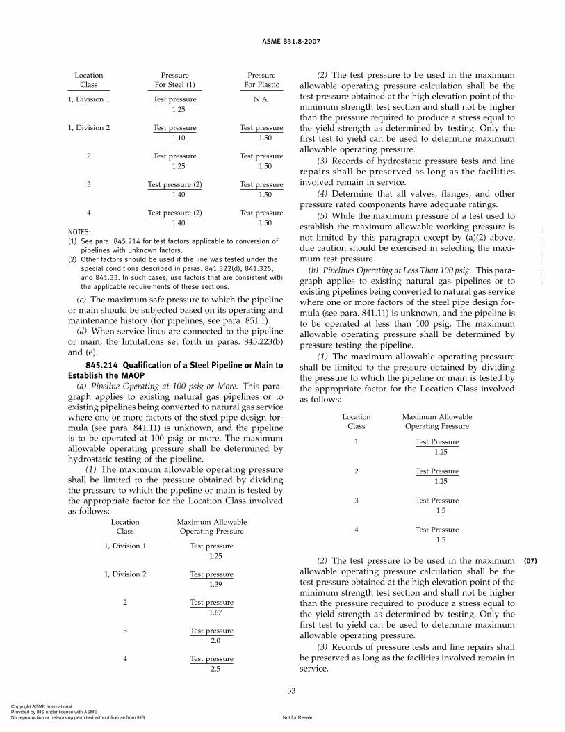
ASME B31.8-2007
Location Pressure PressureClass For Steel (1) For Plastic
1, Division 1 Test pressure N.A.1.25
1, Division 2 Test pressure Test pressure1.10 1.50
2 Test pressure Test pressure1.25 1.50
3 Test pressure (2) Test pressure1.40 1.50
4 Test pressure (2) Test pressure1.40 1.50
NOTES:(1) See para. 845.214 for test factors applicable to conversion of
pipelines with unknown factors.(2) Other factors should be used if the line was tested under the
special conditions described in paras. 841.322(d), 841.325,and 841.33. In such cases, use factors that are consistent withthe applicable requirements of these sections.
(c) The maximum safe pressure to which the pipelineor main should be subjected based on its operating andmaintenance history (for pipelines, see para. 851.1).
(d) When service lines are connected to the pipelineor main, the limitations set forth in paras. 845.223(b)and (e).
845.214 Qualification of a Steel Pipeline or Main toEstablish the MAOP
(a) Pipeline Operating at 100 psig or More. This para-graph applies to existing natural gas pipelines or toexisting pipelines being converted to natural gas servicewhere one or more factors of the steel pipe design for-mula (see para. 841.11) is unknown, and the pipelineis to be operated at 100 psig or more. The maximumallowable operating pressure shall be determined byhydrostatic testing of the pipeline.
(1) The maximum allowable operating pressureshall be limited to the pressure obtained by dividingthe pressure to which the pipeline or main is tested bythe appropriate factor for the Location Class involvedas follows:
Location Maximum AllowableClass Operating Pressure
1, Division 1 Test pressure1.25
1, Division 2 Test pressure1.39
2 Test pressure1.67
3 Test pressure2.0
4 Test pressure2.5
53
(2) The test pressure to be used in the maximumallowable operating pressure calculation shall be thetest pressure obtained at the high elevation point of theminimum strength test section and shall not be higherthan the pressure required to produce a stress equal tothe yield strength as determined by testing. Only thefirst test to yield can be used to determine maximumallowable operating pressure.
(3) Records of hydrostatic pressure tests and linerepairs shall be preserved as long as the facilitiesinvolved remain in service.
(4) Determine that all valves, flanges, and otherpressure rated components have adequate ratings.
(5) While the maximum pressure of a test used toestablish the maximum allowable working pressure isnot limited by this paragraph except by (a)(2) above,due caution should be exercised in selecting the maxi-mum test pressure.
(b) Pipelines Operating at Less Than 100 psig. This para-graph applies to existing natural gas pipelines or toexisting pipelines being converted to natural gas servicewhere one or more factors of the steel pipe design for-mula (see para. 841.11) is unknown, and the pipeline isto be operated at less than 100 psig. The maximumallowable operating pressure shall be determined bypressure testing the pipeline.
(1) The maximum allowable operating pressureshall be limited to the pressure obtained by dividingthe pressure to which the pipeline or main is tested bythe appropriate factor for the Location Class involvedas follows:
Location Maximum AllowableClass Operating Pressure
1 Test Pressure1.25
2 Test Pressure1.25
3 Test Pressure1.5
4 Test Pressure1.5
(2) The test pressure to be used in the maximumallowable operating pressure calculation shall be thetest pressure obtained at the high elevation point of theminimum strength test section and shall not be higherthan the pressure required to produce a stress equal tothe yield strength as determined by testing. Only thefirst test to yield can be used to determine maximumallowable operating pressure.
(3) Records of pressure tests and line repairs shallbe preserved as long as the facilities involved remain inservice.
(07)
Copyright ASME International Provided by IHS under license with ASME
Not for ResaleNo reproduction or networking permitted without license from IHS
--`,,```,,,,````-`-`,,`,,`,`,,`---

ASME B31.8-2007
(4) Determine that all valves, flanges, and otherpressure rated components have adequate ratings.
(5) Although the maximum pressure of a test uti-lized to establish the maximum allowable working pres-sure is not limited by this paragraph except by (b)(2)above, due caution should be exercised in selecting themaximum test pressure.
845.22 Control and Limiting of Gas Pressure inHigh-Pressure Steel, Ductile Iron, Cast Iron, or PlasticDistribution Systems
845.221 Each high-pressure distribution systemor main, supplied from a source of gas that is at a higherpressure than the maximum allowable operating pres-sure for the system, shall be equipped with pressure-regulating devices of adequate capacity and designedto meet the pressure, load, and other service conditionsunder which they will operate or to which they may besubjected.
845.222 In addition to the pressure-regulatingdevices prescribed in para. 845.221, a suitable methodshall be provided to prevent accidental overpressuringof a high-pressure distribution system.
Suitable types of protective devices to prevent over-pressuring of high-pressure distribution systemsinclude
(a) relief valves as prescribed in paras. 845.212(a)and (b)
(b) weight-loaded relief valves(c) a monitoring regulator installed in series with the
primary pressure regulator(d) a series regulator installed upstream from the pri-
mary regulator and set to limit the pressure on the inletof the primary regulator continuously to the maximumallowable operating pressure of the distribution systemor less
(e) an automatic shutoff device installed in series withthe primary pressure regulator and set to shut off whenthe pressure on the distribution system reaches the maxi-mum allowable operating pressure or less. This devicemust remain closed until manually reset. It should notbe used where it might cause an interruption in serviceto a large number of customers.
(f) spring-loaded, diaphragm-type relief valves
845.223 Maximum Allowable Operating Pressurefor High-Pressure Distribution Systems. This pressureshall be the maximum pressure to which the system canbe subjected in accordance with the requirements of thisCode. It shall not exceed
(a) the design pressure of the weakest element of thesystem as defined in para. 805.212
(b) 60 psig if the service lines in the system are notequipped with series regulators or other pressure-limiting devices as prescribed in para. 845.243
54
(c) 25 psig in cast iron systems having caulked belland spigot joints, which have not been equipped withbell joint clamps or other effective leak sealing methods
(d) the pressure limits to which any joint could besubjected without possibility of parting
(e) 2 psig in high-pressure distribution systemsequipped with service regulators not meeting therequirements of para. 845.241 and that do not have anoverpressure protective device as required in para.845.242
(f) the maximum safe pressure to which the systemshould be subjected based on its operation and mainte-nance history
845.23 Control and Limiting of Gas Pressure inLow-Pressure Distribution Systems
845.231 Each low-pressure distribution systemor low-pressure main supplied from a gas source thatis at a higher pressure than the maximum allowableoperating pressure for the low-pressure system shall beequipped with pressure-regulating devices of adequatecapacity. These devices must be designed to meet thepressure, load, and other service conditions under whichthey will have to operate.
845.232 In addition to the pressure-regulatingdevices prescribed in para. 845.231, a suitable deviceshall be provided to prevent accidental overpressuring.Suitable types of protective devices to prevent overpres-suring of low-pressure distribution systems include
(a) a liquid seal relief device that can be set to openaccurately and consistently at the desired pressure
(b) weight-loaded relief valves(c) an automatic shutoff device as described in para.
845.222(e)(d) a pilot-loaded, back-pressure regulator as
described in para. 845.212(b)(e) a monitoring regulator as described in para.
845.222(c)(f) a series regulator as described in para. 845.222(d)
845.233 Maximum Allowable Operating Pressurefor Low-Pressure Distribution Systems. The maximumallowable operating pressure for a low-pressure distri-bution system shall not exceed either of the following:
(a) a pressure that would cause the unsafe operationof any connected and properly adjusted low-pressuregas burning equipment
(b) a pressure of 2 psig
845.234 Conversion of Low-Pressure DistributionSystems to High-Pressure Distribution Systems
(a) Before converting a low-pressure distribution sys-tem to a high-pressure distribution system, it is requiredthat the following factors be considered:
(1) the design of the system including kinds ofmaterial and equipment used
Copyright ASME International Provided by IHS under license with ASME
Not for ResaleNo reproduction or networking permitted without license from IHS
--`,,```,,,,````-`-`,,`,,`,`,,`---
ASME B31.8-2007
(2) past maintenance records including results ofany previous leakage surveys
(b) Before increasing the pressure the following steps(not necessarily in sequence shown) shall be taken:
(1) Make a leakage survey and repair leaks found.(2) Reinforce or replace parts of the system found
to be inadequate for the higher operating pressures.(3) Install a service regulator on each service line,
and test each regulator to determine that it is function-ing. In some cases it may be necessary to raise the pres-sure slightly to permit proper operation of the serviceregulators.
(4) Isolate the system from adjacent low-pressuresystems.
(5) At bends or offsets in coupled or bell and spigotpipe, reinforce or replace anchorages determined to beinadequate for the higher pressures.
(c) The pressure in the system being converted shallbe increased by steps, with a period to check the effectof the previous increase before making the next increase.The desirable magnitude of each increase and the lengthof the check period will vary depending on conditions.The objective of this procedure is to afford an opportu-nity to discover any unknown open and unregulatedconnections to adjacent low-pressure systems or to indi-vidual customers before excessive pressures are reached.
845.24 Control and Limiting of the Pressure of GasDelivered to Domestic, Small Commercial, and SmallIndustrial Customers From High-Pressure DistributionSystems
NOTE: When the pressure of the gas and the demand by thecustomer are greater than those applicable under the provisionsof para. 845.24, the requirements for control and limiting of thepressure of gas delivered are included in para. 845.1.
845.241 If the maximum allowable operatingpressure of the distribution system is 60 psig or less,and a service regulator having the characteristics listedbelow is used, no other pressure-limiting device isrequired:
(a) a pressure regulator capable of reducing distribu-tion line pressure, psi, to pressures recommended forhousehold appliances, inches of water column
(b) a single port valve with orifice diameter no greaterthan that recommended by the manufacturer for themaximum gas pressure at the regulator inlet
(c) a valve seat made of resilient material designedto withstand abrasion of the gas, impurities in gas, andcutting by the valve, and designed to resist permanentdeformation when it is pressed against the valve port
(d) pipe connections to the regulator not exceedingNPS 2
(e) the capability under normal operating conditionsof regulating the downstream pressure within the neces-sary limits of accuracy and of limiting the buildup ofpressure under no-flow conditions to no more than 50%
55
over the normal discharge pressure maintained underflow conditions
(f) a self-contained service regulator with no externalstatic or control lines
845.242 If the maximum allowable operatingpressure of the distribution system is 60 psig or less,and a service regulator not having all of the characteris-tics listed in para. 845.241 is used, or if the gas containsmaterials that seriously interfere with the operation ofservice regulators, suitable protective devices shall beinstalled to prevent unsafe overpressuring of the cus-tomer’s appliances, should the service regulator fail.Some of the suitable types of protective devices to pre-vent overpressuring of the customers’ appliances are
(a) a monitoring regulator(b) a relief valve(c) an automatic shutoff deviceThese devices may be installed as an integral part of
the service regulator or as a separate unit.
845.243 If the maximum allowable operatingpressure of the distribution system exceeds 60 psig, suit-able methods shall be used to regulate and limit thepressure of the gas delivered to the customer to themaximum safe value. Such methods may include
(a) a service regulator having the characteristics listedin para. 845.241 and a secondary regulator locatedupstream from the service regulator. In no case shall thesecondary regulator be set to maintain a pressure higherthan 60 psi. A device shall be installed between thesecondary regulator and the service regulator to limitthe pressure on the inlet of the service regulator to 60 psior less in case the secondary regulator fails to functionproperly. This device may be either a relief valve or anautomatic shutoff that shuts if the pressure on the inletof the service regulator exceeds the set pressure (60 psior less) and remains closed until manually reset.
(b) a service regulator and a monitoring regulator setto limit to a maximum safe value the pressure of thegas delivered to the customer
(c) a service regulator with a relief valve vented tothe outside atmosphere, with the relief valve set to openso that the pressure of gas going to the customer shallnot exceed a maximum safe value. The relief valve maybe either built into the service regulator or may be aseparate unit installed downstream from the service reg-ulator. This combination may be used alone only in caseswhere the inlet pressure on the service regulator doesnot exceed the manufacturer’s safe working pressurerating of the service regulator, and it is not recommendedfor use where the inlet pressure on the service regulatorexceeds 125 psi. For higher inlet pressures, the methodin para. 845.243(a) or (b) should be used.
845.3 Requirements for Design of Pressure Reliefand Pressure-Limiting Installations
845.31 Pressure relief or pressure-limiting devicesexcept rupture disks shall
Copyright ASME International Provided by IHS under license with ASME
Not for ResaleNo reproduction or networking permitted without license from IHS
--`,,```,,,,````-`-`,,`,,`,`,,`---

ASME B31.8-2007
(a) be constructed of materials such that the operationof the device will not normally be impaired by corrosionof external parts by the atmosphere or internal partsby gas
(b) have valves and valve seats that are designed notto stick in a position that will make the device inopera-tive and result in failure of the device to perform in themanner for which it was intended
(c) be designed and installed so that they can bereadily operated to determine if the valve is free, canbe tested to determine the pressure at which they willoperate, and can be tested for leakage when in the closedposition.
845.311 Rupture discs shall meet the require-ments for design as set out in BPV Code, Section VIII,Division 1.
845.32 The discharge stacks, vents, or outlet portsof all pressure relief devices shall be located where gascan be discharged into the atmosphere without unduehazard. Consideration should be given to all exposuresin the immediate vicinity. Where required to protectdevices, the discharge stacks or vents shall be protectedwith rain caps to preclude the entry of water.
845.33 The size of the openings, pipe, and fittingslocated between the system to be protected and thepressure-relieving device and the vent line shall be ofadequate size to prevent hammering of the valve andto prevent impairment of relief capacity.
845.34 Precautions shall be taken to prevent unau-thorized operation of any stop valve that will make apressure relief valve inoperative. This provision shallnot apply to valves that will isolate the system underprotection from its source of pressure. Acceptable meth-ods for complying with this provision are as follows:
(a) Lock the stop valve in the open position. Instructauthorized personnel of the importance of not inadver-tently leaving the stop valve closed and of being presentduring the entire period that the stop valve is closed sothat they can lock it in the open position before theyleave the location.
(b) Install duplicate relief valves, each having ade-quate capacity by itself to protect the system, andarrange the isolating valves or three-way valve so thatmechanically it is possible to render only one safetydevice inoperative at a time.
845.35 Precautions shall be taken to prevent unau-thorized operation of any valve that will make pressure-limiting devices inoperative. This provision applies toisolating valves, bypass valves, and valves on control orfloat lines that are located between the pressure-limitingdevice and the system that the device protects. A methodsimilar to para. 845.34(a) shall be considered acceptablein complying with this provision.
56
845.36(a) When a monitoring regulator, series regulator, sys-
tem relief, or system shutoff is installed at a districtregulator station to protect a piping system from over-pressuring, the installation shall be designed andinstalled to prevent any single incident, such as an explo-sion in a vault or damage by a vehicle, from affectingthe operation of both the overpressure protective deviceand the district regulator. (See paras. 846 and 847.)
(b) Special attention shall be given to control lines.All control lines shall be protected from falling objects,excavations by others, or other foreseeable causes ofdamage and shall be designed and installed to preventdamage to any one control line from making both thedistrict regulator and the overpressure protective deviceinoperative.
845.4 Capacity of Pressure-Relieving andPressure-Limiting Station and Devices
845.41 Required Capacity of Pressure-Relieving andPressure-Limiting Stations
845.411 Each pressure relief station, pressure-limiting station, or group of such stations installed toprotect a piping system or pressure vessel shall havesufficient capacity and shall be set to operate to preventthe pressure from exceeding the following levels.
(a) Systems With Pipe or Pipeline Components Operatingat Hoop Stress Levels Over 72% of the SMYS. The requiredcapacity is the maximum allowable operating pressureplus 4%.
(b) Systems With Pipe or Pipeline Components Operatingat Hoop Stress Levels at or Below 72% of the SMYS OtherThan in Low-Pressure Distribution Systems. The requiredcapacity is the lesser of the following two items:
(1) the maximum allowable operating pressureplus 10%
(2) the pressure that produces a hoop stress of 75%of the specified minimum yield strength
(c) Low-Pressure Distribution Systems. The requiredcapacity is a pressure that would cause the unsafe opera-tion of any connected and properly adjusted gas burningequipment.
845.412 When more than one pressure-regulat-ing or compressor station feeds into the pipeline or dis-tribution system and pressure relief devices are installedat such stations, the relieving capacity at the remotestation may be taken into account in sizing the reliefdevices at each station. In doing this, however, theassumed remote relieving capacity must be limited tothe capacity of the piping system to transmit gas to theremote location or to the capacity of the remote reliefdevice, whichever is less.
(07)
Copyright ASME International Provided by IHS under license with ASME
Not for ResaleNo reproduction or networking permitted without license from IHS
--`,,```,,,,````-`-`,,`,,`,`,,`---

ASME B31.8-2007
845.42 Proof of Adequate Capacity and SatisfactoryPerformance of Pressure-Limiting and Pressure ReliefDevices
845.421 Where the safety device consists of anadditional regulator that is associated with or functionsin combination with one or more regulators in a seriesarrangement to control or limit the pressure in a pipingsystem, suitable checks shall be made. These checksshall be conducted to determine that the equipment willoperate in a satisfactory manner to prevent any pressurein excess of the established maximum allowableoperating pressure of the system, should any one of theassociated regulators malfunction or remain in the wide-open position.
845.5 Instrument, Control, and Sample Piping
(a) Scope(1) The requirements given in this section apply to
the design of instrument, control, and sampling pipingfor safe and proper operation of the piping itself anddo not cover design of piping to secure proper function-ing of instruments for which the piping is installed.
(2) This section does not apply to permanentlyclosed piping systems, such as fluid-filled, temperature-responsive devices.
(b) Materials and Design(1) The materials employed for valves, fittings, tub-
ing, and piping shall be designed to meet the particularconditions of service.
(2) Takeoff connections and attaching bosses, fit-tings, or adapters shall be made of suitable material andshall be capable of withstanding the maximum servicepressure and temperature of the piping or equipmentto which they are attached. They shall be designed tosatisfactorily withstand all stresses without failure byfatigue.
(3) A shutoff valve shall be installed in each takeoffline as near as practicable to the point of takeoff. Blow-down valves shall be installed where necessary for thesafe operation of piping, instruments, and equipment.
(4) Brass pipe or copper pipe or tubing shall notbe used for metal temperatures greater than 400°F.
(5) Piping subject to clogging from solids or depos-its shall be provided with suitable connections forcleaning.
(6) Pipe or tubing required under this section maybe specified by the manufacturers of the instrument,control apparatus, or sampling device, provided that thesafety of the pipe or tubing as installed is at least equalto that otherwise required under the Code.
(7) Piping that may contain liquids shall be pro-tected by heating or other suitable means from damagedue to freezing.
(8) Piping in which liquids may accumulate shallbe provided with drains or drips.
57
(9) The arrangement of piping and supports shallbe designed to provide not only for safety underoperating stresses, but also to provide protection for thepiping against detrimental sagging, external mechanicalinjury, abuse, and damage due to unusual service condi-tions other than those connected with pressure, temper-ature, and service vibration.
(10) Suitable precautions shall be taken to protectagainst corrosion. (See para. 863.)
(11) Joints between sections of tubing and/or pipe,between tubing and/or pipe and valves or fittings shallbe made in a manner suitable for the pressure and tem-perature conditions, such as by means of flared, flareless,and compression-type fittings, or equal, or they maybe of the brazed, screwed, or socket-welded type. Ifscrewed-end valves are to be used with flared, flareless,or compression-type fittings, adapters are required.
Slip-type expansion joints shall not be used; expansionshall be compensated for by providing flexibility withinthe piping or tubing system itself.
(12) Plastic shall not be used where operating tem-peratures exceed limitations shown in paras. 842.32(b)and 842.33(b).
(13) Plastic piping shall not be painted. If identifica-tion other than that already provided by the manufactur-er’s marking is required, it shall be accomplished byother means.
845.6 Uprating
This section of the Code prescribes minimum require-ments for uprating pipelines or mains to higher maxi-mum allowable operating pressures.
845.61 General(a) A higher maximum allowable operating pressure
established under this section may not exceed the designpressure of the weakest element in the segment to beuprated. It is not intended that the requirements of thisCode be applied retroactively to such items as roadcrossings, fabricated assemblies, minimum cover, andvalve spacings. Instead, the requirements for these itemsshall meet the criteria of the operating company beforethe uprating is performed.
(b) A plan shall be prepared for uprating that shallinclude a written procedure that will ensure compliancewith each applicable requirement of this section.
(c) Before increasing the maximum allowableoperating pressure of a segment that has been operatingat a pressure less than that determined by para. 845.213,the following investigative and corrective measuresshall be taken:
(1) The design, initial installation, method, anddate of previous testing, Location classes, materials, andequipment shall be reviewed to determine that the pro-posed increase is safe and consistent with the require-ments of this Code.
Copyright ASME International Provided by IHS under license with ASME
Not for ResaleNo reproduction or networking permitted without license from IHS
--`,,```,,,,````-`-`,,`,,`,`,,`---

ASME B31.8-2007
(2) The condition of the line shall be determinedby leakage surveys, other field inspections, and exami-nation of maintenance records.
(3) Repairs, replacements, or alterations disclosedto be necessary by subparas. (c)(1) and (c)(2) above shallbe made prior to the uprating.
(d) A new test according to the requirements of thisCode should be considered if satisfactory evidence isnot available to ensure safe operation at the proposedmaximum allowable operating pressure.
(e) When gas upratings are permitted under paras.845.62, 845.63, 845.64, and 845.65, the gas pressure shallbe increased in increments, with a leak survey performedafter each incremental increase. The number of incre-ments shall be determined by the operator after consid-ering the total amount of the pressure increase, the stresslevel at the final maximum allowable operating pressure,the known condition of the line, and the proximity ofthe line to other structures. The number of incrementsshall be sufficient to ensure that any leaks are detectedbefore they can create a potential hazard. Potentiallyhazardous leaks discovered shall be repaired before fur-ther increasing the pressure. A final leak survey shall beconducted at the higher maximum allowable operatingpressure.
(f) Records for uprating, including each investigationrequired by this section, corrective action taken, andpressure test conducted, shall be retained as long as thefacilities involved remain in service.
845.62 Uprating Steel Pipelines or Mains to a Pres-sure That Will Produce a Hoop Stress of 30% or Moreof SMYS. The maximum allowable operating pressuremay be increased after compliance with para. 845.61(c)and one of the following provisions:
(a) If the physical condition of the line as determinedby para. 845.61(c) indicates the line is capable of with-standing the desired higher operating pressure, is ingeneral agreement with the design requirements of thisCode, and has previously been tested to a pressure equalto or greater than that required by this Code for a newline for the proposed maximum allowable operatingpressure, the line may be operated at the higher maxi-mum allowable operating pressure.
(b) If the physical condition of the line as determinedby para. 845.61(c) indicates that the ability of the line towithstand the higher maximum operating pressure hasnot been satisfactorily verified or that the line has notbeen previously tested to the levels required by thisCode for a new line for the proposed higher maximumallowable operating pressure, the line may be operatedat the higher maximum allowable operating pressure ifit shall successfully withstand the test required by thisCode for a new line to operate under the same condi-tions.
(c) If the physical condition of the line as determinedby para. 845.61(c) verifies its capability of operating at a
58
higher pressure, a higher maximum allowable operatingpressure may be established according to para. 845.213using as a test pressure the highest pressure to whichthe line has been subjected, either in a strength test orin actual operation.
(d) If it is necessary to test a pipeline or main beforeit can be uprated to a higher maximum allowableoperating pressure, and if it is not practical to test theline either because of the expense or difficulties createdby taking it out of service or because of other operatingconditions, a higher maximum allowable operatingpressure may be established in Location Class 1 asfollows.
(1) Perform the requirements of para. 845.61(c).(2) Select a new maximum allowable operating
pressure consistent with the condition of the line andthe design requirements of this Code, provided
(a) the new maximum allowable operating pres-sure does not exceed 80% of that permitted for a newline to operate under the same conditions
(b) the pressure is increased in increments as pro-vided in para. 845.61(e)
845.63 Uprating Steel or Plastic Pipelines to a Pres-sure That Will Produce a Hoop Stress Less Than 30% ofSMYS
(a) This applies to high-pressure steel mains and pipe-lines where the higher maximum allowable operatingpressure is less than that required to produce a hoopstress of 30% of the specified minimum yield strengthof the pipe and to all high-pressure plastic distributionsystems. If the higher maximum allowable operatingpressure of a steel pipeline or main is producing a hoopstress level more than 30% of the specified minimumyield strength of the pipe, the provisions of para. 845.62shall apply.
(b) Before increasing the maximum allowableoperating pressure of a system that has been operatingat less than the applicable maximum pressure to a highermaximum allowable operating pressure, the followingfactors shall be considered:
(1) the physical condition of the line as determinedby para. 845.61(c)
(2) information from the manufacturer or supplierdetermining that each component of a plastic system iscapable of performing satisfactorily at the higherpressure.
(c) Before increasing the pressure, the following stepsshall be taken:
(1) Install suitable devices on the service lines toregulate and limit the pressure of the gas in accordancewith para. 845.243 if the new maximum allowableoperating pressure is to be over 60 psi.
(2) Adequately reinforce or anchor offsets, bends,and dead ends in coupled pipe to avoid movement ofthe pipe should the offset, bend, or dead end be exposedin an excavation.
Copyright ASME International Provided by IHS under license with ASME
Not for ResaleNo reproduction or networking permitted without license from IHS
--`,,```,,,,````-`-`,,`,,`,`,,`---

ASME B31.8-2007
(3) Increase pressure in increments as provided inpara. 845.61(e).
845.64 Uprating a Ductile Iron High-Pressure Mainor System to a New and Higher Maximum AllowableOperating Pressure
(a) The maximum allowable operating pressure of aductile iron main or system shall not be increased to apressure in excess of that permitted in para. 842.211.Where records are not complete enough to permit thedirect application of para. 842.211, the following proce-dures shall be used.
(1) Laying Condition. Where the original laying con-ditions cannot be ascertained, it shall be assumed thatCondition D (pipe supported on blocks, tamped backfill)exists for cast iron pipe and Condition B (pipe laid with-out blocks, tamped backfill) exists for ductile iron pipe.
(2) Cover. Unless the actual maximum cover depthis known with certainty, it shall be determined byexposing the main or system at three or more pointsand making actual measurements. The main or systemshall be exposed in areas where the cover depth is mostlikely to be greatest. The greatest measured cover depthshall be used for computations.
(3) Nominal Wall Thickness. Unless the nominalthickness is known with certainty, it shall be determinedwith ultrasonic measuring devices. The average of allmeasurements taken shall be increased by the allowanceindicated in the following table:
Allowance, in.
Cast Iron PipeDuctile
Nominal Pit Cast Centrifugally Cast IronPipe Size Pipe Pipe Pipe
3–8 0.075 0.065 0.06510–12 0.08 0.07 0.0714–24 0.08 0.08 0.07530–42 0.09 0.09 0.075
48 0.09 0.09 0.0854–60 0.09 . . . . . .
The nominal wall thickness of cast iron shall be thestandard thickness listed in Table 10 or Table 11 —whichever is applicable — of AWWA C101 that is nearestthe value obtained. The nominal wall thickness of ductileiron shall be the standard thickness listed in Table 6 ofANSI/AWWA C150/A21.50 nearest the value obtained.
(4) Manufacturing Process. Unless the cast iron pipemanufacturing process is known with certainty, it shallbe assumed to be pit cast pipe having a bursting tensilestrength, S, of 11,000 psi and a modulus of rupture, R,of 31,000 psi.
(b) Before increasing the maximum allowableoperating pressure, the following measures shall betaken:
(1) Review the physical condition as required bypara. 845.61(c).
59
(2) Adequately reinforce or anchor offsets, bends,and dead ends in coupled or bell and spigot pipe toavoid movement of the pipe, should the offset, bend, ordead end be exposed by excavation.
(3) Install suitable devices on the service lines toregulate and limit the pressure of the gas in accordancewith para. 845.243 if the new and higher maximumallowable operating pressure is to be over 60 psig.
(c) If after compliance with paras. 845.64(a) and (b),it is established that the main system is capable of safelywithstanding the proposed new and higher maximumallowable operating pressure, the pressure shall beincreased as provided in para. 845.61(e).
845.65 Uprating a Distribution System That Has BeenOperating at Inches of Water (Low-Pressure) to a HigherPressure
(a) In addition to the precautions outlined in para.845.61(c) and the applicable requirements contained inparas. 845.63 and 845.64, the following steps must betaken.
(1) Install pressure-regulating devices at each cus-tomer’s meter.
(2) Verify that the segment being uprated is physi-cally disconnected from all segments of line that willcontinue to operate at inches of water.
(b) After performing the steps outlined in (a) above,the pressure shall be increased in increments as outlinedin para. 845.61(e). After the first incremental increase,however, steps shall be taken to verify that the custom-er’s regulators are performing satisfactorily.
846 VALVES3
846.1 Required Spacing of Valves
846.11 Transmission Lines Onshore block valvesshall be installed in new transmission pipelines at thetime of construction for the purpose of isolating thepipeline for maintenance and for response to operatingemergencies. When determining the placement of suchvalves for sectionalizing the pipeline, primary consider-ation shall be given to locations that provide continuousaccessibility to the valves.
(a) In determining the number and spacing of valvesto be installed, the operator shall perform an assessmentthat gives consideration to factors such as
(1) the amount of gas released due to repair andmaintenance blowdowns, leaks, or ruptures
(2) the time to blow down an isolated section(3) the impact in the area of gas release (e.g., nui-
sance and any hazard resulting from prolonged blow-downs)
(4) continuity of service(5) operating and maintenance flexibility of the
system
3 See paras. 849.12 and 849.13 for provisions covering valves inservice lines.
(07)
Copyright ASME International Provided by IHS under license with ASME
Not for ResaleNo reproduction or networking permitted without license from IHS
--`,,```,,,,````-`-`,,`,,`,`,,`---

ASME B31.8-2007
(6) future development in the vicinity of thepipeline
(7) significant conditions that may adversely affectthe operation and security of the line
(b) In lieu of (a) above, the following maximum spac-ing between valves shall be used:
(1) 20 miles in areas of predominantly LocationClass 1
(2) 15 miles in areas of predominantly LocationClass 2
(3) 10 miles in areas of predominantly LocationClass 3
(4) 5 miles in areas of predominantly LocationClass 4
The spacing defined above may be adjusted to permita valve to be installed in a location that is moreaccessible.
846.12 Valves on distribution mains, whether foroperating or emergency purposes, shall be spaced asfollows:
(a) High-Pressure Distribution Systems. Valves shall beinstalled in high-pressure distribution systems in acces-sible locations to reduce the time to shut down a sectionof main in an emergency. In determining the spacing ofthe valves, consideration should be given to theoperating pressure and size of the mains and local physi-cal conditions as well as the number and type of consum-ers that might be affected by a shutdown.
(b) Low-Pressure Distribution Systems. Valves may beused on low-pressure distribution systems but are notrequired except as specified in para. 846.22(a).
846.2 Location of Valves
846.21 Transmission Valves(a) Sectionalizing block valves shall be accessible and
protected from damage and tampering. If a blowdownvalve is involved, it shall be located where the gas canbe blown to the atmosphere without undue hazard.
(b) Sectionalizing valves may be installed aboveground, in a vault, or buried. In all installations anoperating device to open or close the valve shall bereadily accessible to authorized persons. All valves shallbe suitably supported to prevent settlement or move-ment of the attached piping.
(c) Blowdown valves shall be provided so that eachsection of pipeline between main line valves can beblown down. The sizes and capacity of the connectionsfor blowing down the line shall be such that underemergency conditions the section of line can be blowndown as rapidly as is practicable.
(d) This Code does not require the use of automaticvalves nor does the Code imply that the use of automaticvalves presently developed will provide full protectionto a piping system. Their use and installation shall beat the discretion of the operating company.
60
846.22 Distribution System Valves(a) A valve shall be installed on the inlet piping of
each regulator station controlling the flow or pressureof gas in a distribution system. The distance between thevalve and the regulator or regulators shall be sufficient topermit the operation of the valve during an emergency,such as a large gas leak or a fire in the station.
(b) Valves on distribution mains, whether foroperating or emergency purposes, shall be located in amanner that will provide ready access and facilitate theiroperation during an emergency. Where a valve isinstalled in a buried box or enclosure, only ready accessto the operating stem or mechanism is implied. The boxor enclosure shall be installed in a manner to avoidtransmitting external loads to the main.
847 VAULTS
847.1 Structural Design Requirements
Underground vaults or pits for valves, pressure-reliev-ing, pressure-limiting or pressure-regulating stations,etc., shall be designed and constructed in accordancewith the following provisions:
(a) Vaults and pits shall be designed and constructedin accordance with good structural engineering practiceto meet the loads that may be imposed on them.
(b) Sufficient working space shall be provided so thatall of the equipment required in the vault can be properlyinstalled, operated, and maintained.
(c) In the design of vaults and pits for pressure-limiting, pressure-relieving, and pressure-regulatingequipment, consideration shall be given to the protec-tion of the installed equipment from damage, such asthat resulting from an explosion within the vault or pitthat may cause portions of the roof or cover to fall intothe vault.
(d) Pipe entering and within regulator vaults or pitsshall be steel for NPS 10 and smaller sizes, except thatcontrol and gage piping may be copper. Where pipingextends through the vault or pit structure, provisionshall be made to prevent the passage of gases or liquidsthrough the opening and to avert strains in the piping.Equipment and piping shall be suitably sustained bymetal, masonry, or concrete supports. The control pipingshall be placed and supported in the vault or pit sothat its exposure to injury or damage is reduced to aminimum.
(e) Vault or pit openings shall be located so as tominimize the hazards of tools or other objects falling onthe regulator, piping, or other equipment. The controlpiping and the operating parts of the equipmentinstalled shall not be located under a vault or pit openingwhere workmen can step on them when entering orleaving the vault or pit, unless such parts are suitablyprotected.
Copyright ASME International Provided by IHS under license with ASME
Not for ResaleNo reproduction or networking permitted without license from IHS
--`,,```,,,,````-`-`,,`,,`,`,,`---

ASME B31.8-2007
(f) Whenever a vault or pit opening is to be locatedabove equipment that could be damaged by a fallingcover, a circular cover should be installed, or other suit-able precautions should be taken.
847.2 Accessibility
Accessibility shall be considered in selecting a site fora vault. Some of the important factors to consider inselecting the location of a vault are as follows:
(a) Exposure to Traffic. The location of vaults in streetintersections or at points where traffic is heavy or denseshould be avoided.
(b) Exposure to Flooding. Vaults should not be locatedat points of minimum elevation, near catch basins, orwhere the access cover will be in the course of surfacewaters.
(c) Exposure to Adjacent Subsurface Hazards. Vaultsshould be located as far as is practical from water, elec-tric, steam, or other facilities.
847.3 Vault Sealing, Venting, and Ventilation
Underground vaults and closed top pits containingeither a pressure-regulating or reduction station, or apressure-limiting or relieving station shall be sealed,vented, or ventilated as follows:
(a) When the internal volume exceeds 200 ft3, suchvaults or pits shall be ventilated with two ducts eachhaving at least the ventilating effect of an NPS 4 pipe.
(b) The ventilation provided shall be sufficient to min-imize the possible formation of a combustible atmo-sphere in the vault or pit. Vents associated with thepressure-regulating or pressure-relieving equipmentmust not be connected to the vault or pit ventilation.
(c) The ducts shall extend to a height above gradeadequate to disperse any gas–air mixtures that mightbe discharged. The outside end of the ducts shall beequipped with a suitable weatherproof fitting or venthead designed to prevent foreign matter from enteringor obstructing the duct. The effective area of the openingin such fittings or vent heads shall be at least equal tothe cross-sectional area of an NPS 4 duct. The horizontalsection of the ducts shall be as short as practical andshall be pitched to prevent the accumulation of liquidsin the line. The number of bends and offsets shall bereduced to a minimum, and provisions shall be incorpo-rated to facilitate the periodic cleaning of the ducts.
(d) Such vaults or pits having an internal volumebetween 75 ft3 and 200 ft3 may be either sealed, vented,or ventilated. If sealed, all openings shall be equippedwith tight-fitting covers without open holes throughwhich an explosive mixture might be ignited. Meansshall be provided for testing the internal atmospherebefore removing the cover. If vented, the proper provi-sion to prevent external sources of ignition from reachingthe vault atmosphere must be provided. If ventilated,
61
the provisions of either (a), (b), and (c) above or (e)below shall apply.
(e) If vaults or pits referred to in (d) above are venti-lated by means of openings in the covers or gratings,and the ratio of the internal volume in cubic feet to theeffective ventilating area of the cover or grating in squarefeet is less than 20 to 1, no additional ventilation isrequired.
(f) Vaults or pits having an internal volume less than75 ft3 have no specific requirements.
847.4 Drainage and Waterproofing
(a) Provisions shall be made to minimize the entranceof water into vaults. Nevertheless, vault equipment shallalways be designed to operate safely, if submerged.
(b) No vault containing gas piping shall be connectedby means of a drain connection to any other substruc-ture, such as a sewer.
(c) Electrical equipment in vaults shall conform to therequirements of Class 1, Group D, of ANSI/NFPA 70.
848 CUSTOMERS’ METERS AND REGULATORS848.1 Location for Customers’ Meter and Regulator
Installations
(a) Customers’ meters and regulators may be locatedeither inside or outside of buildings, depending on localconditions, except that on service lines requiring seriesregulation, in accordance with para. 845.243(a), theupstream regulator shall be located outside of thebuilding.
(b) When installed within a building, the service regu-lator shall be in a readily accessible location near thepoint of gas service line entrance, and whenever practi-cal, the meters shall be installed at the same location.Neither meters nor regulators shall be installed in bed-rooms, closets, or bathrooms; under combustible stair-ways; in unventilated or inaccessible places; or closerthan 3 ft to sources of ignition, including furnaces andwater heaters. On service lines supplying large indus-trial customers or installations where gas is used athigher than standard service pressure, the regulatorsmay be installed at other readily accessible locations.
(c) When located outside of buildings, meters andservice regulators shall be installed in readily accessiblelocations where they will be reasonably protected fromdamage.
(d) Regulators requiring vents for their proper andeffective operation shall be vented to the outside atmo-sphere in accordance with the provisions of para. 848.33.Individual vents shall be provided for each regulator.
848.2 Operating Pressures for Customers’ MeterInstallations
Iron or aluminum case meters shall not be used at amaximum operating pressure higher than the manufac-turer’s rating for the meter. New tinned steel case meters
Copyright ASME International Provided by IHS under license with ASME
Not for ResaleNo reproduction or networking permitted without license from IHS
--`,,```,,,,````-`-`,,`,,`,`,,`---

ASME B31.8-2007
shall not be used at a pressure in excess of 50% of themanufacturer’s test pressure; rebuilt tinned steel casemeters shall not be used at a pressure in excess of 50%of the pressure used to test the meter after rebuilding.
848.3 Protection of Customers’ Meter and RegulatorInstallations From Damage
848.31 Meters and service regulators shall not beinstalled where rapid deterioration from corrosion orother causes is likely to occur, unless proven measuresare taken to protect against such deterioration.
848.32 A suitable protective device, such as a back-pressure regulator or a check valve, shall be installeddownstream of the meter if and as required under thefollowing conditions:
(a) If the nature of the utilization equipment is suchthat it may induce a vacuum at the meter, install a back-pressure regulator downstream from the meter.
(b) Install a check valve or equivalent if(1) the utilization equipment might induce a back-
pressure(2) the gas utilization equipment is connected to a
source of oxygen or compressed air(3) liquefied petroleum gas or other supplementary
gas is used as standby and might flow back into themeter. A three-way valve, installed to admit the standbysupply and at the same time shut off the regular supply,can be substituted for a check valve if desired.
848.33 All service regulator vents and relief vents,where required, shall terminate in the outside air in rain-and insect-resistant fittings. The open end of the ventshall be located where the gas can escape freely intothe atmosphere and away from any openings into thebuildings if a regulator failure resulting in the releaseof gas occurs. At locations where service regulatorsmight be submerged during floods, either a special anti-flood type breather vent fitting shall be installed or thevent line shall be extended above the height of theexpected flood waters.
848.34 Pits and vaults housing customers’ metersand regulators shall be designed to support vehiculartraffic when installed in the following locations:
(a) travelled portions of alleys, streets, and highways(b) driveways
848.4 Installation of Meters and Regulators
All meters and regulators shall be installed in such amanner as to prevent undue stresses on the connectingpiping and/or the meter. Lead (Pb) connections or otherconnections made of material that can be easily damagedshall not be used. The use of standard weight close (allthread) nipples is prohibited.
62
849 GAS SERVICE LINES
849.1 General Provisions Applicable to Steel,Copper, and Plastic Service Lines
849.11 Installation of Service Lines(a) Service lines shall be installed at a depth that will
protect them from excessive external loading and localactivities, such as gardening. It is required that a mini-mum of 12 in. of cover be provided in private propertyand a minimum of 18 in. of cover be provided in streetsand roads. Where these cover requirements cannot bemet due to existing substructures, less cover is permittedprovided such portions of these service lines that aresubject to excessive superimposed loads are cased orbridged or the pipe is appropriately strengthened.
(b) Service lines shall be properly supported at allpoints on undisturbed or well-compacted soil so thatthe pipe will not be subject to excessive external loadingby the backfill. The material used for the backfill shallbe free of rocks, building materials, etc., that might causedamage to the pipe or the protective coating.
(c) Where there is evidence of condensate in the gasin sufficient quantities to cause interruptions in the gassupply to the customer, the service line shall be gradedso as to drain into the main or to drips at the low pointsin the service line.
849.12 Types of Valves Suitable for Service LineValves
(a) Valves used as service line valves shall meet theapplicable requirements of paras. 810 and 831.1.
(b) The use of soft seat service line valves is not recom-mended when the design of the valves is such that expo-sure to excessive heat could adversely affect the abilityof the valve to prevent the flow of gas.
(c) A valve incorporated in a meter bar that permitsthe meter to be bypassed does not qualify under thisCode as a service line valve.
(d) Service line valves on high-pressure service lines,installed either inside buildings or in confined locationsoutside buildings where the blowing of gas would behazardous, shall be designed and constructed to mini-mize the possibility of the removal of the core of the valveaccidentally or willfully with ordinary household tools.
(e) The operating company shall make certain thatthe service line valves installed on high-pressure servicelines are suitable for this use either by making their owntests or by reviewing the tests made by the manufac-turers.
(f) On service lines designed to operate at pressuresin excess of 60 psig, the service line valves shall be theequivalent of a pressure-lubricated valve or a needle-type valve. Other types of valves may be used wheretests by the manufacturer or by the user indicate thatthey are suitable for this kind of service.
Copyright ASME International Provided by IHS under license with ASME
Not for ResaleNo reproduction or networking permitted without license from IHS
--`,,```,,,,````-`-`,,`,,`,`,,`---

ASME B31.8-2007
849.13 Location of Service Line Valves(a) Service line valves shall be installed on all new
service lines (including replacements) in a locationreadily accessible from the outside.
(b) Valves shall be located upstream of the meter ifthere is no regulator, or upstream of the regulator, ifthere is one.
(c) All service lines operating at a pressure greaterthan 10 psig and all service lines NPS 2 or larger shallbe equipped with a valve located on the service lineoutside of the building, except that whenever gas issupplied to a theater, church, school, factory, or otherbuilding where large numbers of persons assemble, anoutside valve will be required, regardless of the size ofthe service line or the service line pressure.
(d) Underground valves shall be located in a covereddurable curb box or standpipe designed to permit readyoperation of the valve. The curb box or standpipe shallbe supported independently of the service line.
849.14 Location of Service Line Connections to MainPiping. It is recommended that service lines be con-nected to either the top or the side of the main. Theconnection to the top of the main is preferred to mini-mize the possibility of dust and moisture being carriedfrom the main into the service line.
849.15 Testing of Service Lines After Construction
849.151 General Provisions. Each service lineshall be tested after construction and before being placedin service to demonstrate that it does not leak. The ser-vice line connection to the main need not be includedin this test if it is not feasible to do so.
849.152 Test Requirements(a) Service lines to operate at a pressure of less than
1 psig, which do not have a protective coating capableof temporarily sealing a leak, shall be given a standupair or gas pressure test at not less than 10 psig for atleast 5 min.
(b) Service lines to operate at a pressure of less than1 psig, which have a protective coating that might tem-porarily seal a leak, and all service lines to operate at apressure of 1 psig or more, shall be given a standup airor gas pressure test for at least 5 min at the proposedmaximum operating pressure or 90 psig, whichever isgreater. Service lines of steel, however, that are operatingat hoop stress levels of 20% or more of the specifiedminimum yield strength shall be tested in accordancewith the requirements for testing mains. (See para.841.3.)
(c) The requirements of (a) and (b) above shall applyto plastic service lines, except that plastic service linesshall be tested to at least 1.5 times the maximumoperating pressure, and the limitations on maximumtest pressure, temperature, and duration set forth inpara. 842.52 shall be observed.
63
849.2 Steel Service Lines
849.21 Design of Steel Service Lines(a) Steel pipe, when used for service lines, shall con-
form to the applicable requirements of Chapter I.(b) Steel service pipe shall be designed in accordance
with the requirements of paras. 841.11 and 841.121.Where the pressure is less than 100 psig, the steel servicepipe shall be designed for at least 100 psig pressure.
(c) Steel pipe used for service lines shall be installedin such a manner that the piping strain or external load-ing shall not be excessive.
(d) All underground steel service lines shall be joinedby threaded and coupled joints, compression-type fit-tings, or by qualified welding or brazing methods, proce-dures, and operators.
849.22 Installation of Steel Service Lines
849.221 Installation of Steel Service Lines in Bores(a) When coated steel pipe is to be installed as a ser-
vice line in a bore, care shall be exercised to preventdamage to the coating during installation.
(b) When a service line is to be installed by boring ordriving, and coated steel pipe is to be used, it shall notbe used as the bore pipe or drive pipe and left in theground as part of the service line unless it has beendemonstrated that the coating is sufficiently durable towithstand the boring or driving operation in the type ofsoil involved without significant damage to the coating.Where significant damage to the coating may result fromboring or driving, the coated service line should beinstalled in an oversized bore or casing pipe of sufficientdiameter to accommodate the service pipe.
(c) In exceptionally rocky soil, coated pipe shall notbe inserted through an open bore if significant damageto the coating is likely.
849.222 Installation of Service Lines Into or UnderBuildings
(a) Underground steel service lines, when installedbelow grade through the outer foundation wall of abuilding, shall be either encased in a sleeve or otherwiseprotected against corrosion. The service line and/orsleeve shall be sealed at the foundation wall to prevententry of gas or water into the building.
(b) Steel service lines, where installed undergroundunder buildings, shall be encased in a gas-tight conduit.When such a service line supplies the building it sub-tends, the conduit shall extend into a normally usableand accessible portion of the building. At the pointwhere the conduit terminates, the space between theconduit and the service line shall be sealed to preventthe possible entrance of any gas leakage. The casingshall be vented at a safe location.
849.3 Ductile Iron Service Lines
849.31 Use of Ductile Iron Service Lines. Whenused for service lines, ductile iron pipe shall meet the
Copyright ASME International Provided by IHS under license with ASME
Not for ResaleNo reproduction or networking permitted without license from IHS
--`,,```,,,,````-`-`,,`,,`,`,,`---

ASME B31.8-2007
applicable requirements of para. 842. Ductile iron pipemay be used for service lines except for the portion ofthe service line that extends through the building wall.Ductile iron service lines shall not be installed in unsta-ble soils or under buildings.
849.4 Plastic Service Lines
849.41 Design of Plastic Service Lines(a) Plastic pipe and tubing shall be used for service
lines only where the piping strain or external loadingwill not be excessive.
(b) Plastic pipe, tubing, cements, and fittings used forservice lines shall conform to the applicable require-ments of Chapter I.
(c) Plastic service lines shall be designed in accor-dance with the applicable requirements of para. 842.3.
(d) Plastic service lines shall be joined in accordancewith the applicable requirements of para. 842.39.
849.42 Installation of Plastic Service Lines(a) Plastic service lines shall be installed in accordance
with the applicable requirements of paras. 842.4 and849.11. Particular care must be exercised to prevent dam-age to plastic service line piping at the connection tothe main or other facility. Precautions shall be taken toprevent crushing or shearing of plastic piping due toexternal loading or settling of backfill and to preventdamage or pullout from the connection resulting fromthermal expansion or contraction. (See paras. 842.431and 842.432.)
(b) Notwithstanding the limitations imposed in para.842.43, a plastic service line may terminate above groundand outside the building, provided that
(1) the aboveground portion of the plastic serviceline is completely enclosed in a conduit or casing ofsufficient strength to provide protection from externaldamage and deterioration. Where a flexible conduit isused, the top of the riser must be attached to a solidsupport. The conduit or casing shall extend a minimumof 6 in. below grade.
(2) the plastic service line is not subjected to exter-nal loading stresses by the customer’s meter or its con-necting piping.
849.421 Installation of Plastic Service Lines Into orUnder Buildings
(a) An underground plastic service line installedthrough the outer foundation or wall of a building shallbe encased in a rigid sleeve with suitable protectionfrom shearing action or backfill settlement. The sleeveshall extend past the outside face of the foundation asufficient distance to reach undisturbed soil or thor-oughly compacted backfill. At the point where the sleeveterminates inside the foundation or wall, the spacebetween the sleeve and the service line shall be sealedto prevent leakage into the building. The plastic serviceline shall not be exposed inside the building.
64
(b) A plastic service line installed underground undera building shall be encased in a gas-tight conduit. Whensuch a service line supplies the building it subtends,the conduit shall extend into a normally usable andaccessible portion of the building. At the point wherethe conduit terminates, the space between the conduitand the service line shall be sealed to prevent leakageinto the building. The plastic service line shall not beexposed inside the building. The casing shall be ventedat a safe location.
849.5 Copper Service Lines
849.51 Design of Copper Service Lines
849.511 Copper pipe or tubing, when used forservice lines, shall conform to the following require-ments:
(a) Copper pipe or tubing shall not be used for servicelines where the pressure exceeds 100 psig.
(b) Copper pipe or tubing shall not be used for servicelines where the gas carried contains more than an aver-age of 0.3 grains of hydrogen sulfide per 100 standardcubic feet of gas. This is equivalent to a trace as deter-mined by the lead-acetate test. (See para. 863.4.)
(c) The minimum wall thickness for copper pipe ortubing used for service lines shall be not less than type“L” as specified in ASTM B 88.
(d) Copper pipe or tubing shall not be used for servicelines where strain or external loading may damage thepiping.
849.512 Valves in Copper Piping. Valves installedin copper service lines may be made of any suitablematerial permitted by this Code.
849.513 Fittings in Copper Piping. It is recom-mended that fittings in copper piping and exposed tothe soil, such as service line tees, pressure control fittings,etc., be made of bronze, copper, or brass.
849.514 Joints in Copper Pipe and Tubing. Copperpipe shall be joined by using either a compression-typecoupling or a brazed or soldered lap joint. The fillermaterial used for brazing shall be a copper–phospho-rous alloy or silver base alloy. Butt welds are not permis-sible for joining copper pipe or tubing. Copper tubingshall not be threaded, but copper pipe with a wall thick-ness equivalent to the comparable size of Schedule 40steel pipe may be threaded and used for connectingscrew fittings or valves.
849.515 Protection Against Galvanic Action Causedby Copper. Provisions shall be made to prevent harmfulgalvanic action where copper is connected undergroundto steel. [See para. 862.114(a).]
849.52 Installation of Copper Service Lines. Thefollowing requirements shall apply to copper servicelines within buildings.
Copyright ASME International Provided by IHS under license with ASME
Not for ResaleNo reproduction or networking permitted without license from IHS
--`,,```,,,,````-`-`,,`,,`,`,,`---

ASME B31.8-2007
(a) Copper service lines may be installed within build-ings, provided that the service line is not concealed andis suitably protected against external damage.
(b) An underground copper service line installedthrough the outer foundation wall of a building shallbe either encased in a sleeve or otherwise protectedagainst corrosion. The annular space between the serviceline and sleeve shall be sealed at the foundation wall toprevent entry of gas or water.
(c) A copper service line installed underground underbuildings shall be encased in a conduit designed to pre-vent gas leaking from the service line from getting intothe building. When joints are used, they shall be ofbrazed or soldered type in accordance with para.849.514.
849.6 Service Line Connections to Mains
849.61 Service Line Connections to Steel Mains.Service lines may be connected to steel mains by
(a) welding a service line tee or similar device tothe main
(b) using a service line clamp or saddle(c) using compression fittings with rubber or rubber-
like gaskets or welded connections to connect the serviceline to the main connection fitting. Gaskets used in amanufactured gas system shall be of a type that effec-tively resists that type of gas.
(d) welding a steel service line directly to the main(see para. 831.42 and Table 831.42)
849.62 Service Line Connection to Cast Iron and Duc-tile Iron Mains
(a) Service lines may be connected to cast iron andductile iron mains by
(1) drilling and tapping the main, provided thediameter of the tapped hole shall not exceed the limita-tions imposed by para. 831.33(b), or
65
(2) using a reinforcing sleeve(b) Service line connections shall not be brazed
directly to cast iron or ductile iron mains.
849.621 Compression fittings using rubber orrubber-like gaskets or welded connections may be usedto connect the service line to the main connection fitting.Gaskets used in a manufactured gas system shall be ofa type that effectively resists that type of gas.
849.63 Service Line Connections to Plastic Mains(a) Plastic or metal service lines shall be connected
to plastic mains with suitable fittings.(b) A compression-type service line to main connec-
tion shall be designed and installed to effectively sustainthe longitudinal pullout forces caused by contraction ofthe piping or external loading.
849.64 Service Line Connections to Copper Mains(a) Connections using a copper or cast bronze service
line tee or extension fitting sweat-brazed to the coppermain are recommended for copper mains.
(b) Butt welds are not permitted.(c) Fillet-brazed joints are not recommended.(d) The requirements of para. 849.514 shall apply to
(1) joints not specifically mentioned above(2) all brazing material
849.65 Plastic Service Line Connections to MetalMains
(a) Plastic service lines shall be connected to metalmains with a suitable metallic or plastic main fittingas provided in para. 849.61, 849.62, or 849.64 having acompression end or other suitable transition fitting.
(b) A compression-type service line to main connec-tion shall be designed and installed to effectively sustainthe longitudinal pullout forces caused by contraction ofthe piping or external loading.
Copyright ASME International Provided by IHS under license with ASME
Not for ResaleNo reproduction or networking permitted without license from IHS
--`,,```,,,,````-`-`,,`,,`,`,,`---

ASME B31.8-2007
Chapter VOperating and Maintenance Procedures
850 OPERATING AND MAINTENANCEPROCEDURES AFFECTING THE SAFETY OF GASTRANSMISSION AND DISTRIBUTIONFACILITIES
850.1 General
(a) Because of many variables, it is not possible toprescribe in a code a detailed set of operating and main-tenance procedures that will encompass all cases. It ispossible, however, for each operating company todevelop operating and maintenance procedures basedon the provisions of this Code, its experience, and itsknowledge of its facilities and conditions under whichthey are operated that will be adequate from the stand-point of public safety. For operating and maintenanceprocedures relating to corrosion control, see Chapter VI.
(b) Upon initiating gas service in a pipeline designedand constructed or converted to gas service in accor-dance with this Code, the operating company shalldetermine the Location Class in accordance withTable 854.1(c).
850.2 Basic Requirements
Each operating company having gas transmission ordistribution facilities within the scope of this Code shall
(a) have a written plan covering operating and main-tenance procedures in accordance with the scope andintent of this Code
(b) have a written emergency plan covering facilityfailure or other emergencies
(c) operate and maintain its facilities in conformancewith these plans
(d) modify the plans periodically as experience dic-tates and as exposure of the public to the facilities andchanges in operating conditions require
(e) provide training for employees in proceduresestablished for their operating and maintenance func-tions. The training shall be comprehensive and shall bedesigned to prepare employees for service in their areaof responsibility.
(f) keep records to administer the plans and trainingproperly
66
850.3 Essential Features of the Operating andMaintenance Plan
The plan prescribed in para. 850.2(a) shall include(a) detailed plans and instructions for employees cov-
ering operating and maintenance procedures for gasfacilities during normal operations and repairs
(b) items recommended for inclusion in the plan forspecific classes of facilities that are given in paras. 851.2,851.3, 851.4, 851.5, 851.6, and 861(d)
(c) plans to give particular attention to those portionsof the facilities presenting the greatest hazard to thepublic in the event of an emergency or because of con-struction or extraordinary maintenance requirements
(d) provisions for periodic inspections along the routeof existing steel pipelines or mains, operating at a hoopstress in excess of 40% of the specified minimum yieldstrength of the pipe material to consider the possibilityof Location Class changes. It is not intended that theseinspections include surveys of the number of buildingsintended for human occupancy. (See para. 854.)
850.4 Essential Features of the Emergency Plan
850.41 Written Emergency Procedures
850.411 Each operating company shall establishwritten procedures that will provide the basis for instruc-tions to appropriate operating and maintenance person-nel that will minimize the hazard resulting from a gaspipeline emergency. At a minimum, the procedures shallprovide for the following:
(a) a system for receiving, identifying, and classifyingemergencies that require immediate response by theoperating company
(b) indicating clearly the responsibility for instructingemployees in the procedures listed in the emergencyplans and for training employees in the execution ofthose procedures
(c) indicating clearly those responsible for updatingthe plan
(d) establishing a plan for prompt and adequate han-dling of all calls that concern emergencies whether theyare from customers, the public, company employees, orother sources
(e) establishing a plan for the prompt and effectiveresponse to a notice of each type of emergency
(f) controlling emergency situations, including theaction to be taken by the first employee arriving atthe scene
Copyright ASME International Provided by IHS under license with ASME
Not for ResaleNo reproduction or networking permitted without license from IHS
--`,,```,,,,````-`-`,,`,,`,`,,`---

ASME B31.8-2007
(g) the dissemination of information to the public(h) the safe restoration of service to all facilities
affected by the emergency after proper corrective mea-sures have been taken
(i) reporting and documenting the emergency
850.42 Training Program. Each operating companyshall have a program for informing, instructing, andtraining employees responsible for executing emergencyprocedures. The program shall acquaint the employeewith the emergency procedures and how to promptlyand effectively handle emergency situations. The pro-gram may be implemented by oral instruction, writteninstruction, and, in some instances, group instruction,followed by practice sessions. The program shall beestablished and maintained on a continuing basis withprovision for updating as necessitated by revision of thewritten emergency procedures. Program records shallbe maintained to establish what training each employeehas received and the date of such training.
850.43 Liaison(a) Each operating company shall establish and main-
tain liaison with appropriate fire, police, and other pub-lic officials and public communications media.
(b) Each operating company must have a means ofcommunication with appropriate public officials duringan emergency.
(c) Emergency procedures, including the contingencyplan under para. B855.1(e), must be prepared in coordi-nation with appropriate public officials.
850.44 Educational Program. An educational pro-gram shall be established to enable customers and thegeneral public to recognize a gas emergency and reportit to the appropriate officials. The educational programshall be tailored to the type of pipeline operation andthe environment traversed by the pipeline and shall beconducted in each language that is significant in thecommunity served. Operators of distribution systemsshall communicate their programs to consumers and thegeneral public in their distribution area. Operators oftransmission systems shall communicate their programsto residents along their pipeline rights-of-way. Operatorsof sour gas pipelines subject to Chapter IX shall notifyresidents affected by the contingency plan under para.B855.1(e) of the hazards of sour gas, the potential sourceof the gas, and protective measures to take in an emer-gency. The programs of operators in the same area shallbe coordinated to properly direct reports of emergenciesand to avoid inconsistencies.
850.5 Pipeline Failure Investigation
Each operating company shall establish proceduresto analyze all failures and accidents for determining thecause and to minimize the possibility of a recurrence.This plan shall include a procedure to select samples of
67
the failed facility or equipment for laboratory examina-tion when necessary.
850.6 Prevention of Accidental Ignition
Smoking and all open flames shall be prohibited inand around structures, or areas under the control ofthe operating company containing gas facilities (suchas compressor stations, meter and regulator stations,and other gas handling equipment), where possible leak-age of gas constitutes a hazard of fire or explosion. Eachoperating company shall take steps to minimize thedanger of accidental ignition of gas.
(a) When a hazardous amount of gas is to be ventedinto open air, each potential source of ignition shall firstbe removed from the area and adequate fire extinguish-ers shall be provided. All flashlights, lighting fixtures,extension cords, and tools shall be of a type approvedfor hazardous atmospheres. Blowdown connections thatwill direct the gas away from any electrical transmissionlines must be installed or used.
(b) Suitable signs and flagmen or guards, if necessary,shall be posted to warn others approaching or enteringthe area of the hazard.
(c) To prevent accidental ignition by electric arcing,an adequate bonding cable should be connected to eachside of any pipe that is to be parted, tapped, squeezed-off, or joined, and any cathodic protection rectifiers inthe area shall be turned off. When plastic pipe is beingparted, tapped, or joined, attention must be given to thestatic electrical charges that may be present on both theinside and outside diameters of the pipe. These chargescan be dissipated by using antistatic fluids or a waterand detergent solution in combination with a moistureretaining material that must be in contact with theexposed pipe and the earth. Cutting tools and squeeze-off and tapping equipment used on plastic pipe wherestatic charges may be present shall be grounded to drainthese charges from the pipe.
(d) When cutting by torch or welding is to be per-formed, a thorough check shall first be made for thepresence of a combustible gas mixture in the area outsideof the pipeline. If found, the mixture shall be eliminatedbefore starting welding or cutting. Monitoring of the airmixture should continue throughout the progress of thework.
(e) Should welding be anticipated on a pipeline filledwith gas and the safety check under (d) above has beencompleted satisfactorily, the gas pressure must be con-trolled by a suitable means to keep a slight positivepressure in the pipeline at the welding area before start-ing work. Precautions should be taken to prevent a back-draft from occurring at the welding area.
(f) Before cutting by torch or welding on a line thatmay contain a mixture of gas and air, it shall be madesafe by displacing the mixture with gas, air, or an inert
(07)
Copyright ASME International Provided by IHS under license with ASME
Not for ResaleNo reproduction or networking permitted without license from IHS
--`,,```,,,,````-`-`,,`,,`,`,,`---

ASME B31.8-2007
gas. Caution must be taken when using an inert gas toprovide adequate ventilation for all workers in the area.
850.7 Blasting Effects
Each operating company shall establish proceduresfor protection of facilities in the vicinity of blasting activ-ities. The operating company shall
(a) Locate and mark its pipeline when explosives areto be detonated within distances as specified in companyplans. Consideration should be given to the marking ofminimum blasting distances from the pipelinesdepending upon the type of blasting operation.
(b) Determine the necessity and extent of observingor monitoring blasting activities based upon the proxim-ity of the blast with respect to the pipelines, the size ofcharge, and soil conditions.
(c) Conduct a leak survey following each blastingoperation near its pipelines.
851 PIPELINE MAINTENANCE
851.1 Periodic Surveillance of Pipelines
As a means of maintaining the integrity of its pipelinesystem, each operating company shall establish andimplement procedures for periodic surveillance of itsfacilities. Studies shall be initiated and appropriateaction shall be taken where unusual operating and main-tenance conditions occur, such as failures, leakage his-tory, drop in flow efficiency due to internal corrosion, orsubstantial changes in cathodic protection requirements.
When such studies indicate the facility is in unsatisfac-tory condition, a planned program shall be initiated toabandon, replace, or recondition and proof test. If sucha facility cannot be reconditioned or phased out, themaximum allowable operating pressure shall be reducedcommensurate with the requirements described in para.845.213(c).
851.2 Pipeline Patrolling
Each operating company shall maintain a periodicpipeline patrol program to observe surface conditions onand adjacent to each pipeline right-of-way, indications ofleaks, construction activity other than that performedby the company, natural hazards, and any other factorsaffecting the safety and operation of the pipeline. Patrolsshall be performed at least once every year in LocationClasses 1 and 2, at least once every 6 months in LocationClass 3, and at least once every 3 months in LocationClass 4. Weather, terrain, size of line, operating pres-sures, and other conditions will be factors in determin-ing the need for more frequent patrol. Main highwaysand railroad crossings shall be inspected with greaterfrequency and more closely than pipelines in opencountry.
68
851.21 Maintenance of Cover at Road Crossings andDrainage Ditches. The operating company shall deter-mine by periodic surveys if the cover over the pipelineat road crossings and drainage ditches has been reducedbelow the requirements of the original design. If theoperating company determines that the normal coverprovided at the time of pipeline construction has becomeunacceptably reduced due to earth removal or line move-ment, the operating company shall provide additionalprotection by providing barriers, culverts, concrete pads,casing, lowering of the line, or other suitable means.
851.22 Maintenance of Cover in Cross-CountryTerrain. If the operating company learns, as a resultof patrolling, that the cover over the pipeline in cross-country terrain does not meet the original design, it shalldetermine whether the cover has been reduced to anunacceptable level. If level is unacceptable, the operatingcompany shall provide additional protection by replac-ing cover, lowering the line, or other suitable means.
851.3 Leakage Surveys
Each operating company of a transmission line shallprovide for periodic leakage surveys of the line in itsoperating and maintenance plan. The types of surveysselected shall be effective for determining if potentiallyhazardous leakage exists. The extent and frequency ofthe leakage surveys shall be determined by the operatingpressure, piping age, Class Location, and whether thetransmission line transports gas without an odorant.
851.4 Repair Procedures for Steel PipelinesOperating at Hoop Stress Levels at or Above30% of the Specified Minimum Yield Strength
If at any time a defect mentioned in the followingsubsections of para. 851.4 is evident on a pipelineoperating at hoop stress levels at or above 30% of thespecified minimum yield strength of the pipe, temporarymeasures shall be employed immediately to protect theproperty and the public. If it is not feasible to makerepairs at the time of discovery, permanent repairs shallbe made as soon as described herein. The use of a weldedpatch as a repair method is prohibited, except as pro-vided in para. 851.44(e). If the pipeline is not taken outof service, the operating pressure shall be at a level thatwill provide safety during the repair operations.
Nonleaking corroded areas that must be repaired orreplaced are defined in para. 862.213. Longitudinal weldseams are commonly identified by visual inspection,etchants, or ultrasonic testing.
A full encirclement welded split sleeve with weldedends shall have a design pressure at least equal to thatrequired for the maximum allowable operating pressureof the pipe being repaired [see para. 841.11(a)]. If condi-tions require that the sleeve carry the full longitudinalstresses, the sleeve shall be at least equal to the design
(07)
Copyright ASME International Provided by IHS under license with ASME
Not for ResaleNo reproduction or networking permitted without license from IHS
--`,,```,,,,````-`-`,,`,,`,`,,`---

ASME B31.8-2007
strength of the pipe being repaired. Full encirclementsleeves shall not be less than 4 in. in width.
If the defect is not a leak, the circumferential filletwelds are optional in certain cases as described in thefollowing sections of para. 851.4. If circumferential filletwelds are made, the sleeve’s longitudinal welds shall bebutt welds. The welding procedures for the circumferen-tial fillet welds shall be suitable for the materials andshall consider the potential for underbead cracking.Backup strips are not required. If the circumferentialfillet welds are not made, the longitudinal welds maybe butt welds, or fillets to a side bar. The circumferentialedges, which would have been sealed had the fillet weldbeen made, should be sealed with a coating materialsuch as enamel or mastic, so that the soil environmentwill be kept out of the area under the sleeve.
Prior to the installation of a sleeve, the pipe bodyshall be inspected by ultrasonic methods for laminationswhere sleeve fillet welds will be deposited onto thepipe body.
Consideration shall be given to the toughness charac-teristics and quality of all seam welds when depositingwelds across the seam in the course of repairs.
851.41 Definition of Injurious Dents and MechanicalDamage
(a) Dents are indentations of the pipe or distortionsof the pipe’s circular cross section caused by externalforces.
(b) Plain dents are dents that vary smoothly and donot contain creases, mechanical damage [such asdescribed in 851.41(c)], corrosion, arc burns, girth, orseam welds.
(c) Mechanical damage is damage to the pipe surfacecaused by external forces. Mechanical damage includesfeatures such as creasing of the pipe wall, gouges,scrapes, smeared metal, and metal loss not due to corro-sion. Cracking may or may not be present in conjunctionwith mechanical damage. Denting of the pipe may ormay not be apparent in conjunction with mechanicaldamage.
(d) Plain dents are defined as injurious if they exceeda depth of 6% of the nominal pipe diameter. Plain dentsof any depth are acceptable provided strain levels associ-ated with the deformation do not exceed 6% strain.Strain levels may be calculated in accordance withAppendix R or other engineering methodology. In evalu-ating the depth of plain dents, the need for the segmentto be able to safely pass an internal inspection or cleaningdevice shall also be considered. Any dents that are notacceptable for this purpose should be removed prior topassing these devices through the segment, even if thedent is not injurious.
(e) All external mechanical damage with or withoutconcurrent visible indentation of the pipe is consideredinjurious.
69
(f) Dents that contain corrosion are injurious if thecorrosion is in excess of what is allowed by para. 862.213,or if they exceed a depth of 6% of the nominal pipediameter.
(g) Dents that contain stress corrosion cracks or othercracks are injurious.
(h) Dents that affect ductile girth or seam welds areinjurious if they exceed a depth of 2% of the nominalpipe diameter, except those evaluated and determinedto be safe by an engineering analysis that considers weldquality, nondestructive examinations, and operation ofthe pipeline are acceptable provided strain levels associ-ated with the deformation do not exceed 4%. It is theoperator’s responsibility to establish the quality level ofthe weld.
(i) Dents of any depth that affect nonductile welds,such as acetylene girth welds or seam welds that areprone to brittle fracture, are injurious.
851.42 Permanent Field Repairs of Injurious Dentsand Mechanical Damage
(a) Injurious dents and mechanical damage shall beremoved or repaired by one of the methods below, orthe operating pressure shall be reduced. The reducedpressure shall not exceed 80% of the operating pressureexperienced by the injurious feature at the time of dis-covery. Pressure reduction does not constitute a perma-nent repair.
(b) Removal of injurious dents or mechanical damageshall be performed by taking the pipeline out of serviceand cutting out a cylindrical piece of pipe and replacingsame with pipe of equal or greater design pressure; orby removing the defect by hot tapping, provided theentire defect is removed.
(c) Repairs of injurious dents or mechanical damageshall be performed as described below.
(1) Plain dents, dents containing corrosion, dentscontaining stress corrosion cracking, and dents affectingductile girth welds or seams may be repaired with eithera full encirclement steel sleeve with open ends or withends welded to the pipe.
(2) External mechanical damage, and all dentsaffecting acetylene girth welds or seam welds that areknown to exhibit brittle fracture characteristics, may berepaired with a full encirclement steel sleeve with endswelded to the pipe.
(3) External mechanical damage, including cracks,may be repaired by grinding out the damage providedany associated indentation of the pipe does not exceeda depth of 4% of the nominal pipe diameter. Grindingis permitted to a depth of 10% of the nominal pipe wallwith no limit on length. Grinding is permitted to a depthgreater than 10% up to a maximum of 40% of the pipe
(07)
Copyright ASME International Provided by IHS under license with ASME
Not for ResaleNo reproduction or networking permitted without license from IHS
--`,,```,,,,````-`-`,,`,,`,`,,`---

ASME B31.8-2007
wall, with metal removal confined to a length given bythe following equation:
L p 1.12�(D/t) �� a/t1.1a/t − 0.11�
2
− 1��1/2
whereD p nominal outside diameter of the pipe, in.L p maximum allowable longitudinal extent of the
ground area, in.a p measured maximum depth of ground area, in.t p nominal wall thickness of pipe, in.
Grinding shall produce a smooth contour in the pipewall. The remaining wall thickness shall be verifiedusing ultrasonic testing. After grinding, the surface shallbe inspected for cracks using a nondestructive surfaceexamination method capable of detecting cracks and thesurface shall be inspected with a suitable etchant perpara. 841.245. If grinding within the depth and lengthlimitations fails to completely remove the damage, thedamage shall be removed or repaired in accordance withpara. 851.42(c)(2).
(4) Dents containing stress corrosion cracking maybe repaired by grinding out the cracks to a length anddepth permitted in para. 862.213 for corrosion in plainpipe. The wall thickness shall be checked using ultra-sonic testing. After grinding, the surface shall beinspected for cracks using a nondestructive surfaceexamination method capable of detecting cracks and thesurface shall be inspected with a suitable etchant as perpara. 841.245. If grinding within the depth and lengthlimitations fails to completely remove the damage, thedamage shall be removed or repaired in accordance withpara. 851.42(c)(1).
(d) If a dent or mechanical damage is repaired witha sleeve not designed to carry maximum allowableoperating line pressure, the dent shall first be filled withan incompressible filler. If the sleeve is designed to carrymaximum allowable operating pressure, the incom-pressible filler is recommended but not required.
(e) Nonmetallic composite wrap repairs are notacceptable for repair of injurious dents or mechanicaldamage, unless proven through reliable engineeringtests and analysis.
(f) All repairs under para. 851.42 shall pass nonde-structive inspections and tests as provided in para. 851.5.
851.43 Permanent Field Repair of Welds Having Inju-rious Defects
(a) All circumferential butt welds found to have unac-ceptable defects (according to API 1104) shall be repairedin accordance with the requirements of para. 827, pro-vided the pipeline can be taken out of service. Repairson welds may be made while the pipeline is in service,provided the weld is not leaking, the pressure in thepipeline has been reduced to a pressure that will not
70
produce a hoop stress in excess of 20% of the specifiedminimum yield of the pipe, and grinding of the defectivearea can be limited so that there will remain at least1⁄8 in. thickness in the pipe weld.
(b) Defective welds mentioned in (a) above, whichcannot be repaired under (a) above and where it is notfeasible to remove the defect from the pipeline byreplacement, may be repaired by the installation of a fullencirclement welded split sleeve using circumferentialfillet welds.
(c) If a manufacturing defect is found in a doublesubmerged arc welded seam or high frequency ERWseam, a full encirclement welded split sleeve shall beinstalled.
(d) If a manufacturing defect is discovered in a lowfrequency ERW weld seam or any seam having a factor,E less than 1.0 in Table 841.115A, or if hydrogen stresscracking is found in any weld zone, a full encirclementwelded split sleeve designed to carry maximum allow-able operating pressure shall be installed.
(e) All repairs performed under (a), (b), (c), and (d)above shall be tested and inspected as provided inpara. 851.5.
(f) Corroded areas may be repaired by filling themwith deposited weld metal using a low-hydrogen weld-ing process. Repairs shall be accomplished in accordancewith a written maintenance procedure, which when fol-lowed will permanently restore the required wall thick-ness and mechanical properties of the pipeline. Thewelding procedures and welders shall be qualifiedunder para. 823.21. The procedures shall provide suffi-cient direction for avoiding burn-through and minimiz-ing the risk of hydrogen cracking on in-service pipelines.For background information on developing a welddeposition repair procedure, refer to “Guidelines forWeld Deposition Repair on Pipelines” (PRCI CatalogL51782) in Appendix A. This method of repair shall notbe attempted on pipe that is thought to be susceptibleto brittle failure.
851.44 Permanent Field Repair of Leaks and Nonleak-ing Corroded Areas
(a) If feasible, the pipeline shall be taken out of serviceand repaired by cutting out a cylindrical piece of pipeand replacing with pipe of equal or greater designstrength.
(b) If it is not feasible to take the pipeline out of ser-vice, repairs shall be made by the installation of a fullencirclement welded split sleeve unless a patch is chosenin accordance with (e) below, or unless corrosion isrepaired with deposited weld metal in accordance with(f) below. If nonleaking corrosion is repaired with afull encirclement welded split sleeve, the circumferentialfillet welds are optional.
(c) If the leak is due to a corrosion pit, the repair maybe made by the installation of a properly designed bolt-on leak clamp.
(07)
(07)
Copyright ASME International Provided by IHS under license with ASME
Not for ResaleNo reproduction or networking permitted without license from IHS
--`,,```,,,,````-`-`,,`,,`,`,,`---

ASME B31.8-2007
(d) A small leak may be repaired by welding a nippleover it to vent the gas while welding and then installingan appropriate fitting on the nipple.
(e) Leaking or nonleaking corroded areas on pipe ofnot more than 40,000 psi specified minimum yieldstrength may be repaired by using a steel plate patchwith rounded corners and with dimensions not in excessof one-half the circumference of the pipe fillet weldedover the pitted area. The design strength of the plateshall be the same or greater than the pipe.
(f) Small corroded areas may be repaired by fillingthem with deposited weld metal from low-hydrogenelectrodes. The higher the pressure and the greater theflow rate, the less is the chance of burn-through. At 20 Vand 100 A, burn-through is unlikely to occur when thefollowing actual wall thicknesses exist:
Gas Velocity, ft/sec
psia 0 5 10 20
15 0.320 . . . . . . . . .500 0.300 0.270 0.240 0.205900 0.280 0.235 0.190 0.150
This method of repair should not be attempted onpipe that is thought to be susceptible to brittle fracture.
(g) All repairs performed under (a), (b), and (d) aboveshall be tested and inspected as provided in para. 851.5.
851.45 Permanent Field Repair of Hydrogen StressCracking in Hard Spots and Stress Corrosion Cracking
(a) If feasible, the pipeline shall be taken out of serviceand repaired by cutting out a cylindrical piece of pipeand replacing with pipe of equal or greater designstrength.
(b) If it is not feasible to take the pipeline out of ser-vice, repairs shall be made by the installation of a fullencirclement welded split sleeve. In the case of stresscorrosion cracking, the fillet welds are optional. If thefillet welds are made, pressurization of the sleeve isoptional. The same applies to hydrogen stress crackingin hard spots, except that a flat hard spot shall be pro-tected with a hardenable filler or by pressurization ofa fillet welded sleeve. Stress corrosion cracking mayalso be repaired per para. 851.42(c)(4), which describesrepairs for stress corrosion cracking in dents.
(c) All repairs performed under paras. 851.45(a) and(b) shall be tested and inspected as provided in para.851.5.
851.5 Testing Repairs to Steel Pipelines or MainsOperating at Hoop Stress Levels at or Above30% of the Specified Minimum Yield Strength
851.51 Testing of Replacement Pipe Sections.When a scheduled repair to a pipeline or main is madeby cutting out the damaged portion of the pipe as acylinder and replacing it with another section of pipe,the replacement section of pipe shall be subjected to a
71
pressure test. The replacement section of pipe shall betested to the pressure required for a new pipeline ormain installed in the same location. The tests may bemade on the pipe prior to installation, provided nonde-structive tests meeting the requirements of para. 826 aremade on all field girth butt welds after installation. Ifthe replacement is made under controlled fire conditions(gas in the pipeline), full encirclement welded splitsleeves may be used to join the pipe sections instead ofbutt welds. All sleeve welds should be radiographed.(See para. 851.52.)
851.52 Nondestructive Testing of Repairs, Gouges,Grooves, Dents, and Welds. If the defects are repairedby welding in accordance with the provisions of para.851.4 and any of its subsections, the welding shall beexamined in accordance with para. 826.
851.6 Pipeline Leak Records
Records shall be made covering all leaks discoveredand repairs made. All pipeline breaks shall be reportedin detail. These records along with leakage survey rec-ords, line patrol records, and other records relating toroutine or unusual inspections shall be kept in the fileof the operating company, as long as the section of lineremains in service.
851.7 Pipeline Markers
(a) Signs or markers shall be installed where it is con-sidered necessary to indicate the presence of a pipelineat road, highway, railroad, and stream crossings. Addi-tional signs and markers shall be installed along theremainder of the pipeline at locations where there is aprobability of damage or interference.
(b) Signs or markers and the surrounding right-of-way shall be maintained so markers can be easily readand are not obscured.
(c) The signs or markers shall include the words “Gas(or name of gas transported) Pipeline,” the name of theoperating company, and the telephone number (includ-ing area code) where the operating company can becontacted.
851.8 Abandoning of Transmission Facilities
Each operating company shall have a plan in itsoperating and maintenance procedures for abandoningtransmission facilities. The plan shall include the follow-ing provisions:
(a) Facilities to be abandoned shall be disconnectedfrom all sources and supplies of gas such as other pipe-lines, mains, crossover piping, meter stations, controllines, and other appurtenances.
(b) Facilities to be abandoned in place shall be purgedof gas with an inert material and the ends shall be sealed,except that
(1) After precautions are taken to determine thatno liquid hydrocarbons remain in the facilities to be
Copyright ASME International Provided by IHS under license with ASME
Not for ResaleNo reproduction or networking permitted without license from IHS
--`,,```,,,,````-`-`,,`,,`,`,,`---

ASME B31.8-2007
abandoned, then such facilities may be purged with air.If the facilities are purged with air, then precautionsmust be taken to determine that a combustible mixtureis not present after purging. (See para. 841.275.)
851.9 Decommissioning of Transmission Facilities
Operators planning the decommissioning (temporarydisconnect) of transmission facilities shall develop pro-cedures for the decommissioning of facilities from ser-vice. The procedures shall include the following.
(a) Facilities to be decommissioned shall be isolatedand sealed from all sources and supplies of gas such asother pipelines, mains, crossover piping, meter stations,control lines, and other appurtenances.
(b) Purge facilities to be commissioned with an inertmaterial and effectively seal the ends. For facilitieswhere purging is not necessary and where a need torestore to service exists, a small amount of gas canremain in the facility provided the gas amount poses nopotential hazard, and contains no corrosive contami-nants exceeding pipeline quality standards such aswater, carbon dioxide, and sulfides.
(c) After the facilities have been decommissioned, themaintenance procedures shall continue to be applied asif the facility were still in service.
(d) The cathodic protection shall be maintained withthe periodic inspections and record keeping to continueas if the facility were still in service.
(e) For stations where blanket gas remains, theEmergency Shut Down (ESD) system shall remain inservice. Some modification to the ESD system may berequired to allow for a low pressure ESD. The hazardousgas and fire detectors should remain in service to blowthe units and piping down, if necessary.
851.10 Recommissioning of Transmission Facilities
Operators planning to recommission (reactivate)transmission facilities temporarily removed from serviceshall develop written procedures for recommissioningfacilities to service. The procedures shall include thefollowing:
(a) Before a facility is recommissioned, all mainte-nance and cathodic protection records shall be reviewedto ensure that the condition and integrity of the facilityhas been maintained during the decommissionedperiod.
(b) Facilities to be recommissioned that have beendecommissioned for an extended period of time shallbe repressured incrementally.
(c) A leak survey shall be performed after the facilityhas been recommissioned. Any defects or leaks discov-ered shall be repaired before the facility is back in fulloperation.
851.11 Repositioning a Pipeline in Service
When repositioning a pipeline in service, the follow-ing are some of the factors that shall be considered:
72
(a) deflection(b) diameter, wall thickness, and grade of pipe(c) pipeline pressure(d) type of girth welds(e) test and operating history(f) presence of defects(g) existing curvature(h) bends(i) valves and fittings(j) terrain and soil conditions(k) personnel safety considerations(l) additional stresses caused by repositioning of the
pipeline
851.12 Pressure Testing for Integrity Assessment ofIn-Service Pipelines
The integrity of an in-service pipeline may be deter-mined by pressure testing for strength and leaks. Com-parison of new test pressures with previous testpressures will demonstrate that the integrity of the pipe-line has not been reduced if new test pressures are equalto or greater than previous test pressures. If there wasno previous strength test with which to compare thecurrent test, a minimum specified margin of safety canbe established. A strength test, however, will not indicateongoing deterioration of the pipeline that has not pro-gressed to the point where defects fail during thestrength test. Refer to Appendix N for hydrostatic test-ing guidelines.
integrity: defined here as the capability of the pipelineto withstand hoop stress due to operating pressure plusa margin of safety required by this section.
in-service pipeline: defined here as a pipeline that hasbeen or is in-service.
851.12.1 Pressure Test Levels. When establishingtest pressures for a test section, the maximum test pres-sure shall be determined by the operator to preventdamage to the pipeline and its components. Consider-ation must be given to the affect of test section elevationdifferences on the test pressure. Whenever test pressurewill cause a hoop stress in excess of 100% of the SMYS,refer to Appendix N, section N-5 for guidance on yieldmonitoring. The minimum test pressure shall be asrequired by paras. 851.12.1(a) through (c).
(a) To determine the integrity of an in-service pipelineby strength testing, the pipeline shall be strength testedat a pressure which will cause a hoop stress of at least90% of the SMYS in the segment with the lowest designor rated pressure in the section tested except as providedin para. 851.12.1(b) or para. 851.12.1(c).
(b) For pipelines in which SCC (Stress CorrosionCracking) has been identified, defects may be mitigatedby pressure testing to a pressure that will create a hoopstress of at least 100% of the SMYS at the high pointelevation.
Copyright ASME International Provided by IHS under license with ASME
Not for ResaleNo reproduction or networking permitted without license from IHS
--`,,```,,,,````-`-`,,`,,`,`,,`---

ASME B31.8-2007
(c) For those in-service pipelines for which the hoopstress percent of the SMYS cannot be accurately deter-mined or those pipelines that operate at hoop stresslevels lower than maximum design pressure, the mini-mum strength test pressure shall be 1.10 times theMAOP.
(d) Following the strength test period, a leak testshould be performed. The leak test pressure should beat least 1.10 times the MAOP of the pipeline.
851.12.2 Pressure Hold Period(a) The strength test pressure shall be held for a mini-
mum time period of one half hour, except for those lineswith known SCC, which are to be pressure tested inaccordance with para. 851.12.2(b).
(b) The pressure test for SCC shall be held longenough for the test pressure to stabilize, in most casesone half hour or less.
(c) The leak test pressure should be maintained foras long as necessary to detect and locate or evaluate anyleakage of test media. Additional leak test methods maybe employed if detection of leakage of the test media isnot practical due to very small leaks such as may beexperienced after testing for SCC.
851.12.3 Time Interval Between Tests. The timeinterval between pressure tests, or performing the initialpressure test if the pipeline was not post-constructiontested, should be based upon an engineering criticalassessment to prevent defects from growing to criticalsizes. That engineering critical assessment shouldinclude consideration of the following factors:
(a) Risk to the Public. The first consideration in a testor retest should be the exposure that the public couldhave to a failure of a given pipeline.
(b) Stress Level of Previous Test. Testing shows that thehigher the stress level of the strength test, the smallerthe remaining flaw will be. Smaller remaining flaws willresult in a longer time before the flaw could be expectedto grow to a critical size, if not mitigated. This means thatincreasing the ratio of the test pressure to the operatingpressure may potentially increase the retest interval.
(c) Corrosion Growth Rate. The corrosion growth rateon a given pipeline depends upon the aggressivenessof the corrosive environment and the effectiveness ofcorrosion control measures.
(d) Maintenance. Deterioration of the pipeline is alsoa function of the timing and effectiveness of actions tocorrect such conditions as corrosion control deficiencies,external force damage, and operating conditions thatincrease the potential for corrosion. The effectivenessof programs to prevent damage by excavation affectspipeline maintenance.
(e) Other Inspection Methods. In-line inspection, exter-nal electrical surveys of coating condition and cathodicprotection levels, direct inspection of the pipe, monitor-ing of internal corrosion, monitoring of gas quality, and
73
monitoring to detect encroachment are methods that canbe used to predict or confirm the presence of defectsthat may reduce the integrity of the pipeline.
852 DISTRIBUTION PIPING MAINTENANCE
852.1 Patrolling
Distribution mains shall be patrolled in areas wherenecessary to observe factors that may affect safe opera-tion. The patrolling shall be considered in areas of con-struction activity, physical deterioration of exposedpiping and supports, or any natural causes, which couldresult in damage to the pipe. The frequency of the patrol-ling shall be determined by the severity of the conditionsthat could cause failure or leakage and the subsequenthazards to public safety.
852.2 Leakage Surveys
Each operating company having a gas distributionsystem shall set up in its operating and maintenanceplan a provision for making periodic leakage surveyson the system.
852.21 The types of surveys selected shall be effec-tive for determining if potentially hazardous leakageexists. The following are some procedures that may beemployed:
(a) surface gas detection surveys(b) subsurface gas detector survey (including bar hole
surveys)(c) vegetation surveys(d) pressure drop tests(e) bubble leakage tests(f) ultrasonic leakage testsA detailed description of the various surveys and
leakage detection procedures is shown in Appendix M.
852.22 The extent and frequency of leakage sur-veys shall be determined by the character of the generalservice area, building concentrations, piping age, systemcondition, operating pressure, and any other knowncondition (such as surface faulting, subsidence, flooding,or an increase in operating pressure) that has significantpotential to either initiate a leak or to cause leaking gasto migrate to an area where it could result in a hazardouscondition. Special one-time surveys should be consid-ered following exposure of the gas distribution systemto unusual stresses (such as those resulting from earth-quakes or blasting). The leakage survey frequencies shallbe based on operating experience, sound judgment, anda knowledge of the system. Once established, frequen-cies shall be reviewed periodically to affirm that theyare still appropriate. The frequencies of the leakage sur-vey shall at least meet the following:
(a) Distribution systems in a principal business dis-trict should be surveyed at least annually. Such surveysshall be conducted using a gas detector and shall include
Copyright ASME International Provided by IHS under license with ASME
Not for ResaleNo reproduction or networking permitted without license from IHS
--`,,```,,,,````-`-`,,`,,`,`,,`---

ASME B31.8-2007
tests of the atmosphere that will indicate the presenceof gas in utility manholes, at cracks in the pavementand sidewalks, and at other locations that provideopportunities for finding gas leaks.
(b) The underground distribution system outside theareas covered by (a) above should be surveyed as fre-quently as experience indicates necessary, but not lessthan once every 5 years.
852.3 Leakage Investigation and Action
852.31 Leakage Classification and Repair. Leakslocated by surveys and/or investigation should be eval-uated, classified, and controlled in accordance with thecriteria set forth in para. M-5 of Appendix M.
Prior to taking any repair action, leaks should be pin-pointed but only after it has been established that animmediate hazard does not exist or has been controlledby such emergency actions as evacuation, blocking anarea off, rerouting traffic, eliminating sources of ignition,ventilating, or stopping the flow of gas. The pinpointingguidelines provided in para. M-6 of Appendix M shouldbe followed.
852.32 Investigation of Reports From OutsideSources. Any notification from an outside source (suchas police or fire department, other utility, contractor,customer, or general public) reporting a leak, explosion,or fire, which may involve gas pipelines or other gasfacilities, shall be investigated promptly. If the investiga-tion reveals a leak, the leak should be classified andaction should be taken in accordance with the criteriain para. M-5 of Appendix M.
852.33 Odor or Indications From Foreign Sources.When potentially hazardous leak indications (such asnatural, sewer, or marsh gas or gasoline vapors) arefound to originate from a foreign source or facility orcustomer-owned piping, they shall be reported to theoperator of the facility and, where appropriate, to thepolice department, fire department, or other governmen-tal agency. When the company’s pipeline is connectedto a foreign facility (such as the customer’s piping), nec-essary action, such as disconnecting or shutting off theflow of gas to the facility, shall be taken to eliminate thepotential hazard.
852.34 Followup Inspections. While the excavationis open, the adequacy of leak repairs shall be checkedby using acceptable methods. The perimeter of the leakarea shall be checked with a gas detector. In the case ofa Grade 1 leak repair as defined in Appendix M, wherethere is residual gas in the ground, a followup inspectionshould be made as soon as practicable after allowingthe soil to vent to the atmosphere and stabilize, but inno case later than 1 month following the repair. In thecase of other leak repairs, the need for a followup inspec-tion should be determined by qualified personnel.
74
852.4 Requirements for Abandoning, Disconnecting,and Reinstating Distribution Facilities
852.41 Abandoning of Distribution Facilities. Eachoperating company shall have a plan for abandoninginactive facilities, such as service lines, mains, controllines, equipment, and appurtenances for which there isno planned use.
The plan shall also include the following provisions:(a) If the facilities are abandoned in place, they shall
be physically disconnected from the piping system. Theopen ends of all abandoned facilities shall be capped,plugged, or otherwise effectively sealed. The need forpurging the abandoned facility to prevent the develop-ment of a potential combustion hazard shall be consid-ered and appropriate measures shall be taken.Abandonment shall not be completed until it has beendetermined that the volume of gas or liquid hydrocar-bons contained within the abandoned section poses nopotential hazard. Air or inert gas may be used for purg-ing, or the facility may be filled with water or other inertmaterial. (See para. 841.275.) If air is used for purging,the operating company shall determine that a combusti-ble mixture is not present after purging. Considerationshall be given to any effects the abandonment may haveon an active cathodic protection system, and appropriateaction shall be taken.
(b) In cases where a main and the service lines con-nected to it are abandoned, insofar as service lines areconcerned, only the customer’s end of such service linesneeds to be sealed as stipulated above.
(c) Service lines abandoned from the active mainsshould be disconnected as close to the main as practi-cable.
(d) All valves left in the abandoned segment shouldbe closed. If the segment is long and there are few linevalves, consideration should be given to plugging thesegment at intervals.
(e) All above-grade valves, risers, and vault and valvebox covers shall be removed. Vault and valve box voidsshall be filled with suitable compacted backfill material.
852.42 Temporarily Disconnected Service. When-ever service to a customer is temporarily discontinued,one of the following shall be complied with:
(a) The valve that is closed to prevent the flow of gasto the customer shall be provided with a locking deviceor other means designed to prevent the opening of thevalve by persons other than those authorized by theoperating company.
(b) A mechanical device or fitting that will preventthe flow of gas shall be installed in the service line orin the meter assembly.
(c) The customer’s piping shall be physically discon-nected from the gas supply and the open pipe ends shallbe sealed.
Copyright ASME International Provided by IHS under license with ASME
Not for ResaleNo reproduction or networking permitted without license from IHS
--`,,```,,,,````-`-`,,`,,`,`,,`---

ASME B31.8-2007
852.43 Test Requirements for Reinstating AbandonedFacilities and Temporarily Disconnected Service Lines.Facilities previously abandoned shall be tested in thesame manner as new facilities before being reinstated.
Service lines previously abandoned shall be testedin the same manner as new service lines before beingreinstated.
Service lines temporarily disconnected because ofmain renewals or other planned work shall be testedfrom the point of disconnection to the service line valvein the same manner as new service lines beforereconnecting, except
(a) when provisions to maintain continuous serviceare made, such as by installation of a bypass, any portionof the original service line used to maintain continuousservice need not be tested; or
(b) when the service line has been designed, installed,tested, and maintained in accordance with the require-ments of this Code.
852.5 Plastic Pipe Maintenance
852.51 Squeezing-off and Reopening of Thermoplas-tic Pipe or Tubing for Pressure Control
(a) Before thermoplastic pipe or tubing is squeezed-off and reopened, it is required that investigations andtests be made to determine that the particular type,grade, size, and wall thickness of pipe or tubing of thesame manufacture can be squeezed-off and reopenedwithout causing failure under the conditions that willprevail at the time of the squeezing-off and reopening.
(b) After compliance with para. 852.51(a), wheneverthermoplastic pipe or tubing is squeezed-off andreopened, it is required that
(1) the work be done with equipment and proce-dures that have been established and proven by testto be capable of performing the operation safely andeffectively
(2) the squeezed-off and reopened area of the pipeor tubing be reinforced in accordance with the appro-priate provisions of para. 852.52, unless it has been deter-mined by investigation and test that squeeze-off andreopening do not affect the long-term properties of thepipe or tubing
(c) Squeeze-off and reopening shall be done in accor-dance with ASTM F 1041, Standard Guide for Squeeze-Off of Polyolefin Gas Pressure Pipe and Tubing; andASTM F 1563, Standard Specification for Tools toSqueeze-Off PE Gas Pipe or Tubing.
(d) Refer to Appendix C for a list of other pertinentASTM Standards and industry literature.
852.52 Repair of Plastic Pipe or Tubing. If at anytime an injurious defect, groove, gouge, or dent is foundin plastic pipe or tubing, the damaged or defective sec-tion shall be replaced unless satisfactory repairs aremade.
75
The damaged section can be cut out and replaced inaccordance with applicable provisions of para. 842.4,Installation of Plastic Piping. The replacement pipe ortubing shall be 100% visually inspected inside and out.There shall be no visible defects on the inside or outsideof the replacement pipe or tubing. The replacement pipeor tubing shall be leak tested at available systempressure.
Repairs shall be made in accordance with qualifiedprocedures that have been established and proven bytest and in accordance with the following:
(a) The recommendations of the plastic manufacturershall be taken into consideration when determining thetype of repair to be made. Special consideration shallbe given to the extent of fiber damage in the case ofthermosetting plastic pipe.
(b) If a patch or full encirclement sleeve is used, itshall extend at least 1⁄2 in. beyond the damaged area.
(c) If a full encirclement split sleeve is used, the joiningline between the halves of the sleeve shall be as far aspossible from the defect, but in no case closer than 1⁄2 in.Suitable precautions shall be taken to ensure a properfit at the longitudinal seam.
(d) The patch or sleeve material shall be the sametype and grade as the pipe or tubing being repaired.Wall thickness of the patch or sleeve shall be at leastequal to that of the pipe or tubing.
(e) The method of attachment of the patch or sleeveshall be compatible with the material and shall conformto the applicable provisions of para. 842.392. Precau-tions shall be taken to ensure a proper fit and a completebond between the patch or sleeve and the pipe beingrepaired. The patch or sleeve shall be clamped or heldin place by other suitable means during the setting orcuring of the bonding material or during the hardeningof a heat-fusion bond. Excess solvent cement shall beremoved from the edges of the patch or sleeve.
852.6 Piping Maintenance Records
852.61 Whenever any portion or section of anexisting underground distribution piping system isuncovered for operating or maintenance purposes or forthe installation of new facilities, the following informa-tion shall be recorded:
(a) the condition of the surface of bare pipe, if pittedor generally corroded
(b) the condition of the pipe surface and of the protec-tive coating where the coating has deteriorated to theextent that the pipe is corroding underneath
(c) any damaged protective coating(d) any repairs made
852.62 Whenever broken cast iron facilities areuncovered, the cause of breakage, such as thermal effect,backfill, or construction by others, shall be recorded ifit can be determined.
Copyright ASME International Provided by IHS under license with ASME
Not for ResaleNo reproduction or networking permitted without license from IHS
--`,,```,,,,````-`-`,,`,,`,`,,`---

ASME B31.8-2007
852.63 Distribution piping condition records shallbe analyzed periodically. Any indicated remedial actionon the piping system shall be taken and recorded.
852.7 Cast Iron Pipe Maintenance
852.71 Each cast iron caulked bell and spigot jointoperating at pressures of 25 psig or more that is exposedfor any reason must be sealed with a mechanical leakclamp or a material or device that does not reduce theflexibility of the joint and permanently seals and bonds.
852.72 Each cast iron caulked bell and spigot jointoperating at pressures of less than 25 psig that is exposedfor any reason must be sealed by a means other thancaulking.
852.73 When a section of cast iron pipe is exposedfor any reason, an inspection shall be made to determineif graphitization exists. If detrimental graphitization isfound, the affected segment must be replaced.
852.74 When an operating company has knowl-edge that the support for a segment of a buried cast ironpipeline is disturbed
(a) that segment of the pipeline must be protected asnecessary against damage during the disturbance
(b) as soon as possible, appropriate steps must betaken to provide permanent protection for the disturbedsegment from damage that might result from externalloads.
853 MISCELLANEOUS FACILITIES MAINTENANCE
853.1 Compressor Station Maintenance
853.11 Compressors and Prime Movers. The start-ing, operating, and shutdown procedures for all gascompressor units shall be established by the operatingcompany. The operating company shall take appropriatesteps to see that the approved practices are followed.
853.12 Inspection and Testing of Relief Valves. Allpressure relieving devices in compressor stations shallbe inspected and/or tested in accordance with para.853.3, and all devices except rupture disks shall be oper-ated periodically to determine that they open at thecorrect set pressure. Any defective or inadequate equip-ment found shall be promptly repaired or replaced. Allremote control shutdown devices shall be inspected andtested at least annually to determine that they functionproperly.
853.13 Repairs to Compressor Station Piping. Allscheduled repairs to compressor station pipingoperating at hoop stress levels at or above 40% of thespecified minimum yield strength shall be done in accor-dance with para. 851.3, except that the use of a weldedpatch is prohibited. Testing repairs shall be done inaccordance with para. 851.4.
76
853.14 Isolation of Equipment for Maintenance orAlterations. The operating company shall establish pro-cedures for isolation of units or sections of piping formaintenance, and for purging prior to returning unitsto service, and shall follow these established proceduresin all cases.
853.15 Storage of Combustible Materials. All flam-mable or combustible materials in quantities beyondthose required for everyday use or other than thosenormally used in compressor buildings shall be storedin a separate structure built of noncombustible materiallocated a suitable distance from the compressor build-ing. All aboveground oil or gasoline storage tanks shallbe protected in accordance with ANSI/NFPA 30.
853.16 Maintenance and Testing of Gas Detectionand Alarm Systems. Each gas detection and alarm sys-tem required by this Code shall be maintained to func-tion reliably. The operator shall develop maintenanceand calibration procedures to periodically verify theoperational integrity of the gas detectors and alarm sys-tems installed.
853.2 Procedures for Maintaining Pipe-Type andBottle-Type Holders in Safe OperatingCondition
853.21 Each operating company having a pipe-type or bottle-type holder shall prepare and place in itsfiles a plan for the systematic, routine inspection andtesting of the facilities that has the following provisions.
853.211 Procedures shall be followed to enablethe detection of external corrosion before the strengthof the container has been impaired.
853.212 Periodic sampling and testing of gas instorage shall be made to determine the dew point ofvapors contained in the stored gas that might causeinternal corrosion or interfere with the safe operationsof the storage plant.
853.213 The pressure control and pressure lim-iting equipment shall be inspected and tested periodi-cally to determine that it is in a safe operating conditionand has adequate capacity.
853.22 Each operating company, having preparedsuch a plan as prescribed in para. 853.21, shall followthe plan and keep records that detail the inspection andtesting work done and the conditions found.
853.23 All unsatisfactory conditions found shallbe promptly corrected.
853.3 Maintenance of Pressure-Limiting andPressure-Regulating Stations
853.31 All pressure-limiting stations, reliefdevices, and other pressure-regulating stations andequipment shall be subject to systematic, periodic
Copyright ASME International Provided by IHS under license with ASME
Not for ResaleNo reproduction or networking permitted without license from IHS
--`,,```,,,,````-`-`,,`,,`,`,,`---

ASME B31.8-2007
inspections and suitable tests, or reviewed to determinethat they are
(a) in good mechanical condition. Visual inspectionsshall be made to determine that equipment is properlyinstalled and protected from dirt, liquids, or other condi-tions that might prevent proper operation. The followingshall be included in the inspection where appropriate:
(1) station piping supports, pits, and vaults for gen-eral condition and indications of ground settlement. Seepara. 853.5 for vault maintenance.
(2) station doors and gates and pit vault covers todetermine that they are functioning properly and thataccess is adequate and free from obstructions
(3) ventilating equipment installed in station build-ings or vaults for proper operation and for evidence ofaccumulation of water, ice, snow, or other obstructions
(4) control, sensing, and supply lines for conditionsthat could result in a failure
(5) all locking devices for proper operation(6) station schematics for correctness
(b) adequate from the standpoint of capacity and reli-ability of operation for the service in which they areemployed and set to function at the correct pressure
(1) If acceptable operation is not obtained duringthe operational check, the cause of the malfunction shallbe determined, and the appropriate components shallbe adjusted, repaired, or replaced as required. Afterrepair, the component shall again be checked for properoperation.
(2) At least once each calendar year, a review shallbe made to ensure that the combined capacity of therelief devices on a piping system or facility is adequateto limit the pressure at all times to values prescribed bythe Code. This review should be based on the operatingconditions that create the maximum probable require-ment for relief capacity in each case, even though suchoperating conditions actually occur infrequently and/orfor only short periods of time. If it is determined thatthe relieving equipment is of insufficient capacity, stepsshall be taken to install new or additional equipmentto provide adequate capacity.
853.32 Whenever abnormal conditions areimposed on pressure or flow control devices, the incidentshall be investigated and a determination shall be madeas to the need for inspection and/or repairs. Abnormalconditions may include regulator bodies that are sub-jected to erosive service conditions or contaminants fromupstream construction and hydrostatic testing.
853.33(a) An inspection and/or test of stop valves shall be
made to determine that the valves will operate and arecorrectly positioned. (Caution shall be used to avoidany undesirable effect on pressure during operational
77
checks.) The following shall be included in the inspec-tion and/or test:
(1) station inlet, outlet, and bypass valves(2) relief device isolating valves(3) control, sensing, and supply line valves
(b) The final inspection procedure shall include thefollowing:
(1) a check for proper position of all valves. Specialattention shall be given to regulator station bypassvalves, relief device isolating valves, and valves in con-trol, sensing, and supply lines.
(2) restoration of all locking and security devicesto proper position
853.34(a) Every distribution system supplied by more than
one pressure-regulating station shall be equipped withtelemetering or recording pressure gages to indicate thegas pressure in the district.
(b) On distribution systems supplied by a singlepressure-regulating station, the operating companyshall determine the necessity of installing such gages inthe district. In making this determination, the operatingcompany shall take into consideration the operating con-ditions such as the number of customers supplied, theoperating pressures, the capacity of the installation, etc.
(c) If there are indications of abnormal high or lowpressures, the regulator and the auxiliary equipmentshall be inspected and the necessary measures shall beemployed to rectify any unsatisfactory operating condi-tions. Suitable periodic inspections of single pressureregulation stations not equipped with telemetering orrecording gages shall be made to determine that thepressure-regulating equipment is functioning properly.
853.4 Valve Maintenance
853.41 Pipeline valves that would be required tobe operated during an emergency shall be inspectedperiodically and partially operated at least once a yearto provide safe and proper operating conditions.
(a) Routine valve maintenance procedures shallinclude, but not be limited to, the following:
(1) servicing in accordance with written proceduresby adequately trained personnel
(2) accurate system maps for use during routine oremergency conditions
(3) valve security to prevent service interruptions,tampering, etc., as required
(4) employee training programs to familiarize per-sonnel with the correct valve maintenance procedures
(b) Emergency valve maintenance procedures include(1) written contingency plans to be followed during
any type of emergency(2) training personnel to anticipate all potential
hazards
Copyright ASME International Provided by IHS under license with ASME
Not for ResaleNo reproduction or networking permitted without license from IHS
--`,,```,,,,````-`-`,,`,,`,`,,`---

ASME B31.8-2007
(3) furnishing tools and equipment as required,including auxiliary breathing equipment, to meet antici-pated emergency valve servicing and/or maintenancerequirements
853.42 Distribution System Valves. Valves, the useof which may be necessary for the safe operation of agas distribution system, shall be checked and serviced,including lubrication where necessary, at sufficiently fre-quent intervals to ensure their satisfactory operation.Inspection shall include checking of alignment to permituse of a key or wrench and clearing from the valve boxor vault any debris that would interfere with or delaythe operation of the valve. System maps showing valvelocations should be available.
853.43 Service Line Valves. Outside shutoff valvesinstalled in service lines supplying places of publicassembly, such as theaters, churches, schools, and hospi-tals, shall be inspected and lubricated where required atsufficiently frequent intervals to ensure their satisfactoryoperation. The inspection shall determine if the valveis accessible, if the alignment is satisfactory, and if thevalve box or vault, if used, contains debris that wouldinterfere with or delay the operation of the valve. Unsat-isfactory conditions encountered shall be corrected.
853.44 Valve Records. A record shall be maintainedfor locating valves covered by paras. 853.41 and 853.42.These records may be maintained on operating maps,separate files, or summary sheets, and the informationon these records shall be readily accessible to personnelrequired to respond to emergencies.
853.45 Prevention of Accidental Operation. Precau-tions shall be taken to prevent accidental operation ofany valve covered by paras. 853.41 and 853.42. Acciden-tal valve operation by operating company personneland the general public should be considered in takingthese precautions. Some recommended actions to betaken, where applicable, are as follows:
(a) Lock valves in aboveground settings readily acces-sible to the general public that are not enclosed by abuilding or fence.
(b) Lock valves located in vaults, if accessible to thegeneral public.
(c) Identify the valve by tagging, color coding, or anyother suitable means of identification.
853.5 Vault Maintenance
Each vault housing a pressure-limiting, pressure-relief, or pressure-regulating station shall be inspectedto determine its condition each time the equipment isinspected and tested in accordance with para. 853.3. Forany vault that personnel enter, the atmosphere shall betested for combustible gas. If the atmosphere is hazard-ous, the cause shall be determined. The vault shall beinspected for adequate ventilation. The condition of thevault covers shall be carefully examined for hazards.
78
Unsatisfactory conditions disclosed shall be corrected.The applicable provisions of para. 821.6 shall be metbefore any welding is performed in the vault. Mainte-nance work performed in the vault shall be in accordancewith procedures developed per para. 850.2(a), givingparticular consideration to the monitoring of the atmo-sphere and safety protection for personnel in the vault.
854 LOCATION CLASS AND CHANGES IN NUMBEROF BUILDINGS INTENDED FOR HUMANOCCUPANCY
854.1
(a) Existing steel pipelines or mains operating at hoopstress levels in excess of 40% of specified minimum yieldstrength shall be monitored to determine if additionalbuildings intended for human occupancy have been con-structed. The total number of buildings intended forhuman occupancy shall be counted to determine thecurrent Location Class in accordance with the proce-dures specified in paras. 840.22(a) and (b).
(b) In accordance with the principles stated in para.840.1(c), and with the knowledge that the number ofbuildings intended for human occupancy is not an exactor absolute means of determining damage-causingactivities, judgement must be used to determine thechanges that should be made to items, such as operatingstress levels, frequency of patrolling and cathodic protec-tion requirements, as additional buildings intended forhuman occupancy are constructed.
(c) When there is an increase in the number of build-ings intended for human occupancy to or near the upperlimit of the Location Class listed in Table 854.1(c) to theextent that a change in Location Class is likely, a studyshall be completed within 6 months of perception of theincrease to determine the following:
(1) the design, construction, and testing proceduresfollowed in the original construction and a comparisonof such procedures with the applicable provisions ofthis Code
(2) the physical conditions of the pipeline or mainto the extent that this can be ascertained from currenttests and evaluation records
(3) operating and maintenance history of the pipe-line or main
(4) the maximum operating pressure and the cor-responding operating hoop stress. The pressure gradientmay be taken into account in the section of the pipelineor main directly affected by the increasing number ofbuildings intended for human occupancy.
(5) the actual area affected by the increase in thenumber of buildings intended for human occupancyand physical barriers or other factors that may limit thefurther expansion of the more densely populated area.
Copyright ASME International Provided by IHS under license with ASME
Not for ResaleNo reproduction or networking permitted without license from IHS
--`,,```,,,,````-`-`,,`,,`,`,,`---

ASME B31.8-2007
Table 854.1(c) Location Class
Original[Note (1)] Current
Location Number of Location Number of Maximum AllowableClass Buildings Class Buildings Operating Pressure (MAOP}
1 Division 1 0–10 1 11–25 Previous MAOP but not greater than 80% SMYS1 Division 2 0–10 1 11–25 Previous MAOP but not greater than 72% SMYS1 0–10 2 26–45 0.800 � test pressure but not greater than 72% SMYS1 0–10 2 46–65 0.667 � test pressure but not greater than 60% SMYS1 0–10 3 66+ 0.667 � test pressure but not greater than 60% SMYS1 0–10 4 [Note (2)] 0.555 � test pressure but not greater than 50% SMYS
2 11–45 2 46–65 Previous MAOP but not greater than 60% SMYS2 11–45 3 66+ 0.667 � test pressure but not greater than 60% SMYS2 11–45 4 [Note (2)] 0.555 � test pressure but not greater than 50% SMYS
3 46+ 4 [Note (2)] 0.555 � test pressure but not greater than 50% SMYS
NOTES:(1) At time of design and construction.(2) Multistory buildings become prevalent.
(d) Following this study, if a change of Location Classis indicated, the patrols and leakage surveys shall imme-diately be adjusted to the intervals established by theoperating company for the new Location Class.
854.2
If the study described in para. 854.1 indicates that theestablished maximum allowable operating pressure ofa section of pipeline or main is not commensurate withexisting Location Classes 2, 3, or 4, and such section is insatisfactory physical condition, the maximum allowableoperating pressure of that section shall be confirmed orrevised within 18 months following completion of thestudy as follows.
(a) If the section involved has been previously testedin place for not less than 2 hr, the maximum allowableoperating pressure shall be confirmed or reduced so thatit does not exceed that allowed in Table 854.1(c).
(b) If the previous test pressure was not high enoughto allow the pipeline to retain its MAOP or to achievean acceptable lower MAOP in the Location Classaccording to (a) above, the pipeline may either retainits MAOP or become qualified for an acceptable lowerMAOP if it is retested at a higher test pressure for not lessthan 2 hr in compliance with the applicable provisions ofthis Code. If the new strength test is not performedduring the 18-month period following the Location Classchange, the MAOP must be reduced so as to not exceedthe design pressure commensurate with the require-ments of Chapter IV at the end of the 18-month period.If the test is performed any time after the 18-monthperiod has expired, however, the MAOP may beincreased to the level it would have achieved if the testhad been performed during that 18-month period.
79
(c) An MAOP that has been confirmed or revisedaccording to (a) or (b) above shall not exceed that estab-lished by this Code or previously established by applica-ble editions of the B31.8 Code. Confirmation or revisionaccording to para. 854.2 shall not preclude the applica-tion of para. 845.6.
(d) Where operating conditions require that theexisting maximum allowable operating pressure bemaintained, and the pipeline cannot be brought intocompliance as provided in (a), (b), or (c) above, the pipewithin the area of the Location Class change shall bereplaced with pipe commensurate with the requirementsof Chapter IV, using the design factor obtained fromTable 841.114A for the appropriate Location Class.
854.3
Where the MAOP of a section of pipeline or main isrevised in accordance with para. 854.2 and becomes lessthan the maximum allowable operating pressure of thepipeline or main of which it is a part, a suitable pressure-relieving or pressure-limiting device shall be installedin accordance with provisions of paras. 845.1, 845.2, and845.212.
854.4
Where the study required in para. 854.1 indicates thatthe established maximum allowable operating pressureof a transmission pipeline is not commensurate withthat permitted by this Code for the new Location Class,the sectionalizing valve spacing shall be reviewed andrevised as follows:
(a) If the section of pipe is qualified for continuedservice because of a prior test [para. 854.2(a)], or canbe brought into compliance by lowering the maximum
Copyright ASME International Provided by IHS under license with ASME
Not for ResaleNo reproduction or networking permitted without license from IHS
--`,,```,,,,````-`-`,,`,,`,`,,`---

ASME B31.8-2007
allowable operating pressure [para. 854.2(a)], or testing[para. 854.2(b)], no additional valves will normally berequired.
(b) Where a segment of pipeline must be replaced tomaintain the established maximum allowable operatingpressure as provided in para. 854.2(d), considerationshould be given to valve spacing as follows:
(1) Where a short section of line is replaced, addi-tional valves will normally not be required.
(2) Where the replacement section involves a mileor more of transmission line, additional valve installa-tion shall be considered to conform to the spacingrequirements in para. 846.11.
855 CONCENTRATIONS OF PEOPLE IN LOCATIONCLASSES 1 AND 2
855.1
(a) (1) Where a facility meeting the criteria of para.840.3 is built near an existing steel pipeline in LocationClasses 1 or 2, consideration shall be given to the possibleconsequence of a failure, even though the probability ofsuch an occurrence is very unlikely if the line is designed,constructed, and operated in accordance with this Code.Where such a facility results in frequent concentrationsof people, the requirements of (b) below shall apply.
(2) However, (b) below need not be applied if thefacility is used infrequently. The lesser usage combinedwith the very remote possibility of a failure at that partic-ular point on the pipeline virtually eliminates the possi-bility of an occurrence.
(b) Pipelines near places of public assembly as out-lined in (a) above shall have a maximum allowable hoopstress not exceeding 50% of SMYS. Alternatively, theoperating company may make the study described inpara. 854.1(c) and determine that compliance with thefollowing will result in an adequate level of safety:
(1) The segment is hydrostatically retested for atleast 2 hr to a minimum hoop stress level of
(a) 100% of SMYS if the pipeline is operating ata hoop stress level over 60% and up to 72% of SMYS
(b) 90% of SMYS if the pipeline is operating at ahoop stress level over 50% and up to 60% of SMYS,unless the segment was tested previously to a pressureof at least 1.5 times the MAOP
If the segment contains pipe of various operatingstress levels, the minimum test hoop stress levels statedabove should be based on the SMYS of the pipe withthe highest operating stress level.
(2) Patrols and leakage surveys are conducted atintervals consistent with those established by theoperating company for Location Class 3.
(3) When the maximum allowable hoop stressexceeds 60% of SMYS, adequate periodic visual inspec-tions are conducted by an appropriate sampling tech-nique, or instrumented inspections capable of detecting
80
gouges and corrosion damage are made to confirm thecontinuing satisfactory physical condition of the pipe.
(4) If the nearby facility is likely to encourage addi-tional construction activity, provide appropriate pipe-line markers.
856 PIPELINE SERVICE CONVERSIONS
856.1 General
The intent of this section is to provide requirementsto allow an operator of a steel pipeline previously usedfor service not covered by this Code to qualify thatpipeline for service under this Code. For a dual servicepipeline used alternately to transport liquids in confor-mance with an appropriate Code, such as ASME B31.4,and gas under this Code, only the initial conversion togas service requires qualification testing.
856.2 Historical Records Study
Review the following historical data and make anevaluation of the pipeline’s condition.
(a) Study all available information on the originalpipeline design, inspection, and testing. Particular atten-tion should be paid to welding procedures used andother joining methods, internal and external coating,pipe, and other material descriptions.
(b) Study available operating and maintenance dataincluding leak records, inspections, failures, cathodicprotection, and internal corrosion control practices.
(c) Consider the age of the pipeline and the length oftime it may have been out of service in preparing a finalevaluation to convert the pipeline to gas service.
856.3 Requirements for Conversion to Gas Service
A steel pipeline previously used for service not subjectto this Code may be qualified for service under thisCode as follows:
(a) Review historical records of the pipeline as indi-cated in para. 856.2.
(b) Inspect all aboveground segments of the pipelinefor physical condition. During the inspection, identifythe material where possible for comparison with avail-able records.
(c) Operating Stress Level Study(1) Establish the number of buildings near the pipe-
line or main intended for human occupancy, and deter-mine the design factor for each segment in accordancewith para. 840.2 and Table 841.114A.
(2) Conduct a study to compare the proposedoperating stress levels with those allowed for theLocation Class.
(3) Replace facilities necessary to make sure theoperating stress level is commensurate with the LocationClass.
Copyright ASME International Provided by IHS under license with ASME
Not for ResaleNo reproduction or networking permitted without license from IHS
--`,,```,,,,````-`-`,,`,,`,`,,`---

ASME B31.8-2007
(d) If necessary, make inspections of appropriate sec-tions of underground piping to determine the conditionof the pipeline.
(e) Make replacements, repairs, or alterations that inthe operating company’s judgement are advisable.
(f) Perform a strength test in accordance with thisCode to establish the maximum allowable operatingpressure of the pipeline, unless the pipeline has been sotested previously.
(g) Perform a leak test in conformance with this Code.(h) Within 1 year of the date that the converted pipe-
line is placed in gas service, provide cathodic protectionas set out in para. 862.2, except that wherever feasible,
81
replacement sections and other new piping shall becathodically protected as required for new pipelines.
856.4 Conversion Procedure
Prepare a written procedure outlining the steps to befollowed during the study and conversion of the pipelinesystem. Note any unusual conditions relating to thisconversion.
856.5 Records of the Conversion
Maintain for the life of the pipeline a record of thestudies, inspections, tests, repairs, replacements, andalterations made in connection with conversion of theexisting steel pipeline to gas service under this Code.
Copyright ASME International Provided by IHS under license with ASME
Not for ResaleNo reproduction or networking permitted without license from IHS
--`,,```,,,,````-`-`,,`,,`,`,,`---

ASME B31.8-2007
Chapter VICorrosion Control
860 CORROSION CONTROL
861 SCOPE
(a) This Chapter contains the minimum requirementsand procedures for corrosion control of exposed, buried,and submerged metallic piping and components. (SeeChapter VIII for special offshore requirements.) ThisChapter contains minimum requirements and proce-dures for controlling external (including atmospheric)and internal corrosion. This Chapter is applicable to thedesign and installation of new piping systems and to theoperation and maintenance of existing piping systems.
(b) The provisions of this Chapter should be appliedunder the direction of competent corrosion personnel.Every specific situation cannot be anticipated; therefore,the application and evaluation of corrosion control prac-tices requires a significant amount of competent judg-ment to be effective in mitigating corrosion.
(c) Deviations from the provisions of this Chapter arepermissible in specific situations, provided the operatingcompany can demonstrate that the objectives expressedherein have been achieved.
(d) Corrosion control requirements and proceduresmay, in many instances, require measures in additionto those shown in this Chapter. Each operating companyshall establish procedures to implement its corrosioncontrol program, including the requirements of thisChapter, to achieve the desired objectives. Procedures,including those for design, installation, and mainte-nance of cathodic protection systems, shall be preparedand implemented by, or under the direction of, personsqualified by training and/or experience in corrosioncontrol methods.
862 EXTERNAL CORROSION CONTROL
862.1 New Installations
862.11 Buried Steel Facilities
862.111 General. All new transmission pipelines,compressor station piping, distribution mains, servicelines, and pipe-type and bottle-type holders installedunder this Code shall, except as permitted under para.862.113, be externally coated and cathodically protectedunless it can be demonstrated by test or experience thatthe materials are resistant to corrosion in the environ-ment in which they are installed. Consideration shallbe given to the handling, shipping, storing, installation
82
conditions, and the service environment and cathodicprotection requirements when selecting the coatingmaterials. The Corrosion Data Survey, published by theNational Association of Corrosion Engineers (NACE),is a source of information on materials performance incorrosive environments.
862.112 Coating Requirements(a) The surface preparation should be compatible
with the coating to be applied. The pipe surface shallbe free of deleterious materials, such as rust, scale, mois-ture, dirt, oils, lacquers, and varnish. The surface shallbe inspected for irregularities that could protrudethrough the coating. Any such irregularities shall beremoved. Further information can be obtained fromNACE RP-02-75.
(b) Suitable coatings, including compatible field jointand patch coatings, shall be selected, giving consider-ation to handling, shipping, storing, installation condi-tion, moisture adsorption, operating temperatures of thepipeline, environmental factors (including the nature ofthe soil in contact with the coating), adhesion character-istics, and dielectric strength.
(c) Coating shall be applied in a manner that ensureseffective adhesion to the pipe. Voids, wrinkles, holidays,and gas entrapment should be avoided.
(d) The coating shall be visually inspected for defectsbefore the pipe is lowered into the ditch. Insulating typecoatings on mains and transmission lines shall beinspected for holidays by the most appropriate method.Coating defects or damage that may impair effectivecorrosion control shall be repaired before the pipe isinstalled in the ditch.
(e) In addition to the provisions of paras. 841.222,841.252, and 841.253, care shall be exercised in handling,storage, and installation to prevent damage to the coat-ing, including measures noted as follows.
(1) Minimize handling of coated pipe. Use equip-ment least likely to damage the coating, e.g., belts orcradles instead of cables.
(2) Use padded skids where appropriate.(3) Stack or store pipe in a manner that minimizes
damage to coating.
862.113 Cathodic Protection Requirements.Unless it can be demonstrated by tests or experiencethat cathodic protection is not needed, all buried orsubmerged facilities with insulating type coatings,except facilities installed for a limited service life, shall
Copyright ASME International Provided by IHS under license with ASME
Not for ResaleNo reproduction or networking permitted without license from IHS
--`,,```,,,,````-`-`,,`,,`,`,,`---

ASME B31.8-2007
be cathodically protected as soon as feasible followinginstallation. Minor replacements or extensions, however,shall be protected as covered by para. 862.212.
Facilities installed for a limited service life need notbe cathodically protected if it can be demonstrated thatthe facility will not experience corrosion that will causeit to be harmful to the public or environment. Cathodicprotection systems shall be designed to protect the bur-ied or submerged system in its entirety. A facility isconsidered to be cathodically protected when it meetsone or more of the criteria established in Appendix K.
862.114 Electrical Isolation(a) All coated transmission and distribution systems
shall be electrically isolated at all interconnections withforeign systems including customer’s fuel lines, exceptwhere underground metallic structures are electricallyinterconnected and cathodically protected as a unit.Steel pipelines shall be electrically isolated from castiron, ductile iron, or nonferrous metal pipelines andcomponents. Electrical tests shall be made of transmis-sion and distribution systems to locate unintentionalcontacts with other metallic structures. If such contactsexist, they shall be corrected. See para. 841.143 for clear-ance requirements.
(b) Where a gas pipeline parallels overhead electrictransmission lines, consideration shall be given to
(1) investigating the necessity of protecting insulat-ing joints in the pipeline against induced voltagesresulting from ground faults and lightning. Such protec-tion can be obtained by connecting buried galvanicanodes to the pipe near the insulating joints and/or bybridging the pipeline insulator with a spark gap, or byother effective means
(2) making a study in collaboration with the electriccompany, taking the following factors into considerationand applying remedial measures as appropriate:
(a) the need to mitigate induced AC voltages ortheir effects on personnel safety during construction andoperation of the pipeline by means of suitable designfor bonding, shielding, or grounding techniques
(b) the possibility of lightning or fault currentsinducing voltages sufficient to puncture pipe coatingsor pipe
(c) possible adverse effects on cathodic protec-tion, communications, or other electronic facilities
(d) the corrosive effects of high voltage direct cur-rent (HVDC) power systems
(3) obtaining further information fromNACE RP-01-77 and EPRI EL-3106
862.115 Electrical Connections and MonitoringPoints
(a) Except for offshore pipelines, sufficient test pointsshould be installed to demonstrate the effectiveness ofcorrosion control or the need for cathodic protection.
83
(See Chapter VIII for special considerations for offshorepipelines.)
(b) Special attention shall be given to the manner ofinstallation of electrical leads used for corrosion controlor testing to avoid harmful stress concentration at thepoint of attachment to the pipe. Acceptable methodsinclude, but are not limited to
(1) electrical leads attached directly on the pipe orby the thermit welding process, using copper oxide andaluminum powder. The size of the thermit weldingcharge shall not exceed a 15-g cartridge.
(2) attachment of electrical leads directly to the pipeby the use of soft solders or other materials that do notinvolve temperatures exceeding those for soft solders.
(c) All pipe that is barred for electrical lead connec-tions and all bared electrical lead wires shall be protectedby electrical insulating material compatible withexisting coating.
862.116 Electrical Interference(a) Impressed current cathodic protection systems
shall be designed, installed, and operated so as to mini-mize adverse effects on existing metallic structures.
(b) Field tests shall be conducted to determine theadverse electrical interference from foreign structures,including DC electrical facilities. The effects shall bemitigated by such means as control bonds, supplemen-tary cathodic protection, protective coatings, and insu-lating devices.
862.117 Casings. The use of metallic casingsshould be avoided as much as as possible from a corro-sion control standpoint. It is recognized, however, thatinstallation of metallic casings is frequently requiredor desirable to facilitate construction, as an economicalmethod of protecting existing pipelines, to providestructural protection from heavy and/or impact loadsto facilitate replacement as required by a governmentalagency and as required by the landowner or permitgrantor, and for other reasons. Where metallic casing isused, care should be exercised to ensure that coating onthe carrier pipe is not damaged during installation. Thecarrier pipe should be insulated from metallic casings,and the casing ends should be sealed with a durablematerial to minimize the accumulation of solids andliquids in the annular space. Special attention shouldbe given to the casing ends to prevent electrical shortingdue to backfilling movement or settling. Where electricalisolation is not achieved, action shall be taken to correctthe condition or mitigate corrosion inside of the casingby supplemental or localized cathodic protection, instal-lation of a high-resistivity inhibited material in the annu-lar space, or other effective means.
862.12 Atmospheric Protection(a) Facilities exposed to the atmosphere shall be pro-
tected from external corrosion by a suitable coating orjacket.
Copyright ASME International Provided by IHS under license with ASME
Not for ResaleNo reproduction or networking permitted without license from IHS
--`,,```,,,,````-`-`,,`,,`,`,,`---

ASME B31.8-2007
(b) The surface to be coated shall be free of deleteriousmaterials, such as rust, scale, moisture, dirt, oil, lacquer,and varnish. The surface preparation shall be compatiblewith the coating or jacket to be applied.
(c) The coating or jacket selected shall possess charac-teristics that will provide adequate protection from theenvironment. Coatings and jackets shall completelycover the exposed structure and shall be applied inaccordance with established specifications or manufac-turer’s recommendations.
(d) Special consideration shall be given to surfacesnear the ground line or in a splash zone.
862.13 Other Materials. Where investigation orexperience indicates that the environment in which thepipe or component is to be installed is substantiallycorrosive, the following shall be considered:
(a) materials and/or component geometry shall bedesigned to resist detrimental corrosion
(b) a suitable coating(c) cathodic protection
862.2 Existing Installations
Procedures shall be established for evaluating theneed for and effectiveness of a corrosion control pro-gram. Appropriate corrective action commensurate withthe conditions found shall be taken. The procedures andactions should include, but should not be limited to, theitems in paras. 862.21 through 862.25.
862.21 Buried Steel Facilities
862.211 Evaluation(a) The records available as a result of leakage surveys
and normal maintenance work in accordance with paras.852.2 and 852.6 shall be continuously reviewed for evi-dence of continuing corrosion.
(b) Electrical survey methods may be used as an indi-cation of suspected corrosive areas where surface condi-tions permit sufficiently accurate measurements. Suchsurveys are most effective in nonurban environments.Common methods of electrical survey include
(1) pipe-to-soil potentials(2) surface potentials (cell-to-cell)(3) soil resistivity measurements
(c) The continued effectiveness of a cathodic protec-tion system shall be monitored in accordance with para.862.217.
862.212 Corrective Measures(a) If continuing corrosion that, unless controlled,
could result in a condition that is detrimental to publicor employee safety is found by the evaluation madeunder para. 862.211 or 862.217(d), appropriate correctivemeasures shall be taken to mitigate further corrosion onthe piping system or segment. Corrective measures shallbe continued in effect as long as required to maintain a
84
safe operating system. Appropriate corrective measuresmay include the following:
(1) provisions for proper and continuous operationof cathodic protection facilities
(2) application of protective coating(3) installation of galvanic anode(s)(4) application of impressed current(5) electrical isolation(6) stray current control(7) other effective measures(8) any combination of the above
(b) When experience or testing indicates the abovemitigation methods will not control continuing corro-sion to an acceptable level, the segment shall be recondi-tioned or replaced and suitably protected.
862.213 Repair of Corroded Pipe. If the extent ofcorrosion has reduced the strength of a facility belowits maximum allowable operating pressure, that portionshall be repaired, reconditioned, or replaced, or theoperating pressure shall be reduced, commensurate withthe remaining strength of the corroded pipe. For steelpipelines operating at hoop stress levels at or above 40%of the specified minimum yield strength, the remainingstrength of corroded pipe may be determined in accor-dance with Appendix L. For background informationon Appendix L, refer to ANSI/ASME B31G, titledManual for Determining the Remaining Strength ofCorroded Pipelines.
862.214 Cathodic Protection Criteria(a) A facility is considered to be cathodically pro-
tected when it meets one or more of the criteria estab-lished in Appendix K.
(b) It is not intended that cathodic protection be lim-ited to these criteria if it can be demonstrated by othermeans that adequate control of corrosion has beenachieved.
862.215 Electrical Interference(a) Adverse electrical interference from or to foreign
structures as determined by field tests shall be mitigated.(b) Facilities for mitigating electrical interference shall
be periodically monitored.
862.216 Examination When Exposed(a) Whenever a buried facility is exposed during nor-
mal maintenance or construction activities, a visualinspection shall be made of the coating condition and/orthe metal surface, if exposed.
(b) The extent of any corrosion shall be evaluated inaccordance with para. 862.213.
862.217 Operation and Maintenance of CathodicProtection System
(a) Inspections shall be made as required to maintaincontinuous and effective operation of the cathodic pro-tection system.

ASME B31.8-2007
(b) Electrical tests shall be made periodically to deter-mine that the piping system is protected in accordancewith the applicable criteria.
(c) The type, frequency, and location of inspectionsand tests shall be adequate to establish with reasonableaccuracy the degree of protection provided on the pipingsystem. Frequency should be determined by consider-ation of items including, but not limited to, the fol-lowing:
(1) condition of pipe(2) method of cathodic protection(3) corrosiveness of the environment(4) probability of loss or interruption of protection(5) operating experience, including inspections and
leak investigations(6) design life of the cathodic protection installation(7) public or employee safety
(d) Where the tests or surveys indicate that adequateprotection does not exist, appropriate corrective mea-sure shall be taken.
862.218 Casings. Electrical isolation of cathodi-cally protected pipelines and mains from metallic cas-ings that are part of the underground system shall bemaintained as necessary to ensure effectiveness ofcathodic protection. Electrical measurements andinspections shall be made as necessary to provide timelyevidence of shorts that would adversely affect cathodicprotection. If there is evidence of shorts between thecarrier pipe and casing that renders cathodic protectionof the pipeline or main ineffective, or if evidence ofcorrosion of the carrier pipe inside the casing is found,remedial measures shall be taken as necessary to correctthe condition or minimize corrosion inside the casing.
862.22 Buried Cast Iron, Wrought Iron, and DuctileIron
862.221 Evaluation. The records available as aresult of leakage surveys and normal maintenance workin accordance with paras. 852.2 and 852.6 shall be rou-tinely reviewed to determine pipe conditions. Appro-priate corrective measures shall be taken in accordancewith para. 862.222 if such review reveals that a conditionthat may affect public and employee safety exists. Pipesize, operating pressure, terrain, recent undergroundconstruction; proximity and number of other under-ground facilities and buildings; and pipe condition shallbe considered in determining the presence of such acondition.
862.222 Corrective Measures. The magnitude ofthe problem will dictate the corrective measures thatshall be considered. They may include, but are not lim-ited to
(a) pipe repair(b) pipe replacement
85
(c) pipe reinforcement and/or support(d) pressure reduction
862.223 Installation of Electrical Connections(a) Electrical connections may be attached directly
onto the cast or ductile iron pipe by the thermit weldingprocess using copper oxide and aluminum powder. Thesize of the thermit welding charge shall not exceed a32-g cartridge.
(b) All pipe that is bared for test lead connections andall bared test lead wires shall be protected by electricalinsulating material compatible with the existing coating.
862.224 Electrical Interference(a) If an impressed current type cathodic protection
system is used, the anodes shall be located so as tomitigate adverse effects on existing underground metal-lic structures.
(b) Adverse electrical interference from foreign struc-tures as determined by field tests shall be mitigated.
862.23 Requirements for Cast Iron and Ductile IronPiping Facilities Exposed to Atmosphere. Abovegroundcast iron and ductile iron pipe shall be suitably protectedin areas where severe atmospheric corrosion may occur.
862.24 Other Metallic Materials. When a nonfer-rous metal or ferrous alloy component is found to havecorroded to the point where public or employee safetymay be affected, it shall be reconditioned in accordancewith para. 862.13 or replaced. The replacement shallmeet one of the following criteria:
(a) It shall be constructed with other materials and/or geometry designed for the remaining life of the parentfacility.
(b) It shall be cathodically or otherwise protected.
862.25 Atmospheric Corrosion. Facilities exposedto the atmosphere shall be periodically inspected forindication of surface corrosion. Where corrosion is tak-ing place to the extent that public or employee safetymay be affected, the facility shall be reconditioned inaccordance with para. 862.12 or replaced. Special consid-eration shall be given to surfaces near the ground line.
863 INTERNAL CORROSION CONTROL
863.1 General
When corrosive gas is transported, provisions shallbe taken to protect the piping system from detrimentalcorrosion. Gas containing free water under the condi-tions at which it will be transported shall be assumedto be corrosive, unless proven to be noncorrosive byrecognized tests or experience.
863.2 New Installations
When designing a new or replacement pipeline sys-tem, or additions or modifications to existing systems,measures shall be considered to prevent and/or inhibit
Copyright ASME International Provided by IHS under license with ASME
Not for ResaleNo reproduction or networking permitted without license from IHS
--`,,```,,,,````-`-`,,`,,`,`,,`---

ASME B31.8-2007
internal corrosion. To preserve the integrity and effi-ciency of a pipeline in which it is known or anticipatedthat corrosive gas will be transported, the followingfactors should be included in the design and construc-tion, either separately or in combination.
(a) When internal coating is to be used to protect apiping system
(1) The coating shall meet the quality specifica-tions, and the minimum dry film thickness shall beestablished to protect the facility from the corrosivemedia involved, based on the type of coating and meth-ods of application.
(2) Applied coatings shall be inspected in accor-dance with established specifications or acceptedpractice.
(3) Provision shall be made to prevent joint corro-sion, such as cleaning and recoating or the continuinguse of a suitable inhibitor when coated pipe or othercomponents are joined by welding or other methodsthat leave the parent metal exposed.
(4) The types of coating and pitting tools usedshould be evaluated and chosen to prevent damage tothe internal coating if pigs or spheres are to be used.
(b) When a corrosion inhibitor is to be used as anadditive to the gas streams
(1) The equipment for the holding, transfer, andinjection of the inhibitor into the stream shall be includedin the design.
(2) The operation of the injection program shouldbe a part of the planning.
(3) Sufficient test coupon holders or other monitor-ing equipment shall be provided to allow for continuedprogram evaluations.
(4) The corrosion inhibitor selected shall be of atype that will not cause deterioration of any componentsof the piping system.
(c) When a pipeline pigging system is planned(1) Scraper traps for the insertion and removal of
pigs and/or spheres shall be provided.(2) Sections of pipeline to be traversed by pigs or
spheres shall be designed to prevent damage to pigs,spheres, pipes, or fittings during operations.
(3) Piping for pigs or spheres shall be designed toguide the tool and the materials they propel effectivelyand safely.
(4) Provisions shall be made for effective accumula-tion and handling of liquid and solid materials removedfrom the pipeline by pigs or spheres.
(d) When corrosion coupons, corrosion probes, and/or test spools are to be used
(1) Corrosion coupons, probes, or test spools shallbe installed where practical at locations where the great-est potential for internal corrosion exists.
(2) Corrosion coupons, probes, and test spoolsmust be designed to permit passage of pigs or sphereswhen installed in sections traversed thereby.
86
(e) When gas is to be treated to reduce its corrosivity(1) Separators and/or dehydration equipment may
be installed.(2) Equipment for the removal of other deleterious
material from the gas should be considered.(f) The material of the pipe and other equipment
exposed to the gas stream must resist internal corrosion;therefore,
(1) Materials selected for pipe and fittings shall becompatible with the components of the gas, the liquidscarried by the gas, and with each other. A source ofinformation on materials performance in corrosive envi-ronments is The Corrosion Data Survey, published byNACE.
(2) Where plastic, nonferrous, or alloy steel pipeand components are used to prevent or control internalcorrosion, such materials shall have been determined tobe effective under the conditions encountered. [Seeparas. 842.611(b) and 849.611(b) for limitations oncopper.]
(3) Erosion–corrosion effects from high-velocityparticles at probable points of turbulence and impinge-ment should be minimized by use of erosion-resistantmaterials, added wall thickness, design or flow configu-ration, and size or dimensions of the pipe and fittings.
863.3 Existing Installations
A pipeline internal corrosion control program shallinclude, but shall not be limited to, the following:
(a) The establishment and evaluation of a program forthe detection, prevention, or mitigation of detrimentalinternal corrosion should include the following:
(1) Pipeline leak and repair records should bereviewed for indication of the effects of internal cor-rosion.
(2) When any part of a pipeline is removed and theinternal surface is accessible for inspection, it should bevisually examined and evaluated for internal corrosion.
(3) If evidence of internal corrosion is discovered,the gas shall be analyzed to determine the types andconcentrations of any corrosive agents.
(4) Liquids or solids removed from the pipeline bypigging, draining, or cleanup should be analyzed asnecessary to determine the presence of corrosive materi-als and evidence of corrosion products.
(b) Where it is determined that internal corrosion tak-ing place could affect public or employee safety, one ormore of the following protective or corrective measuresshall be used to control detrimental internal corrosion:
(1) An effective corrosion inhibitor shall be appliedin a manner and quantity to protect all affected portionsof the piping systems.
Copyright ASME International Provided by IHS under license with ASME
Not for ResaleNo reproduction or networking permitted without license from IHS
--`,,```,,,,````-`-`,,`,,`,`,,`---

ASME B31.8-2007
(2) Corrosive agents shall be removed by recog-nized methods, such as acid gas or dehydration treatingplants.
(3) Fittings shall be added for removal of waterfrom low spots, or piping shall be positioned to reducesump capacities.
(4) Under some circumstances, application of asuitable internal coating may be effective.
(c) Internal corrosion control measures shall be evalu-ated by an inspection and monitoring program, includ-ing, but not limited to, the following:
(1) The inhibitor and the inhibitor injection systemshould be periodically checked.
(2) Corrosion coupons and test spools shall beremoved and evaluated at periodic intervals.
(3) Corrosion probes should be checked manuallyat intervals, or continuously or intermittently monitoredand/or recorded to evaluate control of pipeline internalcorrosion.
(4) A record of the internal condition of the pipe,of leaks and repairs from corrosion, and of gas, liquids,or solids quantities and corrosivity should be kept andused as a basis for changes in the pigging schedule,inhibitor program, or gas treatment facility.
(5) When pipe is uncovered, or on exposed pipingwhere internal corrosion may be anticipated, pipe wallthickness measurement or monitoring will help evaluateinternal corrosion.
(6) Where inspections, observation, or record anal-ysis indicates internal corrosion is taking place to anextent that may be detrimental to public or employeesafety, that portion of the system shall be repaired orreconditioned, and appropriate steps shall be taken tomitigate the internal corrosion.
864 PIPELINES IN ARCTIC ENVIRONMENTS
864.1 General
Special consideration must be given to the corrosioncontrol requirements of buried pipelines and other facili-ties installed in arctic environments, particularly in per-mafrost regions. For pipelines in contact with frozenearth, the corrosion rate is reduced because of theextremely high resistivity of the soil and low ion mobil-ity, but it does not reach zero. Significant corrosion canoccur, however, in unfrozen inclusions, discontinuouspermafrost, or thaw areas such as those that may occur inthe vicinity of rivers, lakes, springs, or pipeline sectionswhere the pipe surface temperature is above the freezingpoint of the environment. Cathodic protection in local-ized thaw areas may be more difficult due to theshielding of cathodic protection currents by the sur-rounding frozen soil. Other detrimental effects can becaused by seasonal thaws that increase biological andbacteriologic activity in the nonpermafrost areas or inthe “active layer” above underlying permafrost.
87
Pipeline facilities installed in arctic environments shallbe coated and cathodically protected in the same manneras pipelines in temperate locations, and the same consid-eration shall be given to the need for protection frominternal and atmospheric corrosion, except as specifi-cally provided in this section.
864.2 External Coating Requirements
Coatings for pipelines in low-temperature environ-ments shall be selected according to the particularrequirements of that environment. These include adhe-sion, resistance to cracking or damage during handlingand installation in subfreezing temperatures, applicabil-ity of field joint coatings or coating repairs, compatibilitywith any applied cathodic protection, and resistance tosoil stresses due to frost heave, seasonal temperaturechanges, or other reasons.
864.3 Cathodic Protection Facilities
864.31 Criteria. Criteria for cathodic protectionshall be the same as those for pipelines in temperateenvironments. Because higher driving voltages are nor-mally required in frozen soils, the voltage impressedacross the coating should be limited so that the coatingis not subject to damage due to cathodic overvoltage orexcessive current density.
864.32 Impressed Current Facilities(a) Impressed current facilities shall be used on pipe-
lines in permanently frozen soil, especially where thegas is chilled to prevent thawing of the earth. Such facili-ties are capable of providing the higher driving voltageneeded to overcome the high resistivity of frozen soil.They can be installed at compressor stations or otherfacilities where power is available and access for adjust-ment and maintenance is ensured. The effects of seasonalvariations in soil resistivity should be compensated forby using constant potential rectifiers or manual adjust-ments.
(b) Impressed current anode beds shall be installedwhenever feasible at a sufficient distance from the pipe-line or other underground structures to achieve maxi-mum spread along the pipeline and to reduce the peakpotential at the pipeline.
(c) Anode beds shall be installed, where practical,below the permafrost level or in other unfrozen loca-tions, such as a stream or lake, to achieve better cathodiccurrent distribution. Where anodes must be installed inpermanently frozen ground, the volume of the anodebackfill material should be increased to reduce the effec-tive resistance between the anode and the surroundingearth.
Copyright ASME International Provided by IHS under license with ASME
Not for ResaleNo reproduction or networking permitted without license from IHS
--`,,```,,,,````-`-`,,`,,`,`,,`---

ASME B31.8-2007
(d) Impressed current facilities using distributed ordeep anode ground beds should be used to protect bur-ied station facilities and pilings where used to supportaboveground plant facilities. The pilings and any otheradjacent underground metallic facilities must be electri-cally interconnected to prevent detrimental interference.
864.33 Galvanic Anode Installations. Galvanicanodes (packaged or ribbon) may be needed on pipelinesin permafrost areas to supplement impressed currentfacilities in localized thawed areas. This provides local-ized cathodic protection to those sections of pipe thatmight be shielded by the extremely high resistivity ofthe surrounding soil.
864.4 Monitoring
Installation of calibrated current measurement spansshould be considered in addition to the normal testpoints. These should be installed at sufficient intervalsto evaluate current distribution along the protected pipe-line and the effects of telluric currents prevalent in polarregions. These spans also provide contact points for mea-suring indications of possible coating damage due tostresses induced by a frozen environment.
864.5 Internal Corrosion Control
Where the gas stream is chilled to prevent meltingof frozen soil surrounding the pipeline, there will notnormally be enough free water in the gas to result ininternal corrosion in the presence of contaminants, suchas sulfur compounds or CO2. If it is anticipated, however,that free water or water/alcohol solutions will be presentin the pipeline along with potentially corrosive contami-nants, suitable corrective measures shall be taken asprescribed in para. 863.
865 PIPELINES IN HIGH-TEMPERATURE SERVICE
865.1 General
Special consideration must be given to the corrosioncontrol requirements of pipelines and other facilities inhigh-temperature service (above 150°F). Elevated tem-peratures tend to decrease the resistivity of buried orsubmerged pipeline environments and to increase theelectrochemical corrosion reaction as a result of acceler-ated ionic or molecular activity. Elevated temperaturestypically occur downstream of compressor stations orin gathering systems.
865.2 External Coating Requirements
Coatings shall be selected based on the particularrequirements for pipeline facilities in high-temperatureservice. These include resistance to damage from soilor secondary stresses, compatibility with any appliedcathodic protection, and particularly, resistance to ther-mal degradation. In rocky environments, the use of aprotective outer wrap, select backfill, or other suitable
88
measures shall be considered to minimize physicaldamage.
865.3 Cathodic Protection Facilities
865.31 Criteria. Criteria for cathodic protectionshall be the same as those for normal temperature ser-vice, except that recognition should be given to theeffects of decreased resistivity and increased cathodicprotection current requirements in elevated temperatureservice on any IR component of the pipe-to-soil potentialmeasurement. Possible depolarization effects due tohigh-temperature operation shall also be considered.
865.32 Galvanic Anodes. Consideration shall begiven to the impact on the performance of close galvanicanodes (especially bracelet or ribbon type) subject toelevated temperatures due to their proximity to a hotpipeline. Higher temperatures tend to increase the cur-rent output and rate of degradation of most anode mate-rials. Some anode materials may become more noblethan steel at temperatures above 140°F in certain electro-lytes. Zinc anodes containing aluminum are also suscep-tible to intergranular corrosion above 120°F.
865.4 Internal Corrosion Control
When gas or a mixture of gas and liquids or solidsknown or anticipated to be corrosive is transported atelevated temperatures, special consideration shall begiven to the identification and mitigation of possibleinternal corrosion. Such measures are necessary becausecorrosion reaction rates increase with elevated tempera-tures and are not stable. Appropriate mitigation andmonitoring measures are given in para. 863.
866 STRESS CORROSION AND OTHERPHENOMENA
Environmentally induced and other corrosion-relatedphenomena, including stress corrosion cracking, corro-sion fatigue, hydrogen stress cracking, and hydrogenembrittlement have been identified as causes of pipelinefailure. Considerable knowledge and data have beenacquired and assembled on these phenomena, andresearch is continuing as to their causes and prevention.Operating companies should be alert for evidence ofsuch phenomena during all pipe inspections and at othersuch opportunities. Where evidence of such a conditionis found, an investigative program shall be initiated,and remedial measures shall be taken as necessary. Anysuch evidence should be given consideration in all pipe-line failure investigations. Operating companies shouldavail themselves of current technology on the subjectand/or consult with knowledgeable experts.
Copyright ASME International Provided by IHS under license with ASME
Not for ResaleNo reproduction or networking permitted without license from IHS
--`,,```,,,,````-`-`,,`,,`,`,,`---
ASME B31.8-2007
This paragraph must be limited to general statementsrather than specific limits in regard to stress corrosion.Stress corrosion is currently the subject of investigativeresearch programs, and more specific data will certainlybe available to the pipeline designer and operating com-pany in the future. In the interim, this Code suggeststhat the user refer to the current state of the art. Cathodicprotection current levels, quality of pipe surface prepa-ration and coating, operating temperatures, stress levels,and soil conditions shall be considered in pipelinedesign and operations.
89
867 RECORDS
(a) Records indicating cathodically protected piping,cathodic protection facilities, and other structuresaffected by or affecting the cathodic protection systemshall be maintained by the operating company.
(b) Records of tests, surveys, inspection results, leaks,etc., necessary for evaluating the effectiveness of corro-sion control measures, shall be maintained and retainedfor as long as the piping remains in service.
Copyright ASME International Provided by IHS under license with ASME
Not for ResaleNo reproduction or networking permitted without license from IHS
--`,,```,,,,````-`-`,,`,,`,`,,`---

ASME B31.8-2007
Chapter VIIMiscellaneous
870 MISCELLANEOUS
871 ODORIZATION
871.1
Any gas distributed to customers through gas mainsor service lines or used for domestic purposes in com-pressor plants, which does not naturally possess a dis-tinctive odor to the extent that its presence in theatmosphere is readily detectable at all gas concentrationsof one-fifth of the lower explosive limit and above, shallhave an odorant added to it to make it so detectable.
871.11 Odorization is not required for(a) gas in underground or other storage(b) gas used for further processing or use where the
odorant would serve no useful purpose as a warningagent or would be a detriment to the process
(c) gas used in lease or field operations
871.12 If gas is delivered for use primarily in oneof the above exempted activities or facilities and is alsoused in one of those activities for space heating, refriger-ation, water heating, cooking, and other domestic uses,or if such gas is used for furnishing heat or air condition-ing for office or living quarters, the gas shall be odorized.
871.2
Each operating company shall use odorization equip-ment designed for the type and injection rate of odorantbeing used.
871.3
Each operating company shall use an odorant in accor-dance with the following requirements:
(a) The odorant, when blended with gas in the speci-fied amount, shall not be deleterious to humans or tothe materials present in the gas system and shall not besoluble in water to a greater extent than 21⁄2 parts ofodorant to 100 parts of water by weight.
(b) The products of combustion from the odorant shallbe nontoxic to humans breathing air containing the prod-ucts of combustion and shall not be corrosive or harmfulto the materials with which such products of combustionwould ordinarily come in contact.
90
(c) The combination of the odorant and the naturalodor of the gas shall provide a distinctive odor so thatwhen gas is present in air at the concentration of as littleas 1% by volume, the odor is readily detectable by aperson with a normal sense of smell.
871.4
For all odorizers, except small wick-type or bypass-type, or similar odorizers serving individual customersor small distribution systems, each operating companyshall maintain records containing the following items
(a) the type of odorant introduced into the gas(b) the amount of odorant injected per million cubic
feet
871.5
Each operating company shall conduct odorant con-centration tests on gas supplied through its facilitiesthat requires odorization. Test points shall be remotelylocated from the odorizing equipment to provide datarepresentative of gas at all points of the system.
872 LIQUEFIED PETROLEUM GAS (LPG) SYSTEMS
872.1
Liquefied petroleum gases generally include butane,propane, and mixtures of the two that can be stored asliquids under moderate pressures (approximately80 psig to 250 psig) at ambient temperatures.
872.2
This Code is concerned only with certain safetyaspects of liquefied petroleum gases when they arevaporized and used as gaseous fuels.
872.3
All of the requirements of ANSI/NFPA 58 and ANSI/NFPA 59 and of this Code concerning design, construc-tion, and operation and maintenance of piping facilitiesshall apply to piping systems handling butane, propane,or mixtures of these gases.
872.4 Special Safety Requirements for LPG Systems
872.41 Odorization. Liquefied petroleum gases areusually nontoxic, but when distributed for consumeruse or used as fuel in a place of employment, they shall
Copyright ASME International Provided by IHS under license with ASME
Not for ResaleNo reproduction or networking permitted without license from IHS
--`,,```,,,,````-`-`,,`,,`,`,,`---
ASME B31.8-2007
be odorized for safety. Criteria for odorization are givenin para. 871.1
872.42 Ventilation(a) All liquefied petroleum gases are heavier than air;
hence, structures aboveground for housing regulators,meters, etc., shall have open vents near the floor level.Such equipment shall not be installed in pits or in under-ground vaults, except in cases where suitable provisionsfor forced ventilation are made.
(b) Special care is required in the location of reliefvalve discharge vents releasing LPG to the atmosphereto prevent accumulation of the heavy gases at or belowground level. Likewise, special precautions are neces-sary for adequate ventilation where excavations are
1 Refer to ANSI/NFPA 58 and ANSI/NFPA 59.
91
made for the repair of leaks in an underground LPGdistribution system.
873 PIPELINES ON PRIVATE RIGHTS-OF-WAY OFELECTRIC TRANSMISSION LINES
Where gas pipelines parallel overhead electric trans-mission lines on the same right-of-way, the companyoperating the pipelines shall take the following precau-tions:
(a) Employ blowdown connections that will direct thegas away from the electric conductors.
(b) Install a bonding conductor across points wherethe main is to be separated and maintain this connectionwhile the pipeline is separated. The current carryingcapacity of the bonding conductor should be at leastone-half of the current carrying capacity of the overheadline conductors. [See also para. 862.114(b).]
Copyright ASME International Provided by IHS under license with ASME
Not for ResaleNo reproduction or networking permitted without license from IHS
--`,,```,,,,````-`-`,,`,,`,`,,`---

ASME B31.8-2007
Chapter VIIIOffshore Gas Transmission
A800 OFFSHORE GAS TRANSMISSION
A801 GENERAL
Chapter VIII pertains only to offshore gas transmis-sion systems as defined in para. A802.1. With the excep-tion of sections A840 through A842, A844, and A847,this Chapter is organized to parallel the numbering andthe content of the first six chapters of the Code. Allapplicable provisions of the remainder of this Code arealso requirements of this Chapter unless specificallymodified herein. With the exceptions noted above, para-graph designations follow those in the first six chapterswith the prefix “A.”
A802 SCOPE AND INTENT
A802.1 Scope
This Chapter of the Code covers the design, materialrequirements, fabrication, installation, inspection, test-ing, and safety aspects of operation and maintenanceof offshore gas transmission systems. For this Chapter,offshore gas transmission systems include offshore gaspipelines, pipeline risers, offshore gas compressor sta-tions, pipeline appurtenances, pipe supports, connec-tors, and other components as addressed specifically inthe Code.
A802.2 Intent
The intent of this Chapter is to provide adequaterequirements for the safe and reliable design, installa-tion, and operation of offshore gas transmission systems.Requirements of this Chapter supplement the require-ments of the remainder of the Code. It is therefore notthe intent of this Chapter to be all inclusive, and provi-sions must be made for any special considerations thatare not specifically addressed.
It is not the intent of this Chapter to prevent the devel-opment and application of new equipment and technol-ogies. Such activity is encouraged as long as the safetyand reliability requirements of the Code are satisfied.
A803 OFFSHORE GAS TRANSMISSIONDEFINITIONS
accidental loads: any unplanned load or combination ofloads caused by human intervention.
92
breakaway coupling: a component introduced into thepipeline to allow the pipeline to separate when a prede-termined axial load is applied to the coupling.
buckle: a condition where the pipeline has undergonesufficient plastic deformation to cause permanent wrin-kling in the pipe wall or excessive cross-sectional defor-mation caused by bending, axial, impact, and/ortorsional loads acting alone or in combination withhydrostatic pressure.
buckle arrestor: any device attached to or made a part ofthe pipe for arresting a propagating buckle.
buckle detector: any means for detecting dents, excessiveovalization, or buckles in a pipeline.
column buckling: buckling of a beam or pipe under com-pressive axial load in which loads cause unstable lateraldeflection.
connectors: any component, except flanges, used formechanically joining two sections of pipe.
external hydrostatic pressure: pressure acting on any exter-nal surface resulting from its submergence in water.
flexible pipe: pipe that is(a) manufactured from both metal and nonmetal com-
ponents(b) capable of allowing large deflections without
adversely affecting the pipe’s integrity(c) intended to be an integral part of the permanent
product transportation systemFlexible pipe does not include solid steel pipe, plastic
pipe, fiber reinforced plastic pipe, rubber hose, or solidsteel pipes lined with nonsteel linings or coatings.
hyperbaric weld: a weld performed at ambient hydrostaticpressure in a submerged chamber from which the waterhas been removed from the surfaces to be welded.
offshore: the area beyond the line of ordinary high wateralong the portion of the coast that is in direct contactwith the open seas and beyond the line marking theseaward limit of inland coastal waters.
offshore pipeline riser: the vertical or near vertical portionof an offshore pipeline between the platform piping andthe pipeline at or below the seabed, including a lengthof pipe of at least five pipe diameters beyond the bottomelbow, bend, or fitting. Due to the wide variety of config-urations, the exact location of transition between pipe-line, pipeline riser, and platform piping must be selectedon a case-by-case basis.
Copyright ASME International Provided by IHS under license with ASME
Not for ResaleNo reproduction or networking permitted without license from IHS
--`,,```,,,,````-`-`,,`,,`,`,,`---

ASME B31.8-2007
offshore pipeline system: all components of a pipelineinstalled offshore for transporting gas other than pro-duction facility piping. Tanker or barge loading hosesare not considered part of the offshore pipeline system.
offshore platform: any man-made fixed or permanentlyanchored structure or artificial island located offshore.
pipe collapse: flattening deformation of the pipe resultingin loss of cross-sectional strength and circular shape,which is caused by excessive external hydrostatic pres-sure acting alone.
platform piping: due to a wide variety of configurations,the exact location of the transition between the offshorepipeline riser(s), the platform piping, and the productionfacility shall be selected on a case-by-case basis.
(a) On offshore platforms where hydrocarbons areproduced, platform piping consists of all the gas trans-mission piping, appurtenances, and components thatare between the production facility and the offshorepipeline riser(s). This includes any gas compressors andpiping that are not a part of the production facility.
(b) On offshore platforms where hydrocarbons arenot produced, platform piping consists of all the gastransmission piping, compressors, appurtenances, andcomponents between the offshore pipeline risers.
propagating buckle: a buckle that progresses rapidly alonga pipeline caused by the effect of external hydrostaticpressure on a previously formed buckle, local collapse,or other cross-sectional deformation.
pull tube: a conduit attached to an offshore platformthrough which a riser can be installed.
pull-tube riser: riser pipe or pipes installed through apull tube.
return interval: time interval between successive eventsof design environmental conditions being equaled orexceeded, typically calculated as the reciprocal of theannual probability of occurence of the event.
soil liquefaction: a soil condition, typically caused bydynamic cyclic loading (e.g., earthquake, waves) wherethe effective shear stresses in the soil are reduced tozero, and the soil exhibits the properties of a liquid.
splash zone: the area of the pipeline riser or other pipelinecomponents that is intermittently wet and dry due towave and tidal action.
weight coating: any coating attached to the pipeline forincreasing the pipeline specific gravity.
A811 QUALIFICATION OF MATERIALS ANDEQUIPMENT
Plastic pipe, plastic pipe with nonmetallic reinforce-ment, cast iron pipe, and ductile iron pipe shall not beused for transporting natural gas.
93
A814 MATERIAL SPECIFICATIONS
A814.1
Concrete weight coating materials (cement, aggregate,reinforcing steel) shall meet or exceed the requirementsof applicable ASTM standards.
Flexible pipe shall be manufactured from materialsmeeting the requirements of API Spec 17J.
Steel line pipe with a longitudinal joint factor of 1.00in Table 841.115A shall be used.
A814.2
In addition to the requirements contained in refer-enced standards, certain other requirements may be con-sidered for pipe and other components used offshore,depending on water depth, water temperature, internalpressure, product composition, product temperature,installation method and/or other loading conditions.Thus, consideration may include one or more of thefollowing:
(a) wall thickness tolerance(b) outside diameter tolerance(c) out-of-roundness(d) maximum and minimum yield and tensile
strengths(e) maximum carbon equivalent(f) fracture toughness(g) hardness(h) pipe mill hydrostatic testing and other mechanical
testing
A817 CONDITIONS FOR THE REUSE ANDREQUALIFICATION OF PIPE
A817.1 Unidentified Line Pipe
Unidentified line pipe shall not be used for subseapipelines.
A817.2 Requalification of Pipeline Systems
A pipeline system that has previously been used forgas transmission service may be requalified, subject tothe following conditions:
(a) The pipeline system meets the design considera-tions in paras. A841, A842, and A843.
(b) The pipeline system meets the hydrotestingrequirements in paras. A847.1 through A847.6. In addi-tion, if the pipeline system is moved, it shall also meetthe testing for buckles requirement in para. A847.7.
A817.3 Reuse of Pipe
Used pipe may be reused, subject to the followingconditions:
(a) The pipe meets the design considerations inparas. A841, A842, and A843.
(b) The pipe meets the testing requirements inpara. A847.
(07)
Copyright ASME International Provided by IHS under license with ASME
Not for ResaleNo reproduction or networking permitted without license from IHS
--`,,```,,,,````-`-`,,`,,`,`,,`---

ASME B31.8-2007
(c) The pipe shall be inspected per para. 817.13 toidentify any defects that impair the serviceability of thepipe. If such defects are identified, they shall be removedor repaired.
A820 WELDING OFFSHORE PIPELINES
A821 GENERAL
A821.1 Scope
This Section concerns the welding of carbon steelmaterials that are used in a pipeline in the offshoreenvironment. The welding covered may be performedunder atmospheric or hyperbaric conditions.
A821.2 Welding Processes
The welding may be done by any process or combina-tion of processes that produce welds that meet the proce-dure qualification requirements of this Code and can beinspected by conventional means.
A821.3 Requirements
(a) Prior to atmospheric welding of any pipe, pipingcomponents, or related equipment, Welding ProcedureSpecifications shall be written and the procedure shallbe qualified. The approved procedure shall include allof the applicable details listed in API Standard 1104.
(b) Prior to hyperbaric welding of any pipe, pipingcomponents, or related equipment, Welding ProcedureSpecifications shall be written and the procedure shallbe qualified. The approved procedure shall include allof the applicable details listed in API Standard 1104 andANSI/AWS D3.6.
(c) Each welder or welding operator shall be qualifiedfor the established procedure before performing anywelding on any pipe, piping component, or relatedequipment installed in accordance with this Code.
(d) Welding procedure qualifications, as well aswelder or welding operator qualifications, are valid onlywithin the specified limits of the welding procedure. Ifchanges are made in certain details, called “essentialvariables” or “essential changes,” additional qualifica-tion is required. API Standard 1104 essential variablesshall take precedence in matters not affected by theunderwater environment, and ANSI/AWS D3.6 shallgovern those essential changes related to the underwaterwelding environment and working conditions.
A823 QUALIFICATION OF PROCEDURES ANDWELDERS
Qualification of procedures and welders shall be inaccordance with the requirements of para. 823, exceptparas. 823.1 and 823.2 do not apply offshore.
(a) Welding procedures and welders performingatmospheric welding under this section shall be quali-fied under API Standard 1104, except that for applica-tions in which design, materials, fabrication, inspection,
94
and testing are in accordance with BPV Code, SectionVIII, welding procedures and welders shall be qualifiedunder BPV Code, Section IX.
(b) Welding procedures and welders performinghyperbaric welding under this section shall be qualifiedin accordance with the testing provisions ofAPI Standard 1104 as supplemented by ANSI/AWSD3.6, Specification for Underwater Welding for Type“O” Welds.
A825 STRESS RELIEVING
Stress relieving requirements may be waived, regard-less of wall thickness, provided that it can be demon-strated that a satisfactory welding procedure withoutthe use of postweld heat treatment has been developed.Such a demonstration shall be conducted on materialsand under conditions that simulate, as closely as practi-cal, the actual production welding. Measurements shallbe taken of the tensile, toughness, and hardness proper-ties of the weld and heat-affected zone. No stress reliev-ing will be required if
(a) the measurements indicate that the metallurgicaland mechanical properties are within the limits specifiedfor the materials and intended service.
(b) an engineering analysis is conducted to ensurethat the mechanical properties of the weldment and theresidual stresses without postweld heat treatment aresatisfactory for the intended service. In some cases, mea-surement of residual stresses may be required.
A826 WELDING AND INSPECTION TESTS
A826.2 Inspection and Tests for Quality Control ofWelds on Piping Systems
A826.21 Extent of Examination. One hundred per-cent of the total number of circumferential field buttwelds on offshore pipelines shall be nondestructivelyinspected, if practical, but in no case shall less than 90%of such welds be inspected. The inspection shall cover100% of the length of such inspected welds.
A826.22 Standard of Acceptability. All welds thatare inspected must meet the standards of acceptabilityof API Standard 1104 or BPV Code, Section VIII, asappropriate for the service of the weld, or be appropri-ately repaired and reinspected or removed.
A826.23 Alternative Flaw Acceptance Limits. Forgirth welds on a pipeline, alternative flaw acceptancelimits may be established based on fracture mechanicsanalyses and fitness-for-purpose criteria as described inAPI Standard 1104. Such alternative acceptance stan-dards shall be supported by appropriate stress analyses,supplementary welding procedure test requirements,and nondestructive examinations beyond the minimum
Copyright ASME International Provided by IHS under license with ASME
Not for ResaleNo reproduction or networking permitted without license from IHS
--`,,```,,,,````-`-`,,`,,`,`,,`---

ASME B31.8-2007
requirements specified herein. The accuracy of the non-destructive techniques for flaw depth measurementshall be verified by sufficient data to establish probabili-ties for the proposed inspection error allowance.
A830 PIPING SYSTEM COMPONENTS ANDFABRICATION DETAILS
A830.1 General
The purpose of this paragraph is to provide a set ofcriteria for system components to be used in an offshoreapplication.
A831 PIPING SYSTEM COMPONENTS
Cast iron or ductile iron shall not be used in flanges,fittings, or valve shell components.
All system components for offshore applications shallbe capable of safely resisting the same loads as the pipein the run in which they are included, except “weaklinks” (e.g., break-away couplings) designed into a sys-tem to fail under specific loads. Consideration shouldbe given to minimizing stress concentrations.
System components which are not specifically coveredin para. 831 shall be validated for fitness by either
(a) documented full scale prototype testing of thecomponents or special assemblies, or
(b) a history of successful usage of these componentsor special assemblies produced by the same designmethod. Care should be exercised in any new applica-tion of existing designs to ensure suitability for theintended service.
A832 EXPANSION AND FLEXIBILITY
Thermal expansion and contraction calculations shallconsider the temperature differential between materialtemperature during operations and material tempera-ture during installation.
A834 SUPPORTS AND ANCHORAGE FOR EXPOSEDPIPING
No attachment, other than an encircling member, shallbe welded directly to the pipeline. (See para. A842.27.)
A835 ANCHORAGE FOR BURIED PIPING
Thermal expansion and contraction calculations shallconsider the effects of fully saturated backfill materialon soil restraint.
When a submerged pipeline is to be laid across aknown fault zone, or in an earthquake-prone area wherenew faults are a possibility, consideration shall be givento the need for flexibility in the pipeline system and itscomponents to minimize the possibility of damage dueto seismic activity.
95
The requirements of para. 835.51 for header andbranch connections are not applicable to offshore sub-merged piping systems. An appropriate means of pre-venting undue stresses at offshore submerged pipingconnections is to provide adequate flexibility at branchconnections on the seabed.
A840 DESIGN, INSTALLATION, AND TESTING
A840.1 General Provisions
The design, installation, and testing of offshore gastransmission systems shall be in accordance withChapter IV as specifically modified by the provisions ofChapter VIII. Also, all provisions of Chapter IV thatdepend on Location Class and construction type do notapply to offshore gas transmission systems, except thatoffshore pipelines approaching shoreline areas shall beadditionally designed and tested consistently with ClassLocation provisions as determined in para. A840.2.
A840.2 Shoreline Approaches
Offshore pipelines approaching shoreline areas shallbe additionally designed and tested consistently withClass Location provisions as determined in para. 840,except that
(a) offshore pipelines in Location Class 3 and 4 mayalternatively be hydrostatically tested to a pressure notless than 1.25 times the maximum operating pressureso long as the provisions of section A826 are met
(b) for offshore pipelines, the provisions of para. A847supersede para. 841.32
A841 DESIGN CONSIDERATIONS
A841.1 Design Conditions
A number of physical parameters, henceforth referredto as design conditions, govern design of the offshorepipeline system so that it meets installation, operation,and other postinstallation requirements. Some of thefactors which may influence the safety and reliability ofan offshore pipeline and riser include
(a) waves(b) current(c) marine soils(d) wind(e) ice(f) seismic activity(g) platform motion(h) temperature(i) pressure(j) water depth(k) support settlement(l) accidental loads(m) commercial shipping(n) fishing/shrimping activities
(07)
Copyright ASME International Provided by IHS under license with ASME
Not for ResaleNo reproduction or networking permitted without license from IHS
--`,,```,,,,````-`-`,,`,,`,`,,`---

ASME B31.8-2007
The design of offshore pipelines is often controlledby installation considerations rather than by operatingload conditions.
Additional information for design conditions can befound in API RP 1111, para. 4.1.
A841.2 Installation Design Considerations
The design of an offshore pipeline system suitablefor safe installation and the development of offshorepipeline construction procedures shall be based on con-sideration of the parameters listed in paras. A841.21through A841.25. These parameters shall be consideredto the extent that they are significant to the proposedsystem and applicable to the method of installationbeing considered.
A841.21 Weight. The effect of pipe or pipelineassembly weights (in air and submerged) on installationstresses and strains shall be considered. Variability dueto weight coating manufacturing tolerances and waterabsorption shall also be considered.
A841.22 Profile. Variations in water depth alongthe pipeline route shall be considered. The effect of tidesshall be included for locations where such variationsare a significant fraction of the water depth. Bottomslope, obstructions, or irregularities which affect instal-lation stresses shall be considered.
A841.23 Environmental Loads. Local environmentalforces including those induced by wind, wave, currents,ice, seismic activity, and other natural phenomenon aresubject to radical change in offshore areas. These poten-tial changes should be considered during installationdesign and contingency planning.
A841.24 Loads Imposed by Construction Equipmentand Vessel Motions. Limitations and behavioral charac-teristics of installation equipment shall be considered inthe installation design.
Vessel motions shall be considered if they are expectedto result in pipe stresses or pipe/coating damage suffi-cient to impair the serviceability of the pipeline.
A841.25 Bottom Soils. Soil characteristics shall beconsidered when installation procedures are developedfor the following:
(a) riser installation in pull tubes(b) laying horizontal curves in the pipeline routing(c) pipeline bottom tows(d) trenching and backfilling
A841.3 Operational Design Considerations
A841.31 Loading Classifications. All parts of theoffshore pipeline and riser system shall be designed forthe most critical combinations of operational and designenvironmental loads, acting concurrently, to which thesystem may be subjected. Wind, wave, and currentdesign loads should be based on a design return interval
96
no less than five times the design life of the pipeline or100 years, whichever is smaller.
If the pipeline operating philosophy is such that oper-ations with full operational loads will be maintainedduring design storms, then the system shall be designedfor concurrent action of operational and design environ-mental loads.
If the operating philosophy is such that operationswill be reduced or discontinued during design stormconditions, then the system shall be designed for
(a) full operational loads plus maximum coincidentalenvironmental loads
(b) design environmental loads plus appropriatereduced operational loads
Directionality of waves, winds, and currents shall beconsidered to determine the most critical expected com-bination of above loadings.
A841.32 Operational Loads. Operational loads thatshall be considered are those forces imposed on thepipeline system under static environmental conditions(i.e., excluding wind, waves, current, and other dynamicloadings).
Loads that should be considered as operational loadsinclude
(a) weight of unsupported span of pipe, including (asappropriate) the weight of
(1) pipe(2) coatings and their absorbed water(3) attachments to the pipe(4) transported contents
(b) internal and external pressure(c) thermal expansion and contraction(d) buoyancy(e) prestressing (exclusive of structurally restrained
pipe configurations, such as in a pull-tube riser bend)(f) static soil induced loadings (e.g., overburden)The effects of prestressing, such as permanent curva-
tures induced by installation, should be consideredwhen they affect the serviceability of the pipeline.
Additional information for operational loads can befound in API RP 1111, para. 4.1.4.
A841.33 Design Environmental Loads. Loadingsthat should be considered under this category include,as appropriate, those arising due to
(a) waves(b) current(c) wind(d) seismic events(e) accidental loadings (e.g., trawl boards, anchors)(f) dynamic soil induced loadings (e.g., mudslides,
liquefaction)(g) ice loads (e.g., weight, floating impacts, scouring)
(07)
Copyright ASME International Provided by IHS under license with ASME
Not for ResaleNo reproduction or networking permitted without license from IHS
--`,,```,,,,````-`-`,,`,,`,`,,`---
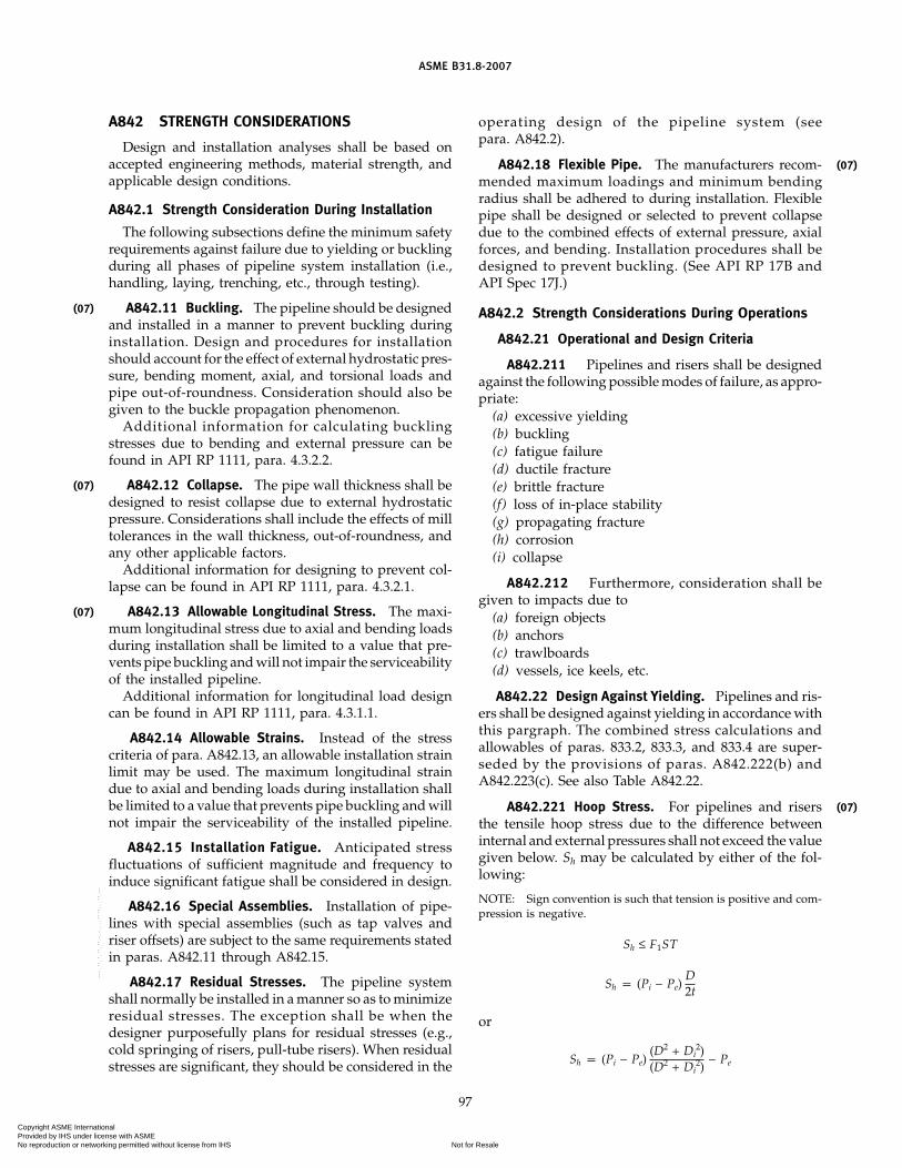
(07)
(07)
(07)
ASME B31.8-2007
A842 STRENGTH CONSIDERATIONS
Design and installation analyses shall be based onaccepted engineering methods, material strength, andapplicable design conditions.
A842.1 Strength Consideration During Installation
The following subsections define the minimum safetyrequirements against failure due to yielding or bucklingduring all phases of pipeline system installation (i.e.,handling, laying, trenching, etc., through testing).
A842.11 Buckling. The pipeline should be designedand installed in a manner to prevent buckling duringinstallation. Design and procedures for installationshould account for the effect of external hydrostatic pres-sure, bending moment, axial, and torsional loads andpipe out-of-roundness. Consideration should also begiven to the buckle propagation phenomenon.
Additional information for calculating bucklingstresses due to bending and external pressure can befound in API RP 1111, para. 4.3.2.2.
A842.12 Collapse. The pipe wall thickness shall bedesigned to resist collapse due to external hydrostaticpressure. Considerations shall include the effects of milltolerances in the wall thickness, out-of-roundness, andany other applicable factors.
Additional information for designing to prevent col-lapse can be found in API RP 1111, para. 4.3.2.1.
A842.13 Allowable Longitudinal Stress. The maxi-mum longitudinal stress due to axial and bending loadsduring installation shall be limited to a value that pre-vents pipe buckling and will not impair the serviceabilityof the installed pipeline.
Additional information for longitudinal load designcan be found in API RP 1111, para. 4.3.1.1.
A842.14 Allowable Strains. Instead of the stresscriteria of para. A842.13, an allowable installation strainlimit may be used. The maximum longitudinal straindue to axial and bending loads during installation shallbe limited to a value that prevents pipe buckling and willnot impair the serviceability of the installed pipeline.
A842.15 Installation Fatigue. Anticipated stressfluctuations of sufficient magnitude and frequency toinduce significant fatigue shall be considered in design.
A842.16 Special Assemblies. Installation of pipe-lines with special assemblies (such as tap valves andriser offsets) are subject to the same requirements statedin paras. A842.11 through A842.15.
A842.17 Residual Stresses. The pipeline systemshall normally be installed in a manner so as to minimizeresidual stresses. The exception shall be when thedesigner purposefully plans for residual stresses (e.g.,cold springing of risers, pull-tube risers). When residualstresses are significant, they should be considered in the
97
operating design of the pipeline system (seepara. A842.2).
A842.18 Flexible Pipe. The manufacturers recom-mended maximum loadings and minimum bendingradius shall be adhered to during installation. Flexiblepipe shall be designed or selected to prevent collapsedue to the combined effects of external pressure, axialforces, and bending. Installation procedures shall bedesigned to prevent buckling. (See API RP 17B andAPI Spec 17J.)
A842.2 Strength Considerations During Operations
A842.21 Operational and Design Criteria
A842.211 Pipelines and risers shall be designedagainst the following possible modes of failure, as appro-priate:
(a) excessive yielding(b) buckling(c) fatigue failure(d) ductile fracture(e) brittle fracture(f) loss of in-place stability(g) propagating fracture(h) corrosion(i) collapse
A842.212 Furthermore, consideration shall begiven to impacts due to
(a) foreign objects(b) anchors(c) trawlboards(d) vessels, ice keels, etc.
A842.22 Design Against Yielding. Pipelines and ris-ers shall be designed against yielding in accordance withthis pargraph. The combined stress calculations andallowables of paras. 833.2, 833.3, and 833.4 are super-seded by the provisions of paras. A842.222(b) andA842.223(c). See also Table A842.22.
A842.221 Hoop Stress. For pipelines and risersthe tensile hoop stress due to the difference betweeninternal and external pressures shall not exceed the valuegiven below. Sh may be calculated by either of the fol-lowing:
NOTE: Sign convention is such that tension is positive and com-pression is negative.
Sh ≤ F1ST
Sh p (Pi − Pe)D2t
or
Sh p (Pi − Pe)(D2 + Di
2)(D2 + Di
2)− Pe
(07)
(07)
Copyright ASME International Provided by IHS under license with ASME
Not for ResaleNo reproduction or networking permitted without license from IHS
--`,,```,,,,````-`-`,,`,,`,`,,`---

(07)
ASME B31.8-2007
Table A842.22 Design Factors for OffshorePipelines, Platform Piping, and Pipeline Risers
F1 F2 F3
Hoop Longitudinal CombinedLocation Stress Stress Stress
Pipeline 0.72 0.80 0.90Platform piping and risers 0.50 0.80 0.90
[Note (1)]
NOTE:(1) The wall thickness used in the calculation of combined stress
for platform piping and risers shall be based upon specifiedminimum wall thickness, including manufacturing, corrosion,and erosion allowances.
whereD p nominal outside diameter of pipe, in.Di p D − 2t, in.F1 p hoop stress design factor from Table A842.22Pe p external pressure, psigPi p internal design pressure, psigS p specified minimum yield strength, psi
Sh p hoop stress, psiT p temperature derating factor from Table
841.116At p nominal wall thickness, in.
A842.222 Longitudinal Stress. For pipelines andrisers the longitudinal stress shall not exceed valuesfound from
�SL � ≤ F2S
whereA p cross-sectional area of pipe material, in.2
Fa p axial force, lbF2 p longitudinal stress design factor from Table
A842.22Mi p in-plane bending moment, in.-lbMo p out-plane bending moment, in.-lb
S p specified minimum yield strength, psiSL p maximum longitudinal stress, psi (positive ten-
sile or negative compressive)p Sa + Sb or Sa − Sb, whichever results in the larger
stress valueSa p axial stress, psi (positive tensile or negative
compressive)p Fa / A
Sb p resultant bending stress, psip [(ii Mi)2 + (io Mo)2] 1/2/z
ii p in-plane stress intensification factor fromAppendix E
io p out-plane stress intensification factor fromAppendix E
z p section modulus of pipe, in.3
� � p absolute value
98
Additional information for longitudinal load designcan be found in API RP 1111, para. 4.3.1.1.
A842.223 Combined Stress. For pipelines and ris-ers the combined stress shall not exceed the value givenby the maximum shear stress equation (Tresca combinedstress):
2 � � SL − Sh
2 � 2+ St
2 � 1/2≤ F3S
whereA p cross-sectional area of pipe material, in.2
Fa p axial force, lbF3 p combined stress design factor from Table
A842.22Mi p in-plane bending moment, in.-lbMo p out-plane bending moment, in.-lbMt p torsional moment, in.-lb
S p specified minimum yield strength, psiSL p maximum longitudinal stress, psi (positive
tensile or negative compressive)p Sa + Sb or Sa − Sb, whichever results in the
larger stress valueSa p axial stress, psi (positive tensile or negative
compressive)p Fa / A
Sb p resultant bending stress, psip [(ii Mi)2 + (io Mo)2] 1/2/z
Sh p hoop stress, psiSt p torsional stress, psi
p Mt/2zii p in-plane stress intensification factor from
Appendix Eio p out-plane stress intensification factor from
Appendix Ez p section modulus of pipe, in.3
Alternatively, the Maximum Distortional EnergyTheory (Von Mises combined stress) may be used forlimiting combined stress values. Accordingly, the com-bined stress should not exceed values given by
(Sh2 − SLSh + SL
2 + 3St2)1/2 ≤ F3S
A842.23 Alternate Design for Strain. In situationswhere the pipeline experiences a predictable noncyclicdisplacement of its support (e.g., fault movement alongthe pipeline route or differential subsidence along theline) or pipe sag before support contact, the longitudinaland combined stress limits need not be used as a crite-rion for safety against excessive yielding, so long asthe consequences of yielding are not detrimental to theintegrity of the pipeline. The permissible maximum lon-gitudinal strain depends on the ductility of the material,any previously experienced plastic strain, and the buck-ling behavior of the pipe. Where plastic strains are antici-pated, the pipe eccentricity, pipe out-of-roundness, andthe ability of the weld to undergo such strains without
(07)
Copyright ASME International Provided by IHS under license with ASME
Not for ResaleNo reproduction or networking permitted without license from IHS
--`,,```,,,,````-`-`,,`,,`,`,,`---

(07)
(07)
ASME B31.8-2007
detrimental effect should be considered. Similarly, thesame criteria may be applied to the pipe during construc-tion (e.g., pull-tube or bending shoe risers).
A842.24 Design Against Buckling and Ovalization.Avoidance of buckling of the pipeline and riser duringoperation shall be considered in design. Modes of buck-ling that may be possible include
(a) local buckling of the pipe wall(b) propagation buckling following local buckling(c) column bucklingAdditional information for determining buckling
tendencies can be found in API RP 1111, paras. 4.3.2.2and 4.3.2.3, and Appendix D.
A842.25 Design Against Fatigue. Stress fluctuationsof sufficient magnitude and frequency to induce signifi-cant fatigue should be considered in design.
Loadings that may affect fatigue include:(a) pipe vibration, such as that induced by vortex
shedding(b) wave actionPipe and riser spans shall be designed so that vortex
induced resonant vibrations are prevented, wheneverpractical. When doing so is impractical, the total resul-tant stresses shall be less than the allowable limits inpara. A842.22, and such that fatigue failure should notresult during the design life of the pipeline.
Additional information for fatigue analysis can befound in API RP 1111, para. 4.5.
A842.26 Design Against Fracture. Materials usedfor pipelines transporting gas or gas-liquid mixturesunder high pressure should have reasonably high resist-ance to propagating fractures at the design conditions,or other methods shall be used to limit the extent of afracture.
A842.27 Design of Clamps and Supports. Clampsand supports shall be designed such that a smooth trans-fer of loads is made from the pipeline or riser to thesupporting structure without highly localized stressesdue to stress concentrations. When members are to bewelded to the pipe they shall fully encircle the pipe andbe welded to the pipe by a full encirclement weld. Thesupport shall be attached to the encircling member andnot the pipe.
All welds to the pipe shall be nondestructively tested.Clamps and supports shall be designed in accordancewith the requirements of API RP 2A, Section 3.
Clamp and support design shall consider the corrosiveeffects of moisture retaining gaps and crevices and gal-vanically dissimilar metals.
A842.28 Design of Connectors and Flanges. Con-nectors and flanges shall be such that smooth transferof loads is made without high localized stresses or exces-sive deformation of the attached pipe.
99
Connectors and flanges shall have a level of safetyagainst failure by yielding and failure by fatigue that iscomparable to that of the attached pipeline or riser.
A842.29 Design of Structural Pipeline Riser Protec-tors. Where pipeline risers are installed in locationssubject to impact from marine traffic, protective devicesshall be installed in the zone subject to damage to protectthe pipe and coating.
A842.30 Design and Protection of Special Assem-blies. Design of connections and special assemblies,such as subsea tie-in assemblies, expansion loops, sea-bed riser connections, and subsea pipeline manifolds,shall consider the additional forces and effects imposedby a subsea environment. Such additional considera-tions include design storm currents and potential forseabed movement in soft sediments, soil liquefaction,increased potential corrosion, thermal expansion andcontraction, and stress due to installation procedures.In areas of active fishing, protective measures may beappropriate for connections and special assemblies.
A842.31 Design of Flexible Pipe. Due to its compos-ite makeup, the mechanical behavior of flexible pipe issignificantly different from steel pipe. Flexible pipe maybe used for offshore pipelines if calculations and/or testresults verify that the pipe can safely withstand loadingsconsidered in paras. A841.32 through A841.33. In theselection of flexible pipe, consideration should be givento its permeable nature. The possibility of implosionunder the combined conditions of high pressure, hightemperature, and very rapid depressurization should beinvestigated where such conditions may be expected.Selection of flexible pipe shall be in accordance withAPI RP 17B and API Spec 17J.
A843 COMPRESSOR STATIONS
A843.1 Compressor Station Design
The requirements of this paragraph recognize theunique design conditions and space limitations imposedwhen designing offshore compression facilities andtherefore relate only to offshore compression facilities.
It is the further intent of this section to make thedesigner aware of personnel safety during the designand operation of offshore compression facilities.
A843.11 Location of Compressor Facilities. Thecompressor facilities located on platforms should bedesigned to facilitate free movement of fire fighting orother emergency equipment.
A843.12 Enclosures. All enclosures located on anoffshore platform shall be constructed of noncombusti-ble or limited combustible material as defined inNFPA 220, Chapter 2, Section 2-6 and Section 2-3. Designof enclosures on offshore platforms shall consider theloading conditions defined in para. A841.3.
(07)
Copyright ASME International Provided by IHS under license with ASME
Not for ResaleNo reproduction or networking permitted without license from IHS
--`,,```,,,,````-`-`,,`,,`,`,,`---

ASME B31.8-2007
A843.13 Exits. A minimum of two exits shall beprovided for each operating level of a compressor build-ing. Any elevated walkway, including engine catwalksmore than 10 ft above the deck, shall also be providedwith two exits. The maximum distance from any pointwithin the compressor building to an exit shall notexceed 75 ft. Enclosure exits shall be unobstructed andlocated so as to provide a convenient route of escapeand shall provide continuous unobstructed passage toa place of safety. Exit doors located on exterior wallsshall swing outward and shall be equipped with latchesthat can be readily opened from the inside without a key.
A843.2 Electrical Facilities
All electrical equipment and wiring installed on off-shore compression platforms shall conform to therequirements of NFPA 70, if commercially availableequipment permits.
Electrical installations in offshore hazardous locationsas defined in NFPA 70, Chapter 5, Article 500 and thatare to remain in operation during compressor stationemergency shutdown as provided in para. A844.431shall be designed to conform to NFPA 70, for Class I,Division I requirements.
The guidelines of API RP 14F should be consideredin electrical facility design.
A843.4 Compressor Station Equipment
A843.43 Safety Devices
A843.431 Emergency Shutdown Facilities. All gascompression equipment shall be provided with an emer-gency shutdown system that will block out the gas goingto and from the compressor station. Operation of theemergency shutdown system shall cause the shutdownof all gas compression equipment and all gas fired equip-ment and shall de-energize the electrical facilities in thecompressor building, except for those that provide emer-gency lighting for personnel protection and those thatare necessary for protection of equipment. The emer-gency shutdown system shall be operable from a mini-mum of two locations on each deck level; that is, shouldan offshore platform facility have more than one clearlydefined deck, each deck shall have a minimum of twoshutdown locations. Blowdown piping shall extend toa location where the discharge of gas is not likely tocreate a hazard to the platform facilities. Considerationshould be given to potential entrained liquids, prevailingwinds, and location of crew quarters if part of the plat-form facility. Under conditions of heavy liquid entrain-ment and poor prevailing wind conditions, a separatestructure for a blowdown facility shall be considered.
A843.44 Pressure-Limiting Requirements for Off-shore Compression Facilities
A843.443 Venting. Pressure relief valves shall bevented to atmosphere such that no hazard is created.
100
Vent lines, common headers, and platform blowdownlines shall have sufficient capacity so that they will notinterfere with the performance of the relief device.
A844 ON-BOTTOM STABILITY
Pipeline design for lateral and vertical stability is gov-erned by seafloor bathymetry, soil characteristics, andby hydrodynamic, seismic, and soil behavior events hav-ing a significant probability of occurrence during thelife of the system. Design conditions to consider areprovided in following subsections.
The pipeline system shall be designed to prevent hori-zontal and vertical movements, or shall be designed sothat any movements will be limited to values not causingdesign strength to be exceeded (see para. A842).
Typical factors to be considered in the stability designinclude
(a) wave and current forces(b) scour and resultant spanning(c) liquefaction(d) slope failureStability may be obtained by such means including,
but not limited to, pipe submerged weight, trenching ofpipe below grade, and anchoring.
When calculating hydrodynamic forces, the spatialvariance of wave forces along the length of the pipelinemay be taken into account.
Additional information on hydrostatic stability canbe found in API RP 1111, para. 4.4.2.
A844.1 Design Storm Conditions
Design wave and current conditions for portions of apipeline that will not be trenched shall be based on astorm having a minimum return interval of no less thanfive times the design life or 100 years, whichever issmaller. Portions of the pipeline system to be trenchedshall be designed for wave and current conditions basedon prudent assessment of the period of pipe exposure.The most unfavorable expected combination of waveand current conditions shall be used. Maximum waveand maximum current conditions do not necessarilyoccur simultaneously. The most unfavorable conditionselection shall account for the timing of occurrence ofthe wave and current direction and magnitude.
A844.2 Stability Against Waves and Currents
A844.21 Submerged Weight. The submergedweight of the pipe may be designed (such as by weightcoating) to resist or limit movement to acceptable values.Hydrodynamic forces shall be based on the wave andcurrent values for the design storm condition for thespecific location.
Wave and current directionality and concurrency shallbe considered.
(07)
Copyright ASME International Provided by IHS under license with ASME
Not for ResaleNo reproduction or networking permitted without license from IHS
--`,,```,,,,````-`-`,,`,,`,`,,`---

ASME B31.8-2007
A844.22 Bottom Soils. The pipe-soil interaction fac-tors that are used shall be representative of the bottomconditions at the site.
A844.23 Trenching. The pipeline and its appurte-nances may be trenched below bottom grade to providestability. The pipeline must be designed for wave andcurrent stability prior to trenching. Such stability, how-ever, need only be based on environmental conditionsexpected during the period of pipe exposure.
A844.24 Backfilling. Backfilling or other protectivecoverings, when necessary, shall be accomplished byusing such materials and procedures to preclude dam-age to the pipeline and coatings.
A844.25 Anchoring. Anchoring may be usedinstead of or in conjunction with submerged weightto maintain stability. The anchors shall be designed towithstand lateral and vertical loads expected from thedesign storm condition. Anchors shall be spaced to pre-vent excessive stresses in the pipe sections betweenanchors. The anchoring system and adjacent pipe shallbe designed to prevent scour and resultant spanningfrom overstressing the pipe. The effect of anchors on thecathodic protection system shall be considered.
A844.3 Shore Approaches
Pipe in the shore approach zone shall be trenchedor bored to the depth necessary to prevent scouring,spanning, or stability problems that affect integrity andsafe operation of the pipeline during its anticipated ser-vice life. Seasonal variation in the near shore thicknessof seafloor sediments and shoreline erosion over thepipeline service life shall be considered.
A844.4 Slope Failure
The pipeline shall be designed for slope failure inzones of known or anticipated occurrence, such as mud-slide zones and areas of seismic slumping. The designexposure period shall be no less than the expected lifeof the pipline. If it is not practical to design the pipelinesystem to survive the event, the pipeline shall bedesigned for controlled breakaway with check valvingto prevent blowdown of the pipeline.
A844.5 Soil Liquefaction
Design for the effects of liquefaction shall be per-formed for areas of known or expected occurrence. Soilliquefaction normally results from cyclic wave overpres-sures or seismic loading of susceptible soils. The bulkspecific gravity of the pipeline shall be designed, oralternative methods shall be selected to ensure bothhorizontal and vertical stability.
Seismic design conditions used to predict the occur-rence of bottom liquefaction or slope failure shall havethe same recurrence interval as used for the operatingdesign strength calculations for the pipeline. Occurrence
101
of soil liquefaction due to wave overpressures shall bebased on a storm return interval of no less than fivetimes the design life or 100 years, whichever is smaller.
A846 VALVES
Offshore transmission lines shall be equipped withvalves or other components to shut off the flow of gasto an offshore platform in an emergency.
Block valves shall be accessible and protected fromdamage and tampering. If a blowdown valve is involved,it shall be located where the gas can be blown to theatmosphere without undue hazard.
Blowdown valves shall be provided so that each sec-tion of pipeline between main line valves can be blowndown. The sizes and capacity of the connections forblowing down the line shall be such that under emer-gency conditions the section of line can be blown downas rapidly as is practicable.
A847 TESTING
A847.1 General Provisions
All offshore pipelines shall be tested after installationand prior to operation within the provisions of thissection.
A847.2 Test Pressure
The installed pipeline system shall be hydrostaticallytested to at least 1.25 times the maximum allowableoperating pressure. Offshore platform piping and off-shore pipeline risers must be tested to at least 1.4 timesthe maximum allowable operating pressure either beforeor after installation. Prefabricated portions of platformpiping that have been pretested to 1.4 times the maxi-mum allowable operating pressure need not be testedafter installation if all items are tied in by connectors,flanges, or welds that have been radiographicallyinspected.
CAUTION: When an external pressure, Pe, greater than zero isused in the hoop stress formula in para. A842.221, there is apossible combination of conditions where the yield strength ofthe pipe could be exceeded during the hydrostatic test. Therefore,the hoop stress shall be checked to see that it is within allowablelimits considering both the internal and external pressures whendetermining the maximum hydrostatic test pressure.
A847.3 Test Medium
The test medium for all offshore pipelines will bewater. Additives to mitigate the effects of corrosion,biofouling, and freezing should be considered. Suchadditives should be suitable for the methods of disposalof the test medium.
In arctic areas where freezing of water is a hazard,the use of air, inert gas, or glycol is allowable. Platformgas and compression piping may be tested with inertgas.
(07)
Copyright ASME International Provided by IHS under license with ASME
Not for ResaleNo reproduction or networking permitted without license from IHS
--`,,```,,,,````-`-`,,`,,`,`,,`---

ASME B31.8-2007
A847.4 Test Procedure
The hydrostatic pressure test shall be conducted inaccordance with a specified procedure that shall, at aminimum, provide for
(a) performance of the test after installation andbefore initial operation of the pipeline system except asprovided in para. A847.2.
(b) the inclusion of prefabricated, pretested portionsof offshore pipeline risers in the pipeline system hydro-static test, whenever practical.
(c) maintenance of the test and recording of resultson pipeline and assemblies for a minimum of eight con-tinuous hours at or above the specified pressure. Allvariations in test pressure shall be accounted for. Testduration of prefabricated piping may be 2 hr.
(d) a retest if, during the hold time, a rupture or haz-ardous leak occurs that renders the test invalid. Retestingshall commence after repairs have been made.
A847.5 Records
The operating company shall maintain in its file, forthe useful life of each pipeline, records showing the typeof test fluid, the test procedure, the test pressure, andthe duration of the test.
A847.6 Tie-ins
It is recognized that it may not be possible to hydro-statically test the tie-in between two test sections. Pres-sure testing of tie-in welds may be exempted if the tie-in weld is inspected by radiographic and/or other appli-cable NDT methods.
A847.7 Testing for Buckles
Testing for buckles, dents, and other diameter restric-tions shall be performed after installation. Testing shallbe accomplished by passing a deformation detectiondevice through the pipeline section, or by other methodscapable of detecting a change in pipe diameter. Pipehaving excessive deformation which affects the service-ability of the pipeline facilities shall be repaired orreplaced. Consideration should also be given torepairing excessive ovality which may interfere withpigging operation or internal inspection.
A850 OPERATING AND MAINTENANCEPROCEDURES AFFECTING THE SAFETY OFGAS TRANSMISSION FACILITIES
A850.1 General
All provisions of Chapter V, which depend on locationclass, do not apply to offshore gas transmission systems,except that offshore pipelines approaching shorelineareas shall additionally be operated and maintained con-sistently with Class Location provisions as determinedin para. 840.
102
A850.3 Essential Features of the Operating andMaintenance Plan
The plan prescribed in para. 850.2(a) shall include(a) detailed plans and instructions for employees cov-
ering operating and maintenance procedures for gasfacilities during normal operations and repairs
(b) items recommended for inclusion in the plan forspecific classes of facilities, which are given in paras.A851.2, A851.4, and A860
(c) plans to give particular attention to those portionsof the facilities presenting the greatest hazard to thepublic and environment in the event of an emergencyor because of construction or extraordinary maintenancerequirements
(d) provisions for periodic inspections along the routeof existing pipelines
A850.4 Essential Features of the Emergency Plan
A850.43 Liaison. Each operating company shallestablish and maintain liaison with available offshorefire fighting entities (public and or privately owned)that might be designated for any particular offshore area.
A850.44 Educational Program. An educational pro-gram shall be established to enable producers and thegeneral public operating in the offshore area to recognizeand report a gas emergency to the appropriate officials.The educational program called for under this sectionshould be tailored to the type of pipeline operation andthe environment traversed by the pipeline and shouldbe conducted in each language that is significant in thecommunity served. Operators of transmission systemsshould communicate their programs to people, contrac-tors, or others that usually work in the offshore area ofconcern. The programs of operators in the same areashould be coordinated to properly direct reports of emer-gencies and to avoid inconsistencies.
A850.7 Blasting Effects
Each operating company shall establish proceduresfor protection of facilities in the vicinity of blasting activ-ities. The operating company shall
(a) locate and mark its pipeline when explosives areto be detonated within distances as specified in companyplans. Consideration should be given to the marking ofminimum blasting distances from the pipelinesdepending on the type of blasting operation.
(b) determine the necessity and extent of observingor monitoring blasting activities based on the proximityof the blast considering the pipe materials, the operatingconditions, the size of charge, and soil conditions.
Consideration should be given to(1) the effect of shock waves on the pipeline from
blasting(2) conducting a leak survey following completion
of the blasting program
Copyright ASME International Provided by IHS under license with ASME
Not for ResaleNo reproduction or networking permitted without license from IHS
--`,,```,,,,````-`-`,,`,,`,`,,`---
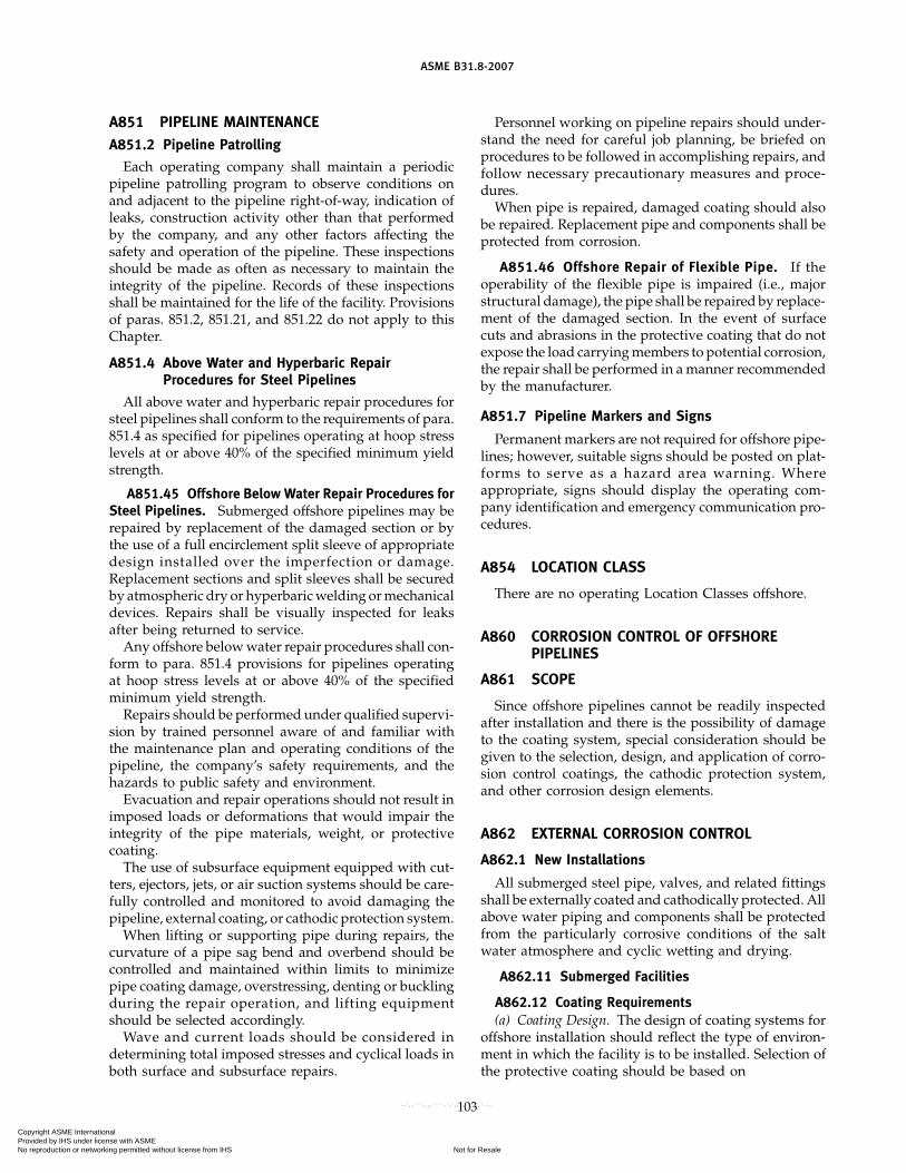
ASME B31.8-2007
A851 PIPELINE MAINTENANCEA851.2 Pipeline Patrolling
Each operating company shall maintain a periodicpipeline patrolling program to observe conditions onand adjacent to the pipeline right-of-way, indication ofleaks, construction activity other than that performedby the company, and any other factors affecting thesafety and operation of the pipeline. These inspectionsshould be made as often as necessary to maintain theintegrity of the pipeline. Records of these inspectionsshall be maintained for the life of the facility. Provisionsof paras. 851.2, 851.21, and 851.22 do not apply to thisChapter.
A851.4 Above Water and Hyperbaric RepairProcedures for Steel Pipelines
All above water and hyperbaric repair procedures forsteel pipelines shall conform to the requirements of para.851.4 as specified for pipelines operating at hoop stresslevels at or above 40% of the specified minimum yieldstrength.
A851.45 Offshore Below Water Repair Procedures forSteel Pipelines. Submerged offshore pipelines may berepaired by replacement of the damaged section or bythe use of a full encirclement split sleeve of appropriatedesign installed over the imperfection or damage.Replacement sections and split sleeves shall be securedby atmospheric dry or hyperbaric welding or mechanicaldevices. Repairs shall be visually inspected for leaksafter being returned to service.
Any offshore below water repair procedures shall con-form to para. 851.4 provisions for pipelines operatingat hoop stress levels at or above 40% of the specifiedminimum yield strength.
Repairs should be performed under qualified supervi-sion by trained personnel aware of and familiar withthe maintenance plan and operating conditions of thepipeline, the company’s safety requirements, and thehazards to public safety and environment.
Evacuation and repair operations should not result inimposed loads or deformations that would impair theintegrity of the pipe materials, weight, or protectivecoating.
The use of subsurface equipment equipped with cut-ters, ejectors, jets, or air suction systems should be care-fully controlled and monitored to avoid damaging thepipeline, external coating, or cathodic protection system.
When lifting or supporting pipe during repairs, thecurvature of a pipe sag bend and overbend should becontrolled and maintained within limits to minimizepipe coating damage, overstressing, denting or bucklingduring the repair operation, and lifting equipmentshould be selected accordingly.
Wave and current loads should be considered indetermining total imposed stresses and cyclical loads inboth surface and subsurface repairs.
103
Personnel working on pipeline repairs should under-stand the need for careful job planning, be briefed onprocedures to be followed in accomplishing repairs, andfollow necessary precautionary measures and proce-dures.
When pipe is repaired, damaged coating should alsobe repaired. Replacement pipe and components shall beprotected from corrosion.
A851.46 Offshore Repair of Flexible Pipe. If theoperability of the flexible pipe is impaired (i.e., majorstructural damage), the pipe shall be repaired by replace-ment of the damaged section. In the event of surfacecuts and abrasions in the protective coating that do notexpose the load carrying members to potential corrosion,the repair shall be performed in a manner recommendedby the manufacturer.
A851.7 Pipeline Markers and Signs
Permanent markers are not required for offshore pipe-lines; however, suitable signs should be posted on plat-forms to serve as a hazard area warning. Whereappropriate, signs should display the operating com-pany identification and emergency communication pro-cedures.
A854 LOCATION CLASS
There are no operating Location Classes offshore.
A860 CORROSION CONTROL OF OFFSHOREPIPELINES
A861 SCOPE
Since offshore pipelines cannot be readily inspectedafter installation and there is the possibility of damageto the coating system, special consideration should begiven to the selection, design, and application of corro-sion control coatings, the cathodic protection system,and other corrosion design elements.
A862 EXTERNAL CORROSION CONTROL
A862.1 New Installations
All submerged steel pipe, valves, and related fittingsshall be externally coated and cathodically protected. Allabove water piping and components shall be protectedfrom the particularly corrosive conditions of the saltwater atmosphere and cyclic wetting and drying.
A862.11 Submerged Facilities
A862.12 Coating Requirements(a) Coating Design. The design of coating systems for
offshore installation should reflect the type of environ-ment in which the facility is to be installed. Selection ofthe protective coating should be based on
Copyright ASME International Provided by IHS under license with ASME
Not for ResaleNo reproduction or networking permitted without license from IHS
--`,,```,,,,````-`-`,,`,,`,`,,`---

ASME B31.8-2007
(1) low water absorption(2) compatibility with the type of cathodic protec-
tion to be applied to the system(3) compatibility with the system operating tem-
perature(4) sufficient ductility to minimize detrimental
cracking(5) sufficient toughness to withstand damage dur-
ing installation(6) resistance to future deterioration in a sub-
merged environment(7) ease of repair
(b) Cleaning and Surface Preparation. There may beadditional cleaning and surface preparation require-ments, such as a near white metal finish and an anchorpattern to promote a good bond for all epoxy-based thinfilm coatings. Welds should be inspected for irregulari-ties that could protrude through the pipe coating, andany such irregularities should be removed.
(c) Application and Inspection. The coating should beapplied under controlled conditions and have a highresistance to disbondment. Further information can beobtained from NACE RP-06-75, Section 4. A holidaydetector, suitable for the type of coating applied, shallbe used to detect flaws. Flaws noted shall be repairedand retested. Weights or weight coating shall not dam-age the protective coating during application or instal-lation.
(d) Coating for Weld Joints, Appurtenances, and Patching.Weld joints and appurtenances shall be coated withmaterial that is compatible with the basic coating. Aholiday detector, designed for the type of field jointmaterial applied, may be used to detect flaws, and flawsshall be repaired and retested.
(e) Field Inspection. The pipe shall be visuallyinspected prior to installation to ensure that unaccept-able damage has not occurred during loading, welding,or other laying activities prior to submergence of thepipe. Any significant damage to the coating shall berepaired with material compatible with the pipelinecoating. Care should be exercised to minimize damageto the coating system, particularly during laying andtrenching of the pipe.
A862.13 Cathodic Protection Requirements(a) Design Criteria. An offshore facility is considered
to be cathodically protected when it meets one or moreof the criteria established in Appendix K.
(b) Impressed Currents. Where impressed current sys-tems are used, the system shall be designed to minimizeoutages, and the output shall be such that the designcriterion is met. Also, consideration should be given tominimize the interference effect on other pipelines orstructures.
(c) Galvanic Anodes. Where galvanic anodes are usedfor protection, consideration shall be given to the qualityof the coating (i.e., the percent of exposed pipe). Also,
104
the design formula for the system should include theoutput of the anodes, the desired life of the system,anode material, and utilization efficiency. Anodes usedshould be compatible with the operating temperatureof the pipeline and the marine environment.
(d) Other. Consideration should be given to theeffects on cathodic protection of variations in oxygencontent, temperature, and water/soil resistivity of theparticular offshore environment in which the pipelineis installed.
A862.14 Electrical Isolation. Underwater pipelinesystems shall be electrically isolated from other metallicstructures so that cathodic protection can be effective.An exception can be made when both the foreign struc-ture and the pipeline are designed to be protected as aunit. Other general considerations include the following:
(a) Tie-Ins. Isolation from foreign pipelines at tie-insmay be made by installing insulation flanges, unions,or other insulating devices. When making a tie-in of acoated line to a bare line, the two lines shall be electri-cally isolated.
(b) Foreign Pipeline Crossings. When crossing a foreignpipeline, care shall be exercised to ensure adequate sepa-ration between the two lines so that the possibility forelectrical interference is minimized.
(c) Pipeline Riser Support and Secondary Piping. Wheninstalling riser piping at platforms, supporting devicessuch as clamps and pipe supports shall isolate the pipingfrom the structure. Insulating devices shall be installedwhere electrical isolation of a portion of the piping sys-tem from production piping, tanks, and other facilities isnecessary to facilitate application of cathodic protection.Electrical interference between electrically isolatedstructures shall be minimized. Wiring and piping con-nections to an isolated pipeline shall also have insulationbetween the pipeline and the platform. Tests shall bemade to ensure adequate isolation, and appropriateaction shall be taken to ensure such isolation when nec-essary.
A862.15 Electrical Connections and MonitoringPoints. Test leads shall be installed so that they aremechanically secure, electrically conductive, and acces-sible for testing. It is considered impractical to locatetest leads in deep or open water. Test leads installationsare usually limited to platforms and the pipelineentrance to the shore.
A862.16 Atmospheric Protection(a) The splash zone area, where the pipeline is inter-
mittently wet and dry, shall be designed with additionalprotection against corrosion. This shall be accomplishedby one or more of the following:
(1) special coating(2) special protective systems and techniques(3) other suitable measures, including selection of
pipe material
Copyright ASME International Provided by IHS under license with ASME
Not for ResaleNo reproduction or networking permitted without license from IHS
--`,,```,,,,````-`-`,,`,,`,`,,`---

ASME B31.8-2007
(b) Coatings and other protective systems shall beinstalled on a properly prepared surface and in accor-dance with established specifications or manufacturer’srecommendations. The coating should resist wateraction, atmospheric deterioration, mechanical damage,and cathodic disbondment.
A862.2 Existing Installations
The operating company must rely on monitoring,investigation, inspections, and corrective action to con-trol corrosion. Such activities shall be performed at peri-odic intervals sufficient to ensure that adequatecorrosion control is maintained. Where it is determinedthat corrosion that is taking place may be detrimentalto public or employee safety, the facility shall be repairedor replaced, and corrosion control measures shall beapplied or augmented.
A862.21 Submerged Facilities
A862.214 Cathodic Protection Criteria(a) Criteria. The criteria for cathodic protection are
specified in Appendix K.(b) Electrical Checks. The operating company shall
take electrical readings periodically at each test locationavailable to ensure that the cathodic protection levelmeets one of the criteria in Appendix K.
Before each electrical test is performed, an inspectionshall be made to ensure electrical continuity and that agood contact to the pipelines is made by the test con-nection.
A862.215 Electrical Interference. Periodic testsshall be made to ensure that electrical isolation fromforeign pipelines or other structures remains complete.Some indications of electrical interference are changesin pipe to electrolyte potential, changes in current mag-nitude or direction, localized pitting, and coating break-down. When new foreign pipelines are laid in thevicinity of existing lines, inspections shall be made to
105
ensure electrical isolation in accordance with para.862.114. If electrical isolation cannot be attained, mea-sures shall be taken to minimize electrical interference.Electrical isolation from the platform should be checkedand maintained unless the system was specificallydesigned to be jointly protected.
A862.216 Examination When Exposed. When apipeline is lifted above water for maintenance or repair,the operating company shall visually inspect for evi-dence of coating deterioration, external corrosion, andwhere possible, the condition of any exposed anode. Ifexcessive corrosion is present, remedial action shall betaken as necessary.
If repairs are made below water, inspection for evi-dence of external corrosion or coating deterioration shallbe made, and necessary corrective action shall be takento maintain the corrosion protection of the pipeline.
A862.25 Atmospheric Corrosion. Detailed inspec-tions shall be made periodically of all piping for atmo-spheric corrosion. This inspection shall include thoseareas most susceptible to corrosion such as flanges,flange bolts, areas under pipe straps, areas where pipeis in contact with supports, and other places where mois-ture collects. Where atmospheric corrosion is found,prompt corrective action shall be taken. Correctiveaction shall consist of painting, replacement of compo-nents as necessary, or other action deemed appropriateby the operating company.
A863 INTERNAL CORROSION CONTROL
A863.1 General
The design and maintenance of offshore pipeline facil-ities that may carry natural gas containing carbon diox-ide, chlorides, hydrogen sulfide, organic acids, solids orprecipitates, sulfur-bearing compounds, oxygen, or freewater require special consideration for the control ofinternal corrosion.
Copyright ASME International Provided by IHS under license with ASME
Not for ResaleNo reproduction or networking permitted without license from IHS
--`,,```,,,,````-`-`,,`,,`,`,,`---
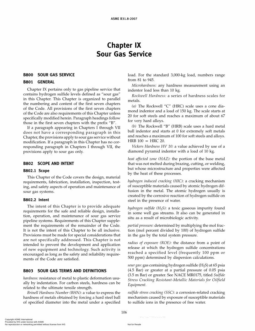
ASME B31.8-2007
Chapter IXSour Gas Service
B800 SOUR GAS SERVICE
B801 GENERAL
Chapter IX pertains only to gas pipeline service thatcontains hydrogen sulfide levels defined as “sour gas”in this Chapter. This Chapter is organized to parallelthe numbering and content of the first seven chaptersof the Code. All provisions of the first seven chaptersof the Code are also requirements of this Chapter unlessspecifically modified herein. Paragraph headings followthose in the first seven chapters with the prefix “B”.
If a paragraph appearing in Chapters I through VIIdoes not have a corresponding paragraph in thisChapter, the provisions apply to sour gas service withoutmodification. If a paragraph in this Chapter has no cor-responding paragraph in Chapters I through VII, theprovisions apply to sour gas only.
B802 SCOPE AND INTENT
B802.1 Scope
This Chapter of the Code covers the design, materialrequirements, fabrication, installation, inspection, test-ing, and safety aspects of operation and maintenance ofsour gas systems.
B802.2 Intent
The intent of this Chapter is to provide adequaterequirements for the safe and reliable design, installa-tion, operation, and maintenance of sour gas servicepipeline systems. Requirements of this Chapter supple-ment the requirements of the remainder of the Code.It is not the intent of this Chapter to be all inclusive.Provisions must be made for special considerations thatare not specifically addressed. This Chapter is notintended to prevent the development and applicationof new equipment and technology. Such activity isencouraged as long as the safety and reliability require-ments of the Code are satisfied.
B803 SOUR GAS TERMS AND DEFINITIONS
hardness: resistance of metal to plastic deformation usu-ally by indentation. For carbon steels, hardness can berelated to the ultimate tensile strength.
Brinell Hardness Number (BHN): a value to express thehardness of metals obtained by forcing a hard steel ballof specified diameter into the metal under a specified
106
load. For the standard 3,000-kg load, numbers rangefrom 81 to 945.
Microhardness: any hardness measurement using anindentor load less than 10 kg.
Rockwell Hardness: a series of hardness scales formetals.
(a) The Rockwell “C” (HRC) scale uses a cone dia-mond indentor and a load of 150 kg. The scale starts at20 for soft steels and reaches a maximum of about 67for very hard alloys.
(b) The Rockwell “B” (HRB) scale uses a hard metalball indentor and starts at 0 for extremely soft metalsand reaches a maximum of 100 for soft steels and alloys.HRB 100 p HRC 20.
Vickers Hardness HV 10: a value achieved by use of adiamond pyramid indentor with a load of 10 kg.
heat affected zone (HAZ): the portion of the base metalthat was not melted during brazing, cutting, or welding,but whose microstructure and properties were affectedby the heat of these processes.
hydrogen induced cracking (HIC): a cracking mechanismof susceptible materials caused by atomic hydrogen dif-fusion in the metal. The atomic hydrogen usually iscreated by the corrosive reaction of hydrogen sulfide onsteel in the presence of water.
hydrogen sulfide (H2S): a toxic gaseous impurity foundin some well gas streams. It also can be generated insitu as a result of microbiologic activity.
partial pressure: determined by multiplying the mol frac-tion (mol percent divided by 100) of hydrogen sulfidein the gas by the total system pressure.
radius of exposure (ROE): the distance from a point ofrelease at which the hydrogen sulfide concentrationsreached a specified level (frequently 100 ppm or500 ppm) determined by dispersion calculations.
sour gas: gas containing hydrogen sulfide (H2S) at 65 psia(4.5 Bar) or greater at a partial pressure of 0.05 psia(3.5 m Bar) or greater. See NACE MR0175, titled SulfideStress Cracking Resistant-Metallic Materials for OilfieldEquipment.
sulfide stress cracking (SSC): a corrosion-related crackingmechanism caused by exposure of susceptible materialsto sulfide ions in the presence of free water.
Copyright ASME International Provided by IHS under license with ASME
Not for ResaleNo reproduction or networking permitted without license from IHS
--`,,```,,,,````-`-`,,`,,`,`,,`---

ASME B31.8-2007
B813 MARKING
Valves meeting NACE MR0175 shall be so identifiedwith a permanent tag or marking.
B814 MATERIAL SPECIFICATIONS
B814.1 General Requirements
Materials must meet the requirements of NACEMR0175.
B820 WELDING SOUR GAS PIPELINES
B821 GENERAL
B821.1
This section concerns the welding of pipe in sour gasservice in both wrought and cast steel materials andcovers butt and fillet welded joints in pipe, valves,flanges, fittings, and fillet welded joints in pipe, slip-onflanges, socket welds, fittings, etc. as applied in pipe-lines, components, and connections to apparatus orequipment.
B821.2 Seam Welds
This section does not apply to the welding of the seamin the manufacture of pipe, but the user is cautioned toensure that such seams are suitable for sour gas servicein their installed condition.
B821.4
The standards of acceptability for welds of pipingsystems as established in API 1104, Section 6, or ASMEBoiler and Pressure Vessel Code, Section VIII, Division1, shall be used; however, additional requirements forhardness and residual stress should be considered.
B822 PREPARATION FOR WELDING
B822.3 Seal Welds
Seal welds shall have a separate qualified procedure.
B822.4 Cleaning
Pipe that has been in sour gas service shall be thor-oughly cleaned to bright metal on the inside surfacesback 1 in. from the weld bevel.
B823 QUALIFICATIONS OF PROCEDURES ANDWELDERS
The requirements of paras. 823.1 and 823.11 shall notapply to this section.
B823.2 Requirements for Qualifications ofProcedures and Welders on Piping Systems
B823.22 All procedure and performance qualifica-tions shall be based on destructive mechanical testrequirements.
107
B823.24 Hardness Control. The hardness of all weldzones including weld metal and heat affected zones onwelding qualification test specimens shall meet the hard-ness requirements for the alloys welded as specifiedin NACE MR0175. For most common pipe alloys, themaximum allowable hardness is HRC 22. It is the user’sresponsibility to ensure the welding qualification speci-men is metallurgically representative of full-scale pipe-line welds.NOTE: Both macrohardness and microhardness surveys of prop-erly prepared qualification specimens are frequently used to deter-mine the presence of thin HAZ hard zones. A commonly acceptedmaximum macrohardness limit near the inside surface is 250 HV10.
B824 PREHEATING
B824.5 Hydrogen Bake Out of Used Pipe
Pipe that has been used in sour gas service shall beheated for at least 20 min at 400°F (204°C) or higher todrive off any hydrogen in the metal. Heating shall bedone just prior to welding. This heating should be inaddition to and immediately preceding any preheatingspecified in the welding procedure for new pipe.
B825 STRESS RELIEVING
B825.2
The chemistry of the steel and welding procedure shallbe controlled to limit the hardness of the weldment asrequired by para. B823.24. When the effectiveness ofsuch controls is questionable, consideration shall begiven to stress relieving welds in sour gas service. Ingeneral, temper bead welding, peening procedures, orlow-temperature postweld heat treatment does not pro-vide the equivalent protection from service cracking asdoes a full thermal stress relief.
B825.6 Stress Relieving Temperature
(a) Stress relieving is normally performed at a temper-ature of 1,100°F (593°C) for carbon steels and 1,200°F(649°C) for ferritic alloy steels. Other stress relievingprocedures may be substituted when properly sup-ported with metallurgical evidence. The exact tempera-ture range shall be stated in the procedure specification.
(b) When stress relieving a joint between dissimilarmetals having different stress relieving requirements,the material requiring the higher stress relieving temper-ature shall govern. Special considerations may berequired for austenitic and other high alloys.
(c) The parts heated shall be brought slowly to therequired temperature and held at that temperature fora period of time proportioned on the basis of at least1 hr/in. (1 hr/25 mm) of pipe wall thickness, but in nocase less than 1⁄2 hr, and shall be allowed to cool slowlyand uniformly.
(d) Records. A suitable record of the stress relief cyclesshall be provided for each weld stress relieved.
Copyright ASME International Provided by IHS under license with ASME
Not for ResaleNo reproduction or networking permitted without license from IHS
--`,,```,,,,````-`-`,,`,,`,`,,`---

ASME B31.8-2007
(e) Temperature Control. A group of closely spacedwelds, such as three welds on a tee, can be controlledand recorded by a single thermocouple.
B826 WELDING AND INSPECTION TESTS
B826.2 Inspection and Tests for Quality Control ofWelds on Sour Gas Piping Systems
In addition to subparas. 826.2(a) through (f), for sourgas lines in Class 3 or 4 Locations, compressor stations,major or navigable river crossings, railroad crossings,and road crossings, 100% of all field welds shall bechecked by nondestructive inspection. Nondestructiveinspection may be conducted before or after stressrelieving.
B830 PIPING SYSTEM COMPONENTS ANDFABRICATION DETAILS
In addition to para. 830, all components shall meetthe requirements of NACE MR0175 as appropriate.
B831 PIPING SYSTEM COMPONENTS
B831.1 Valves and Pressure-Reducing Devices
B831.13(a) Instruments, instrument tubing, controllers,
gauges, and other components that become a part of thepressure containment system shall meet NACE MR0175requirements.
(b) Most copper-based alloys suffer severe corrosionin sour service. Use of such alloys in any componentsshall be investigated for suitability.
B831.2 Flanges
B831.22 Bolting(h) Bolting exposed to sour gas and denied access to
air due to thermal insulation, flange protectors, or cer-tain design features shall meet the requirements ofNACE MR0175 as appropriate. Designers should notethat bolting meeting NACE MR0175 requirements, suchas type ASTM A 193 grade B7M, have derated tensileproperties, and the joint design shall be appropriate forsuch deration. Bolting opened to atmosphere may beconventional ASTM A 193 grade B7 bolting.
B840 DESIGN, INSTALLATION, AND TESTING
B841 STEEL PIPE
B841.1 Steel Piping Systems Design Requirements
B841.11 Steel Pipe Design Formula(c) Fracture Control. Fracture control should be con-
sidered for sour gas service.
108
B841.114 Design Factors F and Location Classes.When using Table 841.114A, design factor F of 0.80 shallnot be used for sour gas service.
B841.2 Installation of Steel Pipelines and Mains
B841.23 Bends, Elbows, and Miters in Steel Pipe-lines
B841.231(f) Bends used in sour gas pipe shall meet the require-
ments of NACE MR0175 in the as-bent condition. Hotbends may be needed to meet NACE MR0175 require-ments. The first prototype bend may be needed for test-ing to ensure hardness requirements of NACE MR0175and that both toughness and tensile properties are stillacceptable. Neither wrinkle bends nor miter bends arepermitted for sour gas lines.
B841.24 Pipe Surfaces Requirements Applicable toPipelines and Mains to Operate at a Hoop Stress of 20%or More of the Specified Minimum Yield Strength
B841.245 Arc Burns. Additionally, arc burns havebeen found to cause serious stress concentration in pipe-lines and in sour gas lines, and shall be prevented oreliminated in all lines.
Arc burns may be removed by grinding, chipping,or machining. The resulting cavity shall be thoroughlycleaned and checked for complete removal of damagedmaterial by etching with a 10% solution of ammoniumpersulfate or a 5% solution of nitric acid in alcohol (nital).If removal of damaged material is complete, the cavitymay be merged smoothly into the original contour ofthe pipe by grinding, provided the remaining wall thick-ness is within specified limits.
B841.26 Hot Taps. In addition to para. 841.26 ofChapter IV, it should be noted that hot tapping of sourgas lines presents special health and metallurgical con-cerns and shall be done only to written operating com-pany approved plans.
B841.27 Precautions to Avoid Explosions of Gas–Air Mixtures or Uncontrolled Fires During ConstructionOperations
B841.271 In addition to the precautions outlinedin para. 841.271 of Chapter IV, it should be noted thatwelding and cutting on sour gas lines presents specialhealth and metallurgical concerns and shall be doneonly to written operating company approved plans.
B841.3 Testing After Construction
B841.31 General Provisions. In addition to para.841.31 of Chapter IV, it should be noted that testingwith sour gas presents special health and metallurgicalconcerns and shall be done only to written operatingcompany approved plans.
Copyright ASME International Provided by IHS under license with ASME
Not for ResaleNo reproduction or networking permitted without license from IHS
--`,,```,,,,````-`-`,,`,,`,`,,`---

ASME B31.8-2007
B842 OTHER MATERIALS
B842.1
Materials shall meet the requirements ofNACE MR0175 as applicable.
B842.3 Design of Plastic Piping
B842.39 Plastic Pipe and Tubing Joints and Connec-tions
B842.392 Joint Requirements. Fusion bondedjoints in thermoplastic pipe used in sour gas service areacceptable. All cement, adhesive, and fusion bondingjoining procedures and joiners shall be qualified to writ-ten procedures using destructive test specimens offull-scale plastic pipe joints.
B843 COMPRESSOR STATIONS
B843.4 Compressor Station Equipment
B843.41 Gas Treating Facilities
B843.413 All metallic materials in contact withpressurized sour gas shall meet the requirements ofNACE MR0175 as applicable.
Personal safety equipment should be considered foruse at sour gas facilities. Use of appropriate hydrogensulfide sensors capable of actuating station emergencyshutdown systems should be considered.
B844 PIPE-TYPE AND BOTTLE-TYPE HOLDERS
Pipe- and bottle-type holders shall not be used forsour gas. Storage of sour gas is outside the scope of thisCode.
B850 ADDITIONAL OPERATING ANDMAINTENANCE CONSIDERATIONS AFFECTINGTHE SAFETY OF SOUR GAS PIPELINES
B850.1
(c) Radius of exposure (ROE) to H2S calculations shallbe made using a suitable air dispersion equation suchas the Pasquel–Gifford equation given as follows:
(1) Each operator shall determine the hydrogen sul-fide concentration in the gaseous mixture in the system.Suitable standards are ASTM D 2385, GPA C-1, GPApublication 2265.
(2) Radius of Exposure Equations(a) Radius of exposure equation to the 100-ppm
level of H2S after dispersal:
X p [(1.589) M Q] 0.6258
(b) Radius of exposure equation to the 500-ppmlevel of H2S after dispersal:
X p [(0.4546) M Q] 0.6258
109
whereM p mol fraction of hydrogen sulfide in the gaseous
mixtureQ p maximum volume determined to be available
for escape in cubic feet per day corrected to14.65 psia and 60°F
X p radius of exposure (ROE) in feet
(3) Metric Equations(a) 100-ppm level of H2S after dispersal:
Xm p[(8.404) M Qm] 0.6258
(b) 500-ppm level of H2S after dispersal:
Xm p [(2.404) M Q] 0.6258
whereM p mol fraction of hydrogen sulfide in the gaseous
mixtureQm p maximum volume determined to be available
for escape in cubic meters per day corrected to1.01 bars and 15.6°C.
Xm p radius of exposure (ROE) in meters
NOTE: The equations assume a 24-hr release. When a pipelinesegment can be isolated in less than 24 hr, appropriate reductionsin Q may be used.
(4) Examples of 100-ppm and 500-ppm ROE forvarious 24-hr releases and H2S mol fractions are asfollows.
100-ppm ROE
ROE Release H2Sft, MMSCFD MolX Q(1,000,000) Fraction
1,165 1 0.053,191 5 0.054,924 10 0.057,597 20 0.059,792 30 0.051,798 1 0.14,924 5 0.17,597 10 0.1
11,723 20 0.115,109 30 0.1
2,775 1 0.27,597 5 0.2
11,723 10 0.218,090 20 0.223,315 30 0.2
Copyright ASME International Provided by IHS under license with ASME
Not for ResaleNo reproduction or networking permitted without license from IHS
--`,,```,,,,````-`-`,,`,,`,`,,`---

ASME B31.8-2007
500-ppm ROE
ROE Release H2Sft, MMSCFD MolX Q(1,000,000) Fraction
533 1 0.051,458 5 0.052,250 10 0.053,472 20 0.054,474 30 0.05
822 1 0.12,250 5 0.13,472 10 0.15,357 20 0.16,904 30 0.11,268 1 0.23,472 5 0.25,357 10 0.28,266 20 0.2
10,654 30 0.2
B850.4 Essential Features of the Emergency Plan
B850.42 Training Program. In addition to conven-tional training, all sour gas operation and maintenanceline personnel shall be trained in
(a) hazards and characteristics of H2S(b) effect on metal components of the lines and
equipment(c) safety precautions(d) operation of safety equipment and life support
systems(e) corrective action and shutdown procedures
B851 PIPELINE MAINTENANCE
B851.7
(d) In addition to each sign required in subpara.851.7(c) of Chapter V, for operations where the 100-ppmradius of exposure is greater than 50 ft (15.2 m), a“POISON GAS” sign shall be installed.
All surface facilit ies shall also be marked with“POISON GAS” signs.
B851.10
When blowing down sour gas lines, considerationshall be given to the use of suitable permanent or tempo-rary flare systems.
B855 CONCENTRATIONS OF PEOPLE IN LOCATIONCLASSES 1 AND 2
B855.1
(c) Security. Unattended fixed surface facilitiesshould be protected from public access when locatedwithin 1⁄4 mile of a residential, commercial, or otherinhabited or occupied structure; bus stop; public park;or similarly populated area.
110
(1) The protection should be provided by fencingand locking or removal of valves and instrumentationand plugging of ports, or other similar means.
(2) Surface pipeline is not considered a fixed sur-face facility.
(d) Additional control and safety procedures or safetydevices should be installed and maintained to preventthe undetected continuing release of hydrogen sulfideif any of the following conditions exist:
(1) The 100-ppm radius of exposure is in excess of50 ft (15.2 m) and includes any part of a public areaexcept a public road.
(2) The 500-ppm radius of exposure is greater than50 ft (15.2 m) and includes any part of a public road.
(3) The 100-ppm radius of exposure is greater than3,000 ft (915 m).
(e) Contingency Plan. Operations subject to (d) aboveshall have a written contingency plan prepared andgiven to state and local emergency response authorities.Plans shall include maps, location of block valves, valvekeys, and keys for locks.
B860 CORROSION CONTROL OF SOUR GASPIPELINES
B861 GENERAL
B861.1 Scope
This section contains the minimum additive or substi-tutive requirements for corrosion control of external andinternal corrosion of sour gas piping and components.Where specific provisions are not set forth herein, theprovisions of para. 860 of Chapter VI shall apply.
B861.2 Special Considerations
Due to the corrosivity of hydrogen sulfide and thefrequent presence of carbon dioxide and salt water,which also are corrosive, special emphasis shall be givento internal corrosion mitigation and monitoring.
Also, due to the corrosive and hazardous nature ofthe sour gas, special consideration shall be given to theselection of the corrosion allowance.
B862 EXTERNAL CORROSION CONTROL
B862.1 New Installations
B862.11 Buried Steel Facilities
B862.113 Cathodic Protection Requirements.Unless it can be demonstrated by tests or experiencethat cathodic protection is not needed, all buried orsubmerged facilities with insulating type coatings,except facilities installed for a limited service life, shallbe cathodically protected as soon as feasible followinginstallation, except that minor replacements or exten-sions shall be protected as covered by para. 862.212.
Copyright ASME International Provided by IHS under license with ASME
Not for ResaleNo reproduction or networking permitted without license from IHS
--`,,```,,,,````-`-`,,`,,`,`,,`---

ASME B31.8-2007
Facilities installed for a limited service life need notbe cathodically protected if it can be demonstrated thatthe facility will not experience corrosion that will causeit to be harmful to the public or environment. Cathodicprotection systems shall be designed to protect the bur-ied or submerged system in its entirety.
A facility is considered to be cathodically protectedwhen it meets one or more of the criteria established inAppendix K.
Use of cathodic protection is encouraged to protectburied sour gas facilities.
B863 INTERNAL CORROSION CONTROLB863.1 General
Sour gas facilities shall be assumed to be internallycorrosive unless proven by experience to be otherwise.Water dewpoint control frequently is used as a corrosioncontrol method. Upset conditions or operational changesmay make this control method ineffective. The use ofinhibitors is also common.
B863.2 New InstallationsNew installations should be designed with(a) suitable dedicated fittings for corrosion inhibitor
injection(b) suitable dedicated fittings and valves to insert and
retrieve corrosion measuring devices such as probes andcoupons
B866 STRESS CORROSION AND OTHERPHENOMENA
B866.1Sour gas lines, particularly when combined with car-
bon dioxide and produced salt water can suffer fromseveral corrosion-related phenomena:
(a) Hydrogen-Related Problems. The corrosion reactionin the presence of the sulfide ion permits a high amount
111
of liberated hydrogen atoms to enter the steel. Thehydrogen causes many problems that have been givendifferent names:
(1) Sulfide stress cracking (SSC) occurs when thealloys are too hard and/or too highly stressed in thepresence of corrosion with sour gas. NACE MR0175outlines all of the acceptable materials combinations toresist this type of cracking.
(2) Hydrogen induced cracking (HIC) occurs whenhydrogen causes inclusions in the steel to delaminate.Multiple shear cracks then develop to link the delamin-ations creating a stair step crack system. Use of HICresistant materials should be considered for sour gasservice.
(3) Stress oriented hydrogen induced cracking(SOHIC) is another variant of HIC. SOHIC is HICenhanced by high-tensile stress.
(4) Hydrogen blistering consists of hydrogen atomsdiffusing inside the steel to delaminated areas andrecombining to form molecules of hydrogen gas. Theresulting pressure can create large blisters on either theinside or outside surfaces of the steel.
(b) Chloride stress corrosion cracking is caused bychlorides in the produced water. Austenitic stainlesssteels are particularly prone to this type of cracking. Thesulfide ion has a synergistic effect with the chloride ion.The net result is the occurrence of cracking at lowertemperatures and at lower chloride concentrations thannormally expected. Except for small low stressed partssuch as thermowells, use of alloys not resistant to chlo-ride stress cracking above 140°F (60°C) is discouragedin wet sour gas systems.
(c) Microbiologic Induced Corrosion (MIC). Microbio-logic activity can create severe pitting-type corrosionand hydrogen-related cracking in sour gas lines. Use ofappropriate biocides and monitoring may be needed.
Copyright ASME International Provided by IHS under license with ASME
Not for ResaleNo reproduction or networking permitted without license from IHS
--`,,```,,,,````-`-`,,`,,`,`,,`---

112
Copyright ASME International Provided by IHS under license with ASME
Not for ResaleNo reproduction or networking permitted without license from IHS
--`,,```,,,,````-`-`,,`,,`,`,,`---

ASME B31.8-2007
APPENDIX AREFERENCES
These references may be immediately applied to mate-rials purchased for use under this Code and shall beapplied to all materials purchased 12 months or laterafter the date of issuance of the reference’s latest edition,including addenda, if applicable. A component or pipeconforming to an earlier approved material specificationedition purchased by the user before the date of issuanceof a new edition or addenda may be used, provided thecomponent or pipe is inspected and determined to besatisfactory for the service intended by the user.
Standards are incorporated in this Code by reference,and the names and addresses of the sponsoring organi-zations are shown in this Appendix. It is not practicalto refer to a specific edition of each standard throughoutthe Code text; instead, the latest edition includingaddenda, if applicable, shall be used unless otherwisenoted.
An asterisk (*) is used to indicate standards that havebeen accepted as American National Standards by theAmerican National Standards Institute (ANSI).
A-1 AGA STANDARDS
*AGA Z223.1, National Fuel Gas CodeANSI/GPTC Z380.1, GPTC Guide for Gas Transmission
and Distribution Piping SystemsGas Piping Technology Committee’s Guide Material
Appendix G-15, Design of Uncased Pipeline Crossingsof Highways and Railroads
Publisher: American Gas Association (AGA), 400 NorthCapitol Street, NW, Washington, DC 20001
A-2 API STANDARDS
API Manual of Petroleum Measurement Standards,Chapter 21, Section 1 — Electronic Gas Measurement
API 5L, Line PipeAPI 6A, Wellhead EquipmentAPI 6D, Pipeline ValvesAPI 1104, Standard for Welding Pipelines and Related
FacilitiesAPI RP 2A, Recommended Practice for Planing,
Designing and Constructing Fixed Offshore PlatformsAPI RP 5L1, Recommended Practice for Railroad
Transportation of Line PipeAPI RP 5L5, Recommended Practice for Marine
Transportation of Line Pipe
113
API RP 5L6, Recommended Practice for Transportationof Line Pipe on Inland Waterways
API RP 5LW, Transportation of Line Pipe on Barges andMarine Vessels
API RP 17B, Recommended Practice for Flexible PipeAPI Spec 17J, Specification for Unbonded Flexible PipeAPI RP 1102, Steel Pipelines Crossing Railroads and
HighwaysAPI RP 1111, Design, Construction, Operation, and
Maintenance of Offshore Hydrocarbon Pipelines(Limit State Design)
Publisher: American Petroleum Institute (API), 1220 LStreet, NW, Washington, DC 20005-4070
A-3 ASME STANDARDS
*ASME B1.1, Unified Inch Screw Threads (UN and UNRThread Form)
*ASME B1.20.1, Pipe Threads (Except Dryseal)*ASME B16.1, Gray Iron Pipe Flanges and Flanged
Fittings: Classes 25, 125, and 250*ASME B16.5, Pipe Flanges and Flanged Fittings NPS 1⁄2
Through NPS 24 Metric/Inch Standard*ASME B16.9, Factory-Made Wrought Buttwelding
Fittings*ASME B16.11, Forged Fittings, Socket-Welding and
Threaded*ASME B16.20, Metallic Gaskets for Pipe Flanges:
Ring-Joint, Spiral-Wound, and Jacketed*ASME B16.24, Cast Copper Alloy Pipe Flanges and
Flanged Fittings: Class 150, 300, 600, 900, 1500, and2500
*ASME B16.33, Manually Operated Metallic Gas Valvesfor Use in Gas Piping Systems up to 125 psi (SizesNPS 1⁄2 Through NPS 2)
*ASME B16.34, Valves – Flanged, Threaded, andWelding End)
*ASME B16.38, Large Metallic Valves for GasDistribution (Manually Operated, NPS 21⁄2 to 12, 125psig Maximum)
*ASME B16.40, Manually Operated Thermoplastic GasShutoffs and Valves in Gas Distribution Systems
*ASME B16.42, Ductile Iron Pipe Flanges and FlangedFittings Classes 150 and 300
*ASME B16.47, Large Diameter Steel Flanges, NPS 26Through NPS 60
(07)
Copyright ASME International Provided by IHS under license with ASME
Not for ResaleNo reproduction or networking permitted without license from IHS
--`,,```,,,,````-`-`,,`,,`,`,,`---

ASME B31.8-2007
*ASME B16.49, Factory-Made Wrought SteelButtwelding Induction Bends for Transportation andDistribution Systems
*ASME B18.2.1, Square and Hex Bolts and Screws (InchSeries)
*ASME B18.2.2, Square and Hex Nuts (Inch Series)ASME B31G, Manual for Determining the Remaining
Strength of Corroded Pipelines*ASME B31.1, Power Piping*ASME B31.2, Fuel Gas Piping*ASME B31.3, Process Piping*ASME B31.4, Pipeline Transportation Systems for
Liquid Hydrocarbons and Other Liquids*ASME B31.8S, Managing System Integrity of Gas
PipelinesASME B36.10M, Welded and Seamless Wrought Steel
Pipe*ASME BPV Code, Section VIII, Pressure Vessels, and
Section IX, Welding QualificationsASME SI-1, ASME Orientation and Guide for Use of SI
(Metric) UnitsPublisher: The American Society of Mechanical
Engineers (ASME), Three Park Avenue, New York,NY 10016; Order Department: 22 Law Drive, Box 2300,Fairfield, NJ 07007-2300
A-4 ASTM STANDARDS
ASTM A 53, Pipe, Steel, Black and Hot-Dipped, Zinc-Coated, Welded and Seamless
ASTM A 105/A 105M, Carbon Steel Forgings for PipingApplications
ASTM A 106, Seamless Carbon Steel Pipe for High-Temperature Service
ASTM A 120, Pipe, Steel, Black and Hot-Dipped Zinc-Coated (Galvanized) Welded and Seamless forOrdinary Use
ASTM A 134, Pipe, Steel, Electric-Fusion (Arc)-Welded(Sizes NPS 16 and Over)
ASTM A 135, Electric-Resistance-Welded Steel PipeASTM A 139, Electric-Fusion (Arc)-Welded Steel Plate
Pipe (Sizes 4 in. and Over)ASTM A 193/A 193M, Alloy-Steel and Stainless Steel
Bolting Materials for High-Temperature ServiceASTM A 194/A 194M, Carbon and Alloy Steel Nuts for
Bolts for High-Pressure or High-Temperature Serviceor Both
ASTM A 211, Spiral-Welded Steel or Iron PipeASTM A 307, Carbon Steel Bolts and Studs, 60 000 psi
Tensile StrengthASTM A 320/A 320M, Alloy Steel Bolting Materials for
Low-Temperature ServiceASTM A 333/A 333M, Seamless and Welded Steel Pipe
for Low-Temperature ServiceASTM A 354, Quenched and Tempered Alloy Steel Bolts,
Studs, and Other Externally Threaded Fasteners
114
ASTM A 372/A 372M, Carbon and Alloy Steel Forgingsfor Thin-Walled Pressure Vessels
ASTM A 381, Metal-Arc-Welded Steel Pipe for Use WithHigh-Pressure Transmission Systems
ASTM A 395, Ferritic Ductile Iron Pressure-RetainingCastings for Use at Elevated Temperatures
ASTM A 449, Quenched and Tempered Steel Boltsand Studs
ASTM A 671, Electric-Fusion-Welded Steel Pipe forAtmospheric and Lower Temperatures
ASTM A 672, Electric-Fusion-Welded Steel Pipe forHigh-Pressure Service at Moderate Temperatures
ASTM B 88, Seamless Copper Water TubeASTM D 696, Test for Coefficient of Linear Thermal
Expansion of PlasticsASTM D 2513, Thermoplastic Gas Pressure Pipe, Tubing,
and FittingsASTM D 2517, Reinforced Epoxy Resin Gas Pressure
Pipe and FittingsASTM D 2837, Hydrostatic Design Basis for
Thermoplastic Pipe Materials, ObtainingASTM E 380, Metric PracticePublisher: American Society for Testing and Materials
(ASTM), 100 Barr Harbor Drive, P.O. Box C700, WestConshohocken, PA 19428-2959
A-5 AWS STANDARDS
*AWS A3.0 Welding Terms and DefinitionsAWS D3.6 Underwater Welding, Type “O” WeldsPublisher: American Welding Society (AWS), 550 NW
LeJeune Road, Miami, FL 33126
A-6 AWWA STANDARDS
*AWWA A21.14, Ductile-Iron Fittings 3-Inch Through24-Inch for Gas
*AWWA A21.52, Ductile-Iron Pipe, Centrifugally Cast,in Metal Molds or Sand-Lined Molds for Gas
AWWA C101, Thickness Design of Cast Iron Pipe1
*AWWA C111/A21.11, Rubber Gasket Joints for Ductile-Iron and Gray-Iron Pressure Pipe and Fittings
*AWWA C150/A21.50, Thickness Design of Ductile-Iron Pipe
Publisher: American Water Works Association (AWWA),6666 West Quincy Avenue, Denver, CO 80235
A-7 EPRI STANDARDS
EPRI EL-3106 (Also published as AGA-L51418, PowerLine-Induced AC Potential on Natural Gas Pipelinesfor Complex Rights-of-Way Configurations)
Publisher: Electric Power Research Institute (EPRI), 3420Hillview Avenue, Palo Alto, CA 94304
1 This publication is no longer in print.
Copyright ASME International Provided by IHS under license with ASME
Not for ResaleNo reproduction or networking permitted without license from IHS
--`,,```,,,,````-`-`,,`,,`,`,,`---

ASME B31.8-2007
A-8 GTI STANDARD
GRI Report No. 91/0284, Guidelines for PipelinesCrossing Highways
Publisher: Gas Technology Institute (GTI), 1700 SouthMount Prospect Road, Des Plaines, IL 60018-1804
A-9 MSS STANDARDS
MSS SP-6, Standard Finishes for Contact Faces of PipeFlanges and Connecting End Flanges of Valves andFittings
MSS SP-25, Standard Marking System for Valves,Fittings, Flanges, and Unions
MSS SP-44, Steel Pipe Line FlangesMSS SP-70, Cast Iron Gate Valves, Flanged and
Threaded EndsMSS SP-71, Cast Iron Swing Check Valves, Flanged and
Threaded EndsMSS SP-75, Specification for High Test Wrought Welding
FittingsMSS SP-78, Cast Iron Plug ValvesPublisher: Manufacturers Standardization Society of the
Valve and Fittings Industry, Inc. (MSS), 127 ParkStreet, NE, Vienna, VA 22180-4602
A-10 NACE STANDARDS
NACE MR0175, Sulfide Stress Cracking Resistant-Metallic Materials for Oilfield Equipment
115
NACE RP0169, Control of External Corrosion onUnderground or Submerged Metallic Piping Systems
NACE RP0275, Application of Organic Coatings to theExternal Surface of Steel Pipe for UndergroundService
NACE RP0675, Control of External Corrosion onOffshore Steel Pipelines
NACE RP0177, Mitigation of Alternating Current andLightning Effects on Metallic Structures and CorrosionControl Systems
NACE Corrosion Data Survey1
Publisher: National Association of Corrosion Engineers(NACE International), 1440 South Creek Drive,Houston, TX 77084-4906
A-11 NFPA STANDARDS
*NFPA 10, Portable Fire Extinguishers*NFPA 30, Flammable and Combustible Liquids Code*NFPA 58, Liquefied Petroleum Gases, Storage and
Handling*NFPA 59, Liquefied Petroleum Gases at Utility Gas
Plants*NFPA 70, National Electrical Code*NFPA 220, Types of Building Construction
Publisher: National Fire Protection Association (NFPA)1 Batterymarch Park, Quincy, MA 02169-7471
Copyright ASME International Provided by IHS under license with ASME
Not for ResaleNo reproduction or networking permitted without license from IHS
--`,,```,,,,````-`-`,,`,,`,`,,`---

ASME B31.8-2007
APPENDIX BNUMBERS AND SUBJECTS OF STANDARDS ANDSPECIFICATIONS THAT APPEAR IN APPENDIX A
The information in this Appendix has been incorporated into Appendix A.
116
Copyright ASME International Provided by IHS under license with ASME
Not for ResaleNo reproduction or networking permitted without license from IHS
--`,,```,,,,````-`-`,,`,,`,`,,`---

ASME B31.8-2007
APPENDIX CPUBLICATIONS THAT DO NOT APPEAR IN THE CODE
OR APPENDIX A
C-1 AGA STANDARDS
AGA Catalog XF0277, Classification of Gas Utility Areasfor Electrical Installation
Publisher: American Gas Association (AGA), 400 NorthCapitol Street, NW, Washington, DC 20001
C-2 API STANDARDS
API 5B, Specification for Threading, Gaging, and ThreadInspection of Casing, Tubing, and Line Pipe Thread
API 5LU, Specification for Ultra High Test Heat TreatedLine Pipe1
API 5LE, Specification for Polyethylene Line PipeAPI 5LP, Specification for Thermoplastic Line PipeAPI 5LR, Specification for Reinforced Thermosetting
Resin Line PipeAPI RP 5L4, Recommended Practice for Care and Use
of Reinforced Thermosetting Resin Line PipeAPI RP 500, Recommended Practices for Classification
of Locations for Electrical Installations at PetroleumFacilities
API RP 1107, Recommended Pipeline MaintenanceWelding Practices
Publisher: American Petroleum Institute (API), 1220 LStreet, NW, Washington, DC 20005
C-3 ASCE STANDARD
ASCE Manuals and Reports on Engineering PracticesNo. 89 — Pipeline Crossings Handbook
Publisher: American Society of Civil Engineers (ASCE),1801 Alexander Bell Drive, Reston VA 20191-4400
C-4 ASME STANDARDS
ASME B1.20.3, Dryseal Pipe ThreadsASME B16.3, Malleable Iron Threaded FittingsASME B16.4, Gray Iron Threaded FittingsASME B16.14, Ferrous Pipe Plugs, Bushings, and
Locknuts With Pipe ThreadsASME B16.15, Cast Copper Alloy Threaded Fittings:
Classes 125 and 250ASME B16.18, Cast Copper Alloy Solder Joint Pressure
Fittings
1 This publication is obsolete; instead, refer to API 5L.
117
ASME B16.22, Wrought Copper and Copper AlloySolder Joint Pressure Fittings
ASME B16.25, Buttwelding EndsASME B16.47, Large Diameter Steel Flanges, NPS 26
Through NPS 60ASME B36.10M, Welded and Seamless Wrought Steel
PipePublisher: The American Society of Mechanical
Engineers (ASME), Three Park Avenue, New York,NY 10016; Order Department: 22 Law Drive, Box 2300,Fairfield, NJ 07007-2300
C-5 ASTM STANDARDS
ASTM A 6, Rolled Structural Steel Bars, Plates, Shapes,and Sheet Piling
ASTM A 20, Steel Plates for Pressure VesselsASTM A 29, Steel Bars, Carbon and Alloy, Hot-Wrought
and Cold-FinishedASTM A 36, Carbon Structural SteelASTM A 47, Ferritic Malleable Iron CastingsASTM A 48, Gray Iron CastingsASTM A 125, Heat-Treated Steel Helical SpringsASTM A 126, Gray Iron Castings for Valves, Flanges
and Pipe FittingsASTM A 155, Electric-Fusion Welded Steel Pipe for
High-Pressure ServiceASTM A 181, Carbon Steel Forgings, for General-
Purpose PipingASTM A 182, Forged or Rolled Alloy and Stainless Steel
Pipe Flanges, Forged Fittings, and Valves and Partsfor High-Temperature Service
ASTM A 197, Cupola Malleable IronASTM A 216, Steel Castings, Carbon, Suitable for Fusion
Welding for High-Temperature ServiceASTM A 217, Steel Castings, Martensitic Stainless and
Alloy, for Pressure-Containing Parts, Suitable forHigh-Temperature Service
ASTM A 225, Pressure Vessel Plates, Alloy Steel,Manganese-Vanadium-Nickel
ASTM A 234, Piping Fittings of Wrought Carbon Steeland Alloy Steel for Moderate and High-TemperatureService
ASTM A 242, High-Strength Low Alloy Structural SteelASTM A 283, Low and Intermediate Tensile Strength
Carbon Steel Plates
(07)
Copyright ASME International Provided by IHS under license with ASME
Not for ResaleNo reproduction or networking permitted without license from IHS
--`,,```,,,,````-`-`,,`,,`,`,,`---

ASME B31.8-2007
ASTM A 285, Pressure Vessel Plates, Carbon Steel, Low-and Intermediate-Tensile Strength
ASTM A 350, Carbon and Low-Alloy Steel ForgingsRequiring Notch Toughness Testing for PipingComponents
ASTM A 377, Cast Iron and Ductile Iron Pressure PipeASTM A 420, Piping Fittings of Wrought Carbon Steel
and Alloy Steel for Low-Temperature ServiceASTM A 441, High-Strength Low-Alloy Structural
Manganese Vanadium SteelASTM A 442, Pressure Vessel Plates, Carbon Steel,
Improved Transition PropertiesASTM A 487, Steel Castings Suitable for Pressure ServiceASTM A 502, Steel Structural RivetsASTM A 515, Pressure Vessel Plates, Carbon Steel for
Intermediate- and Higher-Temperature ServiceASTM A 516, Pressure Vessel Plates, Carbon Steel, for
Moderate- and Lower-Temperature ServiceASTM A 539, Electric-Resistance-Welded Coiled Steel
Tubing for Gas and Fuel Oil LinesASTM A 575, Merchant Quality Hot Rolled Carbon
Steel BarsASTM A 576, Steel Bars, Carbon, Hot Rolled, Special
QualityASTM A 691, Carbon and Alloy Steel Pipe, Electric-
Fusion-Welded for High-Pressure Service at HighTemperatures
ASTM A 694, Forgings, Carbon and Alloy Steel for PipeFlanges, Fittings, Valves and Parts for High-PressureTransmission Service
ASTM B 21, Naval Brass Rod, Bar, and ShapesASTM B 42, Seamless Copper Pipe, Standard SizesASTM B 43, Seamless Red Brass PipeASTM B 61, Steam or Valve Bronze CastingsASTM B 62, Composition Bronze or Ounce Metal
CastingsASTM B 68, Seamless Copper Tube, Bright AnnealedASTM B 75, Seamless Copper TubeASTM B 249, Wrought Copper and Copper-Alloy Rod,
Bar, Shapes, and ForgingsASTM B 251, General Requirements for Wrought
Seamless Copper and Copper-Alloy Tube (Metric)ASTM B 584, Copper Alloy Sand Castings for General
ApplicationsPublisher: American Society for Testing and Materials
(ASTM), 100 Barr Harbor Drive, P.O. Box C700, WestConshohocken, PA 19428-2959
118
C-6 AWWA STANDARD
AWWA C207-55, Steel Pipe FlangesPublisher: American Water Works Association (AWWA),
6666 West Quincy Avenue, Denver, CO 80235
C-7 MSS STANDARDS
MSS SP-55, Quality Standard for Steel Castings — VisualMethod
MSS SP-61, Pressure Testing of Steel ValvesPublisher: Manufacturers Standardization Society of the
Valve and Fittings Industry, Inc. (MSS), 127 ParkStreet, NE, Vienna, VA 22180-4602
C-8 NACE STANDARD
NACE MR0175, Sulfide Stress Cracking ResistantMetallic Material for Oil Field Equipment
Publisher: National Association of Corrosion Engineers(NACE International), 1440 South Creek Drive,Houston, TX 77084-4906
C-9 NFPA STANDARD
NFPA 59A, Liquefied Natural Gas, Production, Storage,and Handling of
Publisher: National Fire Protection Association (NFPA),1 Batterymarch Park, Quincy, MA 02169-7471
C-10 OTHER STANDARDS
GRI Report No. 96/0368, Guidelines for the Applicationof Guided Horizontal Drilling to Install GasDistribution Pipe
GRI Report 00/0154, Design Guide for Pipes AcrossBridges
Publisher: Gas Technology Institute (GTI), 1700 SouthMount Prospect Road, Des Plaines, IL 60018-1804
PRCI PR-227-9424, Installations of Pipelines ByHorizontal Directional Drilling, An EngineeringDesign Guide
Publisher: Technical Toolboxes, P.O. Box 980550,Houston, TX 77098.
Copyright ASME International Provided by IHS under license with ASME
Not for ResaleNo reproduction or networking permitted without license from IHS
--`,,```,,,,````-`-`,,`,,`,`,,`---
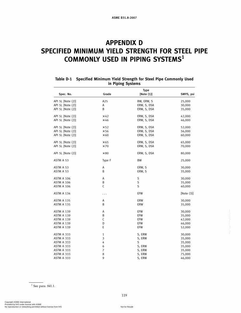
ASME B31.8-2007
APPENDIX DSPECIFIED MINIMUM YIELD STRENGTH FOR STEEL PIPE
COMMONLY USED IN PIPING SYSTEMS1
Table D-1 Specified Minimum Yield Strength for Steel Pipe Commonly Usedin Piping Systems
TypeSpec. No. Grade [Note (1)] SMYS, psi
API 5L [Note (2)] A25 BW, ERW, S 25,000API 5L [Note (2)] A ERW, S, DSA 30,000API 5L [Note (2)] B ERW, S, DSA 35,000
API 5L [Note (2)] �42 ERW, S, DSA 42,000API 5L [Note (2)] �46 ERW, S, DSA 46,000
API 5L [Note (2)] �52 ERW, S, DSA 52,000API 5L [Note (2)] �56 ERW, S, DSA 56,000API 5L [Note (2)] �60 ERW, S, DSA 60,000
API 5L [Note (2)] �65 ERW, S, DSA 65,000API 5L [Note (2)] �70 ERW, S, DSA 70,000
API 5L [Note (2)] �80 ERW, S, DSA 80,000
ASTM A 53 Type F BW 25,000
ASTM A 53 A ERW, S 30,000ASTM A 53 B ERW, S 35,000
ASTM A 106 A S 30,000ASTM A 106 B S 35,000ASTM A 106 C S 40,000
ASTM A 134 . . . EFW [Note (3)]
ASTM A 135 A ERW 30,000ASTM A 135 B ERW 35,000
ASTM A 139 A EFW 30,000ASTM A 139 B EFW 35,000ASTM A 139 C EFW 42,000ASTM A 139 D EFW 46,000ASTM A 139 E EFW 52,000
ASTM A 333 1 S, ERW 30,000ASTM A 333 3 S, ERW 35,000ASTM A 333 4 S 35,000ASTM A 333 6 S, ERW 35,000ASTM A 333 7 S, ERW 35,000ASTM A 333 8 S, ERW 75,000ASTM A 333 9 S, ERW 46,000
1 See para. 841.1.
119
Copyright ASME International Provided by IHS under license with ASME
Not for ResaleNo reproduction or networking permitted without license from IHS
--`,,```,,,,````-`-`,,`,,`,`,,`---

ASME B31.8-2007
Table D-1 Specified Minimum Yield Strength for Steel Pipe Commonly Usedin Piping Systems (Cont’d)
TypeSpec. No. Grade [Note (1)] SMYS, psi
ASTM A 381 Class Y-35 DSA 35,000
ASTM A 381 Class Y-42 DSA 42,000ASTM A 381 Class Y-46 DSA 46,000ASTM A 381 Class Y-48 DSA 48,000ASTM A 381 Class Y-50 DSA 50,000
ASTM A 381 Class Y-52 DSA 52,000ASTM A 381 Class Y-56 DSA 56,000ASTM A 381 Class Y-60 DSA 60,000
ASTM A 381 Class Y-65 DSA 65,000
GENERAL NOTE: This table is not complete. For the minimum specified yield strength of other gradesand grades in other approved specifications, refer to the particular specification.
NOTES:(1) Abbreviations: BW p furnace buttwelded; DSA p double submerged-arc welded; EFW p electric
fusion welded; ERW p electric resistance welded; FW p flash welded; S p seamless.(2) Intermediate grades are available in API 5L.(3) See applicable plate specification for SMYS.
Long-Term Hydrostatic Strength Values for Thermoplastic Pipes Covered by ASTM D 2513. The valuesapply only to materials and pipes meeting all the requirements of the basic materials and ASTM D2513. They are based on engineering test data obtained in accordance with ASTM D 1599 and ana-lyzed in accordance with ASTM D 2837. A list of commercial compounds meeting these requirements ispublished yearly by the Plastics Pipe Institute.
Plastic Pipe Material Long-Term Hydrostatic StrengthDesignation (D 2513) at 73°F, psi
PB 2110 2,000PE 2406 1,250PE 3408 1,600
PVC 1120 4,000PVC 1220 4,000PVC 2110 2,000PVC 2116 3,150
Long-Term Hydrostatic Strength for Reinforced Thermosetting Pipes Covered by ASTM D 2517 is 11,000psi. The values apply only to materials and pipes meeting all the requirements of the basic materialsand ASTM D 2517. They are based on engineering test data obtained in accordance with ASTM D 1599and analyzed in accordance with ASTM D 2837.
120
Copyright ASME International Provided by IHS under license with ASME
Not for ResaleNo reproduction or networking permitted without license from IHS
--`,,```,,,,````-`-`,,`,,`,`,,`---

ASME B31.8-2007
APPENDIX EFLEXIBILITY AND STRESS INTENSIFICATION FACTORS
Table E-1 begins on following page.
121
Copyright ASME International Provided by IHS under license with ASME
Not for ResaleNo reproduction or networking permitted without license from IHS
--`,,```,,,,````-`-`,,`,,`,`,,`---

(07)
ASME B31.8-2007
Table E-1 Flexibility Factor, k, and Stress Intensification Factor, i
Stress IntensificationFactor, i [Notes (1) and (2)]Flexibility Flexibility
Factor, Out-plane, In-plane, Characteristic,Description k io ii h Sketch
Welding elbow or pipe bend 1.65h
0.75
h2⁄3
0.9
h2⁄3
T R1
r22[Notes (1)–(5)]
Closely spaced miter bend [Notes(1), (2), (3), and (5)]
1.52
h5/6
0.9
h2/3
0.9
h2/3
cot �2
Ts
r22
s < r2 (1 + tan � )
Single miter bend or widelyspaced miter bend 1.52
h5/6
0.9
h2/3
0.9
h2/3
1 + cot �2
Tr2s ≥ r2 (1 + tan � )
[Notes (1), (2), and (5)]
Welding tee per ASME B16.9 withro ≥ d⁄8 1
0.9
h2/33⁄4io + 1⁄4 4.4
Tr2Tc ≥ 1.5 T
[Notes (1), (2), and (6)]
Reinforced fabricated tee withpad or saddle [Notes (1), (2), 1
0.9
h2/33⁄4 io +1⁄4
(T + 1⁄2 te)5/2
T3/2 r2(7)–(9)]
Unreinforced fabricated tee1
0.9
h2/33⁄4 io +1⁄4
Tr2[Notes (1), (2), and (9)]
Extruded outletro ≥ 0.05d
10.9
h2/33⁄4 io + 1⁄4 �1 +
ro
r2�Tr2Tc < 1.5 T
[Notes (1), (2), and (6)]
Welded-in contour insertro ≥ d⁄8 1
0.9
h2/33⁄4 io + 1⁄4 4.4
Tr2Tc ≥ 1.5 T
[Notes (1), (2), and (10)]
Branch welded-on fitting (inte-grally reinforced) [Notes (1), 1
0.9
h2/3
0.9
h2/33.3
Tr2(2), (9), and (11)]
122
Copyright ASME International Provided by IHS under license with ASME
Not for ResaleNo reproduction or networking permitted without license from IHS
--`,,```,,,,````-`-`,,`,,`,`,,`---

ASME B31.8-2007
Table E-1 Flexibility Factor, k, and Stress Intensification Factor, i (Cont’d)
Flexibility Stress IntensificationFactor, Factor,
Description k i Sketch
Buttweld [Notes (1) and (12)]
1 1.0T ≥ 0.237 in.,
�max. ≤ 1⁄16 in.,and �avg/T ≤ 0.13
Buttweld [Notes (1) and (12)]
T ≥ 0.237 in.,�max. ≤ 1⁄8 in., 1.9 max. or δ
T T
and �avg/T p any value 1 [0.9 + 2.7(�avg/T)],but not less than
1.0Buttweld [Notes (1) and (12)]
T ≤ 0.237 in.,�max. ≤ 1⁄16 in.,
and �avg/T ≤ 0.33
1 1.9 max. orTapered transition per
ASME B16.25 1.3 + 0.0036Do
T+ 3.6
�
T[Note (1)]Do
T
1 2.0 max. or
Concentric reducer per 0.5 + 0.01� �Do2
T2 �1/2
ASME B16.9 [Notes (1) and(13)] Do2
α
Do1
T2
T1
Double-welded slip-on flange 1 1.2[Note (14)]
Socket welding flange or fit- 1 2.1 max or 2.1 T/Cx butting [Notes (14) and (15)] not less than 1.3
Lap joint flange (with ASME 1 1.6B16.9 lap joint stub)[Note (14)]
Threaded pipe joint or 1 2.3threaded flange [Note (14)]
Corrugated straight pipe, or 5 2.5corrugated or creased bend[Note (16)]
123
Copyright ASME International Provided by IHS under license with ASME
Not for ResaleNo reproduction or networking permitted without license from IHS
--`,,```,,,,````-`-`,,`,,`,`,,`---

ASME B31.8-2007
Table E-1 Flexibility Factor, k, and Stress Intensification Factor, i (Cont’d)
124
Copyright ASME International Provided by IHS under license with ASME
Not for ResaleNo reproduction or networking permitted without license from IHS
--`,,```,,,,````-`-`,,`,,`,`,,`---

ASME B31.8-2007
Table E-1 Flexibility Factor, k, and Stress Intensification Factor, i (Cont’d)
NOTES:(1) The nomenclature is as follows:
R1 p bend radius of welding elbow or pipe bend, in. (mm)T p nominal wall thickness of piping component, in. (mm)
p for elbows and miter bends, the nominal wall thickness of the fitting, in. (mm)p for welding tees, the nominal wall thickness of the matching pipe, in. (mm)p for fabricated tees, the nominal wall thickness of the run or header (provided that if thickness is greater than that of matching
pipe, increased thickness must be maintained for at least one run outside diameter to each side of the branch outside diame-ter), in. (mm)
Tc p the crotch thickness of tees, in. (mm)d p outside diameter of branch, in. (mm)r0 p radius of curvature of external contoured portion of outlet, measured in the plane containing the axes of the header and
branch, in. (mm)r2 p mean radius of matching pipe, in. (mm)s p miter spacing at centerline, in. (mm)te p pad or saddle thickness, in. (mm)� p reducer cone angle, deg� p one-half angle between adjacent miter axes, deg
(2) The flexibility factor, k, applies to bending in any plane. The flexibility factors, k, and stress intensification factors, i, shall not be lessthan unity; factors for torsion equal unity. Both factors apply over the effective arc length (shown by heavy centerlines in thesketches) for curved and miter bends and to the intersection point for tees.
The values of k and i can be read directly from Chart A by entering with the characteristic, h, computed from the formulas given.(3) Where flanges are attached to one or both ends, the values of k and i shall be corrected by the factors, Cu, which can be read
directly from Chart B, entering with the computed h.(4) The designer is cautioned that cast buttwelded fittings may have considerably heavier walls than that of the pipe with which they are
used. Large errors may be introduced unless the effect of these greater thicknesses is considered.(5) In large diameter thin-wall elbows and bends, pressure can significantly affect the magnitudes of k and i. To correct values from the
table, divide k by
�1 + 6 �PEe� �r2
T �7/3
�R1
r2�1/3
�divide i by
�1 + 3.25 �PEe� �r2
T �5/2
�R1
r2�2/3
�where
Ee p cold modulus of elasticityP p gage pressure
(6) If the number of displacement cycles is less than 200, the radius and thickness limits specified need not be met. When the radiusand thickness limits are not met and the number of design cycles exceeds 200, the out-plane and in-plane stress intensification fac-tors shall be calculated as 1.12/h2/3 and (0.67/h2/3) + 1⁄4, respectively.
(7) When te > 11⁄2T, use h p 4.05T/r2.(8) The minimum value of the stress intensification factor shall be 1.2.(9) When the branch-to-run diameter ratio exceeds 0.5, but is less than 1.0, and the number of design displacement cycles exceeds
200, the out-plane and in-plane stress intensification factors shall be calculated as 1.8/h2/3 and (0.67/h2/3) + 1⁄4, respectively,unless the transition weld between the branch and run is blended to a smooth concave contour. If the transition weld is blended toa smooth concave contour, the stress intensification factors in the table still apply.
(10) If the number of displacement cycles is less than 200, the radius and thickness limits specified need not be met. When the radiusand thickness limits are not met and the number of design displacement cycles exceeds 200, the out-plane and in-plane stress inten-sification factors shall be calculated as 1.8/h2/3 and (0.67/h2/3) + 1⁄4, respectively.
(11) The designer must be satisfied that this fabrication has a pressure rating equivalent to straight pipe.(12) The stress intensification factors apply to girth butt welds between two items for which the wall thicknesses are between 0.875T and
1.10T for an axial distance of �Do T · Do and T are nominal outside diameter and nominal wall thickness, respectively. �avg is theaverage mismatch or offset.
125
Copyright ASME International Provided by IHS under license with ASME
Not for ResaleNo reproduction or networking permitted without license from IHS
--`,,```,,,,````-`-`,,`,,`,`,,`---

ASME B31.8-2007
Table E-1 Flexibility Factor, k, and Stress Intensification Factor, i (Cont’d)(13) The equation applies only if the following conditions are met.
(a) Cone angle � does not exceed 60 deg, and the reducer is concentric.(b) The larger of Do1/T and Do2/T does not exceed 100.(c) The wall thickness is not less than T1 throughout the body of the reducer, except in and immediately adjacent to the cylindrical por-
tion on the small end, where the thickness shall not be less than T2.(14) For some flanged joints, leakage may occur at expansion stresses otherwise permitted herein. The moment to produce leakage of a
flanged joint with a gasket having no self-sealing characteristics can be estimated by the equation.
ML p (C/4) (Sb Ab − PAp)
Ab p total area of flange bolts, in.2 (mm3)Ap p area to outside of gasket contact, in.2 (mm2)C p bolt circle, in. (mm)
ML p moment to produce flange leakage, in.-lb (mm·N)P p internal pressure, psi (MPa)
Sb p bolt stress, psi (MPa)(15) Cx is the fillet weld length. For unequal lengths, use the smaller leg for Cx.(16) Factors shown apply to bending. Flexibility factor for torsion equals 0.9.
126
Copyright ASME International Provided by IHS under license with ASME
Not for ResaleNo reproduction or networking permitted without license from IHS
--`,,```,,,,````-`-`,,`,,`,`,,`---

(07)
ASME B31.8-2007
APPENDIX FEXTRUDED HEADERS AND WELDED BRANCH CONNECTIONS1
F-1 EXTRUDED HEADERS
Definitions and limitations applicable to Figs. F-1through F-4 are as follows:
D p outside diameter of runDc p corroded internal diameter of runDo p corroded internal diameter of extruded outlet
measured at the level of the outside surfaceof run
L p height of the reinforcement zonep 0.7 �dT0
Tb p actual thickness of branch wall, not includingcorrosion allowance
Tr p actual thickness of the run wall, not includingthe corrosion allowance
To p corroded finished thickness of extruded outletmeasured at a height equal to ro above the out-side surface of the run
d p outside diameter of branch pipedc p corroded internal diameter of branch pipeho p height of the extruded lip. This must be equal
to or greater than ro, except as shown in limita-tion (b) of ro below.
rl p half width of reinforcement zone (equal to Do)ro p radius of curvature of external contoured por-
tion of outlet measured in the plane containingthe axes of the run and branch. This is subjectto the following limitations:
(a) Minimum Radius. This dimension shallnot be less than 0.05d, except that on branchdiameters larger than 30 in., it need not exceed1.50 in.
(b) Maximum Radius. For outlet pipe sizesNPS 8 and larger, this dimension shall notexceed 0.10d + 0.50 in. For outlet pipe sizessmaller than NPS 8, this dimension shall notbe greater than 1.25 in.
(c) When the external contour contains morethan one radius, the radius on any arc sectorof approximately 45 deg shall meet the require-ments of (a) and (b) above.
(d) Machining shall not be employed to meetthe above requirements.
tb p required thickness of branch pipe according tothe steel pipe design formula of para. 841.11,but not including any thickness for corrosion
1 See para. 831.6.
127
tr p required thickness of the run according to thesteel pipe design formula para. 841.11, but notincluding any allowance for corrosion orunder-thickness tolerance
F-2 EXAMPLES ILLUSTRATING THE APPLICATIONOF THE RULES FOR REINFORCEMENT OFWELDED BRANCH CONNECTIONS
F-2.1 Example 1
An NPS 8 outlet is welded to an NPS 24 header. Theheader material is API 5LX 46 with a 0.312-in. wall. Theoutlet is API 5L Grade B (Seamless) Schedule 40 with a0.322-in. wall. The working pressure is 650 psig. Thefabrication is in Class Location 1. Using para. 841.1, thejoint efficiency is 1.00. The temperature is 100°F. Designfactors F p 0.60, E p 1.00, and T p 1.00. For dimensions,see Fig. F-6.
F-2.11 Header. Nominal wall thickness required:
t pPD
2 SFETp
650 � 242 � 46,000 � 0.60 � 1.00 � 1.00
p 0.283 in.
Excess thickness in header wall:
H − t p 0.312 − 0.283 p 0.029 in.
F-2.12 Outlet. Nominal wall thickness required:
tb p650 � 8.625
2 � 35,000 � 0.60 � 1.00 � 1.00p 0.133 in.
Excess thickness in outlet wall:
B − tb p 0.322 − 0.133 p 0.189 in.
d p inside diameter of opening p 8.625 − 2 � 0.322p 7.981 in.
F-2.13 Reinforcement Required
AR p dt p 7.981 � 0.283 p 2.259 in.2
F-2.14 Reinforcement Provided by Header
A1 p (H − t) d p 0.029 � 7.981 p 0.231 in.2
F-2.15 Effective Area in Outlet
Height L p 21/2 B + M (assume 1/4-in. pad)p (21/2 � 0.322) + 0.25 p 1.055 in.
Copyright ASME International Provided by IHS under license with ASME
Not for ResaleNo reproduction or networking permitted without license from IHS
--`,,```,,,,````-`-`,,`,,`,`,,`---

ASME B31.8-2007
or L p 21/2H p 2.5 � 0.312 p 0.780 in. Use L p 0.780 in.
A2 p 2 (B − tb) L p 2 � 0.189 � 0.780p 0.295 in.2
This must be multiplied by 35,000/46,000. [See para.831.41(f).]
Effective A′2 p 0.295 �35,00046,000
p 0.224 in.2
Required area:
A3 p AR − A1 − A′2p 2.259 − 0.231 − 0.224 p 1.804 in.2
Use a reinforced plate that is 0.250 in. thick (minimumpracticable) � 15.5 in. in diameter.
Area p (15.500 − 8.625) � 0.250 p 1.719 in.2
Fillet welds (assuming two 1⁄4-in. welds each side):
1/2 (0.25 � 0.25) � 4 p 0.125 in.2
Total A3 provided p 1.844 in.2
See also Fig. F-5.
F-2.2 Example 2
An NPS 16 outlet is welded to an NPS 24 header. Theheader material is API 5LX 46 with a 0.312-in. wall. Theoutlet is API 5L Grade B (Seamless) Schedule 20 with a0.312-in. wall. The working pressure is 650 psig. Thefabrication is in Class Location 1. By para. 831.42, thereinforcement must be of the complete encirclementtype. Using para. 841.1, the joint efficiency is 1.00. Thetemperature is 100°F. Design factors F p 0.60, E p 1.00,and T p 1.00. For dimensions, see Fig. F-7.
F-2.21 Header. Nominal wall thickness required:
t pPD
2 SFETp
650 � 242 � 46,000 � 0.60 � 1.00 � 1.00
p 0.283 in.
Excess thickness in header wall:
H − t p 0.312 − 0.283 p 0.029 in.
F-2.22 Outlet. Nominal wall thickness required:
tb p650 � 16
2 � 35,000 � 0.60 � 1.00 � 1.00p 0.248 in.
Excess thickness in outlet wall:
B − tb p 0.312 − 0.248 p 0.064 in.
128
d p inside diameter of opening p 16.000 − 2 � 0.312p 15.376 in.
F-2.23 Reinforcement Required
AR p dt p 15.376 � 0.283 p 4.351 in.2
F-2.24 Reinforcement Provided
A1 p (H − t) d p 0.029 � 15.376 p 0.446 in.2
F-2.25 Effective Area in Outlet
Height L p 21/2 B + M (assume 5/16-in. plate)p (2.5 � 0.312) + 0.312 p 1.092 in.
or
L p 21/2H p 2.5 � 0.312 p 0.780 in. Use L p 0.780 in.
A2 p 2 (B − tb) L p 2 � 0.064 � 0.780p 0.100 in.2
This must be multiplied by 35,000/46,000. [See para.831.4(f).]
Effective A′2 p 0.100 � 35,000/46,000 p 0.076 in.2
Required area:
A3 p AR − A1 − A′2p 4.351 − 0.446 − 0.076 p 3.829 in.2
Approximate required thickness of reinforcement:
3.829 � (30 − 16) p 0.274 in.
Use a 0.312-in. plate minimum required length(neglecting welds):
3.829 � 0.312 p 12.272 in.
16 + 12.272 p 29 in. (rounded to the next higher wholenumber)
Use a plate that is 29 in. long:
Area p 0.312 � (29 − 16) p 4.056 in.2
Two 1⁄4-in. welds to outlet:
1/2 � (0.25 � 0.25) � 2 p 0.063 in.2
Total A3 provided p 4.119 in.2
The use of end welds is optional. See Fig. I-3.
Copyright ASME International Provided by IHS under license with ASME
Not for ResaleNo reproduction or networking permitted without license from IHS
--`,,```,,,,````-`-`,,`,,`,`,,`---

ASME B31.8-2007
Fig. F-1
Fig. F-2
GENERAL NOTE: Sketch to show method of establishing To when the taper encroaches on the crotch radius.
Fig. F-3
129
Copyright ASME International Provided by IHS under license with ASME
Not for ResaleNo reproduction or networking permitted without license from IHS
--`,,```,,,,````-`-`,,`,,`,`,,`---

ASME B31.8-2007
Fig. F-4
130
Copyright ASME International Provided by IHS under license with ASME
Not for ResaleNo reproduction or networking permitted without license from IHS
--`,,```,,,,````-`-`,,`,,`,`,,`---

ASME B31.8-2007
Fig. F-5 Rules for Reinforcement of Welded Branch Connections
131
Copyright ASME International Provided by IHS under license with ASME
Not for ResaleNo reproduction or networking permitted without license from IHS
--`,,```,,,,````-`-`,,`,,`,`,,`---

ASME B31.8-2007
Fig. F-6
Fig. F-7
132
Copyright ASME International Provided by IHS under license with ASME
Not for ResaleNo reproduction or networking permitted without license from IHS
--`,,```,,,,````-`-`,,`,,`,`,,`---

ASME B31.8-2007
APPENDIX GTESTING OF WELDERS LIMITED TO WORK ON LINES
OPERATING AT HOOP STRESSES OF LESS THAN 20% OF THESPECIFIED MINIMUM YIELD STRENGTH1
G-1 TEST PROCEDURES
(a) An initial test shall qualify a welder for work.Thereafter, the welder’s work shall be checked either byrequalification at 1-year intervals or by cutting out andtesting production work at least every 6 months.
(b) The test may be made on pipe of any diameter12 in. or smaller. The test weld shall be made with thepipe in a horizontal fixed position so that the test weldincludes at least one section of overhead positionwelding.
(c) The beveling, root opening, and other details mustconform to the procedure specification under which thewelder is qualified.
(d) The test weld shall be cut into four coupons andsubjected to the root bend test. If as a result of this test,a crack develops in the weld material or between theweld and base metal more than 1⁄8 in. long in any direc-tion, this shall be cause for rejection. Cracks occurringon the corner of the specimen during testing shall notbe considered. If not more than one coupon is rejected,the weld is to be considered acceptable.
(e) Welders who are to make welded service line con-nections to mains shall be required to pass the followingtests satisfactorily:
(1) Weld a service line connection fitting to a pipesection having the same diameter as a typical main. Thisweld shall be made in the same position as this type ofweld is made in the field.
(2) The weld shall be tested by attempting to breakthe fitting off the run pipe by any available means(knocking it off).
A sample shall be rejected if the broken weld at thejunction of the fitting and run pipe shows incompletefusion, overlap, or poor penetration.
1 See para. 823.11.
133
(f) For the periodic checking of welders who workon small service lines only (2 in. or smaller in diameter),the following special field test may be employed. Thistest should not be used as a substitute for the originalqualifying test.
Two sample welds made by the welder under testshall be taken from steel service line. Each sample shallbe cut 8 in. long with the weld located approximatelyin the center. One sample shall have the ends flattenedand the entire joint subjected to the tensile strength test.Failure must be in the parent metal and not adjacent toor in the weld metal to be acceptable. The second sampleshall be centered in the guided bend testing machineand bent to the contour of the die for a distance of 2 in.on each side of the weld. The sample to be acceptablemust show no breaks or cracks after removal from thebending machine.
When a tensile strength testing machine is not avail-able, two bend test samples will be acceptable in lieuof one tension and one bending test.
(g) Tests for Copper Joints. Personnel who are to workon copper piping should pass the following test satisfac-torily.
A brazed or soldered copper bell joint should be madeon any size of copper pipe used, with the axis of thepipe stationary in the horizontal position. The joint sowelded is to be sawed open longitudinally at the top ofthe pipe (the top being the uppermost point on thecircumstance at time joint is brazed). The joint shouldbe spread apart for examination. The bell end of thejoint must be completely bonded. The spigot end ofthe joint must give evidence that the brazing alloy hasreached at least 75% of the total area of the telescopedsurfaces. At least 50% of the length at the top of thejoint must be joined.
(h) Records shall be kept of the original tests and allsubsequent tests conducted on the work of each welder.
Copyright ASME International Provided by IHS under license with ASME
Not for ResaleNo reproduction or networking permitted without license from IHS
--`,,```,,,,````-`-`,,`,,`,`,,`---

ASME B31.8-2007
APPENDIX HFLATTENING TEST FOR PIPE1
H-1 TEST PROCEDURES
(a) The flattening test shall be made on standardweight and extra strong pipe over NPS 2. It shall notbe required for double extra strong pipe.
(b) For a lap-welded and buttwelded pipe, the testsection shall be 4 in. to 6 in. in length, and the weldshall be located 45 deg from the line of direction of theapplied force.
(c) For electric-resistance welded pipe, both crop endsfrom each length of pipe shall be flattened betweenparallel plates with the weld at the point of maximumbending until the opposite walls of the pipe meet. Noopening in the weld shall take place until the distancebetween the plates is less than two-thirds of the originaloutside diameter of the pipe. No cracks or breaks in themetal other than in the weld shall occur until the distancebetween the plates is less than one-third of the originaloutside diameter of the pipe, but in no case less thanfive times the thickness of the pipe wall. Evidence oflamination or burnt material shall not develop duringthe entire flattening process, and the weld shall not showinjurious defects.
(d) For seamless pipe the test section shall be not lessthan 21⁄2 in. in length.
1 See para. 817.13(b).
134
(e) The test shall consist of flattening a section of pipebetween parallel plates until the opposite walls meet.For welded pipe, no opening in the weld shall take placeuntil the distance between the plates is less than three-fourths of the original outside diameter for buttweldedpipe, and two-thirds of the outside diameter for lap-welded and electric-resistance welded pipes. No cracksor breaks in the metal other than in the weld shall occuruntil the distance between the plates is less than three-fifths of the outside diameter for buttwelded pipe, andone-third of the outside diameter for lap-welded andelectric-resistance welded (Grades A and B) pipes. Forseamless (Grades A and B) pipe, no breaks or cracks inthe metal shall occur until the distance between theplates is less than that shown below:
H p(1 + e) te + t/D
whereD p actual outside diameter of pipes, in. (2.375 in.
nominal)H p distance between flattening plates, in.e p deformation per unit length (constant for a
given grade of steel, 0.09 for Grade A and 0.07for Grade B)
t p nominal wall thickness of pipe, in.
Copyright ASME International Provided by IHS under license with ASME
Not for ResaleNo reproduction or networking permitted without license from IHS
--`,,```,,,,````-`-`,,`,,`,`,,`---

ASME B31.8-2007
APPENDIX IEND PREPARATIONS FOR BUTTWELDING
I-1 EXPLANATORY NOTES
I-1.1 General
This Appendix applies to end preparation for butt-welding sections having unequal thicknesses andunequal specified minimum yield strengths. See Figs. I-1through I-4.
(a) The sketches in Fig. I-5 illustrate acceptable prepa-rations for joining pipe ends by buttwelding for materi-als having unequal wall thicknesses and/or withunequal strengths (specified minimum yield strength).
(b) The thickness of the sections to be joined beyondthe joint design area shall comply with the designrequirements of this Code.
(c) When the specified minimum yield strengths ofthe sections to be joined are unequal, the deposited weldmetal shall have mechanical properties at least equal tothose of the section having the higher strength.
(d) The transition between ends of unequal thicknessmay be accomplished by taper or welding as illustratedor by means of a prefabricated transition ring.
(e) Sharp notches or grooves at the edge of the weldwhere it joins a slanted surface shall be avoided.
(f) For joining unequal thicknesses of equal specifiedminimum yield strengths, the rules given herein apply,except there is no minimum angle limit to the taper.
(g) The maximum thickness, tD, for design purposesshall not be greater than 1.5t.
I-1.2 Unequal Internal Diameters
(a) For piping to operate at hoop stresses of less than20% of specified minimum yield strength, if the nominalwall thicknesses of the adjoining ends do not vary morethan 1⁄8 in., no special treatment is necessary providedadequate penetration and bond is accomplished in weld-ing. If the offset is greater than 1⁄8 in., the followingparagraphs will apply.
(b) For Hoop Stress Levels 20% or More of the SpecifiedMinimum Yield Strength
(1) If the nominal wall thickness of the adjoiningends does not vary more than 3⁄32 in., no special treatment
135
is necessary, provided full penetration and bond isaccomplished in welding. See sketch (a) of Fig. I-5.
(2) Where the nominal internal offset is greater than3⁄32 in. and there is no access to the inside of the pipefor welding, the transition must be made by a taper cuton the inside end of the thicker section. See sketch (b)of Fig. I-5. The taper angle shall be not greater than30 deg nor less than 14 deg.
(3) Where the nominal internal offset is more than3⁄32 in. but does not exceed one-half the thinner section,and there is access to the inside of the pipe for welding,the transition may be made with a tapered weld asshown in sketch (c) of Fig. I-5. The land on the thickersection must be equal to the offset plus the land onabutting section.
(4) Where the nominal internal offset is more thanone-half the thinner section and there is access to theinside of the pipe for welding, the transition may bemade with a taper cut on the inside end of the thickersection as shown in sketch (b) of Fig. I-5, or by a combina-tion taper weld to one-half the thinner section and ataper cut from that point as shown in sketch (d) ofFig. I-5.
I-1.3 Unequal External Diameters
(a) Where the external offset does not exceed one-half the thinner section, the transition may be made bywelding as shown by sketch (e) of Fig. I-5, provided theangle of rise of the weld surface does not exceed 30 degand both bevel edges are properly fused.
(b) Where there is an external offset exceeding one-half the thinner section, that portion of the offset over1⁄2t shall be tapered as shown in sketch (f) of Fig. I-5.
I-1.4 Unequal Internal and External Diameters
Where there is both an internal and an external offset,the joint design shall be a combination of sketches (a)through (f) of Fig. I-5, i.e., sketch (g). Particular attentionmust be paid to proper alignment under these condi-tions.
See also Fig. I-6 and Table I-1.
Copyright ASME International Provided by IHS under license with ASME
Not for ResaleNo reproduction or networking permitted without license from IHS
--`,,```,,,,````-`-`,,`,,`,`,,`---

ASME B31.8-2007
Fig. I-1 Welding Details for Openings Without Reinforcement Other Than That InHeader and Branch Walls
Fig. I-2 Welding Details for Openings With Localized-Type Reinforcement
136
Copyright ASME International Provided by IHS under license with ASME
Not for ResaleNo reproduction or networking permitted without license from IHS
--`,,```,,,,````-`-`,,`,,`,`,,`---

ASME B31.8-2007
Fig. I-3 Welding Details for Openings With Complete Encirclement Types of Reinforcement
NOTES:(1) Since fluid pressure is exerted on both sides of pipe metal under tee, the pipe metal does not provide reinforcement.(2) Provide hole in reinforcement to reveal leakage in buried welds and to provide venting during welding and heat treatment. [See para.
831.41 (h).] Not required for tee type.
137
Copyright ASME International Provided by IHS under license with ASME
Not for ResaleNo reproduction or networking permitted without license from IHS
--`,,```,,,,````-`-`,,`,,`,`,,`---

(07)
ASME B31.8-2007
Fig. I-3.1 Pressurized Hot Tap Tee Reinforcing Sleeve End Fillet Weld Design
Gap
End face � 1.4 times calculated hoopthickness of sleeve (max.), if required
Pressurized hot tapping teereinforcing sleeve
Pipe wall thickness � t
Fillet weld leg � 1.0t � gap to 1.4t � gap
Effective weld throat � 0.7t to 1.0t
Chamfer/taper � 45 deg min. (approx.)
138
Copyright ASME International Provided by IHS under license with ASME
Not for ResaleNo reproduction or networking permitted without license from IHS
--`,,```,,,,````-`-`,,`,,`,`,,`---

ASME B31.8-2007
Fig.
I-4
Acce
ptab
leCo
mbi
nati
ons
ofPi
peEn
dPr
epar
atio
ns
139
Copyright ASME International Provided by IHS under license with ASME
Not for ResaleNo reproduction or networking permitted without license from IHS
--`,,```,,,,````-`-`,,`,,`,`,,`---

ASME B31.8-2007
Fig. I-5 Acceptable Design for Unequal Wall Thickness
NOTE:(1) No minimum when materials joined have equal specified minimum yield strengths.
140
Copyright ASME International Provided by IHS under license with ASME
Not for ResaleNo reproduction or networking permitted without license from IHS
--`,,```,,,,````-`-`,,`,,`,`,,`---

ASME B31.8-2007
Fig. I-6 Recommended Attachment Details of Flanges
141
Copyright ASME International Provided by IHS under license with ASME
Not for ResaleNo reproduction or networking permitted without license from IHS
--`,,```,,,,````-`-`,,`,,`,`,,`---

ASME B31.8-2007
Table I-1 Lightweight Flanges
Drilling TemplateInside OutsideNominal Outside Diameter, Length Diameter Number Diameter Diameter Approx. Weight
Pipe Diameter, Thickness, B of Hub, of Hub, of and Length of Bolt Each,Size A T [Note (1)] L E Bolts of Bolts Circle lb
6 11 9⁄16 6.72 11⁄4 79⁄16 8 3⁄4 � 21⁄4 91⁄2 138 131⁄2
9⁄16 8.72 11⁄4 911⁄16 8 3⁄4 � 21⁄4 113⁄4 1810 16 11⁄16 10.88 11⁄4 12 12 7⁄8 � 21⁄2 141⁄4 2612 19 11⁄16 12.88 11⁄4 143⁄8 12 7⁄8 � 21⁄2 17 4214 21 3⁄4 14.14 11⁄4 153⁄4 12 1 � 23⁄4 183⁄4 44
16 231⁄23⁄4 16.16 11⁄4 18 16 1 � 23⁄4 211⁄4 58
18 25 3⁄4 18.18 11⁄4 197⁄8 16 11⁄8 � 3 223⁄4 5920 271⁄2
3⁄4 20.20 11⁄4 22 20 11⁄8 � 3 25 6922 291⁄2 1 22.22 13⁄4 241⁄4 20 11⁄4 � 31⁄2 271⁄4 76
24 32 1 24.25 13⁄4 261⁄8 20 11⁄4 � 31⁄2 291⁄2 11326 341⁄4 1 26.25 13⁄4 281⁄2 24 11⁄4 � 31⁄2 313⁄4 12628 361⁄2 1 28.25 13⁄4 301⁄2 28 11⁄4 � 31⁄2 34 13930 383⁄4 1 30.25 13⁄4 321⁄2 28 11⁄4 � 31⁄2 36 152
32 413⁄4 11⁄8 32.25 13⁄4 343⁄4 28 11⁄2 � 4 381⁄2 20634 433⁄4 11⁄8 34.25 13⁄4 363⁄4 32 11⁄2 � 4 401⁄2 21736 46 11⁄8 . . . 13⁄4 383⁄4 32 11⁄2 � 4 423⁄4 23438 483⁄4 11⁄8 . . . 13⁄4 403⁄4 32 11⁄2 � 4 451⁄4 264
40 503⁄4 11⁄8 . . . 13⁄4 43 36 11⁄2 � 4 471⁄4 28042 53 11⁄4 . . . 13⁄4 45 36 11⁄2 � 41⁄4 491⁄2 32844 551⁄4 11⁄4 . . . 21⁄4 47 40 11⁄2 � 41⁄4 513⁄4 34946 571⁄4 11⁄4 . . . 21⁄4 49 40 11⁄2 � 41⁄4 533⁄4 363
48 591⁄2 13⁄8 . . . 21⁄2 51 44 11⁄2 � 41⁄2 56 42650 613⁄4 13⁄8 . . . 21⁄2 53 44 13⁄4 � 43⁄4 581⁄4 45152 64 13⁄8 . . . 21⁄2 55 44 13⁄4 � 43⁄4 601⁄2 47754 661⁄4 13⁄8 . . . 21⁄2 57 44 13⁄4 � 43⁄4 623⁄4 504
60 73 11⁄2 . . . 23⁄4 63 52 13⁄4 � 5 691⁄4 64366 80 11⁄2 . . . 23⁄4 69 52 13⁄4 � 5 76 75472 861⁄2 11⁄2 . . . 23⁄4 75 60 13⁄4 � 5 821⁄2 846
GENERAL NOTES:(a) Lightweight flanges are flat-faced and designed for use with full-face gasket or asbestos sheet gasket extending to the bolt holes.(b) Maximum pressure for lightweight flanges is 25 psi; drilling is the same as Class 125 standard.(c) This table encompasses forged and rolled steel; for further information, refer to ASTM A 105.
NOTE:(1) For nominal pipe sizes 36 through 72, the inside diameter, B, shall be as specified by the purchaser.
142
Copyright ASME International Provided by IHS under license with ASME
Not for ResaleNo reproduction or networking permitted without license from IHS
--`,,```,,,,````-`-`,,`,,`,`,,`---

ASME B31.8-2007
APPENDIX JCOMMONLY USED CONVERSION FACTORS1
Table J-1 Commonly Used Conversion Factors
Quantity Conversion Factor
Plane angle deg to rad 1.745 329E−02
Length in. to m 2.54E−02 (1)ft to m 3.048E−01 (1)mile to m 1.609 344E+03 (1)
Area in.2 to m2 6.451 600E−04 (1)ft2 to m2 9.290 304E−02 (1)
Volume ft3 to m3 2.831 685E−02U.S. gal to m3 3.785 412E−03in.3 to m3 1.638 706E−05oz (fluid, U.S.) to m3 2.957 353E−05liter to m3 1.000 000E−03
Velocity ft/min to m/s 5.08E−03 (1)ft/sec to m/s 3.048E−01 (1)km/h to m/s 2.777 778E−01mi/hr to m/s 4.470 4E−01 (1)mi/hr to km/h 1.609 344E+00 (1)
Mass oz (avoir) to kg 2.834 952E−02lb (avoir) to kg 4.535 924E−01slug to kg 1.459 390E+01
Acceleration ft/sec2 to m/s2 3.048E−01 (1)std. grav. to m/s2 9.806 65E+00 (1)
Force kgf to N 9.806 65E+00 (1)lbf to N 4.448 222E+00poundal to N 1.382 550E−01
Bending, torque kgf · m to N · m 9.806 65E+00 (1)lbf-in. to N · m 1.129 848E−01lbf-ft to N · m 1.355 818E+00
Pressure (1) psi to bar 6.894 757E−02Pa to bar 1.000E−05kPa to bar 1.000E−02
1 Extracted partially from ASME SI-1.
143
Copyright ASME International Provided by IHS under license with ASME
Not for ResaleNo reproduction or networking permitted without license from IHS
--`,,```,,,,````-`-`,,`,,`,`,,`---

ASME B31.8-2007
Table J-1 Commonly Used Conversion Factors (Cont’d)
Quantity Conversion Factor
Stress (1) psi to MPa 6.894 757E−03kips/in.2 to MPa 6.894 757E+00N/mm2 to MPa 1.000E+00
Energy, work Btu (IT) to J 1.055 056E+03Calorie (IT) to J 4.186 8E+00 (1)lbf-ft to J 1.355 818E+00
Power hp (550 ft lbf/sec) to W 7.456 999E+02
Temperature (1) °C to K tK p tC + 273.15°F to K tK p (tF + 459.67)/1.8°F to °C tC p (tF − 32)/1.8
Temperature °C to K 1.0E+00 (1)interval °F to K or °C 5.555 556E−01
GENERAL NOTES:(a) For other commonly used conversion factors, refer to ASTM E 380.(b) The factors are written as a number greater than one and less than 10 with six or less decimal
places. The number is followed by the letter E (for exponent), a plus or minus symbol, and two dig-its that indicate the power of 10 by which the number must be multiplied to obtain the correctvalue.For example,
1.745 329E−02 is 1.745 329 � 10−2 or 0.017 453 29
NOTE:(1) Relationships are exact in terms of the base units.
144
Copyright ASME International Provided by IHS under license with ASME
Not for ResaleNo reproduction or networking permitted without license from IHS
--`,,```,,,,````-`-`,,`,,`,`,,`---

ASME B31.8-2007
Table J-2 List of SI Units For Use With B31.8 Code
Other Units orQuantity Unit [Note (1)] Symbol Limitations
Space and Time
plane angle radian rad degree (decimalized)solid angle steradian sr . . .length meter m nautical mile (navigation only)area square meter m2 . . .volume cubic meter m3 liter (L) for liquid only
(limit use to L and mL;cc shall not be used)
time second s minute (min), hour (h), day(d), week, and year
angular velocity radian per second rad/s . . .velocity meter per second m/s kilometer per hour (km/h) for
vehicle speed, knot for navi-gation only
Periodic and Related Phe-nomena
frequency hertz Hz (hertz p cycle per second)rotational speed radian per second rad/s revolutions per second (r/s),
revolutions per minute (r/min)
Mechanics
mass kilogram kg . . .density kilogram per cubic meter kg/m3 . . .momentum kilogram-meter per second kg · m/s . . .moment of momentum kilogram-square meter per kg · m2/s . . .
secondangular momentum kilogram-square meter per kg · m2/s . . .
secondacceleration meter per second squared m/s2 . . .moment of inertia kilogram-square meter kg · m2 . . .force newton N . . .moment of force (torque) newton-meter N · m . . .pressure bar bar (pascal p newton per square
meter)stress megapascal MPa . . .viscosity (dynamic) pascal-second Pa · s . . .viscosity (kinematic) square meter per second m2/s . . .surface tension newton per meter N/m . . .energy, work joule J kilowatt-hour (kW · h)power watt W . . .impact strength joule J . . .
145
Copyright ASME International Provided by IHS under license with ASME
Not for ResaleNo reproduction or networking permitted without license from IHS
--`,,```,,,,````-`-`,,`,,`,`,,`---

ASME B31.8-2007
Table J-2 List of SI Units for Use With B31.8 Code (Cont’d)
Other Units orQuantity Unit [Note (1)] Symbol Limitations
Heat
temperature: thermo- kelvin K degree Celsius (°C)dynamic [Note (2)]
temperature: other than degree Celsius °C kelvin (K)thermodynamic [Note(2)]
linear expansion meter per meter-kelvin K−1 °C−1; mm/(mm · K)coefficient
quantity of heat joule J . . .heat flow rate watt W . . .density of heat flow rate watt per meter squared W/m2 . . .thermal conductivity watt per meter-kelvin W/(m · K) W/(m · °C)coefficient of heat watt per meter-squared-kelvin W/(m2 · K) W/(m2 · °C)
transferheat capacity joule per kelvin J/K J/°Cspecific heat capacity joule per kilogram-kelvin J/(kg · K) J/(kg · °C)specific energy joule per kilogram J/kg . . .specific enthalpy kilojoule per kilogram kJ/kg . . .specific entropy kilojoule per kelvin-kilogram kJ/(K · kg) . . .heat rate kilojoule per kilowatt second kJ/(kW · s) . . .
Electricity and Magnetism
electric current ampere A . . .electric charge coulomb C . . .volume density of charge coulomb per meter cubed C/m3 . . .surface density of charge coulomb per meter squared C/m2 . . .electric field of strength volt per meter V/m . . .electric potential volt V . . .capacitance farad F . . .current density ampere per meter squared A/m2 . . .magnetic field strength ampere per meter A/m . . .magnetic flux density tesla T . . .magnetic flux weber Wb . . .self-inductance henry H . . .permeability henry per meter H/m . . .magnetization ampere per meter A/m . . .
NOTES:(1) Conversion factors between SI and U.S. customary units are given in ASTM E 380.(2) Preferred use for temperature and temperature interval is degrees Celsius (°C), except for thermodynamic and cryogenic work where kel-
vins may be more suitable. For temperature interval, 1 K p 1°C exactly.
146
Copyright ASME International Provided by IHS under license with ASME
Not for ResaleNo reproduction or networking permitted without license from IHS
--`,,```,,,,````-`-`,,`,,`,`,,`---

ASME B31.8-2007
APPENDIX KCRITERIA FOR CATHODIC PROTECTION
Reprinted with permission from the National Association of Corrosion Engineers’ NACE Standard RP0169, Section 6.Asterisk (*) denotes word change from NACE text.
6.1 Introduction
6.1.1 The purpose of this Appendix* is to list crite-ria for cathodic protection which, when complied witheither separately or collectively, will indicate that ade-quate cathodic protection of a metallic system in itselectrolyte has been achieved.
6.2 General
6.2.1 The objective of using cathodic protection isto control the corrosion of metallic surfaces in contactwith electrolyte.
6.2.2 The selection of a particular criterion forachieving the objective in 6.2.1 depends, in part, uponpast experience with similar structures and environ-ments wherein the criterion has been used successfully.
6.2.3 The criteria in Section 6.3 have been devel-oped through laboratory experiment or empiricallydetermined by evaluating data obtained from success-fully operated cathodic protection systems. It is notintended that the operating company* be limited to thesecriteria if it can be demonstrated by other means thatthe control of corrosion has been achieved.
6.2.4 Voltage measurements on pipelines are tobe made with the reference electrode located on theelectrolyte surface as close as feasible to the structuresurface being investigated. Consideration shall be givento voltage (IR) drops other than those across the struc-ture-electrolyte boundary, the presence of dissimilarmetals, and the influence of other structures for validinterpretation of voltage measurements.*
6.2.5 No one criterion for evaluating the effective-ness of cathodic protection has proven to be satisfactoryfor all conditions. Often a combination of criteria isneeded for a single structure.
6.3 Criteria
6.3.1 Steel and Cast Iron Structures
6.3.1.1 A negative (cathodic) voltage of at least0.85 volt as measured between the structure surface anda saturated copper-copper sulfate reference electrode
147
contacting the electrolyte. Determination of this voltageis to be made with the protective current applied.
6.3.1.2 A minimum negative (cathodic) voltageshift of 300 millivolts, produced by the application ofprotective current. The voltage shift is measuredbetween the structure surface and a saturated copper-copper sulfate reference electrode contacting the electro-lyte. This criterion of voltage shift applies to structuresnot in contact with dissimilar metals.
6.3.1.3 A minimum negative (cathodic) polariza-tion voltage shift of 100 millivolts measured between thestructure surface and a saturated copper-copper sulfatereference electrode contacting the electrolyte. This polar-ization voltage shift is to be determined by interruptingthe protective current and measuring the polarizationdecay. When the current is initially interrupted, animmediate voltage shift will occur. The voltage readingafter the immediate shift, shall be used as the base read-ing from which to measure polarization decay.
6.3.1.4 A structure-to-electrolyte voltage at leastas negative (cathodic) as that originally established atthe beginning of the Tafel segment of the E-log-I curve.This structure-to-electrolyte voltage shall be measuredbetween the structure surface and a saturated copper-copper sulfate reference electrode contacting the electro-lyte at the same location where voltage measurementswere taken to obtain the E-log-I-curve.
6.3.1.5 A net protective current from the electro-lyte into the structure surface as measured by an earthcurrent technique applied at predetermined current dis-charge (anodic) points of the structure.
6.3.2 Aluminum Structures
6.3.2.1 A minimum negative (cathodic) voltageshift of 150 millivolts, produced by the application ofprotective current. The voltage shift is measuredbetween the structure surface and a saturated copper-copper sulfate reference electrode contacting the electro-lyte. See precautionary notes in 6.3.2.3 and 6.3.2.4.
6.3.2.2 A minimum negative (cathodic) polariza-tion voltage shift of 100 millivolts, measured between thestructure surface and a saturated copper-copper sulfate
Copyright ASME International Provided by IHS under license with ASME
Not for ResaleNo reproduction or networking permitted without license from IHS
--`,,```,,,,````-`-`,,`,,`,`,,`---

ASME B31.8-2007
reference electrode contacting the electrolyte. This polar-ization voltage shift is to be determined by interruptingthe protective current and measuring polarization decay.When the current is initially interrupted, an immediatevoltage shift will occur. The voltage reading after theimmediate shift shall be used as the base reading fromwhich to measure polarization decay. See precautionarynotes in 6.3.2.3 and 6.3.2.4.
6.3.2.3 PRECAUTIONARY NOTE — ExcessiveVoltages: Notwithstanding the alternative minimum cri-teria in 6.3.2.1 and 6.3.2.2, aluminum, if cathodicallyprotected at voltages in excess of 1.20 volts measuredbetween the structure surface and a saturated copper-copper sulfate reference electrode contacting the electro-lyte and compensated for the voltage (IR) drops otherthan those across the structure-electrolyte boundary,may suffer corrosion resulting from the buildup of alkalion the metal surface. A voltage in excess of 1.20 voltsshould not be used unless previous test results indicateno appreciable corrosion will occur in the particularenvironment.
6.3.2.4 PRECAUTIONARY NOTE — AlkalineSoil Conditions: Since aluminum may suffer from corro-sion under high pH conditions and since application ofcathodic protection tends to increase the pH at the metalsurface, careful investigation or testing should be madebefore applying cathodic protection to stop pittingattack on aluminum structures in environments with anatural pH in excess of 8.0.
6.3.3 Copper Structures
6.3.3.1 A minimum negative (cathodic) polariza-tion voltage shift of 100 millivolts measured between thestructure surface and saturated copper-copper sulfatereference electrode in the electrolyte. This polarizationvoltage shift is to be determined by interrupting theprotective current and measuring the polarization decay.When the current is initially interrupted, immediatevoltage shift will occur. The voltage reading after theimmediate shift shall be used as the base reading fromwhich to measure polarization decay.
148
6.3.4 Dissimilar Metal Structure
6.3.4.1 A negative (cathodic) voltage, between allstructure surfaces and a saturated copper-copper sulfatereference electrode contacting the electrolyte, equal tothat required for the most anodic metal should be main-tained. If amphoteric structures are involved that couldbe damaged by high alkalinity (see precautionary notesin 6.3.2.3 and 6.3.2.4), they should be electrically isolatedwith insulating flanges or the equivalent.
6.4 Alternative Reference Electrodes
6.4.1 Other standard reference electrodes may besubstituted for the saturated copper-copper sulfate ref-erence electrodes. Two commonly used electrodes arelisted below along with their voltage equivalent to−0.85 volt referred to saturated copper-copper sulfatereference electrode:
6.4.1.1 Saturated KCl calomel reference elec-trode: −0.78 volt.
6.4.1.2 Silver-silver chloride reference electrodeused in sea water: −0.80 volt.
6.4.2 In addition to these standard reference elec-trodes, an alternative metallic material or structure maybe used in place of the saturated copper-copper sulfatereference electrode if the stability of its electrode poten-tial is assured and if its voltage equivalent referred to asaturated copper-copper sulfate reference electrode isestablished.
6.5 Special Considerations
6.5.1 Special cases, such as stray currents and strayelectrical gradients, may exist which require the use ofcriteria different from those listed above. Measurementsof current loss and gain on the structure and currenttracing in the electrolyte have been useful in such cases.
6.5.2 Abnormal conditions sometimes exist whereprotection is ineffective or only partially effective. Suchconditions may include elevated temperatures, dis-bonded coatings, shielding, bacterial attack, andunusual contaminants in the electrolyte.
Copyright ASME International Provided by IHS under license with ASME
Not for ResaleNo reproduction or networking permitted without license from IHS
--`,,```,,,,````-`-`,,`,,`,`,,`---

ASME B31.8-2007
APPENDIX LDETERMINATION OF REMAINING STRENGTH OF
CORRODED PIPE1
For steel pipelines operating at hoop stress levels ator above 40% of the specified minimum yield strength,the remaining strength of corroded pipe may be deter-mined by the following analysis. [As provided in section1.7(a) in ASME B31G, the operator may make a morerigorous analysis of the corroded area to determine theremaining strength by performing a fracture mechanicsanalysis based upon established principles and practicesusing the actual profile of the corroded regions.]
(a) Determine depth of corrosion, d. (See Fig. L-1.) Ifd is less than 10% of t, the nominal wall thickness, noreduction in MAOP need be considered. If d is greaterthan 80% of t, consideration should be given to removingthe affected segment from service.
(b) Determine the effective length, L, of corrosionalong the longitudinal axis.
(c) Calculate the nondimensional factor, A:
A p 0.893 L /�Dt
whereD p nominal outside diameter of the pipe, in.
(d) For values of A less than or equal to 4.0,
P′ p 1.1P � 1 −2d
3t
1 −2
3
d
t�A2 + 1�
1 For background information, see ASME B31G, Manual forDetermining the Remaining Strength of Corroded Pipelines.
149
Fig. L-1
whereP p the greater of either the design pressure
(excluding the joint factor) or the establishedMAOP, psig
P′ p the safe maximum pressure for the corrodedarea, psig
except that P′ may not exceed P.(e) For values of A greater than 4.0,
P′ p 1.1P(1 − d/t)
except that P′ may not exceed P.(f) If the established MAOP is equal to or less than
P′, the corroded region may remain in service at theMAOP if protected from further corrosion. If it is greaterthan P′, the MAOP should be reduced so that P′ is notexceeded, or the corroded region should be repaired byone of the methods prescribed in para. 851.4 or replaced.
(07)
Copyright ASME International Provided by IHS under license with ASME
Not for ResaleNo reproduction or networking permitted without license from IHS
--`,,```,,,,````-`-`,,`,,`,`,,`---

ASME B31.8-2007
APPENDIX MGAS LEAKAGE CONTROL CRITERIA1
M-1 SCOPE
This Appendix provides criteria for detection, grad-ing, and control of gas leakage.
M-2 DEFINITIONS (APPLICABLE TO THISAPPENDIX ONLY)
bar hole: hole that is made in the soil or paving for thespecific purpose of testing the subsurface atmospherewith a combustible gas indicator (CGI).
building: any structure that is normally or occasionallyentered by humans for business, residential, or otherpurposes, and in which gas could accumulate.
combustible gas indicator (CGI): a device capable ofdetecting and measuring gas concentrations of the atmo-sphere.
confined space: any subsurface structure, such as vaults,catch basins, or manholes, of sufficient size to accommo-date a person, and in which gas could accumulate.
followup inspection: an inspection performed after arepair has been completed to determine the effectivenessof the repair.
gas associated substructure: a device or facility utilized bya gas company such as a valve box, vault, test box, orvented casing pipe, which is not intended for storing,transmitting, or distributing gas.
LEL: the lower explosive limit of the gas being trans-ported.
prompt action: consists of dispatching qualified personnelwithout delay for evaluating and, where necessary, abat-ing the existing or probable hazard.
reading: repeatable deviation on a CGI or equivalentinstrument, expressed in LEL. Where the reading is inan unvented confined space, consideration should begiven to the rate of dissipation when the space is venti-lated and the rate of accumulation when the space isresealed.
small substructures (other than gas associated substructures):any subsurface structures that are of insufficient size toaccommodate a person, such as telephone and electricalducts and conduit or nongas-associated valve and meterboxes, and in which gas could accumulate or migrate.
1 See para. 852.2.
150
tunnel: a subsurface passageway large enough for a per-son to enter and in which gas could accumulate.
M-3 LEAKAGE SURVEY AND TEST METHODS
(a) The following gas leakage surveys and test meth-ods may be employed, as applicable, singly or in combi-nation, in accordance with written procedures:
(1) surface gas detection survey(2) subsurface gas detector survey (including bar
hole surveys)(3) vegetation survey(4) pressure drop test(5) bubble leakage test(6) ultrasonic leakage test
Other survey and test methods may be employed ifthey are deemed appropriate and are conducted inaccordance with procedures that have been tested andproven to be at least equal to the methods listed in thissection.
(b) Surface Gas Detection Survey(1) Definition. This survey is a continuous sam-
pling of the atmosphere at or near ground level forburied gas facilities and adjacent to aboveground gasfacilities with a gas detector system capable of detectinga concentration of 50 ppm of gas in air at any samplingpoint.
(2) Procedure. Equipment used to perform thesesurveys may be portable or mobile. For buried piping,sampling of the atmosphere shall take place, where prac-tical, at no more than 2 in. above the ground surface.In areas where the piping is under pavement, samplingsshall also be at curb line(s), available ground surfaceopenings (such as manholes, catch basins, sewer, power,and telephone duct openings, fire and traffic signalboxes, or cracks in the pavement or sidewalk), or otherinterfaces where the venting of gas is likely to occur.Sampling shall be adjacent to the exposed piping.
(3) Utilization. The use of this survey method maybe limited by adverse conditions (such as excessivewind, excessive soil moisture, or surface sealing by iceor water).
The survey shall be conducted at speeds slow enoughto allow an adequate sample to be continuously obtainedby placement of equipment intakes over the most logicalventing locations, giving consideration to the location ofgas facilities and any adverse conditions that might exist.
Copyright ASME International Provided by IHS under license with ASME
Not for ResaleNo reproduction or networking permitted without license from IHS
--`,,```,,,,````-`-`,,`,,`,`,,`---

ASME B31.8-2007
(c) Subsurface Gas Detection Survey(1) Definition. This survey is a sampling of the sub-
surface atmosphere with a combustible gas indicator(CGI) or other device capable of detecting 0.5% gas inair at the sample point.
(2) Procedure. The survey shall be conducted byperforming tests with a CGI in a series of available open-ings (confined spaces and small substructures) and/orbar holes over, or adjacent to, the gas facility. The locationof the gas facility and its proximity to buildings andother structures shall be considered in the spacing ofthe sample points. Sampling points shall be as close aspossible to the main or pipeline, and never further than15 ft laterally from the facility. Along the route of themain or pipeline, sampling points shall be placed attwice the distance between the pipeline and the nearestbuilding wall, or at 30 ft, whichever is shorter, but inno case need the spacing be less than 10 ft. The samplingpattern shall include sample points adjacent to servicetaps, street intersections, and known branch connectionsas well as sampling points over or adjacent to buriedservice lines at the building wall.
(3) Utilization(a) Good judgment shall be used to determine
when available openings (such as manholes, vaults, orvalve boxes) are sufficient to provide an adequate survey.When necessary, additional sample points (bar holes)shall be made.
(b) Sampling points shall be of sufficient depthto sample directly within the subsurface or substructureatmosphere.
(d) Vegetation Survey(1) Definition. This survey uses visual observations
to detect abnormal or unusual indications in vegetation.(2) Procedure. All visual indications shall be evalu-
ated using a combustible gas indicator (CGI). Personnelperforming these surveys shall have good all-aroundvisibility of the area being surveyed, and their speed oftravel shall be determined by taking into considerationthe following:
(a) system layout(b) amount and type of vegetation(c) visibility conditions (such as lighting,
reflected light, distortions, terrain, or obstructions)(3) Utilization
(a) This survey method shall be limited to areaswhere adequate vegetation growth is firmly established.
(b) This survey shall not be conducted under thefollowing conditions:
(1) soil moisture content abnormally high(2) vegetation dormant(3) vegetation in an accelerated growth period,
such as in early spring(c) Other acceptable survey methods shall be
used for locations within a vegetation survey area where
151
vegetation is not adequate to indicate the presence ofleakage.
(e) Pressure Drop Test(1) Definition. A test to determine if an isolated seg-
ment of pipeline loses pressure due to leakage.(2) Procedure. Facilities selected for pressure drop
tests shall first be isolated and then tested. The followingcriteria shall be considered in determining test param-eters:
(a) Test Pressure. A test conducted on existingfacilities solely for the purpose of detecting leakage shallbe performed at a pressure at least equal to the operatingpressure.
(b) Test Medium. The test medium used mustcomply with the requirements of para. 841.3.
(c) Test Duration. The duration of the test shallbe of sufficient length to detect leakage. The followingshall be considered in the determination of the duration:
(1) volume under test(2) time required for the test medium to
become temperature stabilized(3) sensitivity of the test instrument
(3) Utilization. Pressure drop tests shall be usedonly to establish the presence or absence of a leak on aspecifically isolated segment of a pipeline. Normally, thistype of test will not provide a leak location; therefore,facilities on which leakage is indicated may require fur-ther evaluation by another detection method so that theleak may be located, evaluated, and graded.
(f) Bubble Leakage Test(1) Definition. The application of a soapy water or
other bubble-forming solutions on exposed piping todetermine the existence of a leak.
(2) Procedure. The exposed piping systems shall bereasonably cleaned and completely coated with the solu-tion. Leaks are indicated by the presence of bubbles.The bubble-forming solution shall not be used on pipingunless it has been determined by investigation or testthat the piping is adequately resistant to direct contactwith the solution.
(3) Utilization. This test method may be used forthe following:
(a) testing exposed aboveground portions of asystem (such as meter set assemblies or exposed pipingor bridge crossings);
(b) testing a tie-in joint or leak repair that is notincluded in a pressure test.
(g) Ultrasonic Leakage Test(1) Definition. The testing of exposed piping facili-
ties with an instrument capable of detecting the ultra-sonic energy generated by escaping gas. The instrumentused shall be suitable for the pressure involved.
(2) Procedure. In the testing of a gas facility by thismethod, the following shall be considered.
Copyright ASME International Provided by IHS under license with ASME
Not for ResaleNo reproduction or networking permitted without license from IHS
--`,,```,,,,````-`-`,,`,,`,`,,`---

ASME B31.8-2007
(a) Line Pressure. As the line pressure increases,the magnitude of the ultrasonic energy generated by aleak increases.
(b) Location of Facility. Objects near or sur-rounding a facility being tested may reflect or attenuatethe ultrasonic energy generated, making it difficult todetect or pinpoint the leak.
(c) Leak Frequency. A number of leaks in a givenarea can create a high ultrasonic background level thatmay reduce the detection capabilities of this type of test.
(d) Type of Facility. Pneumatic and gas-operatedequipment generate ultrasonic energy. The location andamount of this type of equipment shall be known todetermine if the ultrasonic background is too high.
Personnel conducting this test shall scan the entirearea to eliminate the tracking of reflected indications.
Ultrasonic indications of leakage shall be verifiedand/or pinpointed by one of the other acceptable surveyor test methods.
(3) Utilization. The ultrasonic test may be used forthe testing of exposed piping facilities; however, if theultrasonic background level produces a full-scale meterreading when the gain is set at midrange, the facilityshall be tested by some other survey method.
M-4 TYPICALLY AVAILABLE INSTRUMENTS FORTHE DETECTION OF GAS
(a) Type and General Usage. A listing of generally avail-able instruments and their type of usage is shown inTable M-4.
(b) Maintenance of Instruments. Each instrument uti-lized for leak detection and evaluation shall be operatedin accordance with the manufacturer’s recommendedoperating instructions and
(1) shall be periodically “checked” while in use toensure that the recommended voltage requirements areavailable
(2) shall be tested daily or prior to use to ensureproper operation, and to determine that the samplingsystem is free of leakage and that the filters are notobstructing the sample flow
(3) hydrogen flame ionization (HFI) systems shallbe tested at each startup and periodically during asurvey
(c) Calibration of Instruments. Each instrument uti-lized for leak detection and evaluation shall be calibratedin accordance with the manufacturer’s recommendedcalibration instructions
(1) after any repair or replacement of parts.(2) on a regular schedule, giving consideration to
the type and usage of the instrument involved. HFIsystems and CGI instruments shall be checked for cali-bration at least once each month while in use.
(3) at any time it is suspected that the instrument’scalibration has changed.
152
M-5 LEAKAGE CLASSIFICATION AND ACTIONCRITERIA
M-5.1 General
The following establishes a procedure by which leak-age indications of flammable gas can be graded andcontrolled. When evaluating any gas leak indication, thepreliminary step is to determine the perimeter of theleak area. When this perimeter extends to a buildingwall, the investigation shall continue into the building.
M-5.2 Leak Grades
Based on an evaluation of the location and/or magni-tude of a leak, one of the following leak grades shall beassigned, thereby establishing the leak repair priority:
(a) Grade 1 is a leak that represents an existing orprobable hazard to persons or property and requiresimmediate repair or continuous action until the condi-tions are no longer hazardous.
(b) Grade 2 is a leak that is recognized as being non-hazardous at the time of detection but requires sched-uled repair based on probable future hazard.
(c) Grade 3 is a leak that is nonhazardous at the timeof detection and can be reasonably expected to remainnonhazardous.
M-5.3 Leak Classification and Action Criteria
Criteria for leak classification and leakage control areprovided in Tables M-5.3A, M-5.3B, and M-5.3C. Theexamples of leak conditions provided in the tables arepresented as guidelines and are not exclusive. The judge-ment of the operating company personnel at the sceneis of primary importance in determining the gradeassigned to a leak.
M-5.4 Reevaluation of a Leak
When a leak is to be reevaluated (see Action Criteriain Tables M-5.3B and M-5.3C), it shall be classified usingthe same criteria as when the leak was first discovered.
M-6 PINPOINTING
M-6.1 Scope
Pinpointing is a systematic process of tracing adetected gas leak to its source. Use of the followingprocedures as appropriate shall prevent unnecessaryexcavation, which is more time consuming than pin-pointing a leak.
M-6.2 Procedure
(a) Determine the migration of gas by establishingthe outer boundaries of the indications. This will definethe area in which the leak will normally be located.These tests shall be made with a CGI without expendingexcessive effort providing sample points.
Copyright ASME International Provided by IHS under license with ASME
Not for ResaleNo reproduction or networking permitted without license from IHS
--`,,```,,,,````-`-`,,`,,`,`,,`---

ASME B31.8-2007
(b) Locate all gas lines to narrow the area of search,giving particular attention to the location of valves, fit-tings, tees, and stubs. Connections have a relatively highprobability of leakage. Caution shall be exercised to pre-vent damage to other underground structures duringbarring or excavating.
(c) Identify foreign facilities in the area of search. Lookfor evidence of recent construction activities that couldhave contributed to the leakage. Gas may also migrateand vent along a trench provided for other facilities.
(d) Place evenly spaced bar or test holes over thesuspected leaking gas line and trace the gas to its sourceby identifying the test holes with the highest readings.All bar holes shall be of equal depth and diameter anddown to the pipe depth where necessary to obtain con-sistent and worthwhile readings. All CGI readings shallbe taken at an equal depth. Only the highest sustainedreadings shall be utilized.
(e) High readings are found frequently in more thanone adjacent bar hole, and additional techniques arenecessary to determine which reading is closest to theprobable source. Many of the bar hole readings willnormally decline over a period of time, but it may bedesirable to dissipate excess gas from the undergroundlocations to hasten this process. Evaluation methodsshall be used with caution to avoid the distorting of theventing patterns.
(f) Once the underground leakage has been identified,additional holes and deeper holes shall be probed tobracket the area more closely. For example, test holesmay be spaced 6 ft apart initially. The 6-ft spacingbetween the two highest test holes might then be probedwith additional test holes with spacing as close as 12 in.
(g) Additional tests include taking CGI readings atthe top of a bar hole or using a manometer or bubble-forming solution to determine which bar hole has thegreatest positive flow. Other indications are dust parti-cles blowing from the bar holes, the sound of gas coming
153
from the bar hole, or the feel of gas flow on a sensitiveskin surface. On occasion, sunlight defraction can beobserved as the gas vents to the atmosphere.
(h) When gas is found in an underground conduit,tests at available openings may be used to isolate thesource in addition to the techniques previously men-tioned. Many times the leak is found at the intersectionof the foreign conduit and a gas line, and particularattention shall be given to these locations.
(i) When the pattern of the CGI readings has stabi-lized, the bar hole with the highest reading will usuallypinpoint the gas leak.
(j) When and where piping has been exposed, testwith bubble-forming solution, particularly to locatesmaller leaks.
M-6.3 Precautions(a) Unusual situations, which are unlikely but possi-
ble, may complicate these techniques on some occasions.For example, multiple leakage, which gives confusingdata, can occur. To eliminate this potential complication,the area shall be rechecked after repairs are completed.Gas may form pockets occasionally and give a strongindication until the cavity in which the pocket hasformed has been vented. Foreign gases, such as gas fromdecomposed material, occasionally may be encountered.This presence is characterized by fairly constant CGIreadings between 15% and 30% of gas in air throughoutan area. Landfill areas could, thus, give substantiallyhigher readings. Gas detected in sewer systems shall beconsidered migrating gas leakage until proven other-wise by test and/or analysis.
(b) When pinpointing leakage where the gas is heav-ier than air (LP gas), the gas will normally stay low nearthe pipe level, but may flow downhill. LP gases usuallydo not diffuse rapidly or migrate widely in the soil sothe leak is generally close to the indication. If the gasis venting into a duct or sewer system, it can travelconsiderable distances.
Copyright ASME International Provided by IHS under license with ASME
Not for ResaleNo reproduction or networking permitted without license from IHS
--`,,```,,,,````-`-`,,`,,`,`,,`---

ASME B31.8-2007
Table M-4 Leak Detection Instruments: Type and General Usage
Instrument Type Lower Sensitivity Level Upper Sensitivity Level Sampling SampleSurface Survey Subsurface Survey PPM (1) % LEL % Gas PPM % LEL % Gas Method Flow Rate
. . . Catalytic type 5,000 10 5 50,000 100 5 (2) Hand aspirated . . .(hotwire % LEL)
. . . Thermal conductivity 25,000 50 2.5 . . . . . . 100 Hand aspirated . . .(% gas)
Amplified thermal conductivity . . . 50 1 . . . . . . . . . 25 (2) Pump 3 L/min
Infrared detector . . . 5 . . . . . . 1,000 2 0.1 Pump 2–5 L/min
Hydrogen flame (3) ioniza- . . . 1 . . . . . . 10,000 20 to 1 to 5 Pump 2–5 L/mintion detector to 100
50,000
GENERAL NOTE: The PPM, percent LEL, and percent gas values shown are for methane concentrations. Where other gases (such as liquefiedpetroleum gas or manufactured gas) are involved, appropriate adjustment shall be made to be commensurate with the criteria of theseprocedures.
NOTES:(1) PPM p parts per million(2) When the maximum concentration detectable is exceeded, the needle of the instrument meter will drop to zero or below.(3) Upper sensitivity level varies with different models.
Table M-5.3A Leak Classification and Action Criteria: Grade 1
Grade Definition Action Criteria Examples
1 A leak that represents an existing or Requires prompt action [Note (1)] to (1) Any leak that, in the judgment ofprobable hazard to persons or protect life and property, and operating personnel at the scene,property, and requires immediate continuous action until the is regarded as an immediaterepair or continuous action until the conditions are no longer hazard.conditions are no longer hazardous. hazardous. (2) Escaping gas that has ignited.
(3) Any indication of gas that hasmigrated into or under a buildingor into a tunnel.
(4) Any reading at the outside wallof a building, or where gas wouldlikely migrate to an outside wallof a building.
(5) Any reading of 80% LEL, orgreater in a confined space.
(6) Any reading of 80% LEL, orgreater in small substructures(other than gas associated sub-structures) from which gas wouldlikely migrate to the outside wallof a building.
(7) Any leak that can be seen,heard, or felt, and that is in alocation that may endanger thegeneral public or property.
NOTE:(1) The prompt action in some instances may require one or more of the following:
(a) implementing company emergency plan (see para. 850.4)(b) evacuating premises(c) blocking off an area(d) rerouting traffic(e) eliminating sources of ignition(f) venting the area(g) stopping the flow of gas by closing valves or other means(h) notifying police and fire departments
154
Copyright ASME International Provided by IHS under license with ASME
Not for ResaleNo reproduction or networking permitted without license from IHS
--`,,```,,,,````-`-`,,`,,`,`,,`---

ASME B31.8-2007
Table M-5.3B Leak Classification and Action Criteria: Grade 2
Grade Definition Action Criteria Examples
2 A leak that is recognized as being Leaks shall be repaired or cleared (1) Leaks Requiring Action Ahead ofnonhazardous at the time of detec- within 1 calendar year, but no Ground Freezing or Other Adversetion, but justifies scheduled repair later than 15 months from the Changes in Venting Conditions.based on probable future hazard. date the leak was reported. In Any leak that, under frozen or
determining the repair priority, cri- other adverse soil conditions,teria such as the following shall would likely migrate to the outsidebe considered: wall of a building.
(1) amount and migration of gas (2) Leaks Requiring Action Within(2) proximity of gas to buildings 6 Months
and subsurface structures (a) any reading of 40% LEL, or(3) extent of pavement greater, under a sidewalk in a(4) soil type and soil conditions wall-to-wall paved area that
(such as frost cap, moisture, does not qualify as a Grade 1and natural venting). leak
Grade 2 leaks shall be reevaluated (b) any reading of 100% LEL, orat least once every 6 months until greater, under a street in acleared. The frequency of reevalua- wall-to-wall paved area thattion shall be determined by the has significant gas migrationlocation and magnitude of the and does not qualify as aleakage condition. Grade 1 leak
Grade 2 leaks may vary greatly in (c) any reading less than 80% LELdegree of potential hazard. Some in small substructures (otherGrade 2 leaks, when evaluated by than gas associated substruc-the above criteria, may justify tures) from which gas wouldscheduled repair within the next 5 likely migrate creating a proba-working days. Others will justify ble future hazardrepair within 30 days. During the (d) any reading between 20% LELworking day on which the leak is and 80% LEL in a confineddiscovered, these situations shall spacebe brought to the attention of the (e) any reading on a pipelineindividual responsible for schedul- operating at hoop stress levelsing leak repair. of 30% SMYS, or greater, in a
On the other hand, many Grade 2 Class 3 or 4 location, whichleaks, because of their location does not qualify as a Grade 1and magnitude, can be scheduled leakfor repair on a normal routine (f) any reading of 80% LEL, orbasis with periodic reinspection greater, in gas associated sub-as necessary. structures
(g) any leak that, in the judgmentof operating company person-nel at the scene, is of suffi-cient magnitude to justifyscheduled repair
Table M-5.3C Leak Classification and Action Criteria: Grade 3
Grade Definition Action Criteria Examples
3 A leak that is nonhazardous at the These leaks shall be reevaluated dur- Leaks Requiring Reevaluation at Periodic Intervalstime of detection and can be rea- ing the next scheduled survey or (1) any reading of less than 80% LEL in smallsonably expected to remain non- within 15 months of the date gas associated substructureshazardous. reported, whichever occurs first, (2) any reading under a street in areas without
until the leak is regarded or no wall-to-wall paving where it is unlikely thelonger results in a reading. gas could migrate to the outside wall of a
building(3) any reading of less than 20% LEL in a con-
fined space
155
Copyright ASME International Provided by IHS under license with ASME
Not for ResaleNo reproduction or networking permitted without license from IHS
--`,,```,,,,````-`-`,,`,,`,`,,`---

ASME B31.8-2007
APPENDIX NRECOMMENDED PRACTICE FOR HYDROSTATIC
TESTING OF PIPELINES IN PLACE
N-1 INTRODUCTION
The purpose of the recommended practice is to citesome of the important steps that should be taken inhydrostatic testing of in-place pipelines. It is intendedto provide basic guidelines only. The portions of thisrecommended practice, which covers the determinationof the pressure at which the pipe specified minimumyield strength is reached, are only used when such deter-mination is needed.
N-2 PLANNING
(a) All pressure tests shall be conducted with dueregard for the safety of people and property. When thetest pressure is above 400 psig, appropriate precautionsshall be taken to keep people not engaged in the testingoperations out of the testing area while conducting thehydrostatic test.
(b) Selection of Test Sections and Test Sites. The pipelinemay need to be divided into sections for testing to isolateareas with different test pressure requirements, or toobtain desired maximum and minimum test pressuresdue to hydrostatic head differential. The elevation at thetest site, the high point and low point of the isolatedarea, must be known to maintain the specified pressureat the maximum and the minimum elevations.
(c) Water Source and Water Disposal. A water source, aswell as location(s) for water disposal, should be selectedwell in advance of the testing. Federal, state, and localregulations should be checked to ensure compliancewith respect to usage and/or disposal of the water. Indisposing of the water after testing, care should be takento prevent damage to crops and excessive erosion orcontamination of streams, rivers, or other waterbodiesincluding groundwater.
(d) Ambient Conditions. Hydrostatic testing in lowtemperature conditions may require
(1) Heating of test medium.(2) The addition of freeze point depressants. Cau-
tion should be exercised in the handling of freeze pointdepressants during tests. Disposal of freeze pointdepressants must be carefully planned and executed.
N-3 FILLING
Filling is normally done with a high-volume centrifu-gal pump or pumps. Filling should be continuous and
156
be done behind one or more squeegees or spheres tominimize the amount of air in the line. The progress offilling should be monitored by metering the water pumpinto the pipeline and calculating the volume of line filled.
If necessary, a period of temperature stabilizationbetween the ground and fill water should be provided.
N-4 TESTING
(a) Pressure Pump. Normally, a positive displacementreciprocating pump is used for pressurizing the pipelineduring test. The flow capacity of the pump should beadequate to provide a reasonable pressurizing rate. Thepressure rating of the pump must be higher than theanticipated maximum test pressure.
(b) Test Heads, Piping, and Valves. The design pressureof the test heads and piping and the rated pressure ofhoses and valves in the test manifold shall be no lessthan the anticipated test pressure. All equipment shouldbe inspected prior to the test to determine that it is insatisfactory condition.
(c) Pressurization. Following is a sequence for pres-surization.
(1) Raise the pressure in the section to not morethan 80% of anticipated test pressure and hold for atime period to determine that no major leaks exist.
(2) During this time period, monitor the pressureand check the test section for leakage. Repair any majorleaks that are found.
(3) After the hold time period, pressurize at a uni-form rate to the test pressure. Monitor for deviationfrom a straight line by use of pressure-volume plots(logs or automatic plotter).
(4) When the test pressure is reached and stabilizedfrom pressuring operations, a hold period may com-mence. During this period, test medium may be addedas required to maintain the minimum test pressure.
N-5 DETERMINATION OF PRESSURE REQUIRED TOPRODUCE YIELDING
(a) Pressure-Volume Plot Methods. If monitoring devia-tion from a straight line with graphical plots, an accurateplot of pressure versus the volume of water pumpedinto the line may be made either by hand or automaticplotter. To make a hand plot, the pump strokes arecounted to determine volume and plotted against pres-sure readings. The plot should be started at a pressure
Copyright ASME International Provided by IHS under license with ASME
Not for ResaleNo reproduction or networking permitted without license from IHS
--`,,```,,,,````-`-`,,`,,`,`,,`---

ASME B31.8-2007
low enough to establish accurately the straight-line por-tion of the pressure-volume plot. The points should beplotted frequently enough so that deviation from thestraight-line portion can be detected readily. The devia-tion from the straight line is the start of the nonlinearportion of the pressure-volume plot and indicates thatthe elastic limit of some of the pipe within the sectionhas been reached.
(b) Yield for unidentified or used pipe [as limited bypara. 841.112(a) and allowed under paras. 811.1(f) and817.13(h)] is determined by using the pressure at thehighest elevation within a test section, at which the num-ber of pump strokes (measured volume) per incrementof pressure rise becomes twice the number of pumpstrokes (measured volume) per increment of pressurerise that was required during the straight-line part ofthe pressure-volume plot before any deviation occurs.
(c) For control of maximum test pressure when hoopstress levels exceed 100% SMYS within a test section,one of the following measures may be used:
(1) The pressure at which the number of pumpstrokes (measured volume) per increment of pressurerise becomes twice the number of pump strokes (mea-sured volume) per increment of pressure rise that wasrequired during the straight-line part of the pressure-volume plot before any deviation occurs.
(2) The pressure shall not exceed the pressureoccurring when the number of pump strokes (measuredvolume) taken after deviation from the straight-line partof the pressure-volume plot, times the volume per stroke,is equal to 0.002 times the test section fill volume atatmospheric pressure. This represents the averagebehavior of the test section. Individual pipe lengths may
157
experience greater or smaller expansion based on theirrespective mechanical properties.
N-6 LEAK TESTING
If, during the hold period, leakage is indicated, thepressure may be reduced while locating the leak. Afterthe leak is repaired, a new hold period must be startedat full test pressure.
N-7 RECORDS
The operating company shall maintain in its file forthe useful life of each pipeline and main, records show-ing the following:
(a) test medium(b) test pressure(c) test duration(d) test date(e) pressure recording chart and pressure log(f) pressure versus volume plot (if applicable)(g) pressure at high and low elevations(h) elevation at point test pressure measured(i) person(s) conducting test, operator, and testing
contractor, if utilized(j) environmental factors (ambient temperature, rain-
ing, snowing, windy, etc.)(k) manufacturer (pipe, valves, etc.)(l) pipe specifications (SMYS, diameter, wall thick-
ness, etc.)(m) clear identification of what is included in each
test section(n) description of any leaks or failures and their dis-
positionThe above records shall be reviewed to ensure that
the requirements of this Code have been met.
Copyright ASME International Provided by IHS under license with ASME
Not for ResaleNo reproduction or networking permitted without license from IHS
--`,,```,,,,````-`-`,,`,,`,`,,`---

ASME B31.8-2007
APPENDIX OPREPARATION OF TECHNICAL INQUIRIES
O-1 INTRODUCTION
The ASME B31 Committee, Code for Pressure Piping,will consider written requests for interpretations andrevisions of the Code rules and develop new rules ifdictated by technological development. TheCommittee’s activities in this regard are limited strictlyto interpretations of the rules or to the consideration ofrevisions to the present rules on the basis of new dataor technology. As a matter of published policy, ASMEdoes not approve, certify, rate, or endorse any item,construction, proprietary device, or activity, and, accord-ingly, inquiries requiring such consideration will bereturned. Moreover, ASME does not act as a consultanton specific engineering problems or on the general appli-cation or understanding of the Code rules. If, based onthe inquiry information submitted, it is the opinion ofthe Committee that the inquirer should seek professionalassistance, the inquiry will be returned with the recom-mendation that such assistance be obtained.
Inquiries that do not provide the information neededfor the Committee’s full understanding will be returned.
O-2 REQUIREMENTS
Inquiries shall be limited strictly to interpretations ofthe rules or to the consideration of revisions to the pres-ent rules on the basis of new data or technology. Inquiriesshall meet the following requirements:
(a) Scope. Involve a single rule or closely related rulesin the scope of the Code.
158
An inquiry letter concerning unrelated subjects willbe returned.
(b) Background. State the purpose of the inquiry,which would be either to obtain an interpretation ofCode rules or to propose consideration of a revisionto the present rules. Provide concisely the informationneeded for the Committee’s understanding of theinquiry, being sure to include reference to the applicableCode Section, edition, addenda, paragraphs, figures,and tables. If sketches are provided, they shall be limitedto the scope of the inquiry.
(c) Inquiry Structure(1) Proposed Question(s). The inquiry shall be stated
in a condensed and precise question format, omittingsuperfluous background information, and, whereappropriate, composed in such a way that “yes” or “no”(perhaps with provisos) would be an acceptable reply.The inquiry statement should be technically and editori-ally correct.
(2) Proposed Reply(ies). Provide a proposed replystating what it is believed that the Code requires.
If, in the inquirer’s opinion, a revision to the Code isneeded, recommended wording shall be provided inaddition to information justifying the change.
O-3 SUBMITTALInquiries should be submitted in typewritten form;
however, legible handwritten inquiries will be consid-ered. They shall include the name and mailing addressof the inquirer and be mailed to the following: Secretary,ASME B31 Committee; Three Park Avenue; New York,NY 10016-5990.
Copyright ASME International Provided by IHS under license with ASME
Not for ResaleNo reproduction or networking permitted without license from IHS
--`,,```,,,,````-`-`,,`,,`,`,,`---

ASME B31.8-2007
APPENDIX PNOMENCLATURE FOR FIGURES
This Appendix is in preparation for a future edition of this Code.
159
Copyright ASME International Provided by IHS under license with ASME
Not for ResaleNo reproduction or networking permitted without license from IHS
--`,,```,,,,````-`-`,,`,,`,`,,`---

ASME B31.8-2007
APPENDIX QSCOPE DIAGRAMS
Fig. Q-1 Scope of ASME B31.8 Transmission Piping Offshore
GENERAL NOTE: Facilities and piping indicated by solid lines are within the scope of ASME B31.8.
160
Copyright ASME International Provided by IHS under license with ASME
Not for ResaleNo reproduction or networking permitted without license from IHS
--`,,```,,,,````-`-`,,`,,`,`,,`---

ASME B31.8-2007
Fig. Q-2 Scope of ASME B31.8 Transmission Piping Onshore
GENERAL NOTE: Facilities and piping indicated by solid lines are within the scope of ASME B31.8.
161
Copyright ASME International Provided by IHS under license with ASME
Not for ResaleNo reproduction or networking permitted without license from IHS
--`,,```,,,,````-`-`,,`,,`,`,,`---

ASME B31.8-2007
Fig. Q-3 Scope of ASME B31.8 Distribution Piping
GENERAL NOTE: Facilities and piping indicated by solid lines are within the scope of ASME B31.8.
162
Copyright ASME International Provided by IHS under license with ASME
Not for ResaleNo reproduction or networking permitted without license from IHS
--`,,```,,,,````-`-`,,`,,`,`,,`---

ASME B31.8-2007
APPENDIX RESTIMATING STRAIN IN DENTS
R-1 STRAIN
Strain in dents may be estimated using data fromdeformation in-line inspection (ILI) tools or from directmeasurement of the deformation contour. Direct mea-surement techniques may consist of any method capableof describing the depth and shape terms needed to esti-mate strain. The strain estimating techniques may differdepending on the type of data available. Interpolation orother mathematical techniques may be used to developsurface contour information from ILI or direct measure-ment data. Although a method for estimating strain isdescribed herein, it is not intended to preclude the useof other strain estimating techniques. See also Fig. R-1.
R-2 ESTIMATING STRAIN
R0 is the initial pipe surface radius, equal to 1⁄2 thenominal pipe OD. Determine the indented OD surfaceradius of curvature, R1, in a transverse plane throughthe dent. The dent may only partially flatten the pipesuch that the curvature of the pipe surface in the trans-verse plane is in the same direction as the original surfacecurvature, in which case R1 is a positive quantity. If thedent is re-entrant, meaning the curvature of the pipesurface in the transverse plane is actually reversed, R1
163
is a negative quantity. Determine the radius of curvature,R2, in a longitudinal plane through the dent. The termR2 as used herein will generally always be a negativequantity. Other dimensional terms are: the wall thick-ness, t; the dent depth, d; and the dent length, L.
(a) Calculate the bending strain in the circumferentialdirection as
�1 p (1/2)t (1/R0 − 1/R1)
(b) Calculate the bending strain in the longitudinaldirection as
�2 p − (1/2)t/R2
(c) Calculate the extensional strain in the longitudinaldirection as
�3 p (1/2)(d/L)2
(d) Calculate the strain on the inside pipe surface as
�i p [�12 − �1 (�2 + �3) + (�2 + �3)2]1/2
and the strain on the outside pipe surface as
�o p [�12 + �1 (−�2 + �3) + (−�2 + �3)2]1/2
(07)
(07)
(07)
Copyright ASME International Provided by IHS under license with ASME
Not for ResaleNo reproduction or networking permitted without license from IHS
--`,,```,,,,````-`-`,,`,,`,`,,`---

ASME B31.8-2007
Fig. R-1 Method for Estimating Strain In Dents
Ro
A
A A
R1 O
R1 O
R2
Ro
A
164
Copyright ASME International Provided by IHS under license with ASME
Not for ResaleNo reproduction or networking permitted without license from IHS
--`,,```,,,,````-`-`,,`,,`,`,,`---

ASME B31.8-2007
INDEX
Accessibility of vaults, 847.2Adhesive joint, 805.131(c)Air piping system, 843.53Air receivers, 843.535Alloy steel, 804.242Ambient temperature, 805.222Anchorage for buried piping, 835Arc burns, 841.244
elimination of, 841.245Arctic environment, 864
Backfillingplastic pipe, 842.431(b)steel pipe, 841.253
Bends, elbows, and miters, 841.23Bends in plastic piping, 842.44Bottle, 803.52Bottle-tight facilities, control of pressure in, 845.21Bottle-type holder, 803.53Branch connection, welded
reinforcement of, Fig. F-5, App. Frules for reinforcement of, examples, App. F
Branches in plastic piping, 842.44Buildings intended for human occupancy, 840.2Buried piping, anchorage for, 835
at bends, 835.2forces on pipe joints, 835.4general information, 835.1interconnection of underground lines, 835.6restraint due to soil friction, 835.3supports for buried piping, 835.5
Carbon steel, 804.241Casing, insertion in,
of plastic piping, 842.432of steel piping, 841.144
Cast iron, 804.13Cast iron service lines; see Ductile iron service lines,
849.3connections to mains, 849.62use of, 849.31
Check valve, 803.44Class location, change in, 854
description, 840.22Clearance between mains and other underground
structuresof plastic piping, 842.38
165
of steel piping, 841.143Cold climates, materials for use in, 814
corrosion control in, 864.5Cold expanded pipe, 804.212Cold-springing, 805.141
of piping, 832.3(h)Combustible materials, storage of, in compressor
stations, 853.15Compressor stations, 843
construction of building, 843.12design of, 843.1electrical facilities, 843.2equipment, 843.4
cooling and lubrication failures, 843.46emergency shutdown facilities, 843.431engine overspeed stops, 843.432explosion prevention, 843.47fire protection, 843.42fuel gas control, 843.45gas treating facilities, 843.41liquid removal, 843.411liquid removal equipment, 843.412mufflers, 843.471pressure-limiting requirements, 843.44safety devices, 843.43ventilations of building, 843.472
exits, 843.13fenced areas, 843.14location of building, 843.11piping, 843.5
air piping system, 843.53air receivers, 843.535fuel gas piping, 843.52gas piping, 843.51
testing of, 843.513hydraulic piping, 843.57identification of valves and piping, 843.514installation of, 843.512lubrication oil piping, 843.54specifications for, 843.511steam piping, 843.56water piping, 843.55
Compressors and prime movers, 853.11Construction specifications for plastic piping, 842.41Container, pipe, 804.15Control piping, 803.252Cooling and lubrication failures, 843.46Copper mains, 842.6
(07)
Copyright ASME International Provided by IHS under license with ASME
Not for ResaleNo reproduction or networking permitted without license from IHS
--`,,```,,,,````-`-`,,`,,`,`,,`---

ASME B31.8-2007
design of, 842.61fittings in, 842.613galvanic corrosion, protection against, 842.615joints in, 842.614valves in, 842.612
Copper service lines, 849.5connections to mains, 849.64design of, 849.51fittings in, 849.513galvanic action, protection against, 849.515installation of, 849.52joints in, 849.514valves in, 849.512
Corrosioncontrol, 860general, 861
Corrosion, pipelineexternal, 862in arctic environments, 864in high-temperature service, 865internal, 863offshore, A860records of, 867stress corrosion and other phenomena, 866
Cover and casing, requirements under railroads,roads, streets, or highways
plastic pipe, 842.37steel pipelines and mains, 841.14
Curb valve, 803.43Customer’s meter, 803.311
Designof copper service lines, 849.51of plastic service lines, 849.41of steel service lines, 849.21
Design, installation and testing, 840classification of locations, 840.3design factor, F, values of steel
pipe, Tables 841.114A and 841.114Bdesign formula, steel pipe, 841.11fabricated assemblies, steel, 841.121general provisions, 840.1least nominal wall thickness, 841.113(a)longitudinal joint factor, E, Table 841.115Apipe design values, limitations of, 841.111population density indexes, 840.2steel pipe, 841temperature derating factor, T, Table 841.116A
Design factor, Ffor clearance between containers and bottles,
844.32(c)for steel piping, 841.11
Design pressure, 805.212Design requirements for vaults, 847.1Diameter, 804.223
nominal outside, 804.224
166
DimensionsSI (metric) conversion, 801.3standard, 801.2
Direct burial of plastic piping, 842.431Distribution facilities, abandoning of, 852.4Distribution main, 803.223Distribution piping maintenance, 852
distribution facilities, abandoning of, 852.4leakage surveys, 852.2patrolling, 852.1
Distribution system, 803.22high-pressure, 803.222low-pressure, 803.221
Ductile iron, 804.12Ductile iron pipe
design, 842.21installation, 842.22
field joints, making, 842.224joint restraint, 842.223laying, 842.221
joints, 842.215mechanical, 842.215(a)other, 842.215(b)threaded, 842.215(c)
reuse of, 817.2standard strength, and conformance to ANSI
A21.5.2, 842.213standard thickness selection, Table 842.214thickness, allowable, 842.214values of s and f, allowable, 842.212wall thickness, determination of, 842.211
Ductile iron service lines, 849.3connections to mains, 849.62use of, 849.31
Elongation, specified minimum, 804.235Emergency plan, 850.4Emergency shutdown facilities for compressor
stations, 843.431Encroachment, parallel, 803.14Engine overspeed stops, 843.432Exits in compressor stations, 843.13Expansion and flexibility of piping system
components, 832amount of expansion, 832.2flexibility requirements, 832.3
Explosion, prevention of, 843.47Exposed piping, supports and anchors for
attachment of supports or anchors, 834.5forces on pipe joints, 834.4materials, design, and installation, 834.3provision for expansion, 834.2
Failure, pipeline, investigation, 850.5Field joints, making, for ductile iron pipe, 842.224Fire protection in compressor stations, 843.42
Copyright ASME International Provided by IHS under license with ASME
Not for ResaleNo reproduction or networking permitted without license from IHS
--`,,```,,,,````-`-`,,`,,`,`,,`---

ASME B31.8-2007
Fittingsin copper mains, 842.613in copper service lines, 849.513
Fittings other than valves and flangesbranch connections, 831.33special components fabricated by welding, 831.35special fittings, 831.32standard fittings, 831.31
Flanges, light weight, App. IFlattening test for pipe, App. HFlexibility and stress intensification factors, App. EFlow control facilities
design of, 841.123, 841.126, 841.127, 841.128Forces on pipe joints, 835.4Fracture control and arrest, 841.11(c)
brittle fracture control, 841.11(c)(1)ductile fracture arrest, 841.11(c)(2)
Fuel gas control, 843.45Fuel gas piping, 843.52
Galvanic corrosion, protection against, in coppermains, 842.615
Gas, 803.11transportation of, 803.17
Gas leakage control criteria, App. MGas main, 803.223Gas piping
identification of valves and piping, 843.514installation of, 843.512specifications for, 843.511testing of, 843.513
Gas pressure, control and limiting of, 845high-pressure system uprating for higher maximum
allowable operating pressure, 845.6in bottle-tight facilities, 845.21in high-pressure distribution systems, 845.22in low-pressure distribution systems, 845.23instrument, control and sample piping, 845.5limiting and relief devices, proof of adequate
capacity and satisfactory performance, 845.42low-pressure distribution systems, conversion to
high-pressure systems, 845.234of gas delivered to domestic and small customers
from high-pressure distribution systems, 845.24operating pressure, maximum allowable for high-
pressure distribution systems, 845.223operating pressure, maximum allowable for low-
pressure distribution systems, 845.233operating pressure, maximum allowable for steel or
plastic pipelines or mains, 845.213overpressuring, accidental, protection against, 845.1pressure relieving and limiting stations, required
capacity, 845.41relief and limiting devices, design of, 845.3steel pipeline or main, uprating for higher
maximum allowable operating pressure, 845.6
167
Gas processing plant, 803.255Gas service line, 803.224Gas storage line, 803.24Gathering line, 803.231Gathering system, 803.23Gouges and grooves
detection of, 841.241field repair of, 841.242in plastic piping, field repairs of, 842.45
Ground temperature, 805.223
Handling, hauling, and stringing, 841.251Hazards, protection from, for plastic piping, 842.36Headers, extruded, App. FHeat fusion joint, 805.131(b)High-pressure distribution systems, 803.222
controlling pressure in, 845.22maximum allowable operating pressure, 845.223uprating to higher maximum allowable operating
pressure, 845.6Holders
bottle-type, 803.53, 844general provisions, 844.5in exclusive rights-of-way, 844.32special provisions, 844.4
pipe-type, 803.51, 844general provisions, 844.5in exclusive rights-of-way, 844.32in nonexclusive rights-of-way, 844.1
procedures for maintaining in safe operatingcondition, 853.2
Hoop stress, 805.233maximum allowable, 805.234
Hot taps, 803.15in plastic piping, 842.46steel pipelines and mains, 841.26
Hydraulic piping, 843.57Hydrostatic testing of pipelines in place, App. N
Ignition, accidental, prevention of, 850.6Inquiries, App. OInspection of plastic piping, 842.42Installation
backfilling, 841.253of copper lines, 849.52of customers’ meters and regulators, 848.4of pipe in ditch, 841.252
handling, hauling, and stringing, 841.251hot taps, 841.26miscellaneous operations in, 841.25
of steel pipelines and mains, 841.2of pipeline by directional drilling, 841.129of plastic service lines into buildings, 849.421of service lines, general provisions, 849.11
Copyright ASME International Provided by IHS under license with ASME
Not for ResaleNo reproduction or networking permitted without license from IHS
--`,,```,,,,````-`-`,,`,,`,`,,`---

ASME B31.8-2007
of steel service lines, 849.22in bores, steel, 849.221into or under buildings, 849.222
Instrument, control, and sample piping for controllinggas pressure, 845.5
Instrument piping, 803.251Intent of Code, 802.2Internal corrosion control, 863Interpretations to Code, inquiries concerning, App. O
Joints; see Length, 804.221ductile iron, 842.215in copper service lines, 849.514plastic pipe, 842.39
Leak records, in pipelines, 851.6Leakage investigation terms, App. MLeakage survey, in distribution piping, 852.2Length, 804.221Limiting and relief devices, proof of adequate
capacity and satisfactory performance, 845.42Liquid removal in compressor stations, 843.411
equipment for, 843.412Location
of compressor buildings, 843.11of valves
distribution system, 846.22transmission, 846.21
Location class, 805.111, 840.2Long-term hydrostatic strength, 805.133Low-pressure distribution systems, 803.221
controlling pressure in, 845.23conversion to high-pressure system, 845.234maximum allowable operating pressure, 845.233
LPG systems, 872safety requirements for, 872.4
odorization, 872.41ventilation, 872.42
Lubricating oil piping, 843.54
Mains, gas, 803.223Mains
clearance between mains and other undergroundstructures, plastic piping, 842.38
location of service line connections to, 849.14Maintenance
compressor station, 853.1combustible materials, storage of, 853.15compressors and prime movers, 853.11isolation of equipment, 853.14relief valves, inspection and testing, 853.12
pipeline, 851external corrosion control, 862internal corrosion control, 863markers, 851.6
168
patrolling, 851.2pipeline leak records, 851.6
records of corrosion, 867Markers on pipelines, 851.7Marking of materials and equipment, 813Material specifications approved for use under this
Code, App. AMaterials and equipment, 810
qualification of, 811Materials for use in cold climates, 812Maximum allowable hoop stress, 805.234Maximum allowable operating pressure, 805.214Maximum allowable test pressure, 805.215Maximum operating pressure, 805.213Meters, 803.31Meter facilities design, 841.123, 841.124, 841.125,
841.128Meter set assembly, 803.312Meters and regulators, customers’, 803.311, 848
installation of, 848.4location for, 848.1operating pressure for, 848.2protection from damage, 848.3
Miscellaneous, 870Miscellaneous systems, 803.25Monitoring regulator, 803.322Mufflers (silencers), 843.471
Nominal outside diameter, 804.224Nominal wall thickness, 804.222
Odorization, 871in LPG systems, 872.41
Offshoreabove water and hyperbaric repair procedures for
steel pipelines, A851.4accidental loads, A803allowable longitudinal stress, A842.13allowable strains, A842.14alternate design for strain, A842.23alternative flaw acceptance limits, A826.23anchorage for buried piping, A835anchoring, A844.25atmospheric corrosion, A862.25atmospheric protection, A862.16backfilling, A844.24blasting effects, A850.7bottom soils, A841.25, A844.22breakaway coupling, A803buckle, A803
arrestor, A803detector, A803
buckling, A842.11cathodic protection requirements, A862.13 A862.214coating requirements, A862.12collapse, A842.12
Copyright ASME International Provided by IHS under license with ASME
Not for ResaleNo reproduction or networking permitted without license from IHS
--`,,```,,,,````-`-`,,`,,`,`,,`---

ASME B31.8-2007
column buckling, A803combined stress, A842.223compressor, station design, A843.1
station equipment, A843.4stations, A843
conditions for the reuse and requalification of pipe,A817
connectors, A803corrosion control of offshore pipelines, A860design against
buckling and ovalization, A842.24fatigue, A842.25fracture, A842.26yielding, A842.22
design, and protection of special assemblies,A842.30
conditions, A841.1considerations, A841environmental loads, A841.33factors for offshore pipelines, platform piping,
and pipeline risers, Table A842.22design, installation, and testing, A840design of
clamps and supports, A842.27connectors and flanges, A842.28flexible pipe, A842.31structural pipeline riser protectors, A842.29
design storm conditions, A844.1educational program, A850.44electrical
connections and monitoring points, A862.15facilities, A843.2interference, A862.215isolation, A862.14
emergency shutdown facilities, A843.431enclosures, A843.12environment loads, A841.23essential features plans, A850.3, A850.4examination when exposed, A862.216existing installations, A862.2exits, A843.13expansion and flexibility, A832extent of examination, A826.21external corrosion control, A862external hydrostatic pressure, A803facilities, A843.44flexible pipe, A803, A842.18gas transmission, A800general, A821, A830.1, A863.1general information, A801general provisions, A840.1, A847.1hoop stress, A842.221hyperbaric weld, A803inspection and tests for quality control of welds on
piping systems, A826.2installation fatigue, A842.15
169
intent, A802.2internal corrosion control, A863liaison, A850.43loading classifications, A841.31loads imposed by construction equipment and
vessel motions, A841.24location class, A854location of compressor facilities, A843.11longitudinal stress, A842.222material specifications, A814new installations, A862.1offshore, A803
below water repair procedures for steel pipelines,A851.45
gas transmission, A800gas transmission terms and definitions, A803pipeline system, A803platform, A803repair of flexible pipe, A851.46
on-bottom stability, A844operating and maintenance procedures affecting the
safety of gas transmission facilities, A850operational, and design criteria, A842.21
design considerations, A841.3loads, A841.32
operations, general, A850.1pipe collapse, A803pipeline, maintenance, A851
markers and signs, A851.7patrolling, A851.2
pipelines, A851.4piping system components, A831platform piping, A803pressure limiting requirements for offshore
compression facilities, A843.44profile, A841.22propagating buckle, A803pull tube, A803
riser, A803qualification, of materials and equipment, A811
of procedures and welders, A823records, A847.5requalification of pipeline systems, A817.2requirements, A821.3residual stresses, A842.17return interval, A803riser pipe or pipes installed through a pull tube,
A842.17safety devices, A843.43scope, A802.1, A821.1, A861
and intent, A802shore approaches, A844.3shoreline approaches, A840.2slope failure, A844.4soil liquefaction, A803, A844.5special assemblies, A842.16
Copyright ASME International Provided by IHS under license with ASME
Not for ResaleNo reproduction or networking permitted without license from IHS
--`,,```,,,,````-`-`,,`,,`,`,,`---

ASME B31.8-2007
splash zone, A803stability against waves and currents, A844.2standard of acceptability, A826.22strength considerations, A842
during installation, A842.1during operations, A842.2
stress relieving, A825submerged facilities, A862.11, A862.21submerged weight, A844.21supports and anchorage for exposed piping, A834system components and fabrication details, A830test, conditions
medium, A847.3pressure, A847.2procedure, A847.4
testing, A847for buckles, A847.7tie-ins, A847.6
transmission facilities, A850trenching, A844.23unidentified line pipe, A817.1valves, A846venting, A843.443weight, A841.21
coating, A803welding, and inspection tests, A826
offshore pipelines, A820processes, A821.2
Operating and maintenance procedures, 850features of plan, 850.3requirements, 850.2
Operating, classification of locations, 850.1(b),Table 854.1(c)
Operating company, 803.12Operating pressure
maximum, 805.213maximum allowable, 805.214maximum allowable for steel or plastic pipelines or
mains, 845.213uprating for higher maximum allowable, 845.6
Operating stress, 805.232Overpressure protection, 805.217Overpressuring, protection against accidental, 845.1
Parallel encroachment, 803.14Patrolling
distribution mains, 852.1pipelines, 851.2
Pipe, 804.211cold expanded, 804.212container, 804.15manufacturing process, 804.243
Pipelines, 803.18arc burns, 841.244
elimination of, 841.245electrical test leads, steel, 862.115
170
failure investigation, 850.5installation, miscellaneous operations in, 841.25
backfilling, 841.253handling, hauling, and stringing, 841.251hot taps, 841.26installation in ditch, 841.252
leak tests for operating at less than 100 psi, 841.35leak tests for operating at 100 psi or more, 841.34on private rights-of-way of electric transmission
lines, 873precautions for avoiding explosions during
construction, 841.27protective coatings for underground piping,
inspection of existing steel, 862.216new steel, 862.112
purging, 841.275repair of, at hoop stress levels at or above 30%
SMYS, 851.4surveillance of, 851.1test requirements, 841.3
at hoop stress levels of less than 30% of yield,841.33, Table 841.33
at hoop stress levels of 30% or more of yield,841.32, Table 841.322(f)
testing after construction, 841.3tests, safety during, 841.36
Pipelines and mainsclearance between other underground structures,
841.143cover requirements
mains, 841.141pipelines, 841.142
dents, 841.243gouges and grooves
detection of, 841.241field repair of, 841.242
pipe surface requirements for a hoop stress of 20%or more of yield, 841.24
protection from hazards, 841.13requirements for casings under railroads, highways,
roads, or streets, 841.144steel
bends, elbows, and miters, 841.23construction specifications, 841.21corrosion
external criteria, 862internal criteria, 863
inspection provisions, 841.22installation of, 841.2material specifications, 814.11reuse of steel pipe, 817.1
Pipe-type holder, 803.51Piping, compressor station, 843.5
gas, 843.51Piping systems, 803.2Piping system components, 831
Copyright ASME International Provided by IHS under license with ASME
Not for ResaleNo reproduction or networking permitted without license from IHS
--`,,```,,,,````-`-`,,`,,`,`,,`---

ASME B31.8-2007
branch connections, welded, reinforcement of, 831.4general requirements, 831.41special requirements, 831.42
buried piping, anchorage for, 835at bends, 835.2forces on pipe joints, 835.4general, 835.1interconnection of underground lines, 835.6restraint due to soil friction, 835.3supports for buried piping, 835.5
combined stress calculations, 833.4expansion and flexibility, 832
amount of expansion, 832.2flexibility requirements, 832.3
cold-springing, 832.3(h)exposed piping, supports and anchorage for, 834
attachment of supports or anchors, 834.5forces on pipe joints, 834.4general, 834.1materials, design, and installation, 834.3provision for expansion, 834.2
extruded outlets, 831.6fittings other than valves and flanges, 831.3
branch connections, 831.33special connections fabricated by welding, 831.35special fittings, 831.32standard fittings, 831.31
flanges, 831.2bolting, 831.22flange types and facings, 831.21
gaskets, 831.23multiple openings, reinforcement of, 831.5pressure-reducing devices, 831.13valves, 831.1
Plastic, 804.111Plastic fittings, design pressure, 842.34
joints and connectionsadhesive joints, 842.395general provisions, 842.391heat-fusion, 842.394joint requirements, 842.392mechanical joints, 842.396solvent cement joints, 842.393
materials, qualification of, 814.14reuse of, 817.3standard dimension ratio, Table 842.32(c)testing after construction
general, 842.51safety during, 842.53test requirements, 842.52tie-ins, 842.51
Plastic joint nomenclature, 805.131Plastic piping
clearance between mains and other undergroundstructures, 842.38
171
cover and casing requirements under railroads,roads, streets, or highways, 842.37
design formula, 842.31design of, general, 842.3installation of, 842.4
bends, 842.44branches, 842.44construction specifications, 842.41gouges and grooves, field repair of, 842.45handling, 842.42hot taps, 842.46insertion of casing, 842.432inspection, 842.42installation, 842.43
direct burial, 842.431purging, 842.47
protection from hazards, 842.36thermoplastic design, limitation of, 842.32valves in, 842.35
Plastic service lines, 849.4connections to mains, 849.63design of, 849.41installation of, 849.42into or under buildings, 849.421
Precautions for avoiding explosions duringconstruction, 841.27
Pressure, 805.211control; see Regulators, 803.32
domestic, small commercial, and industrialcustomers, 845.24
monitoring regulator, 803.322overpressure protection, 805.217pressure-limiting station, 803.324pressure-regulating station, 803.323pressure relief station, 803.331
design, 805.212maximum allowable operating, 805.214maximum allowable test, 805.215maximum operating, 805.213normal utilization; see Standard service pressure,
805.216standard service, 805.216test, standup, 805.218
Pressure control facilities,design of, 841.123, 841.126, 841.127, 841.128
Pressure-limiting and pressure-regulating stations,maintenance of, 853.3
Pressure-limiting requirements for compressorstations equipment, 843.44
Pressure-relieving and limiting stations, requiredcapacity, 845.41
Pressure test, standup, 805.218Private rights-of-way, 803.13Production facility, 803.254Proprietary items, 804.14, 811.1(e), 811.24
Copyright ASME International Provided by IHS under license with ASME
Not for ResaleNo reproduction or networking permitted without license from IHS
--`,,```,,,,````-`-`,,`,,`,`,,`---

ASME B31.8-2007
Protection against galvanic action in copper servicelines, 849.515
Purgingof pipelines and mains, 841.275plastic piping, 842.47
Regulator, 803.32monitoring, 803.322service, 803.321
Relief and limiting devices, design of, 845.3Relief station; see Pressure relief station, 803.331Relief valves, inspection and testing of, in compressor
stations, 853.12Repair procedures
design, 841.24operations, 851.4
Restraint due to soil friction, 835.3Revisions to Code, inquiries concerning, App. ORights-of-way, exclusive
bottle-type holders in, 844.3pipe-type holders in, 844.3
Rights-of-way, private, 803.13
Safetydevices for compressor stations, 843.43during tests of pipelines and mains, 841.36during tests of plastic pipe, 842.53
Sample piping, 803.253Scope of Code, 802.1Secondary stress, 805.235Sealing of vaults, 847.3Service lines, 849
gas, 803.224installation of, 849.11location of service line connections to main piping,
849.14location of valves, 849.13plastic
connections to mains, 849.65design of, 849.41installation of, 849.42into or under buildings, 849.421
steel, 841.2connections to mains, 849.61design of, 849.21installation of, 849.22
in bores, 849.221into buildings, 849.222
testing of, after construction, 849.15requirements, 849.152
valves suitable for, 849.12valve, 803.42
Service pressure, standard, 805.216Service regulator, 803.321Solvent cement joint, 805.131(a)Sour gas terms, B803 (Ch. IX)
172
Spacing required for valves, 846.1Specification for equipment, 815Specification of materials, 814Specified minimum elongation, 804.235Specified minimum tensile strength, 804.234Specified minimum yield strength, 804.233Standard dimension ratio, 805.132Standard service pressure, 805.216Standards and specifications, 801.1
approved for use under this Code, App. AStandup pressure test, 805.218Station
pressure-limiting, 803.324pressure-regulating, 803.323pressure-relief, 803.331
Steam piping, 843.56Steel
alloy, 804.242carbon, 804.241
Steel pipereuse of used, 817.1
bending properties, 817.13(b)determination of wall thickness, 817.13(c)hydrostatic test, 817.13(i)inspection of, 817.13(a)joint, longitudinal, 817.13(d)S value, 817.13(h)surface defects, 817.13(f)weldability, 817.13(e)yield strength, determination of, 817.13(g)
Stop valve, 803.41Storage field, 803.212Strength
long-term hydrostatic, 805.133specified minimum tensile, 804.234specified minimum yield, 804.233tensile, 804.232yield, 804.231
Stress, 805.231combined, 833.4hoop, 805.233maximum allowable, 805.234operating, 805.232secondary, 805.235unit; see Stress, 805.231wall thickness, nominal, 804.222
Stress corrosion and other phenomena, 866Supports and anchors for exposed piping
attachment of, 834.5forces on pipe joints, 834.4materials, design, and installation, 834.3provision for expansion, 834.2
Supports for buried piping, 835.5Surveys, leakage investigation, App. M
Copyright ASME International Provided by IHS under license with ASME
Not for ResaleNo reproduction or networking permitted without license from IHS
--`,,```,,,,````-`-`,,`,,`,`,,`---

ASME B31.8-2007
Temperature, 805.221ambient, 805.222ground, 805.223
Tensile strength, 804.232specified minimum, 804.234
Test pressure, maximum allowable, 805.215Test requirements for pipelines, 841.3
at hoop stress levels of less than 30% of yield,841.33, Table 841.33
at hoop stress levels of 30% or more of yield,841.32, Table 841.322(f)
Testing repairs, 851.4Tests of welders, App. GThermoplastic, 804.112Thermoplastic design, limitations of, 842.32Thermoplastic pipe, wall thickness and standard
dimension ratio, Table 842.32(c)Thermosetting plastic, 804.113Thermosetting plastic design, limitations of, 842.33Thermosetting plastic pipe, diameter and wall
thickness, Table 842.33(c)Transmission facilities, abandoning of, 851.8Transmission line, 803.211Transmission system, 803.21Transportation of gas, 803.17Transportation of line pipe, 816
Unit stress; see Stress, 805.231Uprating, 805.15, 845.6Utilization pressure, normal; see Standard service
pressure, 805.216
Valves, 803.4cast iron, 831.11(c)check, 803.44curb, 803.43ductile iron, 831.11(b)in compressor stations, 831.11(a), 843.511in copper mains, 842.612in copper service lines, 849.512location of
distribution system, 846.22service line, 849.13transmission, 846.21
maintenance of, 853.4distribution system, 853.42pipeline, 853.41service line, 853.43
service line, 803.42spacing, required, 846.1spacing, revised, 854.4
173
stop, 803.41suitable for service line, 849.12
Vaults, 803.16, 847accessibility, 847.2drainage and waterproofing of, 847.4maintenance of, 853.5sealing, venting, and ventilation, 847.3structural design requirements, 847.1
Ventilationof building in compressor stations, 843.472in LPG systems, 872.42of vaults, 847.3
Wall thicknessductile iron, determination of, 842.211nominal, 804.222
Water piping, 843.55Welders, qualifications for, 823Welding, 820
butt welds, preparation for, 822.1fillet welds, preparation for, 822.2general information, 821inspection and tests
piping systems with hoop stress levels less than20% of yield strength, 826.1
piping systems with hoop stress levels of 20% ormore of yield strength, 826.2
on bottle-type holders, 844.41(c)preheating, 824preparation for, 822qualification of procedures and welders, 823
piping systems with hoop stress less than 20% ofyield strength, 823.1
piping systems with hoop stress levels of 20% ormore of yield strength, 823.2
records, qualification, 823.4requalification requirements for welders, 823.3variables requiring separate qualification, 823.23welders, 823
seal welds, preparation, 822.3special components fabricated by, 831.35standards of acceptability, 821.4stress-relieving, 825
equipment, 825.8methods, 825.7temperature, 825.6
terms, 821.7
Yield strength, 804.231specified minimum, 804.233specified minimum for steel and iron pipe, App. D
Copyright ASME International Provided by IHS under license with ASME
Not for ResaleNo reproduction or networking permitted without license from IHS
--`,,```,,,,````-`-`,,`,,`,`,,`---

174
Copyright ASME International Provided by IHS under license with ASME
Not for ResaleNo reproduction or networking permitted without license from IHS
--`,,```,,,,````-`-`,,`,,`,`,,`---

ASME B31.8 INTERPRETATIONSVOLUME 14
Replies to Technical InquiriesJanuary 2004 Through December 2006
Interpretations 14-1 Through 14-10
It has been agreed to publish interpretations issued by the B31 Committee concerning B31.8as part of the update service to the Code. The interpretations have been asssigned numbers inchronological order. Each interpretation applies either to the latest Edition or Addenda at thetime of issuance of the interpretation or the Edition or Addenda stated in the reply. Subsequentrevisions to the Code may have superseded the reply.
These replies are taken verbatim from the original letters, except for a few typographical andeditorial corrections made for improved clarity.
ASME procedures provide for reconsideration of these interpretations when or if additionalinformation that the inquirer believes might affect the interpretation is available. Further, personsaggrieved by an interpretation may appeal to the cognizant ASME committee or subcommittee.As stated in the Statement of Policy in the Code documents, ASME does not “approve,” “certify,”“rate,” or “endorse” any item, construction, proprietary device, or activity.
I-1
Copyright ASME International Provided by IHS under license with ASME
Not for ResaleNo reproduction or networking permitted without license from IHS
--`,,```,,,,````-`-`,,`,,`,`,,`---

ASME B31.8 INTERPRETATIONS VOLUME 14
B31.8Subject Interpretation File No.
Code Conformance of Flanges Listed to ASME B16.47 . . . . . . . . . . . . . . . . . . . . . . . 14-3 02-2884Establishment of tmin for B31.8. . . . . . . . . . . . . . . . . . . . . . . . . . . . . . . . . . . . . . . . . . . . . 14-8 03-1739New Road in Parallel Encroachment With an Existing Pipeline. . . . . . . . . . . . . . . . 14-4 02-2547Para. 802.11 . . . . . . . . . . . . . . . . . . . . . . . . . . . . . . . . . . . . . . . . . . . . . . . . . . . . . . . . . . . . . 14-5 03-158Para. 833.4 . . . . . . . . . . . . . . . . . . . . . . . . . . . . . . . . . . . . . . . . . . . . . . . . . . . . . . . . . . . . . . 14-7 02-3377Para. 846.11(c), Sectionalizing Valve Spacing . . . . . . . . . . . . . . . . . . . . . . . . . . . . . . . . 14-2 02-2542Para. 851.51 . . . . . . . . . . . . . . . . . . . . . . . . . . . . . . . . . . . . . . . . . . . . . . . . . . . . . . . . . . . . . 14-9 04-246Para. A842.223, Combined Stress Criteria . . . . . . . . . . . . . . . . . . . . . . . . . . . . . . . . . . . 14-1 B31-99-002Paras. A834 and A842.27. . . . . . . . . . . . . . . . . . . . . . . . . . . . . . . . . . . . . . . . . . . . . . . . . . 14-6 03-1792Table 854.1(c), Change in Number of Buildings With Respect to Location
Class . . . . . . . . . . . . . . . . . . . . . . . . . . . . . . . . . . . . . . . . . . . . . . . . . . . . . . . . . . . . . . . . . 14-10 04-93
I-2
Copyright ASME International Provided by IHS under license with ASME
Not for ResaleNo reproduction or networking permitted without license from IHS
--`,,```,,,,````-`-`,,`,,`,`,,`---

ASME B31.8 INTERPRETATIONS VOLUME 14
Interpretation: 14-1
Subject: ASME B31.8-1995 Edition, Para. A842.223, Combined Stress Criteria
Date Issued: August 3, 1999
File: B31-99-002
Question (1): Are either the Von Mises or Tresca equations acceptable under para. A842.223for considering combined stress?
Reply (1): Yes.
Question (2): In para. A842.223, does “limiting longitudinal stress” mean limiting combinedstress?
Reply (2): Yes.
Interpretation: 14-2
Subject: ASME B31.8, Para. 846.11(c), Sectionalizing Valve Spacing
Date Issued: March 13, 2002
File: 02-2542
Question: Except for the slight adjustments permitted in para. 846.11(c), are there any provisionsin the B31.8 Code that will allow a spacing of valves in a Class 1 Location to exceed 20 miles?
Reply: No.
Interpretation: 14-3
Subject: ASME B31.8-1999 Edition, Code Conformance of Flanges Listed to ASME B16.47
Date Issued: July 14, 2003
File: 02-2884
Question: Does the ASME B31.8 Code permit the use of flanges manufactured in accordancewith ASME B16.47 (Series A or B)?
Reply: Yes; refer to section 811 of ASME B31.8 for additional information regarding qualificationof materials and equipment for use in this Code.
I-3
Copyright ASME International Provided by IHS under license with ASME
Not for ResaleNo reproduction or networking permitted without license from IHS
--`,,```,,,,````-`-`,,`,,`,`,,`---

ASME B31.8 INTERPRETATIONS VOLUME 14
Interpretation: 14-4
Subject: ASME B31.8-1999 Edition, New Road in Parallel Encroachment With an Existing Pipeline
Date Issued: February 12, 2004
File: 02-2547
Question (1): An existing pipeline was originally located in a Class 1, Division 2 location usinga Design Factor of 0.72. There were no roads when the pipeline was built. A new road has beenbuilt within the same right-of-way. Does section 854, Criteria for Class Location, apply?
Reply (1): No.
Question (2): An existing pipeline is located in a Class 1, Division 2 Location and a DesignFactor of 0.72 was used. If there is an existing parallel encroachment with a private road orunimproved public road, and a new railroad is built within the pipeline right-of-way, does section854 apply to determine the MAOP?
Reply (2): No.
Question (3): Does the Code address the addition of fences or surfacing of roads after thepipeline is constructed?
Reply (3): No.
Question (4): In case of a pipeline located in a Class 1, Division 2 area that crosses withoutcasing a public road, improved or unimproved, and also crosses its right-of-way, is the portionof the pipeline that runs in the land between the right-of-way limit and the road considered (forthe purpose of Design Factor and depth of cover):
(a) a part of the crossing?(b) as if it were a parallel encroachment?(c) as a common portion of pipe in Class 1, Division 1, with a Design Factor of 0.72?
Reply (4): The portion of the pipeline between the right-of-way and the road is considered apart of the crossing.
Question (5): With regard to Table 841.114B, under “Crossing of roads . . .”, item (c), does thisapply to roads or highways or public streets with both hard surface and railroads (rails installedon hard surface street, with lanes for cars and lanes for trains), or does this apply to roads orhighways or public streets with a hard surface and railroads?
Reply (5): It is applicable to roads or highways or public streets with hard surface and alsoapplicable to railroads, wherever the railroads are located.
Question (6): Does para. 840.22(d) include areas where all of the following conditions arepresent:
(a) multistory buildings are prevalent(b) traffic is heavy or dense(c) there may be numerous utilities underground
Reply (6): Yes. Note para. 840.22(d) also defines “multistory” as four or more floors. In Class 4Locations, all of the above must exist.
I-4
Copyright ASME International Provided by IHS under license with ASME
Not for ResaleNo reproduction or networking permitted without license from IHS
--`,,```,,,,````-`-`,,`,,`,`,,`---

ASME B31.8 INTERPRETATIONS VOLUME 14
Interpretation: 14-5
Subject: ASME B31.8-1999 Edition, Para. 802.11
Date Issued: February 20, 2004
File: 03-158
Question: Do the corresponding chapters (Materials, Welding, Design, and Testing) ofASME B31.8 apply to underground ethylene pipelines operating in gas phase below the criticalpoint (50.3 bar), considering
(a) it is not a fuel line(b) it was located onshore(c) it is 140 km long and links two plants together(d) it will be operating at below 50–55 bars(e) it will be transporting ethylene in the gaseous phase(f) the line was originally designed for oxygen service to ASME B31.8–1975 Edition.
Reply: The answer based on the above is yes.
Interpretation: 14-6
Subject: ASME B31.8-1999 Edition, Paras. A834 and A842.27
Date Issued: June 29, 2004
File: 03-1792
Question (1): A portion of the topsides between the riser hangar flange and the launcher/receiver is specified as per B31.8 in lieu of B31.3 in order to maintain the constant inside diameterof the pipe for pigging. Does the pipe support attachment require a full encircling member inaccordance with para. A834 since the portion of piping referenced above is not construed as ariser or a pipeline?
Reply: (1) Yes. We agree that the portion of piping you are considering is not a riser or apipeline, but it is platform piping. Since para. A834 also covers platform piping, it does indeedrequire a full encircling member in order to be in accordance with ASME B31.8.
Question (2): If the support is welded to a 120 deg pad by avoiding the direct welding of thesupport to the piping and the computed local stress due to the support reaction is within theCode allowable, does it suffice as per para. A842.27?
Reply (2): No. In order to be in accordance with ASME B31.8, you need to use a full encirclingmember.
I-5
Copyright ASME International Provided by IHS under license with ASME
Not for ResaleNo reproduction or networking permitted without license from IHS
--`,,```,,,,````-`-`,,`,,`,`,,`---

ASME B31.8 INTERPRETATIONS VOLUME 14
Interpretation: 14-7
Subject: ASME B31.8-1995 Edition, Para. 833.4
Date Issued: December 6, 2004
File: 02-3377
Question (1): The last statement of para. 833.4 in the 1995 revision of the Code appears as,“The sum of 833.4(b) and (c) shall not exceed 0.75S”; however, para. 833.4(b) has the followingstatement added in parentheses: “(see para. 841.11, SFT)”. Does the following equation interpretcorrectly these two revised statements?
0.75 � F � T � SLP + SLB < S
Reply (1): No.
Question (2): Or should it look now as: SLP + SLB < S?
Reply (2): No.
Interpretation: 14-8
Subject: ASME B31.8, Establishment of tmin for B31.8
Date Issued: December 6, 2004
File: 03-1739
Question: Can ASME B31G be used to determine a minimum wall thickness for new pipe?
Reply: No.
Interpretation: 14-9
Subject: ASME B31.8-2003 Edition, Para. 851.51
Date Issued: December 6, 2004
File: 04-246
Question: Does field bending a joint of pretested pipe negate the test, thus requiring a post-bend test?
Reply: ASME B31.8 is silent on this issue.
Interpretation: 14-10
Subject: ASME B31.8-2003 Edition, Table 854.1(c), Change in Number of Buildings With Respectto Location Class
Date Issued: December 7, 2004
File: 04-93
Question: Can the “current” column in Table 854.1(c) be used for the purpose of patrols andleakage surveys [paras. 854.1(d) and 851.2]?
Reply: Yes.
I-6
Copyright ASME International Provided by IHS under license with ASME
Not for ResaleNo reproduction or networking permitted without license from IHS
--`,,```,,,,````-`-`,,`,,`,`,,`---

ASME CODE FOR PRESSURE PIPING, B31
Power Piping . . . . . . . . . . . . . . . . . . . . . . . . . . . . . . . . . . . . . . . . . . . . . . . . . . . . . . . . . . . . . . . . . . . . . . . . . . . . . . . . . . . . . . . . . . . . . . . B31.1-2007Fuel Gas Piping . . . . . . . . . . . . . . . . . . . . . . . . . . . . . . . . . . . . . . . . . . . . . . . . . . . . . . . . . . . . . . . . . . . . . . . . . . . . . . . . . . . . . . . . . . . . B31.21-1968Process Piping . . . . . . . . . . . . . . . . . . . . . . . . . . . . . . . . . . . . . . . . . . . . . . . . . . . . . . . . . . . . . . . . . . . . . . . . . . . . . . . . . . . . . . . . . . . . . . B31.3-2006Pipeline Transportation Systems for Liquid Hydrocarbons and Other Liquids. . . . . . . . . . . . . . . . . . . . . . . . . . . . . . . . . . . . . . . . . . . . B31.4-2006Refrigeration Piping and Heat Transfer Components . . . . . . . . . . . . . . . . . . . . . . . . . . . . . . . . . . . . . . . . . . . . . . . . . . . . . . . . . . . . . . . . B31.5-2006Gas Transmission and Distribution Piping Systems . . . . . . . . . . . . . . . . . . . . . . . . . . . . . . . . . . . . . . . . . . . . . . . . . . . . . . . . . . . . . . . . B31.8-2007Managing System Integrity of Gas Pipelines . . . . . . . . . . . . . . . . . . . . . . . . . . . . . . . . . . . . . . . . . . . . . . . . . . . . . . . . . . . . . . . . . . . . . B31.8S-2004Building Services Piping . . . . . . . . . . . . . . . . . . . . . . . . . . . . . . . . . . . . . . . . . . . . . . . . . . . . . . . . . . . . . . . . . . . . . . . . . . . . . . . . . . . . . . B31.9-2004Slurry Transportation Piping Systems. . . . . . . . . . . . . . . . . . . . . . . . . . . . . . . . . . . . . . . . . . . . . . . . . . . . . . . . . . . . . . . . . . . . . . . . . . . B31.11-2002Manual for Determining the Remaining Strength of Corroded Pipelines: A Supplement to ASME B31 Code for Pressure Piping . . . B31G-1991Pipeline Personnel Qualification. . . . . . . . . . . . . . . . . . . . . . . . . . . . . . . . . . . . . . . . . . . . . . . . . . . . . . . . . . . . . . . . . . . . . . . . . . . . . . . . B31Q-2006
NOTE:(1) USAS B31.2-1968 was withdrawn as an American National Standard on February 18, 1988. ASME will continue to make available USAS
B31.2-1968 as a historical document for a period of time.
The ASME Publications Catalog shows a complete list of all the Standards published by the Society. For a complimentary catalog, or the latestinformation about our publications, call 1-800-THE-ASME (1-800-843-2763).
Copyright ASME International Provided by IHS under license with ASME
Not for ResaleNo reproduction or networking permitted without license from IHS
--`,,```,,,,````-`-`,,`,,`,`,,`---

ASME Services
ASME is committed to developing and delivering technical information. At ASME’s Information Central, we make every effort to answer yourquestions and expedite your orders. Our representatives are ready to assist you in the following areas:
ASME Press Member Services & Benefits Public InformationCodes & Standards Other ASME Programs Self-Study CoursesCredit Card Orders Payment Inquiries Shipping InformationIMechE Publications Professional Development Subscriptions/Journals/MagazinesMeetings & Conferences Short Courses Symposia VolumesMember Dues Status Publications Technical Papers
How can you reach us? It’s easier than ever!
There are four options for making inquiries* or placing orders. Simply mail, phone, fax, or E-mail us and an Information Central representativewill handle your request.
Mail Call Toll Free Fax—24 hours E-Mail—24 hoursASME US & Canada: 800-THE-ASME 973-882-1717 [email protected] Law Drive, Box 2900 (800-843-2763) 973-882-5155Fairfield, New Jersey Mexico: 95-800-THE-ASME07007-2900 (95-800-843-2763)
Universal: 973-882-1167
* Information Central staff are not permitted to answer inquiries about the technical content of this code or standard. Information as towhether or not technical inquiries are issued to this code or standard is shown on the copyright page. All technical inquiries must besubmitted in writing to the staff secretary. Additional procedures for inquiries may be listed within.
Copyright ASME International Provided by IHS under license with ASME
Not for ResaleNo reproduction or networking permitted without license from IHS
--`,,```,,,,````-`-`,,`,,`,`,,`---

Copyright ASME International Provided by IHS under license with ASME
Not for ResaleNo reproduction or networking permitted without license from IHS
--`,,```,,,,````-`-`,,`,,`,`,,`---


ASME B31.8-2007
A04507
Copyright ASME International Provided by IHS under license with ASME
Not for ResaleNo reproduction or networking permitted without license from IHS
--`,,```,,,,````-`-`,,`,,`,`,,`---