Embed Size (px)
Citation preview

Old Dominion UniversityODU Digital Commons
Engineering Technology Faculty Publications Engineering Technology
2008
Design and Develop a Cost EffectiveMicrocontroller Training System for DistanceLearning Engineering StudentsSteve HsiungOld Dominion University, [email protected]
John RitzOld Dominion University
James EilandBlue Ridge Community College
Follow this and additional works at: https://digitalcommons.odu.edu/engtech_fac_pubs
Part of the Engineering Education Commons, and the Online and Distance EducationCommons
This Conference Paper is brought to you for free and open access by the Engineering Technology at ODU Digital Commons. It has been accepted forinclusion in Engineering Technology Faculty Publications by an authorized administrator of ODU Digital Commons. For more information, pleasecontact [email protected].
Repository CitationHsiung, Steve; Ritz, John; and Eiland, James, "Design and Develop a Cost Effective Microcontroller Training System for DistanceLearning Engineering Students" (2008). Engineering Technology Faculty Publications. 114.https://digitalcommons.odu.edu/engtech_fac_pubs/114
Original Publication CitationHsiung, S., Ritz, J., & Eiland, J. (2008). Design and develop a cost effective microcontroller training system for distance learning engineeringstudents. Paper presented at the 2008 ASEE Annual Conference and Exposition, Pittsburgh, Pennsylvania.
brought to you by COREView metadata, citation and similar papers at core.ac.uk
provided by Old Dominion University

AC 2008-648: DESIGN AND DEVELOP A COST EFFECTIVEMICROCONTROLLER TRAINING SYSTEM FOR DISTANCE LEARNINGENGINEERING STUDENTS
Steve Hsiung, Old Dominion UniversitySteve Hsiung is an associate professor of electrical engineering technology at Old DominionUniversity. Prior to his current position, Dr. Hsiung had worked for Maxim Integrated Products,Inc., Seagate Technology, Inc., and Lam Research Corp., all in Silicon Valley, CA. Dr. Hsiungalso taught at Utah State University and California University of Pennsylvania. He earned his BSdegree from National Kauhsiung Normal University in 1980, MS degrees from University ofNorth Dakota in 1986 and Kansas State University in 1988, and PhD degree from Iowa StateUniversity in 1992.
John Ritz, Old Dominion UniversityJohn Ritz is a professor of technology education at Old Dominion University. He also serves asdepartment chairman. He has experience in curriculum development with education, business andindustry, and the federal government. He earned his BS from Purdue University in 1970, MSfrom university of Wisconsin-Stout in 1974, and EdD from West Virginia University in 1977.
James Eiland, Blue Ridge Community CollegeJames Eiland is an assistant professor of electronics at Blue Ridge Community College for over25 years. In addition, he is the owner/engineer of JEELAND Research & Development whichsupports various defense contractors, local industry and inventors. James Eiland is a retired NavalIntelligence Officer and earned his BS in Electrical Engineering from the University Of Texas ElPaso prior to his military service in 1972.
© American Society for Engineering Education, 2008
Page 13.358.1

Design and Develop a Cost Effective Microcontroller Training
System for Distance Learning Engineering Students
Abstract
This is the review of a NSF funded project that addresses the hands-on distance learning
needs in microprocessor/microcontroller related courses. A research team designed a low cost training system with supporting instructional materials to assist the teaching of these concepts. Individual laboratory activities are being developed to reinforce student learning and skill development in programming concepts. This basic system format eventually will support an array of technology courses. This project involves two community colleges, Blue Ridge Community College (BRCC), VA and Olympic College (OC), WA, and a four-year university, Old Dominion University (ODU), VA, in a collaborative research team to design and develop a specific PIC microcontroller training system with customized designed software and curriculum materials to support related engineering technology courses. The functions of the hardware and software cover different areas of engineering technology courses and majors to maximize the use of the microcontroller training system. I. Introduction
Microcontrollers have become ubiquitous helpers in our daily lives. They are compact,
single-purpose computers running embedded application software that are widely utilized in modern electrical devices and systems to control operations, such as temperature settings of ovens, remote control of television sets, or extended features of cell phones. Now automobile mechanics must work with microcontrollers to control fuel mixtures and ignition timing. Because microcontrollers are so important to our high-tech world, demand is high for workers trained to design, maintain, and put them to use. But many people who want the training cannot take time away from work or families to enroll in engineering technology programs on university campuses.
Digital electronics and microprocessor/microcontroller are a major component of the high-tech world and important subjects in the EET and related curricula. To educate students in these fields and accommodate the growing needs in distance learning, the methods of delivering these educational materials have to be changed. Studies show the obstacles in delivering hands-on education in distance learning environments1, but all of them can be resolved with modified instructional strategies. Currently, most of the solutions to laboratory related courses in distance learning are to use computer simulations and sometimes Internet virtual labs, which have fundamental difficulties in solving this issue2. For example, the circuit design, testing, implementation, debugging, and performance checking can not be covered by pure software simulations and virtual laboratories1,3. In addition, the cost of doing all the learning exercises and experimentation is also another issue for instructors and students. The designing and implementing of this microcontroller training system for hands-on distance learning projects provides opportunities to students in rural and urban areas to learn current technology concepts and become prepared to qualify for high-tech jobs. The training system hardware and software designs are presented.
Page 13.358.2

II. Project Objectives vs. Curriculum vs. Hardware Designs
The project objectives for this training system that are related to the hardware and software are: 1. Training System Development: Design and develop the hardware and software for a training system board that uses PIC medium family members, such as PIC16F84A4, PIC16F885, and PIC16F877A6, for two-year and four-year institutions in digital, microprocessor/microcontroller, automation control, and senior project courses to directly resolve the barrier problems of cost and learning from a distance. 2. High and Low Level Languages Programming: This system will serve as a common platform for high and low level software programming design, hardware circuit trouble shooting, evaluation, and final project control. 3. Hardware Modules and Components: The training system will be designed with many basic modules such as power supply, switch inputs/outputs, keypad, interrupt inputs, LED outputs, LCD display, serial interface, parallel interface, PC communication interface, high power motor driver, sensing, etc. It also will have the flexibility to accept advanced module connections for future expansions. To fulfill the design requirements and make them fit into the course curriculum needs in two-year and four-year institutions, an extensive collaboration is needed. Research and meetings between the institutions’ faculty were needed to reach common ground of what are the essential elements in this training system. Table 1 is a listing of course topic comparisons that were summarized from the related course syllabi of three different institutions involved in this project.
Topic BRCC OC ODU Project Introductory Concepts/Number Systems
X X X X
Safety X X X X
Logic Gates Arithmetic X X X X
Logic Circuits X X X X
Memory Devices X
Microprocessor Architecture X X X X
Programming X X X X
Counters/Time Delays X X X X
Sub-routines X X X
Interfacing X X X
PIC Microcontrollers X X X X
Pro Basic X
Digital Indicators X
LCD Modules X X X
Data Memory X
Analog to Digital X X X X
Data Transmission X X X X
Sensors X X X
Signal Conditioning X X X
Instrumentation X
Computer Languages X X
Internal/External X X
Assembly Languages X X X X
Flowcharting X X X X
Page 13.358.3

Input/Output X X X X
Peripherals X X
Hardware Installation X
Series Communication X X X X
Trouble Shooting X X X
Input/Output Ports X X X X
LED Display X X X X
Multiplexed Keypad X X X
Circuit Board Fabrication X
PIC Addressing Modes X X
Interrupts Handling X X
Serial Interfacing X X
Peripheral Interfacing X X
Design Projects X
High Precision Math Routines X
Number Conversion Routines X
PIC/PC Integration X
Table 1. Microcontroller/Microprocessor Related Course Topics Due to the differences in program design and institution mission, an extensive information exchange was used to help the team members to reach a common curriculum ground. After several discussions and experience exchanges between the design team members, a list of instructional topics is a compromised conclusion of the work. The design team members elected the follow units to develop the course curriculum: Session # Content
0. Microcontroller Technology: A Brief History of Microprocessor Development, Differences between Microcontrollers and Microprocessors, Microcontroller Applications, Microprocessor Architectures, Memory Types, Microcontroller Packaging/Appearance, PIC16F84A, PIC16F88, and PIC16F877A Memories 1. Gates, Number Systems & PIC Environment: Different Number Systems, Number System Conversions, Logic Gates, Logic Arithmetic (Add & Subtract), Header File and Source Codes, The Environment and Software Operations, and Header File and Source Codes 2. PIC Instructions in Assembly Language Programming: Assemble Language Format, PIC Instruction Sets and Registers, 16F84A, 16F88, and 16F877A Internal Blocks and DRAM Distributions, C, Z, and DC Flags in STATUS
Register, Setting and Clearing Bits, Logic and Math Operations, and Addressing Modes
3. I/O Interface: PIC Embedded System Designs, Use of Internal Oscillator and External Resonator, Ports Configuration, I/O Port Interface, DIP Switches Inputs, LED Controls, and 7- Segment Interface 4. Assembly Language Software Designs: Programming Controls, Flowcharts, Counters, Loops, Time Delays, Subroutines, DRAM Memory Banks, and PRAM Memory Pages 5. The Uses of WDT: CONFIG Register Configuration, Watch Dog (WDT) Configuration, Controls,
Page 13.358.4

and Applications 6. The Uses of IRQs: Source of Interrupts, Flags and Enable Setup, Interrupts Handler, IRQ Configuration, Polling vs. IRQ, IRQ Service Routines, Prioritize IRQ Services, and Multitask Applications 7. Parallel Data Communication: Parallel Interface, Data Transmission Protocol, Long and Short Table Lookup Implementations, and LCD Module Interface 8. 3*4 or 4*4 Matrix Keypad: Software Debounce Designs, Keys’ Decoding Design, Matrix Keypad Interface Designs, Interface Software Design, and Testing and Verification 9. Stepper Motors: Uni-polar and Bipolar Stepper Motors, Stepper Motors Interface, H-Bridge, Driver, Speed, and Direction Designs/Controls 10. DC Motors: H Bridges Controls, DC Motors Interface, Driver, Speed, and Direction Designs/Controls, and PWM Controls 11. The Uses of ADC Block in PIC: Analog to Digital Conversion Configuration, Software Design, and Controls 12. The Uses of Sensors & Signal Condition Circuit:
Sensors Designs and Interface, Signal Condition Circuit Designs, 16 Bit Math Routines Designs, and ADC and DAC Applications
III. PIC Training System Hardware and Software
The hardware design work started after the session topics were finalized. The initial idea is to design a hardware circuit that will be able to do the PIC microcontroller programming and also service limited debugging functions. The documentations and specifications of the programming PIC flash and EEPROM memories are widely available via the Microchip web site 7,8,9. To program the PIC microcontroller flash and EEPROM memory, a PC parallel control has been implemented in different places and the available software is plentiful on the internet. This software is either written or used by the design team members9. Due to the diminishing availability of the PC parallel port, particular on a laptop computer, this makes a USB programming port necessary. On the contrary, the available software using a USB port is limited and that has to be mapped to the specific hardware design. This posed a challenge to the project team. To be able to do a limited debugging function on a PIC processor, an understanding of the “Background Debugger Control” and the “On-Chip Debugger” specifications are essential, but there is lack of sufficient documentation of these materials11. After communicating with Microchip Inc., it was found that fully documented functions of those debugger routines are usually not available to the general public and are only shared with its affiliated third party tool development companies. Following extensive research, trial and error, and consultation with Microchip design engineers, the best approach that was suggested by Microchip engineers is to use what is already available from Microchip public domain software. An approach is selected by using Microchip’s “PICKT2” hardware and software architecture for this development system design12. Everything is designed around the “PICKT2” USB communication criteria that need a dedicated PIC18F2550 and certain pin signals Hi or Lo
Page 13.358.5

by using different pull up high or pull down low resistors. The major core circuit designs were tested and verified with the “PICKIT2” software and is presented in Block #1. To be able to better communicate with the project team members and to create clear and effective documentation, hardware blocks were used to initiate different design ideas. The hardware blocks design is also aimed at better links in fulfilling the needs of the curriculum sessions as mention above. After three different revisions of the hardware functional blocks that the colleges could agree, a final circuit design was preferred. Figure 1 is a block diagram representing the training system hardware.
USB
Connection
PIC18
F255010 Bit DIP
Switch
5V/12 V
Power
SPI Bus
Interface
4 Channel
ADC &
MCP6024
Interface
LCD &
74164
Interface
MAX232
Interface
10 A Driver &
Heat Sink
Interface
External
High Power
Connections
2"*6.5 "
Bread
Board
Debounced
Switches * 8
Block #1 Block #2
Block #3
Block #5 Block #6 Optional If Space Allowed
H Bridge
Interface * 2SD
Memory Interface
SPI EE:
25LC256
Parallel
DB-25
ZIF 40 Pin
Socket
DB-25 8 I/O
& 4 Inputs
InterfaceIRQ
Switch * 2
SPI DAC:
MCP4822
3*4
Keypad
Interface
Block #4
USB
Interface
Resonator
Interface
18P & 40P
PICs’ Ports
Interface
DIP Switch
Input * 8
LED &
Transistor
Output * 8
7-Segment
Control * 4
+5V Power
InterfaceData Out
Interface
& Interface
Figure 1. PIC Microcontroller Training System PCB Function Blocks
IV. The Circuit Designs
The circuit design of Block #1 is to fulfill the “PICKIT2” software requirement that is the core of the training system communication to a PC via the USB port. There is another communication DB25 parallel port implemented for the same purpose as a backup and also provides additional high level language programming control capabilities. Two different communication channels to the same target circuit can cause conflicts. To resolve the clash
Page 13.358.6
I 10 □ D CJ
~□ .a□ b I c □□□ n .~. b
c 1 1 nc CJL
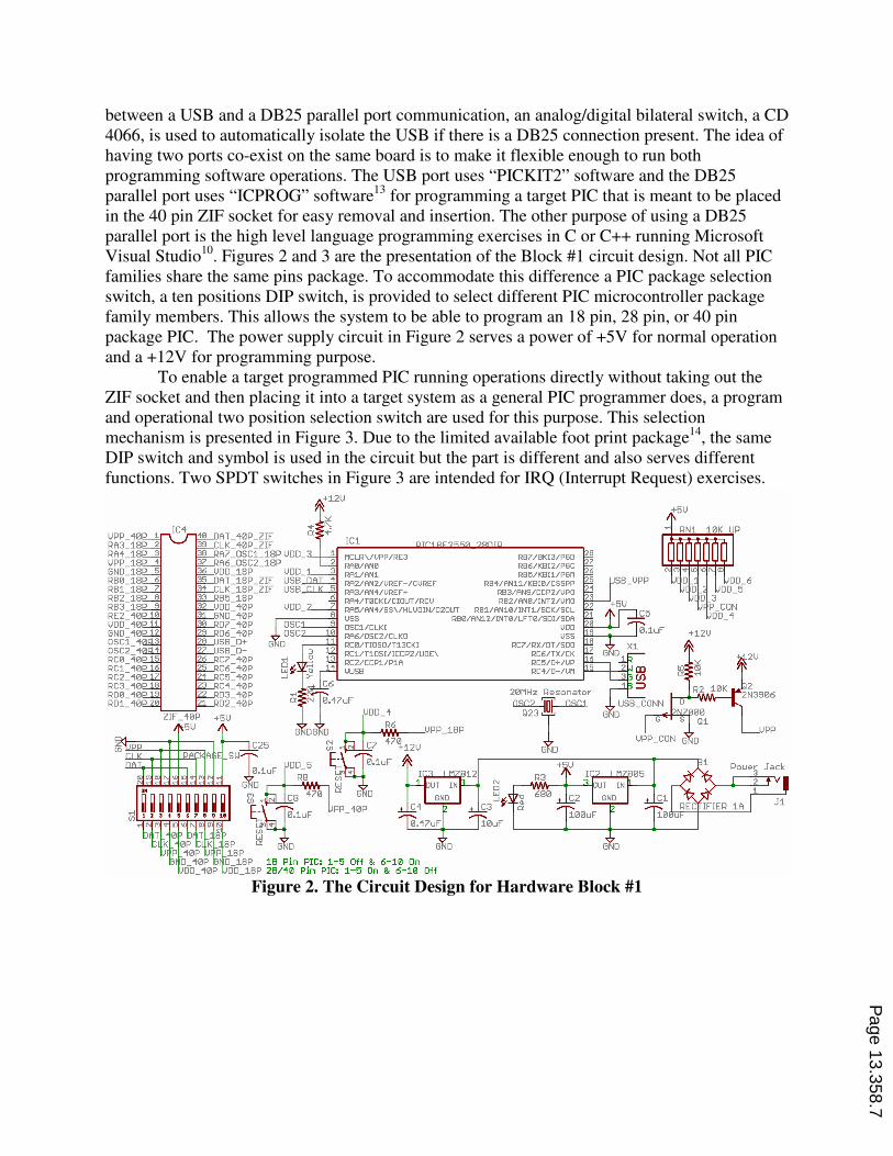
between a USB and a DB25 parallel port communication, an analog/digital bilateral switch, a CD 4066, is used to automatically isolate the USB if there is a DB25 connection present. The idea of having two ports co-exist on the same board is to make it flexible enough to run both programming software operations. The USB port uses “PICKIT2” software and the DB25 parallel port uses “ICPROG” software13 for programming a target PIC that is meant to be placed in the 40 pin ZIF socket for easy removal and insertion. The other purpose of using a DB25 parallel port is the high level language programming exercises in C or C++ running Microsoft Visual Studio10. Figures 2 and 3 are the presentation of the Block #1 circuit design. Not all PIC families share the same pins package. To accommodate this difference a PIC package selection switch, a ten positions DIP switch, is provided to select different PIC microcontroller package family members. This allows the system to be able to program an 18 pin, 28 pin, or 40 pin package PIC. The power supply circuit in Figure 2 serves a power of +5V for normal operation and a +12V for programming purpose. To enable a target programmed PIC running operations directly without taking out the ZIF socket and then placing it into a target system as a general PIC programmer does, a program and operational two position selection switch are used for this purpose. This selection mechanism is presented in Figure 3. Due to the limited available foot print package14, the same DIP switch and symbol is used in the circuit but the part is different and also serves different functions. Two SPDT switches in Figure 3 are intended for IRQ (Interrupt Request) exercises.
Figure 2. The Circuit Design for Hardware Block #1
Page 13.358.7
~ +12U
IC1
MCLR\/VPP/RE3 RB7/BKI3/PGD RA0/AN0 R86/K8l2/PGC RA1/AN1 R85/K8l1/PGM RA2/AN2/VREF-/CVREF RB1/AN11/K8l0/CSSPP RA3/AN1/VREF+ RB3/AN9/CCP2/VPO RA'\/T0CKI/CIOUT /RCV R82/AN8/INT2/VMO RA5/AN1/SS\/HLVDIN/C20UT RB1/AN10/INT1/SCK/SCL VSS RB0/AN12/INT0/LFT0/SDI/SDA OSC1/CLKI VD□ RA6/0SC2/CLKO VSS RC0/TIOSO/T13CKI RC7 /RX/OT /SOD RC1/T10Sl/lCCP2/UOE\ RC6/TX/CK RC2/CCP1/P1A RC5/D+/VP UUSB RC4/D-/VM
G D
Pin PIC: 1-5 On & 6-10 Off
20MHz Resonator
osgJ3 ~II□~
G D
+5U
UPP
G D
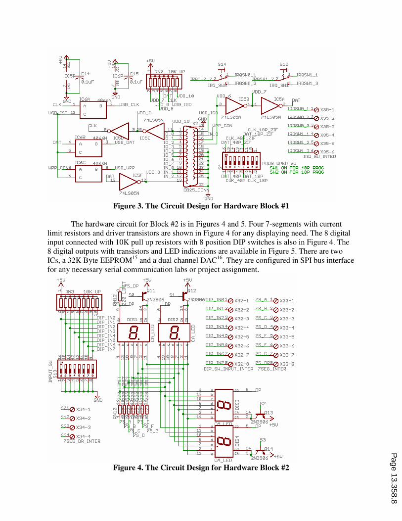
Figure 3. The Circuit Design for Hardware Block #1
The hardware circuit for Block #2 is in Figures 4 and 5. Four 7-segments with current limit resistors and driver transistors are shown in Figure 4 for any displaying need. The 8 digital input connected with 10K pull up resistors with 8 position DIP switches is also in Figure 4. The 8 digital outputs with transistors and LED indications are available in Figure 5. There are two ICs, a 32K Byte EEPROM15 and a dual channel DAC16. They are configured in SPI bus interface for any necessary serial communication labs or project assignment.
Figure 4. The Circuit Design for Hardware Block #2
Page 13.358.8
~~ ~~ +5U
"J:5~ 1 'I ·;~6P..k15
,11 l '"' p ·'"' N
~ ~.,.,6A-'---""""PNG D
::t (J)
I
CLK 1 R 2 SB_CLK
+5U
1-(') ::J..-, ~00-,.,.,.,..,..,.,,....,.,..,.,,,. ..
S0!Q) X3'1- 1
51.lQ) X3'1-2
5n0 X3"1-3
53.1e) X3"1-"I 7SEG_DR_INTER
+5U
D w _j
I <I: u
..-<M cs,a, ..-<..-<
S1'1 S15
~ RQSW0_~ RQSW1_1
+5U
D w _j
I <I: u
I\.N..-< ..-<
IRQ_sw@---IRQSW0_3 IRQ_swP--IRQSW1_3
IN0 10 X32-1
DIP INl 20 X32-2
DIP IN2 30 X32-3
DIP IN3 '10 X32-'I
DIP IN4 50 X32-5
DIP IN5 60 X32- 6
OTP TN6 70 X32-7
---1- 10 X35-1 7'1LS05N IRQ$W0 2 20 X35-2
TRQSW0 3 30 X35-3
TRQSW1 1 "'0 X35-'I
TRQSW1 2 50 X35-5
TRQSW1 3 60') X35-6 IRQ_§w_INTER
PROG_OPER_SW SW1 ON FOR '10P PRDG SW2 ON FOR 18P PRDG
~ X33-1
~ X33-2
~ X3 3-3
~ X33-"I
Z$_L...5Q) X33-5
~ X3 3- 6
z.s.JL.Ze) X33-7
OTP TNZ 8 0 X32-8 ~ X33-8 DIP _SW_!NPUT _INTER 7SEG_INTER

Figure 5. The Circuit Design for Hardware Block #2
The circuit design for hardware Block #3 has a RS232 conversion IC17 to be used for any TTL to RS232 standard signal conversion and a four channels general purpose OPAmp for any signal conditional design that needs OPAmp assistance. A jumper selection of source voltage of +5V or +12V is used for different OPAmp operation requirements. A separate 20M Hz resonator is added for those PIC family members such as the PIC 16F84A4 and PIC 16F877A6 that do not have any internal oscillator for the needed instruction clock signal. These are presented in Figure 6.
Figure 6. The Circuit Design for Hardware Block #3
The Block #4 are various breakable single line10 pin female sockets to be used as interface jumper wire connections for different needed signals between peripheral circuits, components, and target PIC microcontroller. These include a LCD module, 3*4 matrix keypad, 8
Page 13.358.9
LIT_0
(') D w ....J
ICS
C1+ U+
C1-u-
C2+
C2-
HIN HOUT T2IN T20UT R1DUT R1IN R2DUT R2IN
RX□
20MHz Resonator OSC2~ C1_CON
Q24 I OPAmp
G D
LIT _1
..,.. ll) D D w w ....J ....J
LIT CS)
(1) D
.-i D
w w ....J ....J
D
cs C11 ~ 5U
l 0.iuF
.iuF+ '"'
'-~□ T"M t S_RXD ~
TTL_ TX□ G D
OR
~ °' +' '' - .,.I 116 OR
PW: +5U Jumper 1 8' 2~ +12U Jumper on 2 8' :'.l, 0.1uFoR
G D
+5U
I-IP\
CS\ SI 2 DI SCK HOLD
0.1uF
+5U GND
1 voo VOUTl'I B UTA
!CS t'IVSS 7
s SCK VOUTB
SOI !LOAC
GND
PA0_OUT
PA1_OUT
PA2_OUT
PA3_OUT

bit IOs, SPI, RS232, 20MHz resonator, and associate pull up resistors. They are placed around a 2.2”*6.5” bread board for user’s easy access of needed interface connections. The high power section of the hardware, Block #5, is present in Figures 7 and 8. To eliminate any possible noise contamination while running high power stepper or DC motors controls, an 8 channel optical isolator is implemented in the design. Eight IRF530 power FETs are the drivers for those high power needs. Separate terminal block type connectors are used for small gauge wire connections for different high power exercises. Different connections found in the circuits’ designs allow for the control of On-Off exercises by using associated IO_X input signal. The current direction manipulations through H-bridge configurations are presented in Figure 8. There are associated LEDs to indicate different current direction flow for students’ easy observation and trouble shooting.
Figure 7. The Circuit Design for Hardware Block #5
Figure 8. The Circuit Design for Hardware Block #5.
The circuits for Block #6 are presented in Figures 9 and 10. The 8 channel hardware debounced I/O signals that can be used for needed microcontroller exercises or any standard digital course implementations. This makes the training system flexible enough to cover traditional digital logic experimentations if desired. Due to the PCB space limitation, the SD memory interface was not implemented in this current design.
Page 13.358.10
ID
ucc J T_0
ucc
F530 ~ CCDN_ UT _0_
ucc J T_4
ID
~ F530
CCDN_ UT_4_
ucc J T_6 I
ucc J T_7 G
F530 F530 ~ CCDN_ UT _6_ GND ~ 0
CCDN_ UT_7_
H Bridge 1 Conn: VCC to OUT _0 8. OUT _2 OUT_0_GNO 8. OUT_1 to HB1_1 OUT_2_GNO 8. OUT_3 to HB1_2 OUT_1_GNO 8. OUT_3_GND to GND HB1_1 ~ HB1_2 are Motor 1 Conn
R7 LED11
HB1 81_2
LED12 680
H Bridge 2 Conn: VCC to OUT_ 'I 8. OUT _6 OUT_'I_GNO 8. OUT_5 to HB2_1 OUT_6_GNO 8. OUT_7 to HB2_2 OUT_5_GNO 8. OUT_7_GNO to GNO HB2_1 ~ HB2_2 are Motor 2 Conn
R 0LE013
HB2 680 "" Yellow Green 82_2
'' R11 LEDH 680
J T_2
~ F530
CCDN_ UT_2_GND
J T_5
~ F530
CCDN_ UT_5_GND

Figure 9. The Circuit Design for Hardware Block #6
Figure 10. The Circuit Design for Hardware Block #6
V. Printed Circuit Board (PCB) Implementation
Based on the bill of materials from the designed circuits14, there are a total of 187 electronic components needed on the PCB. The goal is to make PCB that has to be less than a regular paper size of 8.5”*11” for easy transportation. When implementing the designed circuits into a desirable fit in a PCB, there are several factors that need to be considered: 1. All the parts should be used in a through-hole format; any surface mount component will
Page 13.358.11
IT_2
IC12C
8
C a, a,
~ IT_ 4 74ALS00N
IC13C
C a, a, ,._
(!)
1,
C a, a, ,._
(!)
1, 74ALS00N
DB $W0 1 0 X28-1 SW5
nR SW1 20 X28-2
nR SW? 3 0 X28-3
OR SW3 "0 X28-4
OR $W4 50 X28-5
OR $W5 60 X28-6
5U
IT 1
IT 3
C 3 IT 5
nR sw6 7 0 x2e-J·1 F
SW7 ns SLIZ 00 X28-B
OB_SWITCH_INTER
5U
..-i::l ,-I :,
..-i::l ,-I:,
IC12P C 4 IC13P
"-!i! ID
0.1 F "-'il
ID
G 0

make the assembly and trouble shooting very difficult. 2. Even if footprints and prices for the surface mount parts are lower, they do not justify the difficulty in replacing and updating the training system in the future. 3. Not all the available parts’ foot prints for the software can be perfectly matched with the
parts from available venders, so making customized foot prints is necessary. 4. Different adjustments on the parts’ footprint are a critical design process. 5. To better fit to the budget, an adjustment on parts’ footprints with available parts should
work coherently during the PCB layout designs. 6. Four layers PCB is a preferable choice and easy layout but the manufacturing cost has forced the design to be a double sided board. 7. The size of the training PCB can only shrink to its absolute minimum of 8”*10” to host a total of 187 electronic components. This makes the routing a very challenging task. The auto route function performed by the software definitely will not be able to do the job. Several trials and manual routes are the solution to meet the goal. 8. High power and low power sections of the circuits should be separated. 9. The routing traces of the high power signal should be wider for carrying higher current. 10. High frequency components, such as USB, resonators, and SPI bus lines, should be placed as close as possible to the communication partners. 11. All the interface connectors should be placed around the 2.2”*6.5” breadboard for easy
access in building interfaces. 12. All the low power, USB, DB25, and ribbon cable connections, are placed at one side of the PCB and all the high power connectors for motor controls are placed on the other side. These arrangements are designed for user friendly and easy access in performing lab experimentations. After applying these PCB designed considerations, a final assembled PCB for this PIC training system is presented in Picture 1.
Picture 1. The Assembled PIC Training System
Page 13.358.12
VI. Training System in Distance Learning
Currently, this newly developed PIC microcontroller training system is under field testing and evaluation at Blue Ridge Community College, VA, and Olympic College, WA. The intent is to use the teaching/learning system in distance learning classes. After the beta testing and refinements the system will be available to other interested institutions. The objective is to solve the cost, hands-on trouble shooting, and teaching/learning efficiency issues while doing laboratory activities with distance learning classes. To meet the objective, everyone needs to use the same platform (this training system). The issues with hardware interface and software source code design can be resolved quickly via groups’ discussion, on-line conference lecture, one on one video conference, and e-mail system. The unique feature of this training system is that it matches the curriculum objectives of the three institutions involved in this project. This approach differs from the existing product available in the market and can be adopted universally. The other advantage is that the cost of this system is below competition, because it is not for profit driven development, and its will provide a service to the improvement of the hands-on distance
learning applications.
VII. Conclusions and Suggestions
The immediate impact of this project is the developing of expertise of the project team members. Team members have realized the vast amount of work required to develop new training hardware and their instructional support materials. This is the best motivation when your team members want to fulfill goals and conduct research for solutions. It is a very demanding learning experience for everyone on this design team. There also are demands for this training system. This was determined from various conversations with different institution’s faculty during conference meetings. It is recognized and concerned that there is a common obstacle in implementing hands-on distance learning – a lack of a good teaching platform that is effective and affordable. During the design and development period of 13 months, there are different groups of the students at ODU, BRCC, and OC involved in assisting with testing circuits, assembling PCBs, organizing electronic components, evaluating/testing assembled PCBs, and completing instruments for evaluating the effectiveness of this training system. They all responded very positively during the learning experience while assisting with this project. The other issue for this project was the budget; there is always lack of funds to get the job done. Spending more time and paying attention to details will still enable you to reach the optimal goals without jeopardize the quality of the objectives in this project. For example the budget for this training system board is set to be around $100 and the bill of material calls14 for a total of $124.93. This does not include the assembling cost. This makes the budget over by more than 25%. But going through the extended search for the parts vendor and negotiating on the volume price purchase, the bill of material costs can be lowered by 15%-20%. Paying the students’ help in assembling and at the same time teaching them the manufacturing process and quality control and trouble shooting can lower the labor cost of the assembling of the training system. It also provides students with very practical training experiences for their future work places. These approaches make the $100/training system board a closer reality. The prime goal is to make affordable technology-related course materials, activities, hardware, and software to students who do not have access to microcontroller training that is
Page 13.358.13

required for many high-tech jobs. This project produced microcontroller prototype hardware and software and instructional materials needed to support the distance delivery of several microprocessor related courses. Without allowing students to actually build circuits and test their designed software programs on real hardware set-ups using a common platform, it is very hard to for them to understand the course content through distance learning programs.
As this project progressing, the individual laboratory activities are also being developed to reinforce student learning and skill development in programming concepts as well as providing a platform for individual student research and development after course completion. The expected outcomes will be better trained/educated students who will qualify for positions in the knowledge-based workforce. VIII. Bibliography
1. Michael, K. “The Effect of a Computer Simulation Activity versus a Hands-on Activity on Product
Creativity in Technology Education”. (2001). Journal of Industrial Teacher Education. Volume 13, Number 1. 2. Bernard, R.M., Abrami, P.C., Lou, U., Borokhovski, E., Wade, A.W., L. et al. (2004). How does distance education compare with classroom instruction? A meta-analysis of the empirical literature. Review of
Educational Research. 74(3), 379-439.
3. Gokhale, A. (2007). Effectiveness of Computer Simulation for Enhancing Higher Order Thinking. Journal of
Industrial Teacher Education. Volume 33, Number 4. 4. PIC16F84A Data Sheet. (2004). Microchip Technology Inc. http://www.microchip.com/. 5. PIC16F88 Data Sheet. (2004). Microchip Technology Inc. http://www.microchip.com/. 6. PIC16F877A Data Sheet. (2004). Microchip Technology Inc. http://www.microchip.com/. 7. PIC16F87/88 Flash Memory Programming Specification (2002). Microchip Technology Inc., DS39607B.
8. PIC16F87X EEPROM Memory Programming Specification (2003). Microchip Technology Inc., DS39025F.
9. PIC16F8X EEPROM Memory Programming Specification 2003). Microchip Technology Inc., DS30262E.7. 10. Hsiung, Steve, Ward, Dave. (2006). Design Software and Hardware for PC I/O Control. Journal of
Engineering Technology. Pages 16-24. Spring 2006. 11. On-Chip Debugger Specification. (2001). Microchip Technology Inc., DS51242A.
12. PICKIT2. (2007). Available: http://www.microchip.com/pickit2, December, 2007. 13. ICPROG. (2007). Available: http://www.ic-prog.com/index1.htm, December, 2007.
14. Eagle. (2004). Easy Applicable Graphical Layout Editor, 2nd Edition, Cadsoft Inc.
15. 25AA256/45LC256 Data Sheet. (2007). Microchip Technology Inc. DS21822F. http://www.microchip.com/.
16. MCP4821/MCP4822 Data Sheet. (2005). Microchip Technology Inc. DS21953A. http://www.microchip.com/. 17. MAX232-MAX249 Data Sheet. (2006). Maxim Integrated Products. http:///www.maxim-ic.com/.
Page 13.358.14