Embed Size (px)
Citation preview

Design alternatives for barrel shifters
Matthew R. Pillmeier
Rushmore Processor 2
Unisys Corporation
Blue Bell, PA 19424
Michael J. Schulte and E. George Walters III
Computer Architecture and Arithmetic Laboratory
Computer Science and Engineering Department
Lehigh University
Bethlehem, PA 18015, USA
ABSTRACT
Barrel shifters are often utilized by embedded digital signal processors and general-purpose processors to ma-nipulate data. This paper examines design alternatives for barrel shifters that perform the following functions:shift right logical, shift right arithmetic, rotate right, shift left logical, shift left arithmetic, and rotate left. Fourdi�erent barrel shifter designs are presented and compared in terms of area and delay for a variety of operandsizes. This paper also examines techniques for detecting results that over ow and results of zero in parallelwith the shift or rotate operation. Several Java programs are developed to generate structural VHDL modelsfor each of the barrel shifters. Synthesis results show that data-reversal barrel shifters have less area and mask-based data-reversal barrel shifters have less delay than other designs. Mask-based data-reversal barrel shiftersare especially attractive when over ow and zero detection is also required, since the detection is performed inparallel with the shift or rotate operation.
Keywords: barrel shifters, rotators, masks, data-reversal, over ow detection, zero ag, computer arithmetic.
1. INTRODUCTION
Shifting and rotating data is required in several applications including arithmetic operations, variable-lengthcoding, and bit-indexing. Consequently, barrel shifters, which are capable of shifting or rotating data in a singlecycle, are commonly found in both digital signal processors and general-purpose processors. Several patents [1{10] and research articles [11{15] have been written on e�cient designs and implementations for barrel shifters.In [16], several 32-bit barrel shifters are compared in terms of delay, power, and power-delay product.
This paper examines design alternatives for barrel shifters that perform the following operations: shift rightlogical, shift right arithmetic, rotate right, shift left logical, shift left arithmetic, and rotate left. These designsare optimized to share hardware for di�erent operations. Techniques are also presented for detecting resultsthat over ow and results of zero in parallel with the shift or rotate operation. Section 2 describes the basicshift and rotate operations and gives examples of each operation. Section 3 presents designs for several typesof barrel shifters. Section 4 gives area and delay estimates for each type of barrel shifter as the operand sizevaries. Section 5 presents conclusions. Further details on the designs presented in this paper are given in [17].
2. SHIFT AND ROTATE OPERATIONS
In this paper, we de�ne A to be the input operand, B to be the shift/rotate amount, and Y to be theshifted/rotated result. We de�ne A to be an n-bit value, where n is an integer power of two. Therefore,B is a log2(n)-bit integer representing values from 0 to n � 1. The barrel shifters presented in this paperperform the following six operations: shift right logical, shift right arithmetic, rotate right, shift left logical,shift left arithmetic, and rotate left. Table 1 gives an example for each of these operations. In this table, thebit vector for A is denoted as a7a6a5a4a3a2a1a0 and the shift/rotate amount, B, is 3 bits. As illustrated in thistable:
Operation Y
3-bit shift right logical 0 0 0 a7a6a5a4a33-bit shift right arithmetic a7a7a7a7a6a5a4a33-bit rotate right a2a1a0a7a6a5a4a33-bit shift left logical a4a3a2a1a0 0 0 0
3-bit shift left arithmetic a7a3a2a1a0 0 0 0
3-bit rotate left a4a3a2a1a0a7a6a5
Table 1. Shift and rotate examples for A = a7a6a5a4a3a2a1a0 and B = 3.
3-bit Opcodeleft rotate arithmetic Operation
0 0 0 shift right logical
0 0 1 shift right arithmetic
0 1 X rotate right
1 0 0 shift left logical
1 0 1 shift left arithmetic
1 1 X rotate left
Table 2. Operation control bits.
� A B-bit shift right logical operation performs a B-bit right shift and sets the upper B bits of the resultto zeros.
� A B-bit shift right arithmetic operation performs a B-bit right shift and sets the upper B bits of theresult to an�1, which corresponds to the sign bit of A.
� A B-bit rotate right operation performs a B-bit right shift and sets the upper B bits of the result to thelower B bits of A.
� A B-bit shift left logical operation performs a B-bit left shift and sets the lower B bits of the result tozeros.
� A B-bit shift left arithmetic operation performs a B-bit left shift and sets the lower B bits of the resultto zeros. The sign bit of the result is set to an�1.
� A B-bit rotate left operation performs a B-bit left shift and sets the lower B bits of the result to theupper B bits of A.
3. BARREL SHIFTER DESIGNS
This section discusses barrel shifter designs. Basic shifter and rotator designs are described �rst in Section 3.1.Mux-based data-reversal barrel shifters, mask-based data-reversal barrel shifters, mask-based two's complementbarrel shifters, and mask-based one's complement barrel shifters are then discussed in Sections 3.2 through 3.5.In the following discussion the term multiplexor refers to a 1-bit 2-to-1 multiplexor, unless otherwise stated.The operation performed by the barrel shifters is controlled by a 3-bit opcode, which consists of the bits left,rotate, and arithmetic, as summarized in Table 2. Additional control signals, sra and sla, are set to one whenperforming shift right arithmetic and shift left arithmetic operations, respectively.
3.1. Shifters and Rotators
An n-bit logarithmic barrel shifter uses log2(n) stages [1, 2]. Each bit of the shift amount, B, controls a di�erent
stage of the shifter. The data into the stage controlled by bk is shifted by 2k bits if bk = 1; otherwise it is not
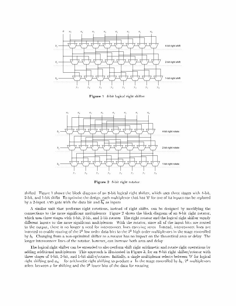
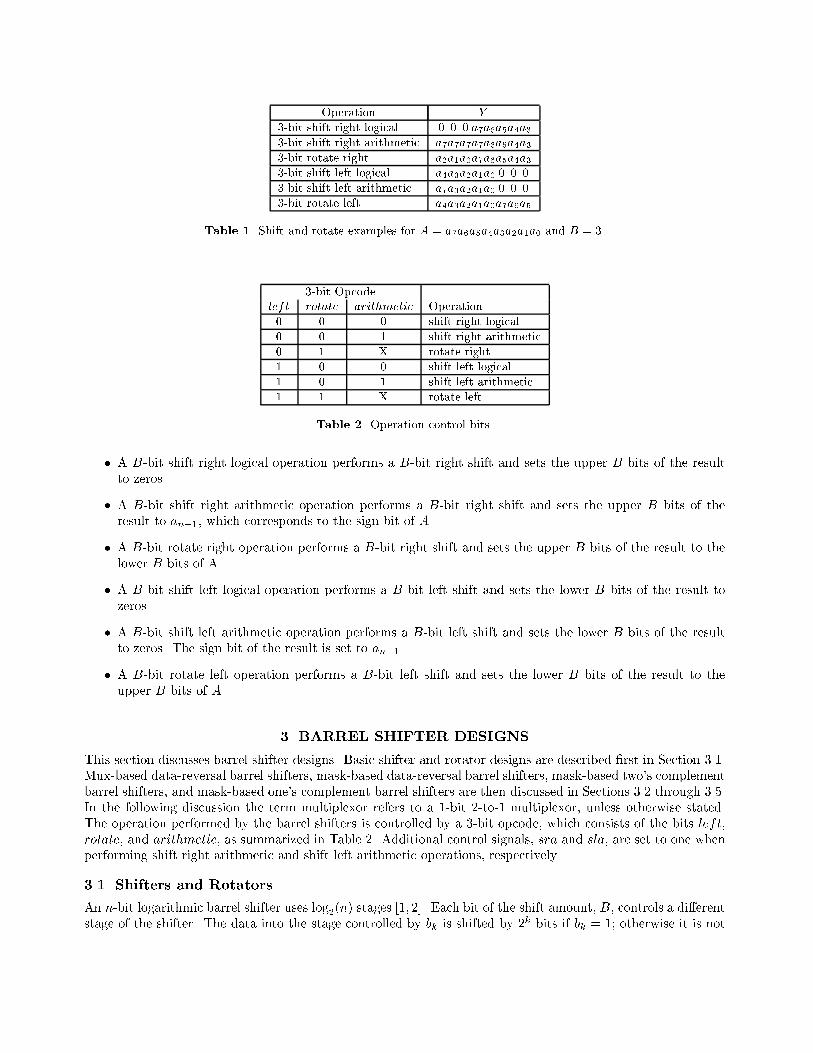
Figure 1. 8-bit logical right shifter.
Figure 2. 8-bit right rotator.
shifted. Figure 1 shows the block diagram of an 8-bit logical right shifter, which uses three stages with 4-bit,2-bit, and 1-bit shifts. To optimize the design, each multiplexor that has '0' for one of its inputs can be replacedby a 2-input and gate with the data bit and bk as inputs.
A similar unit that performs right rotations, instead of right shifts, can be designed by modifying theconnections to the more signi�cant multiplexors. Figure 2 shows the block diagram of an 8-bit right rotator,which uses three stages with 4-bit, 2-bit, and 1-bit rotates. The right rotator and the logical right shifter supplydi�erent inputs to the more signi�cant multiplexors. With the rotator, since all of the input bits are routedto the output, there is no longer a need for interconnect lines carrying zeros. Instead, interconnect lines areinserted to enable routing of the 2k low order data bits to the 2k high order multiplexors in the stage controlledby bk. Changing from a non-optimized shifter to a rotator has no impact on the theoretical area or delay. Thelonger interconnect lines of the rotator, however, can increase both area and delay.
The logical right shifter can be extended to also perform shift right arithmetic and rotate right operations byadding additional multiplexors. This approach is illustrated in Figure 3, for an 8-bit right shifter/rotator withthree stages of 4-bit, 2-bit, and 1-bit shifts/rotates. Initially, a single multiplexor selects between '0' for logicalright shifting and an�1 for arithmetic right shifting to produce s. In the stage controlled by bk, 2
k multiplexorsselect between s for shifting and the 2k lower bits of the data for rotating.
Figure 3. 8-bit mux-based right shifter/rotator.
A right shifter can be extended to also perform left shift operations by adding a row of n multiplexors bothbefore and after the right shifter [4]. When a left shift operation is performed, these multiplexors reverse thedata into and out of the right shifter. When a right shift operation is performed, the data into and out of theshifter is not changed. An 8-bit data-reversal logical shifter is shown in Figure 4.
3.2. Mux-based Data-Reversal Barrel Shifters
The techniques described previously can be combined to form a barrel shifter that performs shift right logical,shift right arithmetic, rotate right, shift left logical, shift left arithmetic, and rotate left. This approach is shownin Figure 5. Initially, a row of n multiplexors reverses the order of the data when left = 1 to produce A. Then,an n-bit right shifter/rotator performs the right shift or rotate operation on A to produce Y . Finally, a row ofn multiplexors reverses the data when left = 1 to produce the �nal result Y .
The design presented in Figure 5, called a mux-based data-reversal barrel shifter, also detects over ow andresults of zero. Over ow only occurs when performing a shift left arithmetic operation and one or more of theshifted-out bits di�er from the sign bit. A method for detecting over ow in parallel with the shift operation isshown in Figure 6. In each stage, the bits that are shifted out are xored with the sign bit; when no bits areshifted out, the sign-bit is xored with itself�. The outputs of the xor gates are then ored together to producethe over ow ag, which is '1' when over ow occurs. An additional multiplexor sets y0 to a0 when sla = 1. Thezero ag, which is '1' when Y is zero, is obtained from the logical nor of all of the bits in Y . One disadvantageof this mux-based data-reversal barrel shifter is that the zero ag is not computed until Y is produced.
3.3. Mask-based Data-Reversal Barrel Shifters
Another approach for designing barrel shifters with the same functionality as the one presented in Figure 5is to use a mask-based data-reversal approach [6]. With this approach, the primary unit that performs theoperations is a right rotator and the data-reversal technique is used to support left shift and rotate operations.In parallel with the data reversal and rotation, masks are computed that allow logical and arithmetic shiftingto also be performed. With the mask-based data-reversal approach, the over ow and zero ags are computed
�For shift left arithmetic, the sign-bit corresponds to a0, since the data is reversed.
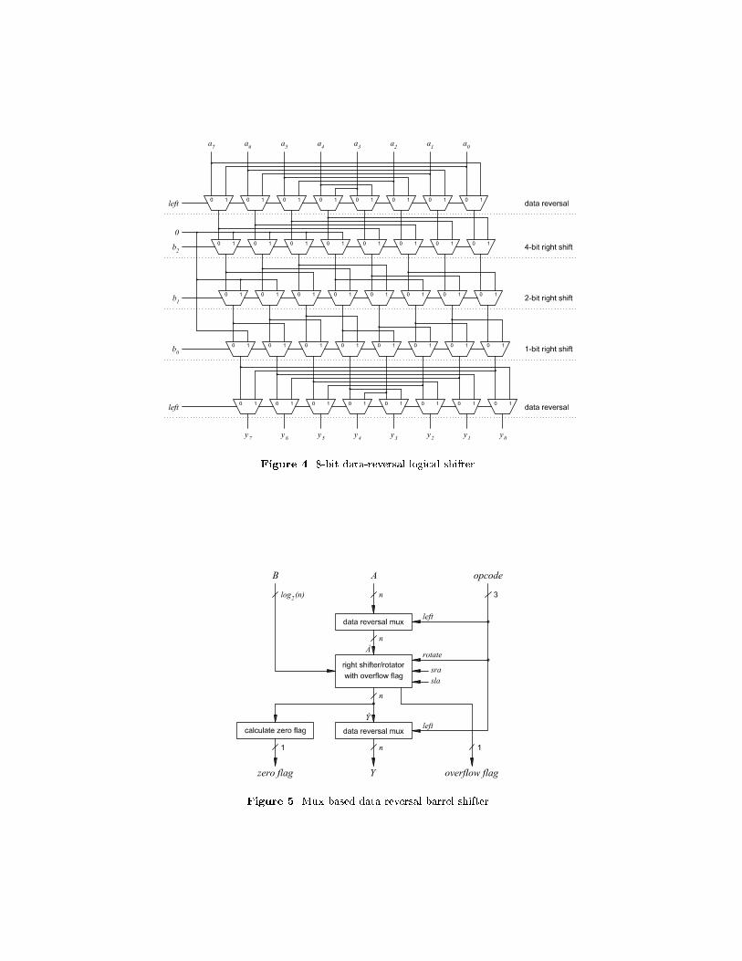
Figure 4. 8-bit data-reversal logical shifter.
Figure 5. Mux-based data-reversal barrel shifter.
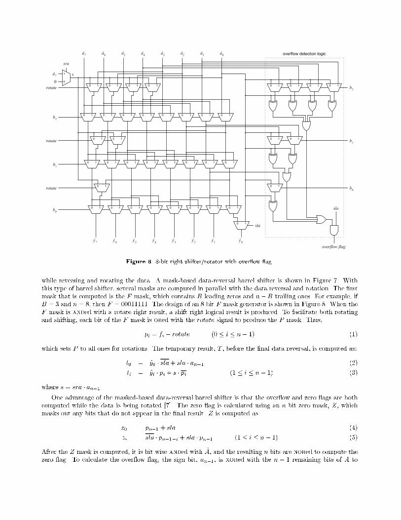
Figure 6. 8-bit right shifter/rotator with over ow ag.
while reversing and rotating the data. A mask-based data-reversal barrel shifter is shown in Figure 7. Withthis type of barrel shifter, several masks are computed in parallel with the data reversal and rotation. The �rstmask that is computed is the F mask, which contains B leading zeros and n�B trailing ones. For example, ifB = 3 and n = 8, then F = 00011111. The design of an 8-bit F mask generator is shown in Figure 8. When theF mask is anded with a rotate right result, a shift right logical result is produced. To facilitate both rotatingand shifting, each bit of the F mask is ored with the rotate signal to produce the P mask. Thus,
pi = fi + rotate (0 � i � n� 1) (1)
which sets P to all ones for rotations. The temporary result, T , before the �nal data reversal, is computed as:
t0 = y0 � sla+ sla � an�1 (2)
ti = yi � pi + s � pi (1 � i � n� 1) (3)
where s = sra � an�1.
One advantage of the masked-based data-reversal barrel shifter is that the over ow and zero ags are bothcomputed while the data is being rotated [7]. The zero ag is calculated using an n-bit zero mask, Z, whichmasks out any bits that do not appear in the �nal result. Z is computed as
z0 = pn�1 + sla (4)
zi = sla � pn�1�i + sla � pn�1 (1 � i � n� 1) (5)
After the Z mask is computed, it is bit-wise anded with A, and the resulting n bits are nored to compute thezero ag. To calculate the over ow ag, the sign bit, an�1, is xored with the n � 1 remaining bits of A to
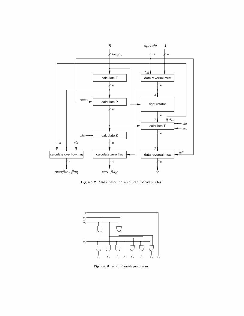
Figure 7. Mask-based data-reversal barrel shifter.
Figure 8. 8-bit F mask generator.
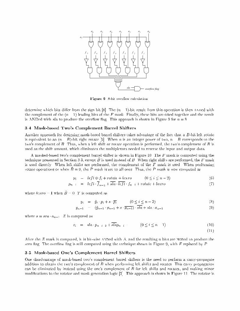
Figure 9. 8-bit over ow calculation.
determine which bits di�er from the sign bit [8]. The (n� 1)-bit result from this operation is then anded withthe complement of the (n� 1) leading bits of the F mask. Finally, these bits are ored together and the resultis ANDed with sla to produce the over ow ag. This approach is shown in Figure 9 for n = 8.
3.4. Mask-based Two's Complement Barrel Shifters
Another approach for designing mask-based barrel shifters takes advantage of the fact that a B-bit left rotateis equivalent to an (n�B)-bit right rotate [5]. When n is an integer power of two, n � B corresponds to thetwo's complement of B. Thus, when a left shift or rotate operation is performed, the two's complement of B isused as the shift amount, which eliminates the multiplexors needed to reverse the input and output data.
A masked-based two's complement barrel shifter is shown in Figure 10. The F mask is computed using thetechnique presented in Section 3.3, except B is used instead of B. When right shifts are performed, the F maskis used directly. When left shifts are performed, the complement of the F mask is used. When performingrotate operations or when B = 0, the P mask is set to all ones. Thus, the P mask is now computed as
pi = left� fi + rotate+ bzero (0 � i � n� 2) (6)
pn�1 = left � fn�1 + sla � left � fn�1 + rotate+ bzero (7)
where bzero = 1 when B = 0. Y is computed as
yi = yi � pi + s � pi (0 � i � n� 2) (8)
yn�1 = (yn�1 � pn�1 + s � pn�1) � sla+ sla � an�1 (9)
where s = sra � an�1. Z is computed as
zi = sla � pn�i�2 + slapn�i�1 (0 � i � n� 1) (10)
(11)
After the Z mask is computed, it is bit-wise anded with A, and the resulting n bits are nored to produce thezero ag. The over ow ag is still computed using the technique shown in Figure 9, with F replaced by P .
3.5. Mask-based One's Complement Barrel Shifters
One disadvantage of mask-based two's complement barrel shifters is the need to perform a carry-propagateaddition to obtain the two's complement of B when performing left shifts and rotates. This carry propagationcan be eliminated by instead using the one's complement of B for left shifts and rotates, and making minormodi�cations to the rotator and mask generation logic [3]. This approach is shown in Figure 11. The rotator is
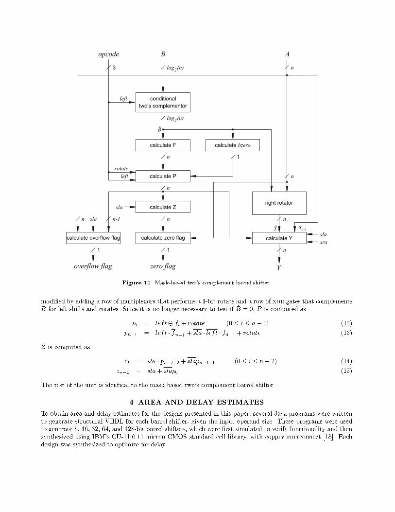
Figure 10. Mask-based two's complement barrel shifter.
modi�ed by adding a row of multiplexors that performs a 1-bit rotate and a row of xor gates that complementsB for left shifts and rotates. Since it is no longer necessary to test if B = 0, P is computed as
pi = left� fi + rotate (0 � i � n� 1) (12)
pn�1 = left � fn�1
+ sla � left � fn�1 + rotate (13)
Z is computed as
zi = sla � pn�i�2 + slapn�i�1 (0 � i � n� 2) (14)
zn�1 = sla+ slap0 (15)
The rest of the unit is identical to the mask-based two's complement barrel shifter.
4. AREA AND DELAY ESTIMATES
To obtain area and delay estimates for the designs presented in this paper, several Java programs were writtento generate structural VHDL for each barrel shifter, given the input operand size. These programs were usedto generate 8, 16, 32, 64, and 128-bit barrel shifters, which were �rst simulated to verify functionality and thensynthesized using IBM's CU-11 0.11 micron CMOS standard cell library, with copper interconnect [18]. Eachdesign was synthesized to optimize for delay.
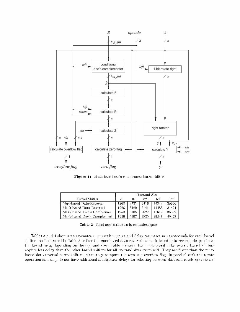
Figure 11. Mask-based one's complement barrel shifter.
Operand SizeBarrel Shifter 8 16 32 64 128
Mux-based Data-Reversal 1308 2731 6416 14242 30990Mask-based Data-Reversal 1226 3180 6141 14488 31424Mask-based Two's Complement 1958 3908 8827 17657 36592Mask-based One's Complement 1926 4507 9825 20247 40453
Table 3. Total area estimates in equivalent gates.
Tables 3 and 4 show area estimates in equivalent gates and delay estimates in nanoseconds for each barrelshifter. As illustrated in Table 3, either the mux-based data-reversal or mask-based data-reversal designs havethe lowest area, depending on the operand size. Table 4 shows that mask-based data-reversal barrel shiftersrequire less delay than the other barrel shifters for all operand sizes examined. They are faster than the mux-based data-reversal barrel shifters, since they compute the zero and over ow ags in parallel with the rotateoperation and they do not have additional multiplexor delays for selecting between shift and rotate operations.
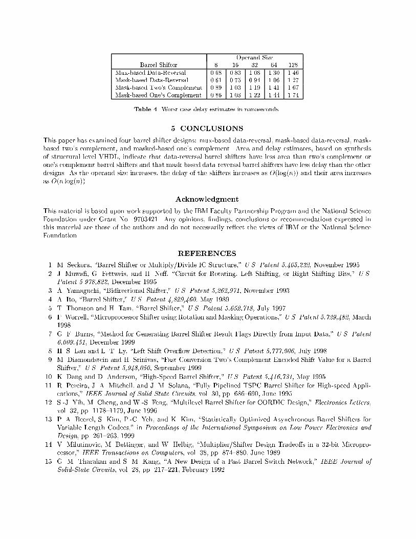
Operand SizeBarrel Shifter 8 16 32 64 128
Mux-based Data-Reversal 0.68 0.83 1.08 1.30 1.46Mask-based Data-Reversal 0.61 0.75 0.94 1.06 1.27Mask-based Two's Complement 0.89 1.03 1.19 1.41 1.67Mask-based One's Complement 0.86 1.08 1.22 1.44 1.74
Table 4. Worst case delay estimates in nanoseconds.
5. CONCLUSIONS
This paper has examined four barrel shifter designs: mux-based data-reversal, mask-based data-reversal, mask-based two's complement, and masked-based one's complement. Area and delay estimates, based on synthesisof structural level VHDL, indicate that data-reversal barrel shifters have less area than two's complement orone's complement barrel shifters and that mask-based data-reversal barrel shifters have less delay than the otherdesigns. As the operand size increases, the delay of the shifters increases as O(log(n)) and their area increasesas O(n log(n)).
Acknowledgment
This material is based upon work supported by the IBM Faculty Partnership Program and the National ScienceFoundation under Grant No. 9703421. Any opinions, �ndings, conclusions or recommendations expressed inthis material are those of the authors and do not necessarily re ect the views of IBM or the National ScienceFoundation.
REFERENCES
1. M. Seckora, \Barrel Shifter or Multiply/Divide IC Structure," U.S. Patent 5,465,222, November 1995.
2. J. Muwa�, G. Fettweis, and H. Ne�, \Circuit for Rotating, Left Shifting, or Right Shifting Bits," U.S.
Patent 5.978,822, December 1995.
3. A. Yamaguchi, \Bidirectional Shifter," U.S. Patent 5,262,971, November 1993.
4. A. Ito, \Barrel Shifter," U.S. Patent 4,829,460, May 1989.
5. T. Thomson and H. Tam, \Barrel Shifter," U.S. Patent 5,652,718, July 1997.
6. F. Worrell, \Microprocessor Shifter using Rotation andMasking Operations,"U.S. Patent 5,729,482, March1998.
7. G. F. Burns, \Method for Generating Barrel Shifter Result Flags Directly from Input Data," U.S. Patent
6,009,451, December 1999.
8. H. S. Lau and L. T. Ly, \Left Shift Over ow Detection," U.S. Patent 5,777,906, July 1998.
9. M. Diamondstein and H. Srinivas, \Fast Conversion Two's Complement Encoded Shift Value for a BarrelShifter," U.S. Patent 5,948,050, September 1999.
10. K. Dang and D. Anderson, \High-Speed Barrel Shifter," U.S. Patent 5,416,731, May 1995.
11. R. Pereira, J. A. Mitchell, and J. M. Solana, \Fully Pipelined TSPC Barrel Shifter for High-speed Appli-cations," IEEE Journal of Solid State Circuits, vol. 30, pp. 686{690, June 1995.
12. S.-J. Yih, M. Cheng, and W.-S. Feng, \Multilevel Barrel Shifter for CORDIC Design," Electronics Letters,vol. 32, pp. 1178{1179, June 1996.
13. P. A. Beerel, S. Kim, P.-C. Yeh, and K. Kim, \Statistically Optimized Asynchronous Barrel Shifters forVariable Length Codecs," in Proceedings of the International Symposium on Low Power Electronics and
Design, pp. 261{263, 1999.
14. V. Milutinovic, M. Bettinger, and W. Helbig, \Multiplier/Shifter Design Tradeo�s in a 32-bit Micropro-cessor," IEEE Transactions on Computers, vol. 38, pp. 874{880, June 1989.
15. G. M. Tharakan and S. M. Kang, \A New Design of a Fast Barrel Switch Network," IEEE Journal of
Solid-State Circuits, vol. 28, pp. 217{221, February 1992.

16. K. P. Acken, M. J. Irwin, and R. M. Owens, \Power Comparisons for Barrel Shifters," in Proceedings of
the International Symposium on Low Power Electronics and Design, pp. 209{212, 1996.
17. M. R. Pillmeier, \Barrel Shifter Design, Optimization, and Analysis," Master's thesis, Lehigh University,January 2002.
18. IBM, Blue Logic Cu-11 ASIC, June 2002. Available from http://www-3.ibm.com/chips/products/asics/products/cu-11.html.