Embed Size (px)
Citation preview

BARRELSHIFTER
1PRAGATISACHAN,2ANCHALKATIYAR,3ANITADIDAL,4PALLAVIGAUTAM
M.TechScholar,VLSI,JayotiVidyapeethWomen’sUniversityJaipur,Rajasthan,INDIA,E‐mail:[email protected],[email protected],[email protected],[email protected]
ABSTRACT
Barrelshiftersareoftenutilizedbyembeddeddigitalsignalprocessorsandgeneral‐purposeprocessorstomanipulatedata.Thisexaminesdesignalternativesforbarrelshiftersthatperformthefollowingfunctions:
Shiftrightlogical,shiftrightarithmetic,rotateright,shiftleftlogical,shiftleftarithmetic,androtateleft.Fourdifferentbarrelshifterdesignsarepresentedand compared in termsofareaanddelay fora varietyofoperand sizes.Thisalso examinestechniquesfordetectingresultsthatoverflowandresultsofzeroinparallelwiththeshiftorrotateoperation.
1. INTRODUCTION
A barrel shifter is a digital circuit that can shift a datawordbyaspecifiednumbersofbitsinoneclockcycle.Itcan be implemented as a sequence of multiplexors(mux),andinsuchanimplementationtheoutputofonemuxisconnectedtothenextmuxinawaythatdependsontheshiftdistance.Barrelshiftersareoftenutilizedbyembeddeddigitalsignalprocessorsandgeneralpurposeprocessorstomanipulatedata.Shiftingandrotatingdatais required in several applications, variable‐lengthcoding, and bit indexing. The mux based barrel shifterarchitecture are designed using 4:1,8:1,16:1,32:1,and64:1muxtrees.Eachmuxtreeisdesignedusing2:1mux.The power consumed bymux trees is quite significantandcannotbeignored.Thusitisimportanttominimizepower dissipation of mux trees within low powerdesigns.Multiplexersaredigitalcircuitthatgeneratesanoutput that exactly reflects state of one of a number ofdatainputs,basedonvalueofselectlines.Amultiplexerwithtwodatainputandoneselectlineisreferredas“2‐to‐1or 2:1”multiplexer. A barrel shifter primarily offersfiveoperations;rotateright,rotateleft,shiftrightlogical,shift left logical, and shift right arithmetic, shift leftarithmetic.Ann‐bit logarithmicbarrel shifteruses log2(n)stages[1,2].Eachbitoftheshiftamount,B,controlsa different stage of the shifter. The data in to stagecontrolledbybkisshiftedby2kbitsifbk=1;otherwiseitis not shifted. Techniques are also presented fordetecting results that overflow and results of zero inparallelwiththeshiftorrotateoperation.
2. DESIGNSPECIFICATION
Basic shifter and rotator designs are described firstfollowedbyMux‐baseddata‐reversalbarrel‐shifters.Thetermmultiplexer refers to a 1‐bit to 2‐to‐1multiplexorunlessotherwisestated.Arowofnmultiplexorsreversethe order of the data when left=1 to produce the finalresult. A Mux based data reversal barrel shifter, alsodetectoverflowandresultsofzero.Overflowonlyoccurswhen performing a shift left arithmetic operation andoneormoreof the shifted‐out bits differ from the signbit. The operation performed by the barrel shifters iscontrolled by a 3‐bit opcode,which consists of the bitsleft, rotateandarithmetic, additional control signal, sraand sla are set to one when performing shift right
arithmetic and shift left arithmetic operations. An n‐bitlogarithmicbarrelshifteruseslog2(n)stages[1,2].Eachbitoftheshiftamount,B,controlsadifferentstageoftheshifter.Thedataintostagecontrolledbybkisshiftedby2kbitsifbk=1;otherwiseitisnotshifted.Techniquesarealso presented for detecting results that overflow andresults of zero in parallel with the shift or rotateoperation.
Tableno.‐1:ShiftandrotateexampleforA=a7a6a5a4a3a2a1a0andB=3
Operation Y
3‐bitshiftrightlogical 000a7a6a5a4a3
3‐bitshiftrightarithmetic a7a7a7a7a6a5a4a3
3‐bitrotateright a2a1a0a7a6a5a4a3
3‐bitshiftleftlogical a4a3a2a1a0000
3‐bitshiftleftarithmetic a7a3a2a1a0000
3‐bitrotateleft a4a3a2a1a0a7a6a5
3. DESIGNMETHODOLOGIES
Tools:‐Modelsim
BlockDiagram:‐
PRAGATI SACHAN et al. DATE OF PUBLICATION: SEP 23, 2014
ISSN: 2348-4098 VOLUME 2 ISSUE 7 SEP-OCT 2014
INTERNATIONAL JOURNAL OF SCIENCE, ENGIEERING AND TECHNOLOGY- www.ijset.in 1434

TheblockdiagramshowingtheDatain,direction, inputreversal,shiftorrotate,selectline,outputreversal,dataout.
TableNO.–2:BarrelShifterFunctionality
Mode Rotation Direction Description
ShiftLeftLogical
0 0 Logicshiftleft,0isshifted throughthe right most(lsb)bit.
RotateLeft
1 0 Left rotate, theright most bit isshifted back informtheright.
ShiftRightLogical
0 1 Logical shift right,0isshiftedtheleftmost(msb)bit.
RotateRight
1 1 Right rotate, theright most bit isback in from theleft.
The right rotator and the logical right shifter supplydifferent inputs to the more significant multiplexors.Withtherotator,sincealloftheinputbitsareroutedtothe output, there is no longer a need for interconnectlines carrying zeros. Instead, interconnect lines areinsertedtoenableroutingof the2k loworderdatabitstothe2khighordermultiplexorsinthestagecontrolledbybk.Changingfromanon‐optimizedshiftertoarotatorhas no impact on the theoretical area or delay. Thelonger interconnect lines of the rotator; however, canincreasebothareaanddelay.Thelogicalrightshiftercanbe extended to also perform shift right arithmetic androtate right operations by adding additionalmultiplexors.Thisforan8‐bitrightshifter/rotatorwiththree stages of 4‐bit, 2‐bit, and 1‐bit shifts/rotates.Initially, a single multiplexor selects between '0' forlogicalrightshiftingand1forarithmeticrightshiftingtoproduces.Inthestagecontrolledbybk,2kmultiplexorsselectbetweensforshiftingandthe2klowerbitsofthedataforrotating.Beforeandaftertherightshifter,whena left shift operation is performed, these multiplexorsreversethedataintoandoutoftherightshifter.Whenarightshiftoperationisperformed,thedataintoandoutoftheshifterisnotchanged.
Tableno3
3.1Operationcontrolbit
1. A B‐bit shift right logical operation performs a B‐bitrightshiftandsetstheupperBbitsoftheresulttozeros.
2.AB‐bitshiftrightarithmeticoperationperformsaB‐bit right shift and sets theupperBbits of the result toan‐1,whichcorrespondstothesignbitofA.
3. A B‐bit rotate right operation performs a B‐bit rightshiftandsetstheupperBbitsoftheresulttothelowerBbitsofA.
4.AB‐bitshiftleftlogicaloperationperformsaB‐bitleftshiftandsetsthelowerBbitsoftheresulttozeros.
5.AB‐bitshiftleftarithmeticoperationperformsaB‐bitleftshiftandsetsthelowerBbitsoftheresulttozeros.Thesignbitoftheresultissettoan‐1.
6.AB‐bitrotateleftoperationperformsaB‐bitleftshiftandsetsthelowerBbitsoftheresulttotheupperBbitsofA.
The operation performed by the barrel shifters iscontrolled by a 3‐bit opcode,which consists of the bitsleft, Rotate, and arithmetic, as summarized in Table 3.Additional control signals, sra and sla, are set to onewhen performing shift right arithmetic and shift leftarithmeticoperations,respectively.
4. DESIGNIMPLEMENTATION
Abarrelshifterisoftenimplementedasa:‐
RotateandShiftDirection:‐Thedirectionoftherotateand shift operation is implemented by reversing theinputandoutputvector,usingthismethodallowsfortheshiftorrotatelogictobekeptsimple.
[A]LogicalShiftOperation:‐Thelogicalshiftoperationinserts0valuesforeachshiftoperation.Theinputvectoris shifted in the selected direction according to thenumberofbitsintheselectindication.
[B]RotateOperation: ‐The rotateoperation is a shiftwhere thebitwhich is shiftedoutof the vectorMSB isinsertedatitsLSB.
[C]ShiftandRotateOperation: ‐Wedefined A to betheinputoperand,Btobetheshift/rotateamount,andY
PRAGATI SACHAN et al. DATE OF PUBLICATION: SEP 23, 2014
ISSN: 2348-4098 VOLUME 2 ISSUE 7 SEP-OCT 2014
INTERNATIONAL JOURNAL OF SCIENCE, ENGIEERING AND TECHNOLOGY- www.ijset.in 1435
tobetheshifted/rotatedresult.WedefineAtobeann‐bitvalue,wherenisanintegerpoweroftwo.Therefore,Bisalog2(n)‐bitintegerrepresentingvaluesfrom0ton‐ 1 we define A to be the input operand, B to be theshift/rotate amount, and Y to be the shifted/rotated
result.We define A to be an n‐bit value,where n is aninteger power of two. Therefore, B is a log2(n)‐bitintegerrepresentingvaluesfrom0ton‐1.
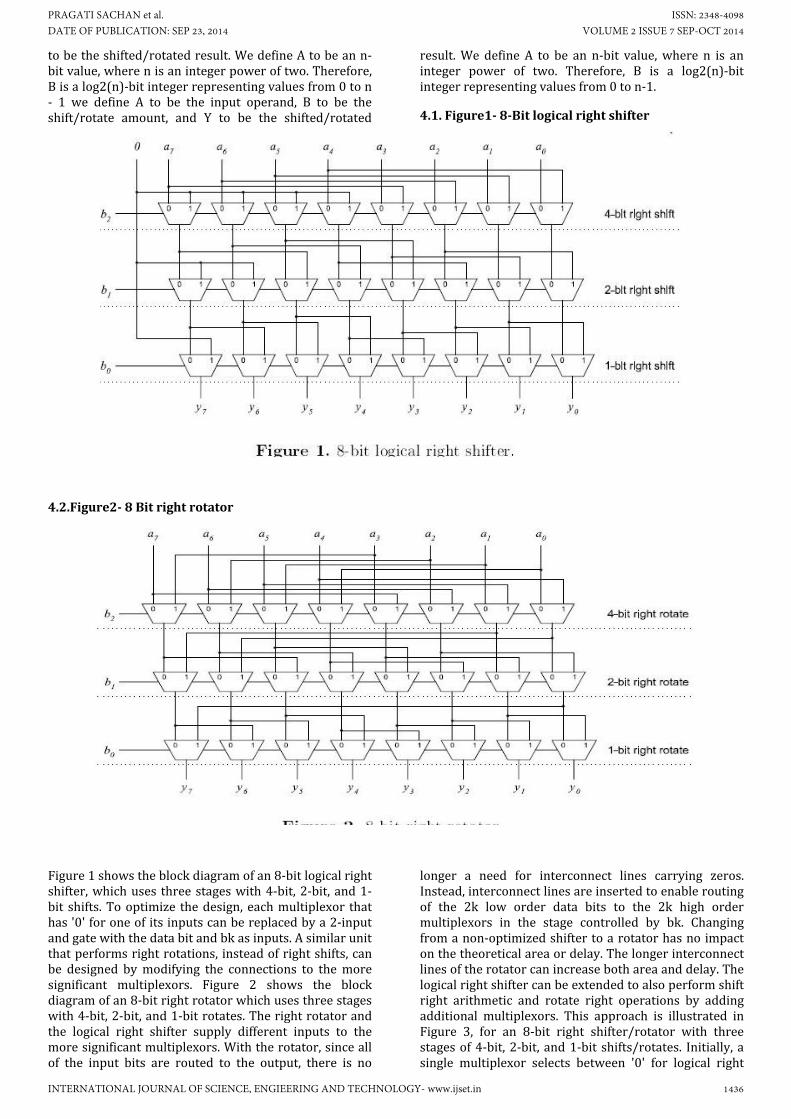
4.1.Figure1‐8‐Bitlogicalrightshifter
4.2.Figure2‐8Bitrightrotator
Figure1showstheblockdiagramofan8‐bitlogicalrightshifter,whichuses threestageswith4‐bit,2‐bit,and1‐bit shifts.Tooptimize thedesign,eachmultiplexor thathas'0'foroneofitsinputscanbereplacedbya2‐inputandgatewiththedatabitandbkasinputs.Asimilarunitthatperformsrightrotations, insteadofrightshifts,canbe designed bymodifying the connections to themoresignificant multiplexors. Figure 2 shows the blockdiagramofan8‐bitrightrotatorwhichusesthreestageswith4‐bit,2‐bit,and1‐bitrotates.Therightrotatorandthe logical right shifter supply different inputs to themoresignificantmultiplexors.Withtherotator,sinceallof the input bits are routed to the output, there is no
longer a need for interconnect lines carrying zeros.Instead,interconnectlinesareinsertedtoenableroutingof the 2k low order data bits to the 2k high ordermultiplexors in the stage controlled by bk. Changingfromanon‐optimizedshiftertoarotatorhasnoimpactonthetheoreticalareaordelay.Thelongerinterconnectlinesoftherotatorcanincreasebothareaanddelay.Thelogicalrightshiftercanbeextendedtoalsoperformshiftright arithmetic and rotate right operations by addingadditional multiplexors. This approach is illustrated inFigure 3, for an 8‐bit right shifter/rotator with threestagesof4‐bit,2‐bit,and1‐bit shifts/rotates. Initially,asingle multiplexor selects between '0' for logical right
PRAGATI SACHAN et al. DATE OF PUBLICATION: SEP 23, 2014
ISSN: 2348-4098 VOLUME 2 ISSUE 7 SEP-OCT 2014
INTERNATIONAL JOURNAL OF SCIENCE, ENGIEERING AND TECHNOLOGY- www.ijset.in 1436

shiftingandan‐1forarithmeticrightshiftingtoproduces. In the stage controlled by bk, 2kmultiplexors select
betweens forshiftingandthe2k lowerbitsof thedataforrotating.
4.3Figure3‐8Bitdatareversal
5. SIMULATIONANDRESULTS
5.1.SimulationResult(rightshift)
PRAGATI SACHAN et al. DATE OF PUBLICATION: SEP 23, 2014
ISSN: 2348-4098 VOLUME 2 ISSUE 7 SEP-OCT 2014
INTERNATIONAL JOURNAL OF SCIENCE, ENGIEERING AND TECHNOLOGY- www.ijset.in 1437

5.2.SimulationResult(leftshift)
5.3.SimulationResult(reversal)
5.4.SimulationResult(rotator)
PRAGATI SACHAN et al. DATE OF PUBLICATION: SEP 23, 2014
ISSN: 2348-4098 VOLUME 2 ISSUE 7 SEP-OCT 2014
INTERNATIONAL JOURNAL OF SCIENCE, ENGIEERING AND TECHNOLOGY- www.ijset.in 1438

5.5.SimulationResult(shift+rotateright)
5.6.SimulationResult(shifts+rotatesleft)
5.7.SimulationResult(barrelshifter)
PRAGATI SACHAN et al. DATE OF PUBLICATION: SEP 23, 2014
ISSN: 2348-4098 VOLUME 2 ISSUE 7 SEP-OCT 2014
INTERNATIONAL JOURNAL OF SCIENCE, ENGIEERING AND TECHNOLOGY- www.ijset.in 1439

6. FUTUREEXPECTS
The future expects of barrel shifter is that it minimizetheareaandpowerdelayof thecircuit.Areaanddelayestimates, based on synthesis of structural level VHDL,indicatethatdata‐reversalbarrelshiftershavelessareathan two's complement or one's complement barrelshifters and that mask‐based data‐reversal barrelshifters have less delay than the other designs. As theoperandsizeincreases,thedelayoftheshiftersincreasesasO(log(n))andtheirareaincreasesasO(nlog(n)).Intothe future expectation we attach a overflow detectionlogic,sothedatashouldnotbewaste.
7. CONCLUSION
This paper named “Barrel Shifter” undertook by thestudentofM.Tech(VERILARGESCALEINTEGERATION)THIRD SEMESTER under the guidance and support ofourteacher.
The reason behind undertaking this project simply lieswith the fact that there are somany circuits that havemorepowerconsumptionanddelay,sotominimizetheareaanddelayweareusingshiftingorrotation.Herewearedoingshiftrightlogical,shiftrightarithmetic,rotateright,shiftleftlogical,shiftleftarithmetic,androtateleft.Four different barrel shifter designs are presented andcompared in terms of area and delay for a variety ofoperand sizes. This is also examines techniques fordetecting results that overflow and results of zero inparallelwiththeshiftorrotateoperation.
Toresolvethispurposewehavemadethisveryproject,so that if such a kind of system is used then at least itmay be able to sense the shifting or rotation andaccordinglynecessaryconditionscanbeundertaken.
REFERENCES
1.www.realwordtech.com.
2.BarrelShifterorMultiply/DivideICStructure.
3.CircuitforRotating,LeftShifting,orRightShiftingBits.
4.MultilevelBarrelShifterforCORDICDesign.
5.High‐SpeedBarrelShifter.
PRAGATI SACHAN et al. DATE OF PUBLICATION: SEP 23, 2014
ISSN: 2348-4098 VOLUME 2 ISSUE 7 SEP-OCT 2014
INTERNATIONAL JOURNAL OF SCIENCE, ENGIEERING AND TECHNOLOGY- www.ijset.in 1440