Embed Size (px)
Citation preview
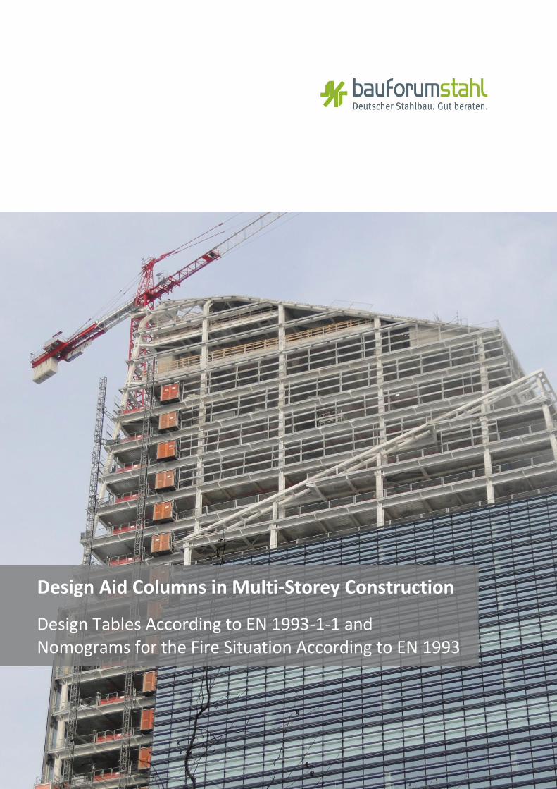
Design Aid Columns in Multi-Storey Construction
Design Tables According to EN 1993-1-1 and Nomograms for the Fire Situation According to EN 1993

2 Columns in Multi-Storey Construction
A |Design tables for flexural buckling Seite 4
A.1 |Introduction ..................................................................................................................................... Seite 4
A.1.1 |Flexural buckling resistances of HEA sections in steel grade S355 with γM1=1,1 ........................ Seite 5
A.1.2 |Flexural buckling resistances of HEA sections in steel grade S460M with γM1=1,1 ..................... Seite 6
A.1.3 |Flexural buckling resistances of HEB sections in steel grade S355 with γM1=1,1 ........................ Seite 7
A.1.4 |Flexural buckling resistances of HEB sections in steel grade S460M with γM1=1,1 ..................... Seite 8
A.1.5 |Flexural buckling resistances of HEM sections in steel grade S355 with γM1=1,1 ....................... Seite 9
A.1.6 |Flexural buckling resistances of HEM sections in steel grade S460M with γM1=1,1 .................... Seite 10
A.1.7 |Flexural buckling resistances of HD sections in steel grade S355 with γM1=1,1 .......................... Seite 11
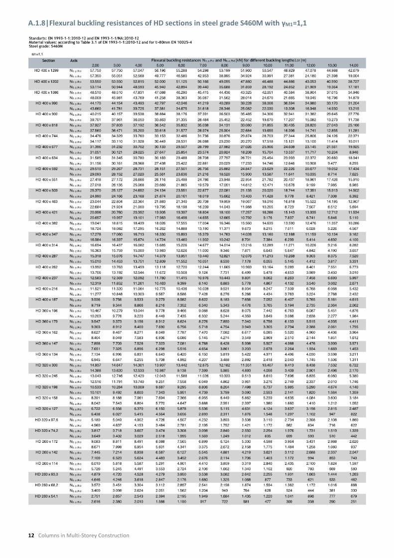
A.1.8 |Flexural buckling resistances of HD sections in steel grade S460M with γM1=1,1 ....................... Seite 12
……………………………………………………………………………………………………………………………………………………………………………
Columns in multi-storey construction ..................................................................................................... Seite 12
1 |Introduction and general preliminary remarks ........................................................................ Seite 13
1.1 |Choice of cross-section and steel grade .................................................................................. Seite 14
2 |Design approach for columns according to EN 1993-1-1:2010-12 ............................................. Seite 16
2.1 |Design criteria ....................................................................................................................... Seite 16
2.1.1 |Materials ............................................................................................................................... Seite 17
2.1.2 |Classification of cross-sections ............................................................................................... Seite 17
2.1.3 |Categorisation using the buckling curve .................................................................................. Seite 22
2.2 |Verification of uniform structural elements with designed axial compression
(flexural buckling) according to EN 1993-1-1, item 6.3.1 ........................................................... Seite 22
2.3 |Verification of uniform structural elements with bending about the main axis
(torsional-flexural buckling) according to EN 1993-1-1, item 6.3.2 ............................................ Seite 24
2.3.1 |General case for torsional-flexural buckling according to EN 1993-1-1, item 6.3.2.2 ................. Seite 24
2.3.2 |Special case for torsional-flexural buckling – rolled cross-sections or similar welded
cross-sections – according to EN 1993-1-1, item 6.3.2.3 ........................................................... Seite 24
2.4 |Interaction verifications for uniform structural elements subjected to bending and
compression according to EN 1993-1-1, item 6.3.3 ................................................................... Seite 26
2.5 |Sample calculation for a column with designed axial compression (flexural buckling)
according to EN 1993-1-1, cf. Table A.1.1 ................................................................................. Seite 26
……………………………………………………………………………………………………………………………………………………………………………
3 | Fire protection ...................................................................................................................... Seite 27
3.1 | Basis of calculation ............................................................................................................... Seite 28
3.1.1 | Load-carrying capacity in the fire situation ............................................................................ Seite 28
3.1.2 | Boundary conditions ............................................................................................................. Seite 29
3.1.3 | Fire protection materials ....................................................................................................... Seite 30
3.2 | Method of calculation ........................................................................................................... Seite 30
3.2.1 | Critical temperature .............................................................................................................. Seite 30
3.2.2 | Fire resistance rating ............................................................................................................. Seite 30
3.2.3 | Structural elements with Class 4 cross-sections ...................................................................... Seite 33
3.3 | Sample calculations .............................................................................................................. Seite 33
3.3.1 | Example 1 – protected storey-high column ............................................................................ Seite 33
3.3.2 | Example 2 – unprotected storey-high column ........................................................................ Seite 34
Nomogram B.1: Development of steel temperatures as a function of the fire duration ..................... Seite 35
Nomogram B.2: Critical temperature θa,cr for compression members in S355 steel grades ............... Seite 36
Nomogram B.3: Critical temperature θa,cr for compression members in S460M steel grades ............ Seite 37
……………………………………………………………………………………………………………………………………………………………………………
4 |Literature .............................................................................................................................. Seite 38

bauforumstahl 3
Imprint
Design Aid Columns in Multi-Storey Construction – Design Tables According to EN 1993-1-1 and Nomograms for the Fire Situation According to EN 1993-1-2 No. B 503 Publisher: bauforumstahl e.V. | Sohnstraße 65 | 40237 Düsseldorf Postfach 104842 | 40039 Düsseldorf T: +49 (0)211.6707.828 | F: +49 (0)211.6707.829 [email protected] | www.bauforumstahl.de www.facebook.com/bauforumstahl
© bauforumstahl e.V., Düsseldorf, August 2016
All rights are reserved.
Reproduction of this publication ─ also in part ─ is only permitted with the written permission of the publisher and with a clear reference to the source.
The greatest possible care was exercised when compiling all of the texts, formulae, figures, drawings and tables. Nevertheless, mistakes cannot be ruled out completely.
bauforumstahl cannot accept responsibility for faulty information and its consequences. No legal claims can there-fore be accepted for use of the data provided. We are always grateful for suggestions and proposals for improve-ment.
All Decimal and Thousands Separators are in German format.
Authors: Dr.-Ing. Julija Ruga, bauforumstahl e.V. Dipl.-Ing. Marc May, ArcelorMittal Europe Dipl.-Ing. Sivo Schilling, bauforumstahl e.V.
Cover photo: Torre Diamante in Milan, 2012, © bauforumstahl e.V.

4 Columns in Multi-Storey Construction
A|Design tables for flexural buckling
A.1|Introduction The aim of this publication is to make tables available which will enable the user to quickly read off the loadability of storey-high columns as a function of the storey height. In structural engineering the storey height is usually also the same as the relevant buckling length. Even when the buckling length does not correspond to the storey height, for example because of fixed supports at the end of the bars, the flexural buckling resistance for the actual buckling length can be taken from the tables.
The design tables are also generally valid for compression members, e.g. posts, struts and flanges of trusses with their relevant buckling lengths.
All tables in Section A are based on the design concept of EN 1993-1-1 [1].
The design tables are based on the flexural buckling resistances for the following variables:
Cross-sections of rolled sectioins HEA, HEB, HEM or HD
Steel grade: S355 or S460M
Buckling length: 2 m to 14 m
For the German version of the publication, the nominal values of the yield stress fy and the tensile strength fu for nominal thicknesses up to 80 mm were taken from Table 1 of EN 1993-1-1 [1] in accordance with EN 1993-1-1/NA [2]. For nominal thicknesses over 80 mm, Table 2 applies correspondingly in accordance with EN 10025-2 [9] and EN 10025-4 [11]. The flexural buckling resistances of the German version of the publication were calculated using the partial safety factor for the loadability at loss of stability γM1=1,1 according to EN 1993-1-1/NA [2].
This publication uses Table 2 for the mechanical properties according to EN 1993-1-1 and the partial safety factor γM1=1,0 recommended value according to EN 1993-1-1). For each European country, the material properties have to be taken into consideration according to Table 1 or Table 2 and the partial safety factors γM1, as regulated in the respective National Annexes to EN 1993-1-1.
Additional bending moments and, if applicable, the resultant interaction verifications were not considered.
The flexural buckling resistances given in the tables do not replace verification of the load-carrying ca-pacity and serviceability compliant with the stand-ards.

A.1.1|Flexural buckling resistances of HEA sections in steel grade S355 with γM1=1,1
bau
foru
mstah
l 5

A.1.2|Flexural buckling resistances of HEA sections in steel grade S460M with γM1=1,1
6 C
olu
mn
s in M
ulti-Sto
rey Co
nstru
ction

A.1.3|Flexural buckling resistances of HEB sections in steel grade S355 with γM1=1,1
bau
foru
mstah
l 7

A.1.4|Flexural buckling resistances of HEB sections in steel grade S460M with γM1=1,1
8 C
olu
mn
s in M
ulti-Sto
rey Co
nstru
ction

A.1.5|Flexural buckling resistances of HEM sections in steel grade S355 with γM1=1,1
bau
foru
mstah
l 9

A.1.6|Flexural buckling resistances of HEM sections in steel grade S460M with γM1=1,1
10
Co
lum
ns in
Mu
lti-Storey C
on
structio
n

bauforumstahl 11
A.1.7|Flexural buckling resistances of HD sections in steel grade S355 with γM1=1,1
12 Columns in Multi-Storey Construction
A.1.8|Flexural buckling resistances of HD sections in steel grade S460M with γM1=1,1

bauforumstahl 13
Columns in Multi-Storey Construction
1|Introduction and general preliminary remarks
Columns serve not only to transfer the load vertically but also represent an important design element of a building. In doing so the columns in the outside area, such as façade columns or free-standing foyer col-umns, are often of greater significance from a design point of view than the internal columns. The façade columns should create as filigree an effect and the largest transparency as possible and allow a high level of incident daylight into the building interior. However, even highly stressed interior columns can be executed with highly efficient and compact cross-sections thanks to the steel construction.
Columns are mainly subjected to compressive forces. If the load is applied axially, which is desirable, bend-ing moments do not occur and it is only necessary to provide verification of flexural buckling. As columns can buckle in both directions, the so-called ‘weak’ axis is decisive for the calculation when the buckling length is the same for both axes. It is therefore rec-ommended to use cross-sections that exhibit equally large flexural buckling resistance in both directions, such as the hot-rolled wide-flange beams of the HE and HD series. HEA sections are suitable for smaller loads, while HEB, HEM and HD sections are worth considering for larger loads. HD sections are particu-larly well suited for very large loads. All of these sections have a favourable material price per tonne. More important, though, is that structurally they allow simple, easily accessible and thus very eco-nomic connections to be made. In addition, it is pos-sible to install them vertically inside the columns without difficulty.
It is beneficial that the outside dimensions of the columns remain almost unchanged over the height of the building, for example in order to allow stand-ardised elements to be installed. The columns of a section series (HE or HD) with the same nominal height usually have the same internal dimensions. With the external dimensions, HEA sections are somewhat shorter than HEB sections, which in turn are somewhat shorter and thinner than HEM sec-tions. In between there may be smaller HD sections (Fig. 1). HE sections are limited to a section width of some 300 mm whereas large HD sections reach sec-tion widths of well over 400 mm.
In order to match the dimensions of the columns storey-wise to the loads and to thus use them opti-mally, it is recommended to graduate the column sections over the height of the building from HEA in the upper floors via HEB through to HD or HEM sec-tions. Besides the section cross-section, varying the steel grade can also lead to better utilisation of the columns (Fig. 2).
Bild 1: Comparison of internal and external dimensions of the HE and HD section series for a nominal height of 260 mm
Bild 2 : Various possibilities for optimising the column cross-section over the height of the building

14 Columns in Multi-Storey Construction
1.1|Choice of cross-section and steel grade
S235, which was once the most widely used steel grade, is increasingly proving to be less economical and thus less appropriate for multi-storey buildings especially for columns made from hot-rolled sec-tions. It is particularly economical to use the stand-ard grade S355 and often a further optimisation of the high-strength steel S460.
A high yield stress enables the cross-section to be reduced and consequently material to be saved. In addition to savings in material and material costs there are also savings in processing costs as a result of a reduced welding volume, smaller areas to be coated and often more favourable transport.
As an example, the increase in the flexural buckling resistance about the weak axis in both of the steel grades mentioned previously is shown in Diagram 1 for different buckling lengths and sections. At larger buckling lengths, the increase in the flexural buckling resistance due to the use of higher steel grades is less in percentage terms because the specific slenderness ratio is linearly dependent on the buckling length but only on the square root of the
yield stress and there are small differences between the relevant buckling curves for large specific slenderness ratios than for medium-sized ratios (see Section 2.2).
The dependence of the flexural buckling resistance for the HE and HD section series for the S355 and S460M steel grades and a buckling length of 4,0 m is shown in Diagram 2. For reasons of clarity, only sec-tions with a self-weight up to 400 kg/m are shown.
The ‘kinks’ in the curves result on the one hand from a change in the correlation with the buckling curves from EN 1993-1-1 (Table 7) at h/b > 1,2 and on the other to the reduction in the yield stress in accord-ance with Table 1.
It can be clearly seen that if the same steel grade is used, the HEA sections offer the most favourable options for implementation from a material con-sumption point of view up to 125 kg/m (HEA 400). From 134 kg/m (HD360x134), the HD sections are the most favourable.
Diagram 1: Flexural buckling resistances of the sections in Fig. 1 for S355 and S460M (intermediate values interpolated)

bauforumstahl 15
Diagram 2: V Flexural buckling resistances as a function of the section series and the steel grade (intermediate values interpolated)
Only HD400 sections are available for the load range from above approx. 10.000 kN (S355) or 14.000 kN (S460M) up to more than 50.000 kN (Tables A.1.7 and A.1.8). In addition, because the HD360 and HD400 section series always have the same inside dimensions they have the advantage that column joints can be carried out easily [22]
At a constant flexural buckling resistance and a con-stant buckling length of 4,0 m, the optimisation can be explained as follows:
For the section chosen as an example, HEM320 in S355 with mass G = 245 kg/m, the cross-sectional area A = 312 cm2 and the radius of gyration iz = √(Iz/A) = 7,95 cm, one can say: Nb,Rd = 7553 kN (Di-agram 2 and Table A.1.5).
Approximately the same flexural buckling resistance Nb,Rd = 7583 kN applies for the section HD360x162 in S460M with G = 162 kg/m, A = 206,3 cm2 and iz = √(Iz/A) = 9,49 cm (Diagram 2 and Table A.1.8).
Thus in this example there is a material saving of 34% as a result of optimising the cross-section and using high-strength steel S460M.
In Diagram 3, the flexural buckling resistances of sections from different section series with approxi-mately the same cross-sectional area of 200 cm² (HEA500, HEB400, HEM240 and HD360x162) are compared because both the cross-sectional area and the yield stress are included in the calculation of the specific slenderness ratio and thus in the reduction factor, as well as directly in the calculation of the flexural buckling resistance.
The following variables are important for determin-ing the specific slenderness and thus the flexural buckling resistance:
The buckling length Lcr.of the compression mem-ber.
The radii of gyration i about the respective cross-section axis (here shown about the design-relevant weak axis z): sections with larger radii of gyration (here iz) exhibit a significantly greater flexural buckling resistance for the same cross-sectional area. This is very clearly apparent with the HD sections, as indicated by the statically fa-vourable material distribution for loads about the weak axis.
The steel grade together with the corresponding nominal value of the yield stress fy and, depend-ing on this, its allocation to a buckling curve in Di-agram 5.

16 Columns in Multi-Storey Construction
The increase in the load-carrying capacity for a simi-lar cross-sectional area and a constant buckling length of 4,0 m can be explained as follows:
For the section chosen as an example, HEM240 in S355 with G = 157 kg/m, A = 199.6 cm2 and iz =
(Iz/A) = 6,39 cm one can say: Nb,Rd = 4188 kN (Dia-gram 2, Diagram 3 and Table A.1.5).
For a similar cross-sectional area and a similar weight, a flexural buckling resistance of Nb,Rd = 7583 kN (Diagram 2, Diagram 3 and Table A.1.8) applies for the HD360x162 section in S460M with G = 162 kg/m, A = 206,3 cm2 and iz = √ (Iz/A) = 9,49 cm.
Thus for this example an increase there is an in-crease in load-carrying capacity of 81% as a result of optimising the cross-section and using the high-strength steel S460M.
2|Design approach for columns in accordance with EN 1993-1-1:2010-12
The columns are investigated for flexural buckling or torsional-flexural buckling stability according to EN 1993-1-1, item 6.3.1 [1] under the influence of the sole action of an axial force. Under the influence of additional bending moments resulting from eccen-tric application of the load, the effects of bracing or wind loading, columns have to be verified using the interaction equations on the equivalent member according to [1], item 6.3.3.
2.1|Design criteria
Before the stability verification can be carried out, the steel grade and the cross-section must first be selected (Section 1.1).
Diagramm 3: Dependence of the flexural buckling resistance of the section and the steel grade for similar cross-sectional areas (intermedi-ate values interpolated)
HEA500 HEB400 HEM240 HD360x162

bauforumstahl 17
2.1.1|Materials
The choice of steel grade determines the mechanical properties of the basis material, i.e. the nominal values of the yield stress fy and the tensile strength fu. Table 1 presents a selection from Table 3.1 of EN 1993-1-1 [1] for the steels used in this publication.
Table 2 contains the nominal values of the yield stress fy of the steels being considered in accordance with the corresponding product standards that may be used alternatively according to [1] and [2].
It can be seen from Tables 1 and 2 that with increas-ing nominal thickness the nominal value of the yield stress fy decreases. This has to be taken into consid-eration accordingly in the design.
For sections with material thicknesses over 80 mm, the material properties according to the product standards EN 10025-2 for S355 and EN 10025-4 for S460M (Table 2 for t > 80 mm) were used to prepare the design tables.
All tables in Section A contain the reductions in the design yield stress in accordance with the standards [1] and [2].
Tabelle 1: Nominal values of the yield stress fy for hot-rolled structural steel in accordance with EN 1993-1-1, Table 3.1 [1]
* The steel grade corresponds to the steel type and product
thickness of the nominal thickness of the structural steel plate or here of the section flange
2.1.2|Classification of cross-sections
Once the cross-section has been defined, a cross-section classification is carried out in accordance with EN 1993-1-1, Section 5.5 [1]. The classification of the cross-sections covers limiting the loadability and the rotational capacity due to local buckling.
The suitability of a cross-section to elastic or plastic cross-sectional verification is expressed by its cross-section classification. EN 1993-1-1 [1] defines four cross-section classifications whose moment-rotation behaviour are shown in Diagram 4.
Diagram 4: Moment-rotation behaviour of the different cross-section classifications (Class 1-4)
Class 1 – Plastic hinges that can form and have adequate moment capacity and rotational capaci-ty according to the plastic analysis.
Class 2 – The plastic moment resistance is reached at limited rotational capacity.
Class 3 – The yield stress is reached in the ex-treme fibres, however as a result of localised buckling there is no usable plastic moment re-sistance.
Class 4 – Localised buckling occurs before the yield stress is reached. The determination of the effective values of the cross-section can be car-ried out according to EN 1993-1-5 [3].
Table 2: Nominal values of the yield stress fy for hot-rolled structural steel according to the product standards [9], [11]
The elements of the cross-section in compression are relevant for the classification of the cross-
sections in accordance with EN 1993-1-1 Table 5.2, whereby delimitation is by means of the maximum
Stahlgüte* Erzeugnisdicke t*
t ≤ 40 mm 40 mm < t ≤ 80 mm
fy in N/mm²
S355 355 335
S460M/ML 460 430
Werkstoffnorm Stahlgüte* Nenndicke t
t ≤ 16 mm 16 mm < t ≤ 40 mm
40 mm < t ≤ 63 mm
63 mm < t ≤ 80 mm
80 mm < t ≤ 100 mm
100 mm < t ≤ 150 mm
fy in N/mm²
EN 10025-2 [9] S355 355 345 335 325 315 295
EN 10025-4 [11] S460 M/ML 460 440 430 410 400 385

18 Columns in Multi-Storey Construction
slendernesses of the c/t ratios of the individual cross-section elements in compression. Here, c is the width or height and t is the material thickness of a cross-section element; ε is the specific yield stress, which depends on the steel grade (Table 4). There is a differentiation between pure compression, pure bending and combined compression and bending.
The classification is first carried out separately for the web and the flange. The total cross-section is defined by the highest and at the same time the most unfavourable class of it cross-section elements.
Table 3 summarises the classification criteria for the web as a cross-section element supported on both sides and for the flange as one supported on one side.
According to Para. 6.2.6 (6) of EN 1993-1-1, for column cross-sections with unstiffened web plate subjected to lateral forces and
verification of resistance to shear buckling according to EN 1993-1-5 is additionally required. To be on the safe side, it is recommended to use ɳ = 1,2 for steel grades up to S460, and ɳ = 1,0 for higher steel grades. In general, the shear buckling criterion is
only of significance for very tall supports with low web thicknesses, which are rarely used for compres-sively loaded columns verification of resistance to shear buckling according to EN 1993-1-5 is addition-ally required. To be on the safe side, it is recom-mended to use ɳ = 1,2 for steel grades up to S460, and ɳ = 1,0 for higher steel grades. In general, the shear buckling criterion is only of significance for very tall supports with low web thicknesses, which are rarely used for compressively loaded columns.
Columns in pure compression remain free from lat-eral forces, whereby the shear buckling criterion is not to be used for this case.
For information, Table 4 contains the evaluation of the criterion for shear buckling. Geometrically, the ratio hw/tw in Table 4 corresponds to the ratio c/t for the web in Table 3.
Another criterion that limits the slenderness of the web dc/tw is defined in EN 1993-1-8 [4]. For the structural element method, the slenderness of the web is limited to dc/tw ≤ 69 ε for the basic structural element 1 – column web under shear stress – so that a risk of buckling is excluded. As this criterion is much higher than the most unfavourable criterion for the classification of the web in compression, it is not relevant here.
Table 3: Maximum c/t ratios of the stressed cross-section elements
Table 4: Specific yield stress ɛ and criterion for shear buckling as a function of the steel grade
Class Cross-Section Elements Supported on Both Sides (Web)
Cross-Section Elements Supported on One Side (Flange)
Pure compression Pure bending Pure compression
1 c/t ≤ 33ɛ c/t ≤ 72ɛ c/t ≤ 9ɛ
2 c/t ≤ 38ɛ c/t ≤ 83ɛ c/t ≤ 10ɛ
3 c/t ≤ 42ɛ c/t ≤ 124ɛ c/t ≤ 14ɛ
4 c/t > 42ɛ c/t > 124ɛ c/t > 14ɛ
fy [N/mm²]
235 275 355 420 460
𝜺 = √𝟐𝟑𝟓/𝒇𝒚 1 0,92 0,81 0,75 0,71
72 / η = 60 60 55,2 48,6 45 42,5
72
w
w
t
h

bauforumstahl 19
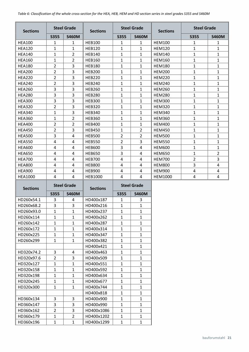
Classifications of the cross-section elements are given in Table 5 for the sections considered in this publication: HEA100 to HEA1000; HEB100 to HEB1000; HEM100 to HEM1000 and HD260x54,1 to HD400x1299. Only pure compression is considered for both the web and the flange because it is rele-
vant for the design tables. The resultant classifica-tion, which is relevant for the dimensioning of the whole cross-section, is shown in Table 6. The classifi-cations are given for the steel grades S355 and S460M.
Table 5: Classification of the cross-section elements for the HEA, HEB, HEM and HD section series in steel grade S355
Cross-Section Elements Supported on Both Sides (Web)
Cross-Section Elements Supported on One Side (Flange)
Steel Gra-de
Class Sections Sections
S355
( = 0,81)
1 c/t ≤ 33 ɛ = 26,73 HEA100 – HEA360
HEB100 – HEB450
HEM100 – HEM650
HD260x68,2 – HD260x299
HD320x97,6 – HD320x300
HD360x134 – HD360x196
HD400x187 – HD400x1299
c/t ≤ 9 ɛ = 7,29 HEA100 - HEA160
HEA340 – HEA1000
HEB100 – HEB1000
HEM100 – HEM1000
HD260x93 – HD260x299
HD320x127 – HD320x300
HD360x179 – HD360x196
HD400x187 – HD400x1299
2 c/t ≤ 38 ɛ = 30,78 HEA400 – HEA450
HEB500 – HEB550
HEM700
HD260x54,1
HD320x74,2
c/t ≤ 10 ɛ = 8,1 HEA180 – HEA240
HEA320
HD320x97,6
HD360x162
3 c/t ≤ 42 ɛ = 34,02 HEA500
HEB600 – HEB650
HEM800
c/t ≤ 14 ɛ = 11,34 HEA260 – HEA300
HD260x54,1 – HD260x68,2
HD320x74,2
HD360x134 – HD360x147
4 c/t > 42 ɛ = 34,02 HEA550 – HEA1000
HEB700 – HEB1000
HEM900 – HEM1000
c/t > 14 ɛ = 11,34

20 Columns in Multi-Storey Construction
Table 5 (continued): Classification of the cross-section elements for the HEA, HEB, HEM and HD section series in steel grade S460M
Cross-Section Elements Supported on Both Sides (Web)
Cross-Section Elements Supported on One Side (Flange)
Steel Gra-de
Class Sections Sections
S460M
( = 0,71)
1 c/t ≤ 33 = 23,43 HEA100 – HEA240
HEB100 – HEB400
HEM100 – HEM600
HD260x93 – HD260x299
HD320x127 – HD320x300
HD360x162 – HD360x196
HD400x187 – HD400x1299
c/t ≤ 9 = 6,39 HEA100 – HEA120
HEA400 – HEA1000
HEB100 – HEB1000
HEM100 – HEM1000
HD260x93 – HD260x299
HD320x127 – HD320x300
HD360x196
HD400x216 – HD400x1299
2 c/t ≤ 38 = 26,98 HEA260 – HEA400
HEB450 – HEB500
HEM650
HD260x68,2
HD320x97,6
HD360x134 – HD360x147
c/t ≤ 10 = 7,1 HEA140 – HEA160
HEA360
HD360x179
3 c/t ≤ 42 = 29,82 HEA450
HEB550
HEM700
HD260x54,1
HD320x74,2
c/t ≤ 14 = 9,94 HEA180 – HEA340
HD260x68,2
HD320x97,6
HD360x134 – HD360x162
HD400x187 4 c/t > 42 = 29,82 HEA500 – HEA1000
HEB600 – HEB1000
HEM800 – HEM1000
c/t >14 = 9,94 HD260x54,1
HD320x74,2
bauforumstahl 21
Table 6: Classification of the whole cross-section for the HEA, HEB, HEM and HD section series in steel grades S355 and S460M
Sections Steel Grade
Sections Steel Grade
Sections Steel Grade
S355 S460M S355 S460M S355 S460M
HEA100 1 1 HEB100 1 1 HEM100 1 1
HEA120 1 1 HEB120 1 1 HEM120 1 1
HEA140 1 2 HEB140 1 1 HEM140 1 1
HEA160 1 2 HEB160 1 1 HEM160 1 1
HEA180 2 3 HEB180 1 1 HEM180 1 1
HEA200 2 3 HEB200 1 1 HEM200 1 1
HEA220 2 3 HEB220 1 1 HEM220 1 1
HEA240 2 3 HEB240 1 1 HEM240 1 1
HEA260 3 3 HEB260 1 1 HEM260 1 1
HEA280 3 3 HEB280 1 1 HEM280 1 1
HEA300 3 3 HEB300 1 1 HEM300 1 1
HEA320 2 3 HEB320 1 1 HEM320 1 1
HEA340 1 3 HEB340 1 1 HEM340 1 1
HEA360 1 2 HEB360 1 1 HEM360 1 1
HEA400 2 2 HEB400 1 1 HEM400 1 1
HEA450 2 3 HEB450 1 2 HEM450 1 1
HEA500 3 4 HEB500 2 2 HEM500 1 1
HEA550 4 4 HEB550 2 3 HEM550 1 1
HEA600 4 4 HEB600 3 4 HEM600 1 1
HEA650 4 4 HEB650 3 4 HEM650 1 2
HEA700 4 4 HEB700 4 4 HEM700 2 3
HEA800 4 4 HEB800 4 4 HEM800 3 4
HEA900 4 4 HEB900 4 4 HEM900 4 4
HEA1000 4 4 HEB1000 4 4 HEM1000 4 4
Sections Steel Grade
Sections Steel Grade
S355 S460M S355 S460M
HD260x54.1 3 4 HD400x187 1 3
HD260x68.2 3 3 HD400x216 1 1
HD260x93.0 1 1 HD400x237 1 1
HD260x114 1 1 HD400x262 1 1
HD260x142 1 1 HD400x287 1 1
HD260x172 1 1 HD400x314 1 1
HD260x225 1 1 HD400x347 1 1
HD260x299 1 1 HD400x382 1 1
HD400x421 1 1
HD320x74.2 3 4 HD400x463 1 1
HD320x97.6 2 3 HD400x509 1 1
HD320x127 1 1 HD400x551 1 1
HD320x158 1 1 HD400x592 1 1
HD320x198 1 1 HD400x634 1 1
HD320x245 1 1 HD400x677 1 1
HD320x300 1 1 HD400x744 1 1
HD400x818 1 1
HD360x134 3 3 HD400x900 1 1
HD360x147 3 3 HD400x990 1 1
HD360x162 2 3 HD400x1086 1 1
HD360x179 1 2 HD400x1202 1 1
HD360x196 1 1 HD400x1299 1 1

22 Stützen im Geschossbau
2.1.3|Categorisation using the buckling curve
For verification of the resistance to flexural buckling, the selected cross-section is categorised using the buckling curves according to Table 6.2 of EN 1993-1-1; a selection of rolled, doubly symmetric cross-sections is given in Table 7.
The buckling curve to be used depends on the cross-section geometry and steel grade. This is because of the effect of imperfections that due to the use of the relevant buckling curve or the imperfection factor α are incorporated in the dimensioning. One differen-tiates between geometric and structural imperfec-tions. With respect to the yield stress, high-strength steels have lower residual stresses and thus smaller structural imperfections, and are thus categorised according to more favourable buckling curves.
For S355, sections with dimensional ratios h/b > 1,2 and plate thicknesses tf > 100 mm, such as HD400x900 to HD400x1299, are according to the buckling curve b for flexural buckling about the strong axis and to the buckling curve c for flexural buckling about the weak axis. For S460M, such sec-tions are according to the buckling curve a for flex-ural buckling about the strong axis and buckling curve b for flexural buckling about the weak axis. This categorisation is based on the results of a re-search project conducted at TU Eindhoven [23].
Table 7: Categorisation using the buckling curve
2.2|Verification of uniform structural elements
with designed axial compression (flexural
buckling) according to EN 1993-1-1, item
6.3.1
The verification is fulfilled if the design value of the action NEd does not exceed the design value of the flexural buckling resistance Nb,Rd.
𝑁𝐸𝑑
𝑁𝑏,𝑅𝑑≤ 1,0 mit
Nb,Rd is the design value of the resistance to flexural buckling. For Classes 1 to 3, this is calculated using the gross cross-sectional area A; for Class 4 the effective cross-sectional area Aeff determined in accordance with EN 1993-1-5 is used.
Here, fy is the yield stress and γM1 the partial safety factor. The recommended partial safety factor ac-cording to EN 1993-1-1 is γM1 = 1,0; by contrast, ac-cording to EN 1993-1-1/NA [2] γM1 = 1,1 applies to all stability cases in Germany.
The reduction factor χ for the relevant flexural buckling:
whereby:
Limits Displacement at right angles to axis
Buckling curve S 235
S 275
S 355
S 420
S 460
h / b > 1,2 tf ≤ 40 mm y-y
z-z
a
b
a0
a0
40 mm ≤ tf ≤ 100 mm
y-y
z-z
b
c
a
a h / b ≤ 1,2 tf ≤ 100 mm y-y
z-z
b
c
a
a tf > 100 mm y-y
z-z
d
d
c
c
1
,
M
yRdb
fAN
0,11
22
aber
22,015,0
bauforumstahl 23
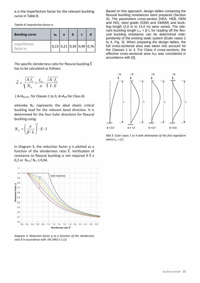
α is the imperfection factor for the relevant buckling curve in Table 8.
Tabelle 8: Imperfection factor α
The specific slenderness ratio for flexural buckling λ ̅has to be calculated as follows:
( A=Abrutto for Classes 1 to 3, A=Aeff for Class 4)
whereby Ncr represents the ideal elastic critical buckling load for the relevant bend direction. It is determined for the four Euler directions for flexural buckling using:
In Diagram 5, the reduction factor χ is plotted as a function of the slenderness ratio λ.̅ Verification of resistance to flexural buckling is not required if λ ̅ ≤ 0,2 or Ned / Ncr ≤ 0,04.
Diagram 5: Reduction factor χ as a function of the slenderness ratio λ̅ in accordance with EN 1993-1-1 [1]
Based on this approach, design tables containing the flexural buckling resistances were prepared (Section A). The parameters cross-section (HEA, HEB, HEM and HD), steel grade (S355 and S460M) and buck-ling length (2,0 m to 14,0 m) were varied. The rele-vant buckling length Lcr = β·L for reading off the flex-ural buckling resistance can be determined inde-pendently of the existing static system (Euler cases 1 to 4, Fig. 3). When preparing the design tables, the full cross-sectional area was taken into account for the Classes 1 to 3. For Class 4 cross-sections, the effective cross-sectional area Aeff was considered in accordance with [3].
Bild 3: Euler cases 1 to 4 with delineation of the first eigenform
where Lcr = L
Bending curve a0 a b c d
Imperfection factor α
0,13 0,21 0,34 0,49 0,76
EI
fAL
N
fA ycr
cr
y
IEL
Ncr
2

24 Columns in Multi-Storey Construction
2.3|Verification of uniform structural elements with bending about the main axis (torsional-flexural buckling) according to EN 1993-1-1, item 6.3.2
As columns are often subjected to a bending stress, even when it is small, the dimensioning principles for additional stability analyses will be given.
A verification for torsional-flexural buckling as a result of bending stress must be carried out if necessary, followed by an interaction verification for flexural buckling and torsional-flexural buckling.
The verification of resistance to torsional-flexural buckling is given if:
The design value of the flexural buckling resistance Mb,Rd is calculated as:
whereby: Wy = Wpl,y for Classes 1 and 2; Wy = Wel,y for lass 3, Wy = Weff,y for Class 4
EN 1993-1-1 [1] differentiates at this point between two cases: a ‘general case’ for all cross-sections and a ‘special case’ for doubly symmetric rolled and welded cross-sections of similar type.
2.3.1|General case for torsional-flexural buckling according to EN 1993-1-1, item 6.3.2.2
The reduction factor for torsional-flexural buckling ΧLT in the so-called general case is determined as:
with and
Here, Mcr is the ideal torsional-flexural buckling moment, which can be determined using solutions from the literature or with the help of dimensioning software.
In the so-called general case, the reduction factor χLT is determined using the imperfection factor αLT for torsional-flexural buckling. According to Table 8, the values of αLT and α for flexural buckling are quantitatively identical. Categorisation using the relevant buckling curve is carried out independently of the method of manufacture of the section (welded/rolled) and the geometric ratio of the height to the width (h/b). Table 9 contains the classification of the section according to these criteria.
Table 9: Recommended buckling curves for torsional-flexural buckling
Cross-section Limits Buckling curves
Rolled I-section h/b ≤ 2
h/b > 2
a
b
Welded I-section h/b ≤ 2
h/b > 2
c
d
Other cross-sections - d
2.3.2|Special case for torsional-flexural buck-
ling – rolled cross-sections or similar welded cross-sections – according to EN 1993-1-1, item 6.3.2.3
For the special case that there are rolled or welded sections of similar type, one may use more favourable torsional-flexural buckling curves for the calculation. To determine the reduction factor for torsional-flexural buckling χLT, a plateau value λL̅T,0 and a factor β are used for this special case.
where :
1
,
M
y
yLTRdb
fWM
0,1,
Rdb
Ed
M
M
cr
yy
LTM
fW
0,11
22
LT
LTLTLT
LT jedoch
LTLTLTLT
2)2,015,0
LTLTLT
LT 22
1
LTLTLTLTLT
2
0, )15,0

bauforumstahl 25
According to EN 1993-1-1 [1], λL̅T,0 = 0,4 (highest value) and β = 0,75 (lowest value) should be used. The categorisation of the sections to the ‘torsional-flexural buckling curves’ is summarised in Table 10.
Table 10: Recommended torsional-flexural buckling curves
Diagram 6: Flexural and torsional-flexural buckling curves
Buckling and torsional-flexural buckling curves are compared in Diagram 6. It is apparent that the plateau with χLT = 1 for the rolled or welded sections of similar type is extended from 0,2 to 0,4 and the corresponding torsional-flexural buckling curves for the special case are raised significantly compared with the buckling curves for the general case. For the special case, verification of the resistance to torsional-flexural buckling does not apply for slendernesses smaller than 0,4 and in the general case for slendernesses smaller than 0,2. This means a verification for resistance to torsional-flexural buckling for rolled or welded sections of similar type is not necessary if λ ̅LT ≤ 0,4 or converted Med / Mcr ≤ 0,16 applies.
To take the load-dependent moment distribution between the lateral supports into consideration, the reduction factor χLT may be modified as follows:
Cross-Section Limits Torsional-Flexural Buckling Curves
Rolled I-section h/b ≤ 2
h/b > 2
b
c
Welded I-section h/b ≤ 2
h/b > 2
c
d
1
1mod,mod,
2mod,
LT
LT
LT
jedochf
LTLT

26 Columns in Multi-Storey Construction
kc is a correction factor according to Table 11 or may be calculated as:
C1 corresponds exactly to the moment coefficient ζ for the fork bearing at the ends of the rods according to DIN 18800, Part 2, depending on the moment gradient.
Table 11: Recommended correction factors kc according to [1]
2.4| Interaction verifications for uniform structural elements subjected to bending and compression according to EN 1993-1-1, item 6.3.3
Structural elements loaded in compression and bending have to satisfy the requirements of the following interaction verifications:
With these verifications, consideration is given to the mutual interaction of the flexural buckling about both cross-section axes, the torsional-flexural buckling resulting from the bending moment My and the bending moment Mz. There are two methods available in [1] for determining the interaction factors kyy, kyz, kzy and kzz:
Alternative Method 1 according to Annex A
Alternative Method 2 according to Annex B
Practical application shows that Method 1 is better suited to computer-aided evaluation, whereas Method 2 is better for calculation by hand.
2.5|Sample calculation for a column with de-signed axial compression (flexural buck-ling) according to EN 1993-1-1, cf. Table A.1.1
Given situation: Column HEA320 in S355, both sides simply supported with a length of 5 m (β = 1,0).
Required: Flexural buckling resistance about the y and z axes
Step 1: Determine cross-section classification (Classes 1-4) HEA320 according to Table 6 Class 2 Step 2: Categorisation using the buckling curve h/b = 310/300 = 1,033 < 1,2 and tF = 15,5 mm < 100 mm for S355: displacement at right angles to the y-axis = buckling curve b, at right angles to the z-axis = buckling curve c Step 3: Imperfection factor α (cf. Table 8) α = 0,34 for the y-axis or
α = 0,49 for the z-axis
Moment Distribution kc
1
ψ = 1
1
1,33 − 0,33 ⋅ ψ
-1 ≤ ψ ≤ 1
0,940
0,897
0,910
0,860
0,763
0,816
0,1)8,00,21)1(5,01 2 LTckf
1
1
Ckc
1
1
,
,,
1
,
,,
1
M
Rkz
EdzEdz
yz
M
Rky
LT
EdyEdy
yy
M
Rky
Ed
M
MMk
M
MMk
N
N
1
1
,
,,
1
,
,,
1
M
Rkz
EdzEdz
zz
M
Rky
LT
EdyEdy
zy
M
Rkz
Ed
M
MMk
M
MMk
N
N

bauforumstahl 27
Step 4: Calculation of the flexural buckling resistance about the strong y-axis:
Step 5: Calculation of the flexural buckling resistance about the weak z-axis:
3|Fire protection
Fire protection is a further and important aspect for designing and dimensioning columns in multi-storey construction.
Steel is an inorganic construction material and with-out any verification is classified as being non-inflammable. However, the load-carrying capacity of unprotected steel structures decreases significantly on heating above about 500°C. Nevertheless, it is possible to achieve any required fire resistance rat-ing, defined by the so-called fire resistance class, by using appropriate fire protection measures. For this, a fire protection concept can be adapted to the use of the building.
Various fire protection measures are available to protect columns in the fire situation and thus achieve the required fire resistance rating:
Sprayed plaster coverings with a coarse sprayed surface, mainly used for less im-portant rooms with low aesthetic require-ments.
Coating - coatings that form an insulating layer where the steel construction remains visible and a protective foam forms in the fire situation
Encasement - covering the column cross-section with boards, blankets or shaped el-ements. The surfaces of the encasements are smooth and already prepared for the application of paint. The pre-fabricated boards can be bonded, clamped, bolted or nailed. The joints and seams are carried out in accordance with the manufacturer’s in-structions.
Hot design - dimensioning of the unprotect-ed steel column under the effect of temper-ature as a result of the fire
Composite cross-section with concrete - concrete-filled hollow composite columns, concrete-encased I-section columns, col-umns with concrete cores
Water cooling - filling with water, used mainly with hollow section columns, pre-vents excessive heating of the steel
An overview of the possible ways of providing fire protection for steel columns, their boundary condi-tions and execution is given in [20].
kN
IEL
N yycr
18990
22929210005001
14,322
,
482,018990
5,354,124
cr
y
N
fA
664,0
482,02,0482,034,015,0
2,015,0
2
2
892,0
482,0664,0664,0
11
2222
kNfA
NM
yyRdb 3581
1,1
5,354,124892,0
1
,,
kN
IEL
N zzcr
5785
6985210005001
14,322
,
874,05785
5,354,124
cr
y
N
fA
047,1
874,02,0874,049,015,0
2,015,0
2
2
616,0
874,0047,1047,1
11
2222
kNfA
NM
yzRdb 2473
1,1
5,354,124616,0
1
,,
28 Columns in Multi-Storey Construction
3.1|Basis of calculation
The necessary fire resistance of structural elements – expressed in terms of the classifications R30, R60, R90, etc. – is specified in state building codes or spe-cial building codes. The number of storeys, occupan-cy rate and use are usually considered in combina-tion with the existing fire loads. The measures for plant-related fire protection, such as fire-alarm sys-tems, fire-extinguishing systems (e.g. sprinklers) and/or smoke- or heat-extraction systems, have a beneficial effect on defining the fire resistance class.
The fire resistance classification of structural ele-ments is carried out using standardised fire tests or is based on a structural fire design. In this publica-tion, verification procedures based on calculation for internal, storey-high, hot-rolled, structural steel col-umns that are unprotected or protected by fire-protection materials are described on the basis of the simple method of calculation in accordance with EN 1993-1-2:2010-12, Section 4.2 [5], evaluated in nomograms [21] and documented with examples.
3.1.1|Load-carrying capacity in the fire situa-tion
The point in time at which the steel structural ele-ments can fail in the fire situation depends on
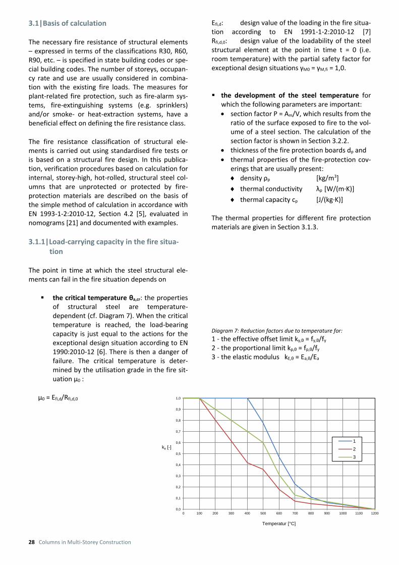
the critical temperature θa,cr: the properties of structural steel are temperature-dependent (cf. Diagram 7). When the critical temperature is reached, the load-bearing capacity is just equal to the actions for the exceptional design situation according to EN 1990:2010-12 [6]. There is then a danger of failure. The critical temperature is deter-mined by the utilisation grade in the fire sit-uation μ0 :
μ0 = Efi,d/Rfi,d,0
Efi,d: design value of the loading in the fire situa-tion according to EN 1991-1-2:2010-12 [7] Rfi,d,0: design value of the loadability of the steel structural element at the point in time t = 0 (i.e. room temperature) with the partial safety factor for exceptional design situations γM0 = γM,fi = 1,0.
the development of the steel temperature for
which the following parameters are important:
section factor P = Am/V, which results from the ratio of the surface exposed to fire to the vol-ume of a steel section. The calculation of the section factor is shown in Section 3.2.2.
thickness of the fire protection boards dp and
thermal properties of the fire-protection cov-erings that are usually present:
density ρp [kg/m3]
thermal conductivity λp [W/(m∙K)]
thermal capacity cp [J/(kg∙K)]
The thermal properties for different fire protection materials are given in Section 3.1.3.
Diagram 7: Reduction factors due to temperature for: 1 - the effective offset limit ky,θ = fy,θ/fy 2 - the proportional limit kp,θ = fp,θ/fy 3 - the elastic modulus kE,θ = Ea,θ/Ea
0,0
0,1
0,2
0,3
0,4
0,5
0,6
0,7
0,8
0,9
1,0
0 100 200 300 400 500 600 700 800 900 1000 1100 1200
kq [-]
Temperatur [°C]
1
2
3

bauforumstahl 29
3.1.2|Boundary conditions
Storey-high columns with designed axial compres-sion in the fire situation are calculated using the method of calculation in EN 1993-1-2:2010-12 [5]. Columns that are in danger of torsional-flexural buckling or designed to be subjected to compression and bending are excluded. The method of verifica-tion is applicable for the following boundary condi-tions:
structural steel grades according to EN 10025 (all parts)
sections of the cross-section classes 1, 2 and 3 (with Am/V > 10 m-1) according to [1]; for Class 4 cf. Section 3.2.3
a temperature rise in the fire area in accordance with the uniform temperature-time curve (UTTC) of ISO 834-1 [informative]
mechanical actions that are constant during the whole of the fire duration. The effects of thermal strains in the long axis of the structural element are ignored.
a uniform temperature distribution in the struc-tural element
a classification of the cross-sections as at normal temperatures, however with a reduced ɛ value
𝜀 = 0,85 ∙ √235/𝑓𝑦 and fy = yield stress at
20°C
Diagram 8: According to item 2.4.2(3) in [5]
a simplified determination of the loads in the
fire situation Efi,d according to [5], item 2.4.2(2) from the loads at room temperature Ed: Efi,d = ɳfi∙Ed with the reduction factor ɳfi according to Dia-gram 8 from item 2.4.2 (3) [5] or according to Ta-ble 12 from [21].
Table 12: Reduction factors ɳfi for vertical loads in the fire
situation as a function of the ratio Qk,1/Gk
Category
Qk Qk,i/Gk 0,5 1,0 2,0
kN/m2 2,i fi
A: Residential building 2,00 0,3 0,55 0,46 0,37
B: Office building 3,00 0,3 0,55 0,46 0,37
C: Assembly areas 5,00 0,6 0,62 0,56 0,51
D: Sales areas 5,00 0,6 0,62 0,56 0,51
E: Storage areas 7,50 0,8 0,67 0,63 0,60
F: Vehicles < 30 kN 2,50 0,6 0,62 0,56 0,51
G: Vehicles 30 – 160 kN 5,00 0,3 0,55 0,46 0,37
H: Roofs 0,75 0,0 0,48 0,35 0,23
For simplification fi = 0,7 can be assumed for actions of the category E and fi = 0,65 in all other cases .

30 Columns in Multi-Storey Construction
3.1.3|Fire protection materials
The properties of the fire protection materials (cf. Table 13) used in the method of calculation usually have to be determined in accordance with the re-spective test procedure of CEN/TS 13381-1, ENV 13381-2 and -4 [informative].
These standards include the requirement that fire protection material must remain intact during the decisive fire exposure and may not become de-tached from the structural element.
3.2|Method of calculation 3.2.1|Critical temperature
The critical temperature of hot-rolled structural steel θa,cr at time t as a function of the utilisation grade μ0
is determined using the function (4.22) in EN 1993-1-2, item 4.2.4 [5]. In the nomograms B.2 and B.3, this function is evaluated dependent on the slenderness ratio of the column for steel grades S355 and S460M.
Verification of compressively loaded columns in the fire situation is carried out with the help of nomo-grams using the following steps:
Steo 1:
Calculation of the utilisation grade μ0
𝜇0 = |𝑁𝑓𝑖,𝐸𝑑| (𝑓𝑦 ∙ 𝐴)⁄
Step 2:
Calculation of the specific slenderness ratio at the point in time t = 0:
�̅�𝜃,0 =𝛽𝑓𝑖
𝛽∙ �̅� = 𝛽𝑓𝑖 ∙
𝐿
𝑖𝑚𝑖𝑛 ∙ 𝜋∙ √
𝑓𝑦
𝐸𝑎
βfi Effective length factor according to [5] item 4.2.3.2 (4)
0,5 for columns in an internal storey 0,7 for columns in the uppermost storey β in all other cases, as for room temperature
Step 3:
Read off the critical temperature from the nomo-grams B.2 and B.3 as a function of the steel grade of the structural element.
3.2.2|Fire resistance rating In the fire situation, the temperature rise Δθa,t in a steel structural element during the time period Δt is calculated. The calculation is in accordance with EN 1993-1-2, item 4.2.5.1 [5] for unprotected, internal, steel structural elements and item 4.2.5.2 for pro-tected, internal, steel structural elements. A signifi-cant variable for the heating up is the section factor P, which is defined as the ratio of the fire-exposed surface area to the volume of the steel structural element. The larger this factor, the quicker the struc-tural element heats upch das Bauteil. The fire resistance rating of a structural element is read off from Nomogram B.1 based on further steps.
Table 13: Thermal properties of coverings
Material of the fire-protection cover-ing
p
[kg/m3]
p
W/(m∙K)]
cp
[J/(kg∙K)]
Machine-sprayed plaster
- Mineral fibres 300 0,12 1200 - Vermiculite or perlite 350 0,12 1200
Special plaster - Vermiculite/perlite + cement 550 0,12 1100 - Vermiculite/perlite + gypsum 650 0,12 1100
Boards - Vermiculite/perlite + cement 800 0,20 1200 - Fibre silicate or fibre calcium silicate 600 0,15 1200
- Fibre-cement 800 0,15 1200
- Plaster board 800 0,20 1700
Blankets - Mineral or rock
wool 150 0,20 1200
Dämmschichtbildner 0 ≤ 0,012 0

bauforumstahl 31
Step 4:
Calculation of the section factor P
P = Am/V
where Am is the circumference exposed to fire and V is the cross-sectional area. For unprotected and box-shaped covered H-sections, the contour of the rec-tangle circumscribing the cross-section can be taken to be Am (cf. Table 14). For profile protection of con-stant thickness, P should be calculated as the quo-tient of the cross-section circumference and the cross-sectional area.
Step 5:
Correction of the section factor P for unprotected structural elements
For unprotected structural elements with I or H cross-sections, the section factor given in Table 14 has to be multiplied by 0,9. Section factors that have already been determined for profile protected or box protected sections of the HEA, HEB, HEM and HD series exposed to fire on three or four sides are presented in Table 15.
Table 15: should not exceed h/4
HEA..
100 217 264 138 185
120 220 267 137 185
140 208 253 129 174
160 192 234 120 161
180 187 226 115 155
200 174 211 108 145
220 161 195 99 134
240 147 178 91 122
260 141 171 88 117
280 136 165 84 113
300 126 153 78 105
320 117 141 74 98
340 112 134 72 94
360 107 128 70 91
400 101 120 68 87
450 96 113 66 83
500 92 107 65 80
550 90 104 65 79
600 89 102 65 79
650 87 100 65 78
700 85 96 64 76
800 84 94 66 76
900 81 90 65 74
1000 81 89 66 74
Table 14 : Examples of the calculation of section factors
Unprotected I- and H-sections heated on four sides
I- and H-sections with box protection heated on four sides 1)
I- and H-sections with profile protection heated on four sides
b
h
b c
2
h
c1
b
h
P = 0,9∙(2b + 2h)/Aa P = (2b + 2h)/Aa P = U/Aa
Unprotected I- and H-sections heated on three sides
I- and H-sections with box protection heated on three sides 1)
I- and H-sections with profile protection heated on three sides
b
h
b c
2
h
c1
b
h
P = 0,9∙(b + 2h)/Aa P = (b + 2h)/Aa P = (U – b)/Aa
1) The air gaps c1 and c2 should not exceed h/4.

32 Columns in Multi-Storey Construction
Table 15 (continuation):Section factors for sections of the HEA, HEB, HEM and HD series
HEB..
100 180 218 115 154
120 167 202 106 141
140 155 187 98 130
160 140 169 88 118
180 131 159 83 110
200 122 147 77 102
220 115 140 72 97
240 108 131 68 91
260 105 127 66 88
280 102 123 64 85
300 96 116 60 80
320 91 110 58 77
340 88 106 57 75
360 86 102 56 73
400 82 97 56 71
450 79 93 55 69
500 76 89 54 67
550 76 88 55 67
600 75 86 56 67
650 74 85 56 66
700 72 82 55 65
800 72 81 57 66
900 70 78 57 65
1000 70 78 57 65
HEM..
100 96 116 65 85
120 92 111 61 80
140 88 106 58 76
160 83 100 54 71
180 80 96 52 68
200 76 92 49 65
220 73 88 47 62
240 61 73 39 52
260 59 72 39 51
280 59 71 38 50
300 50 60 33 43
320 50 60 33 43
340 50 60 34 43
360 51 61 34 44
400 52 62 36 45
450 53 62 38 47
500 55 63 39 48
550 56 64 41 50
600 57 65 42 51
650 58 66 44 52
700 59 67 45 53
800 60 68 48 55
900 70 78 57 65
1000 64 70 52 59
HD..
HD 260 x 54,1 176 214 108 146
HD 260 x 68,2 141 171 88 117
HD 260 x 93 105 127 66 88
HD 260 x 114 86 104 55 73
HD 260 x 142 71 86 46 60
HD 260 x 172 59 72 39 51
HD 320 x 74,2 152 184 95 127
HD 320 x 97,6 117 141 74 98
HD 320 x 127 91 110 58 77
HD 320 x 158 74 89 48 63
HD 320 x 198 60 72 39 51
HD 320 x 245 50 60 33 43
HD 320 x 300 42 50 28 36
HD 360 x 134 104 125 63 85
HD 360 x 147 95 114 58 78
HD 360 x 162 87 105 53 71
HD 360 x 179 79 95 49 65
HD 360 x 196 72 87 45 60
HD 400 x 187 78 94 47 64
HD 400 x 216 68 82 42 56
HD 400 x 237 63 76 38 52
HD 400 x 262 57 69 35 47
HD 400 x 287 52 63 32 43
HD 400 x 314 48 58 30 40
HD 400 x 347 44 53 28 37
HD 400 x 382 40 49 25 34
HD 400 x 421 37 45 23 31
HD 400 x 463 34 41 22 29
HD 400 x 509 31 38 20 27
HD 400 x 551 29 35 19 25
HD 400 x 592 28 33 18 23
HD 400 x 634 26 31 17 22
HD 400 x 677 25 30 16 21
HD 400 x 744 23 27 15 20
HD 400 x 818 21 25 14 18
HD 400 x 900 19 23 13 17
HD 400 x 990 18 22 12 16
HD 400 x 1086 17 20 11 15
HD 400 x 1202 15 18 11 14
HD 400 x 1299 15 17 10 13

bauforumstahl 33
For covered structural elements, heating up should be calculated using a thermal section factor TP:
𝑇𝑃 =𝐴𝑝
𝑉∙
𝜆𝑝
𝑑𝑝∙
1
1 + 𝜙 3⁄und 𝜙 =
𝜌𝑝 ∙ 𝑐𝑝
𝜌𝑎 ∙ 𝑐𝑎∙ 𝑑𝑝 ∙
𝐴𝑝
𝑉
where Ap is the internal execution of the fire protec-tion covering (cf. Table 14).
The parameter φ covers the inertia of the fire-protection system, ρa is the density and ca the ther-mal capacity of structural steel, which are taken to be constant as 7850 kg/m3 and 600 J/(kg∙K) respec-tively. For simplification, φ can also be ignored, i.e. taken to be 0. The time-temperature curves for cov-ered structural elements in Nomogram B.1 were determined without using the thermal inertia φ.
Step 6:
Read off the fire resistance rating (time) from the time-temperature Nomogram B.1, both for a pro-tected and an unprotected structural element.
3.2.3|Structural elements with cross-sections
of the Class 4
According to EN 1993-1-2, item 4.2.3.6 [5], the veri-fication for structural elements of Class 4 is deemed to have been provided as long as the steel tempera-ture θa does not exceed the critical temperature θcrit of 350°C. For the design operation using the nomo-grams it follows that the required thermal section factor can be read off from Nomogram B.1 for θcrit = 350°C and the necessary fire resistance rating in order to determine the thickness for suitable fire protection covering.
3.3|Sample calculations
3.3.1|Example 1 – protected storey-high
column
Given situation: Continuous HEB200 column in S355 in an office building. There are five storeys above the column and a 3 m-high internal column will be inves-tigated. The fire protection covering comprises box-shaped, 20 mm thick, sandwich type plaster boards.
Required: Fire resistance rating
Step 1: Utilisation grade
Assumption: The column supports 5∙2 = 10 girders with a total load in the fire situation of
𝑁𝑓𝑖,𝐸𝐷 = 500 𝑘𝑁
Classification of the cross-section in the fire situa-tion:
𝜀 = 0,85 ∙ √235/𝑓𝑦 = 069 → limit for Class 1
c/t ≤ 22,77
For HEB200: vorh. c/t = 14,9 ≤ 22,77 → cross-section is Class 1!
The utilisation grade is
𝜇0 =500
78,08∙35,5= 0,18
Step 2: Specific slenderness ratio for t = 0
The effective length factor for the fire situation is βfi = 0,5 (internal storey).
�̅�𝜃,0 = 𝛽𝑓𝑖 ∙𝐿
𝑖𝑚𝑖𝑛 ∙ 𝜋∙ √
𝑓𝑦
𝐸𝑎
= 0,5 ∙300
5,065 ∙ 3,14 √
355
210000
= 0,388
Step 3: From Nomogram B.2 it follows that approxi-mately θa,cr = 690°C
Step 4: Calculation of the section factor according to Table 14 or reading it off from Table 15
𝑃 =2𝑏 + 2ℎ
𝐴𝑎=
2 ∙ 20 + 2 ∙ 20
78,08= 1,024 𝑐𝑚−1
= 102 𝑚−1
Step 5: Correction of the section factor
𝜙 =𝜌𝑝 ∙ 𝑐𝑝
𝜌𝑎 ∙ 𝑐𝑎∙ 𝑑𝑝 ∙
𝐴𝑝
𝑉=
800 ∙ 1700
7850 ∙ 600∙ 0,02 ∙ 102
= 0,59
𝑇𝑃 =𝐴𝑝
𝑉∙
𝜆𝑝
𝑑𝑝∙
1
1 + 𝜙 3⁄=
102 ∙ 0,2
0,02 ∙ (1 +0,59
3 )
= 852 𝑊
𝑚3 ∙ 𝐾

34 Columns in Multi-Storey Construction
Step 6: Fire resistance rating
t > 120 minutes is read off from Nomogram B.1. The column fulfils the classification R 90!
3.3.2|Example 2 – Unprotected storey-high column
Given situation: HEA200 column in S355 for the top storey of the office building considered previously. The column does not have any fire protection cover-ing. For simplification, it will be assumed that the actions are the same as in Section 3.3.1 (conserva-tive).
Required: Check whether the column can be classi-fied as R 30
Step 1: Utilisation grade
Acting axial force ─ for simplification the deck is tak-en to be the deck of one storey.
𝑁𝑓𝑖,𝐸𝐷 = 500 5⁄ = 100 𝑘𝑁
The utilisation grade is
𝜇0 =100
53,83 ∙ 35,5= 0,052
Step 2: Specific slenderness ratio for t = 0
The effective length factor for the fire situation is βfi = 0,7.
�̅�𝜃,0 = 𝛽𝑓𝑖 ∙𝐿
𝑖𝑚𝑖𝑛 ∙ 𝜋∙ √
𝑓𝑦
𝐸𝑎= 0,7 ∙
300
4,98∙
1
93,9
= 0,449
Step 3: From Nomogram B.2 it follows that approxi-mately θa,cr > 900°C
Step 4: Calculation of the section factor (cf. Table 14)
𝑃 = 0,9 ∙2 ∙ 𝑏 + 2 ∙ ℎ
𝐴𝑎
= 0,9 ∙2 ∙ 20 + 2 ∙ 19
53,8= 131 𝑚−1
or using Table 15:
𝑃 = 0,9 ∙ 145 𝑚−1 = 131 𝑚−1
Step 5: not applicable
Step 6: Fire resistance rating
t > 46 minutes is read off from Nomogram B.1. The column fulfils the classification R 30!

Nomogram B.1: Dependence of the steel temperature on the fire duration (time) (from [21])
P = section factor for unprotected steel sections [m-1] TP = thermal section factor for covered steel sections [W/(m3∙K)]
0
100
200
300
400
500
600
700
800
900
0 10 20 30 40 50 60 70 80 90 100 110 120
Time [min]
Tem
pera
ture
[°C
]
200 100 60 40 30 25 20 15
2000
1500
1200 1000
800
10
700
600
500
400
350
300
250
200
150
100
P
T
Pbau
foru
mstah
l 35

Nomogram B.2: Critical temperature θa,cr for compression members in steel grade S355 (from [21])
Critical temperature Utilisation factor
Λ = �̅�𝜃,0 = specific slenderness ratio in the fire situation
100
200
300
400
500
600
700
800
900
0,0 0,1 0,2 0,3 0,4 0,5 0,6 0,7
Critical te
mpera
ture
qa
,cr
Utilisation factor m0
L 0,00
L 0,25
L 0,50
L 0,75
L 1,00
L 1,25
L 1,50
L 1,75
L 2,00
36
Stützen
im G
escho
ssbau

Nomogram B.3: Critical temperature θa,cr for compression members in steel grades S460M (from [21])
Λ = �̅�𝜃,0 = specific slenderness ratio in the fire situation
100
200
300
400
500
600
700
800
900
0,0 0,1 0,2 0,3 0,4 0,5 0,6 0,7
Critical tem
pera
ture
qa
,cr
Utilisation factor m0
L 0,00
L 0,25
L 0,50
L 0,75
L 1,00
L 1,25
L 1,50
L 1,75
L 2,00
bau
foru
mstah
l 37
38 Stützen im Geschossbau
4|Literature
[1] EN 1993-1-1:2010-12 – Eurocode 3: Design of steel structures - Part 1-1: General rules and rules for build-
ings [2] EN 1993-1-1/NA: 2010-12 – National Annex - Eurocode 3: Design of steel structures - Part 1-1: General
rules and rules for buildings [3] EN 1993-1-5:2010-12 – Eurocode 3: Design of steel structures - Part 1-5: Plated structural elements [4] EN 1993-1-8:2010-12– Eurocode 3: Design of steel structures - Part 1-8: Design of joints [5] EN 1993-1-2:2010-12 - Eurocode 3: Design of steel structures - Part 1-2: General rules - Structural fire
design
[6] EN 1990:2010-12 - Eurocode: Basis of structural design [7] EN 1991-1-2:2010-12 - Eurocode 1: Actions on structures - Part 1-2: General actions - Actions on struc-
tures exposed to fire [8] EN 10025 -1:2004 - Hot rolled products of structural steels - Part 1: General technical delivery conditions [9] EN 10025-2:2004 - Hot rolled products of structural steels - Part 2: Technical delivery conditions for non-
alloy structural steels [10] EN 10025-3:2004 - Hot rolled products of structural steels - Part 3: Technical delivery conditions for nor-
malized/normalized rolled weldable fine grain structural steels [11] EN 10025-4:2004 - Hot rolled products of structural steels - Part 4: Technical delivery conditions for ther-
momechanical rolled weldable fine grain structural steels [12] Kindmann, R., Krahwinkel, M: Stahl- und Verbundkonstruktionen, B.G. Teubner Stuttgart Leipzig, 1999 [13] Kindmann, R., Ludwig, C.: Zur Tragfähigkeit von Stabquerschnitten nach EN 1993-1-1, Teil 1, Stahlbau 81
(2012), Heft 4, Seiten 257-264 und Teil 2, Stahlbau 81 (2012), Heft 5, Seiten 353-357 [14] Kindmann, R., Kraus, M., Niebuhr, H.-J.: Stahlbau Kompakt, Bemessungshilfen, Profiltabellen, Verlag
Stahleisen GmbH, Düsseldorf, 2. Auflage 2008 [15] Kuhlmann, U., Froschmeier, B., Euler, M.: Allgemeine Bemessungsregeln, Bemessungsregeln für den
Hochbau – Erläuterungen zur Struktur und Anwendung von EN 1993-1-1, Stahlbau 79 (2010), Heft 11, Sei-ten 779-792
[16] Stroetmann, R., Lindner, J.: Knicknachweise nach EN 1993-1-1, Stahlbau 79 (2010), Heft 11, Seiten 793-808
[17] Stahlbau Kalender 2011, Eurocode 3 – Grundnorm Verbindungen, 13 Jahrgang [18] Hart, F., Henn, W., Sonntag, H.: Stahlbauatlas Geschossbauten, zweite Auflage, 1982 [19] bauforumstahl e.V., Schilling, S: Beispiele zur Bemessung von Stahltragwerken nach EN 1993 Eurocode 3,
2011 [20] Dokumentation 662, Brandschutz von Stahlbauteilen, Sonderdruck aus dem Brandschutzatlas, Herausge-
ber BAUEN MIT STAHL e.V., 2007 [21] Schilling, S.: Feuerwiderstand von Bauteilen aus Stahl, Nomogramme für die Berechnung des Feuerwider-
standes von Stahlbauteilen gemäß EN 1993-1-2:2005, http://www.bauforumstahl.de/upload/documents/brandschutz/nomogramme_en.pdf
[22] Hauke, B., Manganelli, E., Piccolin, G., May, M.: Torre Diamante – Ein flexibler Büroturm im Herzen Mai-lands, Sonderdruck aus VDI-Jahresausgabe 2012/2013, Seiten 32-39
[23] http://www.sciencedirect.com/science/article/pii/S0143974X13001752 Informative: ISO 834-1:1999-09, Fire-resistance tests - Elements of building construction - Part 1: General requirements CEN/TS 13381-1, Test methods for determining the contribution to the fire resistance of structural members - Part 1: Horizontal protective membranes ENV 13381-2:2002, Test methods for determining the contribution to the fire resistance of structural members - Part 2: Vertical protective membranes ENV 13381-4:2002, Test methods for determining the contribution to the fire resistance of structural members - Part 4: Applied passive protection to steel members


Mitglieder bauforumstahl . . . . . . . . . . . . . . . . . . . . . . . . . . . . . . . . . . . . . . . . . . . . . . . . . . . . . . . . . . . . . . . . . . . . . . . . . . . . . . . . . . . . . . . . . . . . . . . . . . . . . . . . . . . . . . . .
Interessengemeinschaft Stahlhandel im bauforumstahl (IGS) . . . . . . . . . . . . . . . . . . . . . . . . . . . . . . . . . . . . . . . . . . . . . . . . . . . . . . . . . . . . . . . . . . . .
Verbände . . . . . . . . . . . . . . . . . . . . . . . . . . . . . . . . . . . . . . . . . . . . . . . . . . . . . . . . . . . . . . . . . . . . . . . . . . . . . . . . . . . . . . . . . . . . . . . . . . . . . . . . . . . . . . . . . . . . . . . . . . . . . . . . . . . . . . .
Sohnstraße 65 | 40237 Düsseldorf
Postfach 10 48 42 | 40039 Düsseldorf
T: +49 (0)211.6707.828 | F: +49 (0)211.6707.829
[email protected] | www.bauforumstahl.de
Ken
nu
ng
Dru
ckn
um
me
r: B
50
3