Embed Size (px)
Citation preview
DEPARTMENT OF TRANSPORTATION 1401 EAST BROAD STREET
RICHMOND, VIRGINIA 23219-2000 Gregory A. Whirley Commissioner
January 13, 2014
Order No.: F24 Route: 60 Project: (NFO)0060-063-587, N501 FHWA: STP-PM04(400) District: Richmond County: New Kent Bids: January 22, 2014
To Holders of Bid Proposals:
Please make the following changes in your copy of the bid proposal for the captioned project:
BID PROPOSAL Substitute Cover as Description has been revised.
Delete Form C21B
Delete Form C21C
Substitute Form C-7 as Description has been revised.
Substitute Bid Item Sheets as they have been revised.
Substitute Table of Contents for Provisions as Special Provision Copied Note Section 512 Maintenance of Traffic (Stand-Alone) Paving Projects; Special Provision S509B01 - Patching Hydraulic Cement Concrete Pavement; and Special Provision S512N00 - Police Assistance for Paving Operations have been deleted and Special Provision Copied Note (c108lg0) Sec. 108.06(b) Liquidated Damages; Special Provision Copied Note Cancelled Activity Notification; Special Provision Copied Note Virginia Test Method, VTM-102; Special Provision SS24701 - Supp. Sec. 247-Reflective Sheeting; Special Provision SS21402-Supp. Sec. 214-Hydraulic Cement; Special Provision SS21501-Supp. Sec. 215-Hydraulic Cement Concrete Admixtures; Special Provision SS21706-Supp. Sec. 217-Hydraulic Cement Concrete; Special Provision Section 108.02-Limitation of Operations; and Special Provision Section 704-Pavement Markings & Markers have been added.
Substitute page 2 as Special Provision Copied Note Section 512 Maintenance of Traffic (Stand-Alone) Paving Projects has been deleted.

January 13, 2014 Order No.: F24
Substitute pages 82 through 89 as Special Provision S509B01 - Patching Hydraulic Cement Concrete Pavement has been deleted.
Substitute page 90 as Special Provision S512N00 - Police Assistance for Paving Operations has been deleted.
Substitute pages 120 through 129 as the No Plan Assembly has been revised.
Add pages 130 through 160 as Special Provision Copied Note (c108lg0) Sec. 108.06(b) Liquidated Damages; Special Provision Copied Note Cancelled Activity Notification; Special Provision Copied Note Virginia Test Method, VTM-102; Special Provision SS24701 - Supp. Sec. 247-Reflective Sheeting; Special Provision SS21402-Supp. Sec. 214-Hydraulic Cement; Special Provision SS21501-Supp. Sec. 215-Hydraulic Cement Concrete Admixtures; Special Provision SS21706-Supp. Sec. 217-Hydraulic Cement Concrete; Special Provision Section 108.02-Limitation of Operations; and Special Provision Section 704-Pavement Markings & Markers have been added. Don E. Silies State Contract Officer Assistant Division Administrator, Construction Division
JDRN Enclosures

ORDER NO.: F24 CONTRACT ID. NO.: C000104495N01
Form C-6a Rev. 3-22-05
CNSP (F) 1-9-06
COMMONWEALTH OF VIRGINIA DEPARTMENT OF TRANSPORTATION
BID PROPOSAL AND CONTRACT ROUTE NUMBER: 60 FHWA NUMBER: STP-PM04(400) PROJECT NUMBER: (NFO)0060-063-587, N501 COUNTY: NEW KENT DISTRICT: RICHMOND
DESCRIPTION: CONCRETE REPAIR FROM: 0.2 MI E HENRICO CL TO: JAMES CITY CL DATE BID SUBMITTED: 10:00 AM WEDNESDAY JANUARY 22, 2014

ORDER NO.: F24 CONTRACT ID. NO.: C000104495N01
Form C-48 Rev. 2-23-11
COMMONWEALTH OF VIRGINIA DEPARTMENT OF TRANSPORTATION
SUBCONTRACTOR/SUPPLIER SOLICITATION AND UTILIZATION FORM (ALL BIDDERS)
PROJECT NO.: (NFO)0060-063-587, N501 CONTRACT ID. NO.: C000104495N01 FHWA NO: STP-PM04(400) DATE SUBMITTED____________________ All bidders, including DBEs bidding as Prime Contractors, shall complete and submit the following information as requested in this form within ten (10) business days after the opening of bids. The bidder certifies this form accurately represents its solicitation and utilization or non-utilization, as indicated, of the firms listed below for performance of work on this contract. The bidder also certifies he/she has had direct contact with the named firms regarding participation on this project. BIDDER_________________________________SIGNATURE________________________________ TITLE_____________________________________________________________________________
SUBCONTRACTOR/SUPPLIER SOLICITATION AND UTILIZATION (ALL) VENDOR NUMBER
NAME OF SUBCONTRACTOR/SUPPLIER
TELEPHONE NUMBER
DBE OR NON-DBE
UTILIZED (Y/N)
NOTE: ATTACH ADDITIONAL PAGES, IF NECESSARY.
BIDDER MUST SIGN EACH ADDITIONAL SHEET TO CERTIFY ITS CONTENT AND COMPLETION OF FORM.

ORDER NO.: F24 CONTRACT ID. NO.: C000104495N01
FORM C-21B Rev 12-21-05 CONTRACT ID : C000104495N01 PAGE: 1 ORDER NO : F24 DATE: 11/18/13 BID ITEMS ELIGIBLE FOR FUEL ADJUSTMENT Instructions: This form shall be completed in accordance with the Special Provision for Optional Adjustment for Fuel. If you choose to have Fuel Adjustment applied to any of the items listed below, write the word "Yes" in the "OPTION" column beside the item. The form must be signed, dated, and submitted to the Contract Engineer within the timeframe required in the Special Provision. _________________________________________________________________________ | ITEM NUMBER | ITEM DESCRIPTION | FUEL | OPTION | | | | FACTOR | | | | | gal/unit | | |_______________|________________________________|_____________|_________| | 15290 |PATCHING CEM. CONC. | 2 | | | |PAVE. TY. CRCP-A | | | | | | | | |_______________|________________________________|_____________|_________| | | | | | |_______________|________________________________|_____________|_________| | | | | | |_______________|________________________________|_____________|_________| | | | | | |_______________|________________________________|_____________|_________| | | | | | |_______________|________________________________|_____________|_________| | | | | | |_______________|________________________________|_____________|_________| | | | | | |_______________|________________________________|_____________|_________| | | | | | |_______________|________________________________|_____________|_________| | | | | | |_______________|________________________________|_____________|_________| | | | | | |_______________|________________________________|_____________|_________| | | | | | |_______________|________________________________|_____________|_________| | | | | | |_______________|________________________________|_____________|_________| | | | | | |_______________|________________________________|_____________|_________| | | | | | |_______________|________________________________|_____________|_________| DATE:__________ SIGNATURE:___________________________________ ___________________________________ (Firm or Corporation) ___________________________________ (Vendor No.)

ORDER NO.: F24 CONTRACT ID. NO.: C000104495N01
FORM C-21C Rev 12-21-08 CONTRACT ID : C000104495N01 PAGE: 1 ORDER NO : F24 DATE: 11/18/13 BID ITEMS ELIGIBLE FOR STEEL PRICE ADJUSTMENT Instructions: This form shall be completed in accordance with the Special Provision. If you choose to have Steel Price Adjustment applied to any of the items listed below, write the word "Yes" in the "OPTION" column beside the item. The form must be signed, dated, and submitted to the Contract Engineer within the timeframe required in the Special Provision. ______________________________________________________________ | ITEM NUMBER | ITEM DESCRIPTION | OPTION | |_______________|________________________________|_____________| | 15290 |PATCHING CEM. CONC. | | | |PAVE. TY. CRCP-A | | | | | | |_______________|________________________________|_____________| | | | | |_______________|________________________________|_____________| | | | | |_______________|________________________________|_____________| | | | | |_______________|________________________________|_____________| | | | | |_______________|________________________________|_____________| | | | | |_______________|________________________________|_____________| | | | | |_______________|________________________________|_____________| | | | | |_______________|________________________________|_____________| | | | | |_______________|________________________________|_____________| | | | | |_______________|________________________________|_____________| | | | | |_______________|________________________________|_____________| | | | | |_______________|________________________________|_____________| | | | | |_______________|________________________________|_____________| | | | | |_______________|________________________________|_____________| | | | | |_______________|________________________________|_____________| DATE:__________ SIGNATURE:___________________________________ ___________________________________ (Firm or Corporation) ___________________________________ (Vendor No.)

ORDER NO.: F24 CONTRACT ID. NO.: C000104495N01
Form C-7DD Rev. 1-19-12
SHEET 1 of 2
TERMS OF THE PROPOSAL\CONTRACT COMMONWEALTH OF VIRGINIA
DEPARTMENT OF TRANSPORTATION SUBMITTED: 10:00 AM WEDNESDAY JANUARY 22, 2014
PROJECT NUMBER: (NFO)0060-063-587, N501 ROUTE NUMBER: 60 FHWA NUMBER: STP-PM04(400) DESCRIPTION: CONCRETE REPAIR FROM: 0.2 MI E HENRICO CL TO: JAMES CITY CL DISTRICT: RICHMOND COUNTY: NEW KENT I/we declare that no other person, firm or corporation is interested in this proposal; that I/we have carefully examined the plans, job specifications, current Road and Bridge specifications, and all other documents pertaining thereto and thoroughly understand the contents thereof; that I/we meet the prequalification requirements for bidding on this proposal; that I/we understand that the plans and current Road and Bridge specifications, are a part of this proposal; that all of the quantities shown herewith are a part of this proposal; that all the quantities shown herewith are approximate only; that I/we have examined the location of the proposed work and source of supply of materials; and that I/we agree to bind myself/ourselves upon award by the Commonwealth under this proposal to a contract with necessary surety bond to start work according to project specifications, and to complete all work in accordance with the plans, job specifications and current Road and Bridge Specifications within the time limit set forth in the contract.
COMPLETION DATE: 155 DAYS AND NO LATER THAN NOVEMBER 21, 2014 Contractor Selected Start Date ____________ + = _________________________ Month\Day\Year Consecutive Calendar days Selected Fixed Completion Date BID TOTAL $ Attached is a bond conforming to the requirements of the current Road and Bridge Specifications, it being understood that such bond is to be forfeited as liquidated damages if, upon acceptance of the terms of this proposal, I/we fail to execute the contract and furnish bond as provided in the current Road and Bridge Specifications.
(Names of Individual(S),Firm(S) Or Corporation)
Street Address City State Zip Code Vendor#/Fin#
Print Name Signature Title
In consideration of the commitments made as shown herein, the Commonwealth of Virginia by The Commonwealth Transportation Commissioner agrees to pay for all items of work performed and materials furnished at the unit price(s) and under the conditions set forth in this proposal, in witnessed by the affixing of the name below. Contract Execution Date By CHIEF ENGINEER
VIRGINIA DEPARTMENT OF TRANSPORTATION

ORDER NO.: F24 CONTRACT ID. NO.: C000104495N01
E22-PSPPROP VIRGINIA DEPARTMENT OF TRANSPORTATION PAGE: 2 CONTRACT ID : C000104495N01 STATE PROJ NUM: (NFO)0060-063-587, N501 FEDERAL PROJ NUM:STP-PM04(400) ORDER NO. F24 DATE 01/10/14 SCHEDULE OF ITEMS REVISED CONTRACTOR :____________________________________________________________________ ------------------------------------------------------------------------------------ | LINE| ITEM | ITEM | APP QTY. | UNIT PRICE | BID AMOUNT |------------| DESCRIPTION |-------------|--------------|-------------- |SPEC NUMBER | | UNITS | DOLLARS|CTS | DOLLARS|CTS ------------------------------------------------------------------------------------ | COMMON ITEMS ------------------------------------------------------------------------------------ |0010 | 10375|HYDRAULIC CEMENT | 9600.00| | |------------|PATCH CONC PVMT TYPE I |-------------| | |ATTD |I | SY | | | | ------------------------------------------------------------------------------------ | TOTAL ITEMS IN SECTION 0001 ALL PROJECT ITEMS | | | ------------------------------------------------------------------------------------ | TOTAL BID | | | ------------------------------------------------------------------------------------ | | | | | | |------------| |-------------| | | | | | | | | ------------------------------------------------------------------------------------ | | | | | | |------------| |-------------| | | | | | | | | ------------------------------------------------------------------------------------ | | | | | | |------------| |-------------| | | | | | | | | ------------------------------------------------------------------------------------ | | | | | | |------------| |-------------| | | | | | | | | ------------------------------------------------------------------------------------ | | | | | | |------------| |-------------| | | | | | | | | ------------------------------------------------------------------------------------ | | | | | | |------------| |-------------| | | | | | | | | ------------------------------------------------------------------------------------ | | | | | | |------------| |-------------| | | | | | | | | ------------------------------------------------------------------------------------ | | | | | | |------------| |-------------| | | | | | | | | ------------------------------------------------------------------------------------
ORDER NO.: F24 CONTRACT ID. NO.: C000104495N01
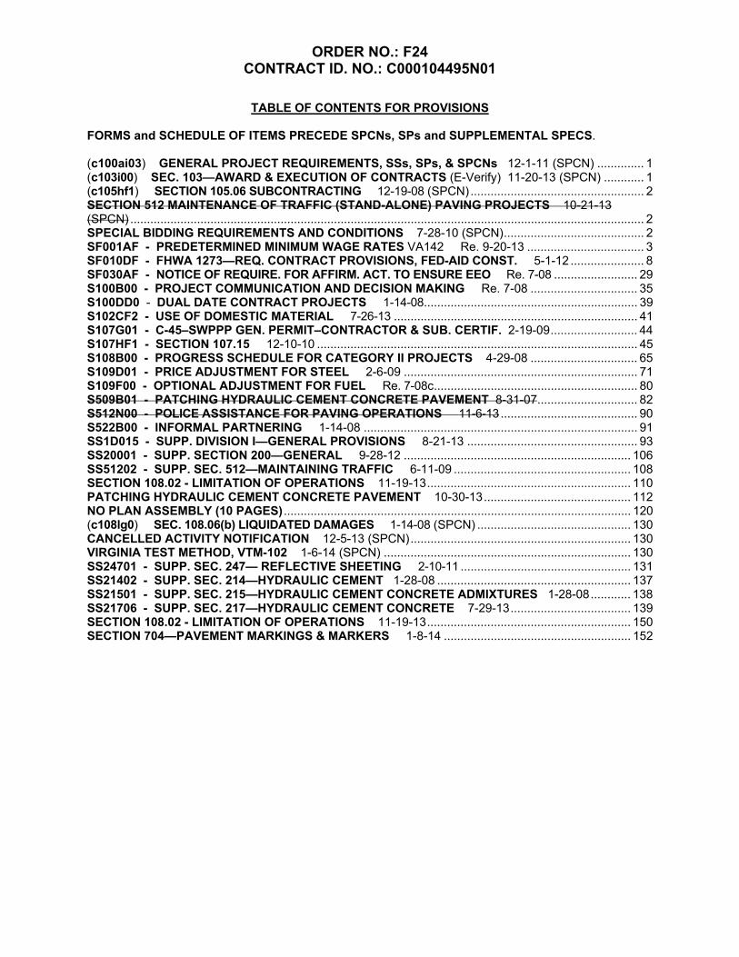
TABLE OF CONTENTS FOR PROVISIONS
FORMS and SCHEDULE OF ITEMS PRECEDE SPCNs, SPs and SUPPLEMENTAL SPECS. (c100ai03) GENERAL PROJECT REQUIREMENTS, SSs, SPs, & SPCNs 12-1-11 (SPCN) .............. 1 (c103i00) SEC. 103—AWARD & EXECUTION OF CONTRACTS (E-Verify) 11-20-13 (SPCN) ............ 1 (c105hf1) SECTION 105.06 SUBCONTRACTING 12-19-08 (SPCN) .................................................... 2 SECTION 512 MAINTENANCE OF TRAFFIC (STAND-ALONE) PAVING PROJECTS 10-21-13 (SPCN) .......................................................................................................................................................... 2 SPECIAL BIDDING REQUIREMENTS AND CONDITIONS 7-28-10 (SPCN) .......................................... 2 SF001AF - PREDETERMINED MINIMUM WAGE RATES VA142 Re. 9-20-13 ................................... 3 SF010DF - FHWA 1273—REQ. CONTRACT PROVISIONS, FED-AID CONST. 5-1-12 ...................... 8 SF030AF - NOTICE OF REQUIRE. FOR AFFIRM. ACT. TO ENSURE EEO Re. 7-08 ......................... 29 S100B00 - PROJECT COMMUNICATION AND DECISION MAKING Re. 7-08 ................................ 35 S100DD0 - DUAL DATE CONTRACT PROJECTS 1-14-08................................................................ 39 S102CF2 - USE OF DOMESTIC MATERIAL 7-26-13 ......................................................................... 41 S107G01 - C-45–SWPPP GEN. PERMIT–CONTRACTOR & SUB. CERTIF. 2-19-09 .......................... 44 S107HF1 - SECTION 107.15 12-10-10 ................................................................................................ 45 S108B00 - PROGRESS SCHEDULE FOR CATEGORY II PROJECTS 4-29-08 ................................ 65 S109D01 - PRICE ADJUSTMENT FOR STEEL 2-6-09 ...................................................................... 71 S109F00 - OPTIONAL ADJUSTMENT FOR FUEL Re. 7-08c ............................................................. 80 S509B01 - PATCHING HYDRAULIC CEMENT CONCRETE PAVEMENT 8-31-07 .............................. 82 S512N00 - POLICE ASSISTANCE FOR PAVING OPERATIONS 11-6-13 ......................................... 90 S522B00 - INFORMAL PARTNERING 1-14-08 .................................................................................. 91 SS1D015 - SUPP. DIVISION I—GENERAL PROVISIONS 8-21-13 ................................................... 93 SS20001 - SUPP. SECTION 200—GENERAL 9-28-12 .................................................................... 106 SS51202 - SUPP. SEC. 512—MAINTAINING TRAFFIC 6-11-09 ..................................................... 108 SECTION 108.02 - LIMITATION OF OPERATIONS 11-19-13 ............................................................. 110 PATCHING HYDRAULIC CEMENT CONCRETE PAVEMENT 10-30-13 ............................................ 112 NO PLAN ASSEMBLY (10 PAGES) ........................................................................................................ 120 (c108lg0) SEC. 108.06(b) LIQUIDATED DAMAGES 1-14-08 (SPCN) .............................................. 130 CANCELLED ACTIVITY NOTIFICATION 12-5-13 (SPCN) .................................................................. 130 VIRGINIA TEST METHOD, VTM-102 1-6-14 (SPCN) .......................................................................... 130 SS24701 - SUPP. SEC. 247— REFLECTIVE SHEETING 2-10-11 ................................................... 131 SS21402 - SUPP. SEC. 214—HYDRAULIC CEMENT 1-28-08 .......................................................... 137 SS21501 - SUPP. SEC. 215—HYDRAULIC CEMENT CONCRETE ADMIXTURES 1-28-08 ............ 138 SS21706 - SUPP. SEC. 217—HYDRAULIC CEMENT CONCRETE 7-29-13 .................................... 139 SECTION 108.02 - LIMITATION OF OPERATIONS 11-19-13 ............................................................. 150 SECTION 704—PAVEMENT MARKINGS & MARKERS 1-8-14 ........................................................ 152

ORDER NO.: F24 CONTRACT ID. NO.: C000104495N01
1
(c100ai03-0112) GENERAL PROJECT REQUIREMENTS, SUPPLEMENTAL SPECIFICATIONS (SSs), SPECIAL PROVISIONS (SPs) AND SPECIAL PROVISION COPIED NOTES (SPCNs)
This project shall be constructed in accordance with: the plans; the Virginia Department of Transportation Road and Bridge Specifications, dated 2007; the Virginia Department of Transportation Road and Bridge Standards, dated 2008; the 2011 edition of the Virginia Work Area Protection Manual; the 2009 edition of the MUTCD and the current Virginia Supplement to the MUTCD; and the Supplemental Specifications, Special Provisions and Special Provision Copied Notes in this contract. Special Provision Copied Notes in this contract are designated with “(SPCN)” after the date. The information enclosed in parenthesis “()” at the left of each Special Provision Copied Note in this contract is file reference information for Department use only. The information in the upper left corner above the title of each Supplemental Specification and Special Provision in this contract is file reference information for Department use only. The Department has identified the system of measurement to be used on this particular project as imperial. Any imperial unit of measure in this contract with an accompanying expression in a metric unit shall be referred to hereinafter as a “dual unit” measurement. Such a “dual unit” measurement is typically expressed first in the imperial unit followed immediately to the right by the metric unit in parenthesis “()” or brackets “[]” where parenthesis is used in the sentence to convey other information. Where a “dual unit” of measure appears in this project, only the imperial unit shall apply. The accompanying metric unit shown is not to be considered interchangeable and mathematically convertible to the imperial unit and shall not be used as an alternate or conflicting measurement.
12-1-11 (SPCN)
(c103i00-1213) SECTION 103—AWARD AND EXECUTION OF CONTRACTS of the Specifications is amended as follows:
Section 103.09—Execution of Contract is amended to include the following:
According to Section 2.2-4308.2 of the Code of Virginia, any employer with more than an average of 50 employees for the previous 12 months entering into a contract in excess of $50,000 with the Department to provide work or provide services pursuant to such contract shall register and participate in the U.S. Department of Homeland Security’s “E-Verify” system to verify information and work authorization of its newly hired employees performing work pursuant to such contract. Contractors are not required to be enrolled with “E-Verify” at the time bids are submitted, however, prior to award, the lowest responsive and responsible bidder must be enrolled with “E-Verify”. Contractors may use the following website to enroll in “E-Verify”, http://www.uscis.gov/e-verify. Contractors shall expressly require any subcontractors performing work or providing services pursuant to the Contract to likewise utilize the U.S.

ORDER NO.: F24 CONTRACT ID. NO.: C000104495N01
2
Department of Homeland Security’s “E-Verify” system to verify the employment eligibility of all new employees hired by the subcontractor during the Contract term. Bidders or Contractors who fail to comply with the provisions of this section shall be debarred from contracting with any agency of the Commonwealth for a period up to one year. Such debarment shall cease upon registration and participation in the “E-Verify” program.
11-20-13 (SPCN) (c105hf1-0309) SECTION 105.06 SUBCONTRACTING of the Specifications is amended to include
the following: Any distribution of work shall be evidenced by a written binding agreement on file at the project site. Where no field office exists, such agreement shall be readily available upon request to Department inspector(s) assigned to the project. The provisions contained in Form FHWA-1273 specifically, and other federal provisions included with the prime Contract are generally applicable to all Federal-aid construction projects and must be made a part of, and physically incorporated into all contracts, as well as, appropriate subcontracts for work so as to be binding in those agreements.
12-19-08 (SPCN)
SECTION 512 MAINTENANCE OF TRAFFIC (STAND-ALONE) PAVING PROJECTS –Maintenance of traffic and traffic control shall conform to the requirements of the Special Provision for Section 512 Maintenance of Traffic (Asphalt Schedules), the Traffic Management Plan and the Special Provision for Limitation of Operations. All references to “schedules” in that Special Provision shall be interpreted to apply to this project. 10-21-13 (SPCN) SPECIAL BIDDING REQUIREMENTS AND CONDITIONS - The bidder must complete two columns in the price sheets in Section 0100 in the Schedule of Items. The bidder will be required to supply both a quantity and a unit price. The bidder shall condition his bid by adjusting the bid item quantity on the Price Sheet in Sections 0100, to avoid exceeding a total bid amount of $1,200,000.00. In composing his bid, if the product of the quantity and unit price is less than $1,200,000.00, the bidder shall increase the quantity to its maximum amount without exceeding $1,200,000.00. In the event that the product of the quantity and unit price exceeds $1,2000,000.00, that bid will be considered non-responsive. If the Contract is awarded, the award will be made on the basis of the maximum quantity of concrete patching from the Price Sheet in Section 0100 by the responsive and responsible bidder with a total bid amount, not exceeding, $1,200,000.00. 7-28-10(SPCN)

ORDER NO.: F24 CONTRACT ID. NO.: C000104495N01
81
S = (E - B) QF
Where; S = Monetary amount of the adjustment (plus or minus) B = Base index price E = Current index price Q = Quantity of individual units of work F = Appropriate fuel factor
Adjustments will not be made for work performed beyond the original contract time limit unless the original time limit has been changed by an executed Work Order. If new pay items are added to this contract by Work Order and they are listed on Department’s master listing of eligible items, the Work Order must indicate which of these individual items will be fuel adjusted; otherwise, those items will not be fuel adjusted. If applicable, designating which new pay items will be added for fuel adjustment must be determined during development of the Work Order and clearly shown on Form C-10 Work Order. The Base Index price on any new eligible pay items added by Work Order will be the Base Index price posted for the month in which bids were received for that particular project. The Current Index price for any new eligible pay items added by Work Order will be the Index price posted for the month preceding the estimate on which the Work Order is paid. When quantities differ between the last monthly estimate prepared upon final acceptance and the final estimate, adjustment will be made using the appropriate current index for the period in which that specific item of work was last performed. In the event any of the base fuel prices in this contract increase more than 100 percent (i.e. fuel prices double), the Engineer will review each affected item of work and give the Contractor written notice if work is to stop on any affected item of work. The Department reserves the right to reduce, eliminate or renegotiate the unit price for remaining portions of affected items of work. Any amounts resulting from fuel adjustment will not be included in the total cost of work for determination of progress or for extension of contract time.

ORDER NO.: F24 CONTRACT ID. NO.: C000104495N01
82
S509B01-0110 VIRGINIA DEPARTMENT OF TRANSPORTATION
SPECIAL PROVISIONS FOR PATCHING HYDRAULIC CEMENT CONCRETE PAVEMENT
August 31, 2007
I. DESCRIPTION
This work shall consist of removing designated areas of defective concrete pavement, replacing subbase material where required, and placing concrete pavement with or without reinforcement in accordance with these provisions and in reasonably close conformity with the original lines and grades as shown on the plans or as established by the Engineer. The following is a description of each patch type: Jointed Concrete Pavement Patch, Type I patching shall consist of full depth, full lane width concrete pavement repairs equal to 6 feet in length and less than 15 feet in length. The patch is non-reinforced, with dowels at the transverse joints. Jointed Concrete Pavement Patch, Type II patching shall consist of full depth, full lane width concrete pavement repairs 15 feet or greater in length. The patch is reinforced with steel wire fabric and has dowels at the transverse joints and longitudinal tie bars as shown in Figures 1 & 2 (Attached). Jointed Concrete Pavement Patch, Type III patching shall consist of partial depth concrete pavement repairs that extend no deeper than one-third the slab thickness and extend no more than one-half the lane width. Type III patches shall not be used at existing joints or cracks. Continuously Reinforced Concrete Pavement Type IV shall consist of full depth repairs. Patches shall be of the following types:
Type IV-A patches shall be full lane width and not less than 6 feet long. Type IV-B patches shall be partial lane width and not less than 6 x 6 feet.
No tie bars will be required for Type IV-A patches or Type IV-B patches less than 15 feet in length.
II. MATERIALS AND EQUIPMENT
A. Materials The Contractor shall prepare sufficient trial batches of the hydraulic cement concrete mix in the presence of the Engineer to verify the strength and workability of the mix design. The mix shall be shown to be capable of achieving a target opening to traffic strength of 2000 psi when tested in accordance with AASHTO T-23 and T-24. Subbase material shall conform to the requirements of Section 208 of the Specifications. Reinforcing steel, dowels, tie bars, hook bolts, and welded wire fabric shall conform to the requirements of Section 223 of the Specifications. Joint sealer and filler shall conform to the requirements of Section 212 of the Specifications. Load transfer devices shall be fabricated of steel and shall be of an approved type and design.

ORDER NO.: F24 CONTRACT ID. NO.: C000104495N01
83
Curing materials shall conform to the requirements of Section 220 of the Specifications or be used in accordance with the manufacturer’s recommendation. Epoxy compounds shall conform to the requirements of Section 243 of the Specifications. Asphalt concrete shall conform to the requirements of Section 211 of the Specifications, except that material may be accepted by certification and visually inspected at the job site by the Engineer.
B. Equipment Saw cutting equipment shall be capable of sawing neat vertical faces along the patch boundaries. The use of a carbide-toothed wheel saw shall not be permitted for sawing the patch boundaries. A carbide-tipped wheel saw may be used for additional saw cuts provided that a minimum 3-inch clearance from the sawed boundary is maintained.
III. CONSTRUCTION METHODS
Designated defective pavement shall be removed full depth and undisturbed portions of the existing pavement adjacent to the area to be patched shall be left with straight vertical sides. The existing pavement to be removed shall be sawed full depth along the transverse and longitudinal boundaries, including the lane and shoulder/lane joints as shown on the plans or as directed by the Engineer. Additional saw cuts inside the patch boundaries will be permitted to facilitate the concrete removal operation. Concrete sawn full depth to be removed shall be lifted out by means of chains, lift-pins, or other approved devices. Concrete breaking in-place shall not be permitted. During the removal operations, utmost care shall be exercised to minimize disturbance and damage to the base material, and the adjacent pavement and shoulder. Unsuitable subbase material, concrete and reinforcing steel shall be removed and disposed of off the project in accordance with Section 106.04 of the Specifications. After the old concrete has been removed from the patch area, the subbase shall be dressed to the satisfaction of the Engineer. When unsuitable subbase or subgrade material is encountered, it shall be removed, and if replaced brought to grade with specified material, and compacted to the satisfaction of the Engineer. Where cement-stabilized material is present and is found to be sound, excavation below the top of the cement stabilized material will not be required. All excavated areas shall be patched the same day. In the event the excavated area has not been patched and cured within the lane closure time restriction, it shall be temporarily filled with asphalt concrete as approved by the Engineer. The excavated area shall be thoroughly cleaned of loose material and debris and moistened prior to the placement of hydraulic cement concrete. Existing pavements shall not be removed if such removal will result in hydraulic cement concrete being placed when the ambient air temperature is below 32 F, unless approved by the Engineer. The hydraulic cement concrete temperature at the time of placement shall not be less than 70 F and not more than 95 F, unless approved by the Engineer. Hydraulic cement concrete shall be deposited on the sublayer, spaded, tamped, and internally vibrated so that it completely fills the area of the patch. Finishing of the plastic hydraulic cement

ORDER NO.: F24 CONTRACT ID. NO.: C000104495N01
84
concrete shall conform to the requirements of Section 316 of the Specifications, except that the final surface shall be textured similar to that of the adjoining pavement. The patch and the existing pavement shall be tested for smoothness by means of a 10-foot straightedge laid parallel to the centerline of the road surface, and irregularities in the patch in excess of ¼ inch shall be corrected. Immediately after straight edging and texturing, the hydraulic cement concrete shall be moist-cured with wet burlap and insulating blankets. When patching 2 lanes simultaneously, the longitudinal joint shall be reestablished by sawing. Joints shall be sealed with silicone unless otherwise permitted by the Engineer. Within 24 hours after completion of a patch area, any bituminous concrete shoulders damaged during pavement repair operations shall be reconstructed in accordance with the requirements of Section 315 of the Specifications with full depth Type SM-9.5A asphalt concrete to match the finished shoulder grade. In the event traffic is to be permitted on the patch area prior to reconstruction of the shoulder, the Contractor shall first make such temporary repair to the shoulder as is necessary to avoid any hazardous condition. The Department will stencil all patches with the date and project identification. Additional construction methods specific to partial depth repairs are noted under the section headed Type III. TYPES I AND II
Where the existing joint dowel assembly is to be removed, the existing concrete shall be saw cut full depth and removed a minimum of 1 foot on either side of existing transverse joints. Minimum length of removal shall be 6 feet in accordance with that shown in Figure 1. (Attached) Oversawing into the adjacent slabs or shoulder shall be kept to the minimum amount necessary to ensure that full depth cuts in the corners have been achieved. All oversawing shall be cleaned and filled with joint sealant. Any areas damaged during concrete sawing and removal operations shall be repaired to the satisfaction of the Engineer by extending the patch boundary or repairing spalls at the Contractor’s expense. Spalls greater than ¼ inch wide and 2 inches long and over ½ inch in depth below the pavement surface shall be repaired using an approved epoxy mortar. Bond breaking material approved by the Engineer shall be placed at the longitudinal joint for Type I patches as shown in Figure 2 (Attached). Type I and Type II patches shall be installed in accordance with the requirements of Standard PR-2 unless otherwise noted herein.
Where dowels are required, holes slightly larger than the diameter of the dowels shall be drilled 9 inches into the face of the existing slab starting 6 - 12 inches from either edge and then on 12 inch centers. There shall be four dowels placed in from each pavement edge for a total of eight per joint. The holes shall be located at a depth as shown in Figure 1. The dowels shall be carefully aligned (within ¼ inch) with the direction of the pavement and parallel to the plane of the surface. A quick setting, non-shrinking mortar or a high viscosity epoxy shall be used to anchor the dowels in the holes. The holes shall be completely filled around the dowels so as to minimize vertical movement of the dowels and ensure that the dowels are permanently fastened to the existing concrete. The epoxy or grout is to be put

ORDER NO.: F24 CONTRACT ID. NO.: C000104495N01
85
into the hole in sufficient quantity so that when the bar is inserted, the material completely fills the annular space around the bar. A grout retention ring shall be used as shown in Figure 1. The surface edges of all patches shall be tooled, formed and/or sawed, and cleaned to result in a properly dimensioned reservoir for sealant. All transverse and longitudinal joints at pavement repair locations shall be filled with silicone in accordance with manufacturer’s recommendations unless otherwise permitted by the Engineer. Joints at pavement repair locations shall be cleaned and sealed prior to the winter shutdown unless otherwise directed by the Engineer.
TYPE III
Partial depth patches shall be sawed a minimum depth of 2 inches around the perimeter of the patch area to provide a vertical face at the edges. Concrete within the patching area shall be broken out with a pneumatic hammer not heavier than a 35-pound class or by other methods approved by the Engineer. Edge spalls greater than ¼ inch wide and 2 inches long and over ½ in depth below the pavement surface shall be repaired using an approved epoxy mortar. The area of failure shall be removed by equipment that will not damage the adjacent sound pavement. The exposed faces of the concrete shall be free of loose particles, oil, dust, and other contaminants before placement of patch material. All residues shall be removed just prior to placement of the concrete bonding agent. Bonding agent shall be an approved cement mortar mixture or any other approved agent.
TYPE IV-A&B Care shall be taken to minimize damage to the adjacent concrete during concrete removal. Should excessive edge chipping occur during removal, it shall be the Contractor’s responsibility to resaw, remove, and replace the damaged pavement at the Contractor’s expense. Chipping or spalling that exceeds 2 inches wide and 3 inches long or chipping or spalling less than 2 inches wide and 3 inches long that affects more than 10 percent of the joint will be considered excessive. Replacement will be in accordance with special provisions and standards for placing PR-3, PR-4, and PR-5 continuously reinforced (steel bar) concrete pavement. Transverse faces of all pavements shall be thoroughly cleaned and moistened prior to placement of new concrete.
Existing pavement shall be removed by sawing the exterior transverse patching limits to a depth of 2 to 3 inches. Care shall be taken to avoid saw cutting the steel reinforcement. Longitudinal limits shall be cut full depth. When necessary, the shoulders shall be cut a sufficient depth and width to facilitate forming paving edge. The concrete in the end sections shall be removed full depth by methods that will not bend nor gouge the reinforcing steel nor damage the adjacent concrete that is to remain in place as approved by the Engineer. Full depth interior saw cuts shall be used to cut the existing reinforcing steel and to define the limits of the end sections. The existing reinforcing steel shall be cut leaving at least 16 inches for steel overlap plus 2 inches for clearance between the lap and the existing pavement. The end sections shall be at least 18 inches long. The center section of concrete shall be removed full depth as shown elsewhere in this provision. The reinforcement in the end sections shall be carefully straightened after the breakout of the concrete and cleaned of all concrete and rust scale prior to placement of the concrete. If 3 adjacent bars or more than 3 bars total are corroded or damaged, either a new exterior transverse saw cut extending the end sections to establish the appropriate end section lengths of undamaged steel or some other corrective method as approved by the Engineer shall be required. If damage to the reinforcement occurs due to the Contractor’s operation, the corrective measures shall be performed at no cost to the Department.

ORDER NO.: F24 CONTRACT ID. NO.: C000104495N01
86
IV. WARRANTY The Contractor shall provide a one-year warranty from the date of final acceptance on all hydraulic cement concrete patches. The Department will stencil all patches with the installation date and project identification. The Department will monitor patches installed throughout the warranty period for compliance and acceptability. The Contractor shall remove and replace any patch that fails due to materials or workmanship before the end of the warranty period and shall do so within 14 days after Department notification unless otherwise directed by the Department. Failure of a patch is defined by the medium or high severity occurrence of longitudinal cracking, transverse cracking, transverse joint spalling, longitudinal joint spalling, corner breaks, joint faulting or other undesirable distress as described and measured in the 2003 Distress Identification Manual for the Long-Term Pavement Performance Program. The Engineer shall notify the Contractor of the date for the warranty inspection and the Contractor shall be present at the inspection. If notified regarding a failed patch, the Contractor may request a review by the Department. This review will be conducted to determine if the patch failure is a result of materials or workmanship based on a visual inspection. Further inspection may be required as directed by the Department. Failures not related to materials or workmanship are excluded from this warranty.
V. MEASUREMENT AND PAYMENT Patching hydraulic cement concrete pavement will be measured in square yards of pavement surface area, complete-in-place, and will be paid for at the contract unit price per square yard for the type and depth specified, which price shall be full compensation for saw cutting pavement to the required depth, removing and disposing of existing concrete, preparing of sublayer, furnishing and installing preformed expansion material, furnishing and installing steel dowels, furnishing and installing reinforcing steel as specified, furnishing, placing, finishing, and curing special design concrete, cleaning and sealing joints, patch area protection, and for all materials, labor, tools, equipment, and incidentals necessary to complete the work Payment will be made under:
Pay Item Pay Unit Patching Hydraulic Cement Concrete Pavement (Type and Original Design Depth)
Square Yard
In areas where the Engineer deems the sublayer insufficient to support the patch, the sublayer shall be excavated to sound material and replaced with Aggregate 21-A at a cost of $30.00 per ton. This shall be full compensation for excavation and disposal of unsuitable sublayer, and for furnishing, placing, and compacting aggregate material.

ORDER NO.: F24 CONTRACT ID. NO.: C000104495N01
87

ORDER NO.: F24 CONTRACT ID. NO.: C000104495N01
88

ORDER NO.: F24 CONTRACT ID. NO.: C000104495N01
89

ORDER NO.: F24 CONTRACT ID. NO.: C000104495N01
90
S512N00-1213
VIRGINIA DEPARTMENT OF TRANSPORTATION SPECIAL PROVISION FOR
POLICE ASSISTANCE FOR PAVING OPERATIONS
November 6, 2013 SECTION 512—MAINTAINING TRAFFIC of the Specifications is amended as follows:
SECTION 512.03—PROCEDURES is amended to include the following: (s) Police Assistance for Paving Operations: Police assistance may be required at times for
paving operations in work zones during the life of this contract to ensure the safety of the traveling public and construction personnel. The Contract will specify where police assistance is required in accordance with the following:
1. Interstate Routes: Where the Contract specifies State Police assistance is required,
VDOT will notify the State Police contact person. VDOT will pay for the uniformed police officer(s).
2. Major Primary Routes (Traffic Groups XII and above): Where the Contract
specifies police assistance is required, VDOT will notify the police contact person. VDOT will pay for the uniformed police officer(s).
3. Other Primary Routes: The Contract will list the locations where police assistance is
required and whether it is the Contractor’s responsibility or VDOT’s responsibility to notify the police contact person and pay for the uniformed police officer(s).
4. Secondary Routes: The Contractor will have the option whether to flag intersections
or use uniformed police officers if this is not specified otherwise in the Contract. If the Contractor determines police assistance is necessary, he shall obtain this assistance at no cost to VDOT.
Where VDOT determines police assistance will be required on specific routes, the Contract will list the locations and whether it is the Contractor’s responsibility or VDOT’s responsibility to notify the police contact person and pay for the uniformed police officer(s). If the Contract does not state the responsible party, VDOT will be responsible.
If during the life of this contract the Engineer determines that police assistance is necessary at a specific location not listed in the Contract, VDOT will notify the police contact person. VDOT will pay for the uniformed police officer(s). If during the life of this contract the Contractor determines that police assistance is necessary at a specific location not listed in the Contract, he shall notify the police contact person. The Contractor shall obtain this assistance at no cost to VDOT.

ORDER NO.: F24 CONTRACT ID. NO.: C000104495N01
119

ORDER NO.: F24 CONTRACT ID. NO.: C000104495N01
120
TIER 1 PROJECT ”NO PLAN” RAAP (CONSTRUCTION & MAINTENANCE) PROJECTS
COMMONWEALTH OF VIRGINIA DEPARTMENT OF TRANSPORTATION
CONSTRUCTION: ______ MAINTENANCE: __X___
DISTRICT: Richmond CITY/COUNTY: New Kent County UPC NO.: 104495 FUNCTIONAL CLASS Rural Principal Arterial FHWA 534 DATA 12106 TYPE CODE I000 ROUTE: 60 PROJ. (NFO) 0060-063-587, N501 FEDERAL NO.: STP-PM04(400) FROM: 0.2 MI E HENRICO CL TO: JAMES CITY CL LENGTH (FEET): 100,426 MILES 19.02 TOPO: Rolling DESIGN SPEED (MPH): VAR VPD (YEAR) 4,600-11,000 (2012)
PROJECT MGR: Clay Thomas, PE R/W DONATION: N/A
Utilities N/A and/or Railroads N/A are involved in the construction of this project. This project is to be constructed in accordance with the Department's 2007 Road and Bridge Specifications, 2008 Road and Bridge Standards, 2009 MUTCD, 2011 Virginia Supplement to the MUTCD, 2011 Virginia Work Area Protection Manual, and as amended by contract provisions and the complete plan assembly. Design features relating to construction or to regulation and control of traffic may be subject to change as deemed necessary by the department.
RECOMMENDED FOR APPROVAL FOR CONSTRUCTION
11-26-2013 Mark Riblett, P.E.
DATE DISTRICT PLANNING AND INVESTMENT MANAGER
11-26-2013 Sam W. Hayes, P.E.
DATE DISTRICT PROJECT DEVELOPMENT VDOT ENGINEER
APPROVED FOR CONSTRUCTION
11-26-2013 Thomas Hawthorne, P. E.
DATE DISTRICT ADMINISTRATOR

ORDER NO.: F24 CONTRACT ID. NO.: C000104495N01
121
TIER 1 PROJECT “NO PLAN” RAAP (CONSTRUCTION & MAINTENANCE) PROJECTS
COMMONWEALTH OF VIRGINIA DEPARTMENT OF TRANSPORTATION
SEALING AND SIGNING SHEET
Sealed and Signed by: Sealed and Signed by: Sealed and Signed by:
Clayton Malcolm Thomas IV
License No. License No. License No.
035470
On the Date of: On the Date of: On the Date of:
10-30-2013
An electronic version of the original sealed and signed sheet and No Plan assembly is available in the L&D Plan
File Room.
An electronic version of the original sealed and signed sheet and No Plan assembly is available in the
L&D Plan File Room.
An electronic version of the original sealed and signed sheet and No Plan assembly is available in the L&D Plan
File Room.
VDOT (Division) or Company Name Insert Location, Virginia
Insert Technical Discipline
VDOT (Division) or Company Name Insert Location, Virginia
Insert Technical Discipline
VDOT (Division) or Company Name Insert Location, Virginia
Insert Technical Discipline

ORDER NO.: F24 CONTRACT ID. NO.: C000104495N01
122
PROJECT DESCRIPTION The scope of this project is to perform jointed concrete patching of the 8 inch jointed concrete pavement on Route 60 in New Kent County in the Ashland Residency from 0.2 MI E Henrico CL to James City CL in both east & west bound lanes. All work shall be performed within the existing right of way. There will be no guardrail work performed on this project. Single lane closures shall have no time restrictions on allowable working days. At least one lane of traffic in each direction must be maintained at all times. See “Priority Patching Locations” for more details.

ORDER NO.: F24 CONTRACT ID. NO.: C000104495N01
123
PRIORITY PATCHING LOCATIONS Locations in order of priority: EASTBOUND
1. Route 60 EB—Henrico County Line to First Cross over / Park & Ride lot (2 Lanes) Priority 1 – Right Lane Priority 2 – Left Lane
WESTBOUND
2. Route 60 WB-- from Route 249 to Henrico County Line (2 Lanes) Priority 1 – Right Lane Priority 2 – Left Lane
3. Route 60 WB—from James City County Line to Route 249 (2 Lanes) Priority 1 – Right Lane Priority 2 – Left Lane

ORDER NO.: F24 CONTRACT ID. NO.: C000104495N01
124
PRIORITY PATCHING LOCATION DETAIL

ORDER NO.: F24 CONTRACT ID. NO.: C000104495N01
125
LOCATION MAP – NEW KENT COUNTY SR 60 EAST & WESTBOUND
BEGIN PROJ SR 60 E&W (0.2 Mi E Henrico CL)
END PROJ SR 60 E&W (James City CL)

ORDER NO.: F24 CONTRACT ID. NO.: C000104495N01
126
GENERAL NOTES
1 There are no guardrail installations or upgrades on this project.
2 All work shall be performed within the existing VDOT right of way.
3 Work on Cement Concrete Pavement Patch will utilize Patching Cem. Conc. Pave. TY II.
4 Type II patches shall consist of full depth, full lane width and fifteen (15) feet or greater in length. Thickness of all repairs shall be 8 inches.
5 All measurements and locations are approximate and may vary from the information provided
herein. The VDOT Project Engineer &/or Inspector shall be responsible for the actual locations and dimensions.
6 Patches that remove pavement markings that exceed 100 feet (continuous) in length shall have
pavement marking applied within the time limits set forth in Section 704.03. 7 Locations for Type-A Pavement Line Markings shall be determined by the VDOT Project
Engineer &/or Inspector & shall be replaced in kind.
8 The Contractor shall furnish and install all necessary construction signs, stands, and/or posts as needed to provide traffic control as outlined in the Virginia Work Area Protection Manual. Group 2 Channelizing Devices shall be used on transitions for lane closures.
9 The Contractor shall schedule work to ensure all commercial and private entrances are
accessible at all times during concrete pavement repair operations. 10 The Contractor shall be responsible for field verification of all information listed in the
Summary of Estimated Quantities prior to ordering of any material. This shall also include the verification of the diameters of the reinforcing steel.
11 Portable Changeable Message Signs (PCMS) shall be used for all lane closures. PCMS shall
be placed in either direction of travel one week in advance of scheduled lane closures to provide advanced warning to motorist of upcoming road work.
12 Any under drain damage caused by the concrete patching will be repaired by the Contractor
at no additional cost to the Department.
13 No anchor slab work will be done in this contract.

ORDER NO.: F24 CONTRACT ID. NO.: C000104495N01
127
TRAFFIC MANAGEMENT PLAN INTRODUCTION
The Richmond District has designed this project for the purpose of patching of the 8 inch jointed concrete pavement. Work shall be performed on Rte 60 from 0.2 MI E Henrico CL to James City CL. All work shall be done in accordance with the (2011) Virginia Work Area Protection Manual and the Limitations of Operations. TEMPORARY TRAFFIC CONTROL PLAN General Notes
The length of the project is 19.02 miles. The following traffic control specifications from the Virginia Work Area Protection Manual will
be used: TTC-13, TTC-15, TTC-16, TTC-17, TTC-21, TTC-25, TTC-26, TTC-27, and TTC-29, as required.
The traffic volume is 4,600-11,000 VPD (2012), & includes a wide variety of traffic types including trucks, buses, commuters, travelers, & residents.
There are no identified areas within the right of way for the contractor to store equipment & materials. The contractor must request in writing permission to use the ROW and to describe the location of each ROW area and under what circumstances the ROW will be used during the life of the contract. No ROW usage will be permitted without proper notification and approval by the Engineer.
Special Details
There are no special details for this project that are not addressed in the Virginia Work Area Protection Manual or Limitations of Operations.
PUBLIC COMMUNICATIONS PLAN
A public communications plan is not applicable to this project. Single lane closures will have no time restrictions.
TRANSPORTATION OPERATIONS PLAN
1) The process to notify the Transportation Operations Center to place lane closure information on the
511 system and VA Traffic will be: a) Contractor is to provide the VDOT project inspector &/or Construction Manager with a tentative lane closure schedule a minimum of two weeks prior to the planned work to begin & updated every Thursday. b) Construction Manager to advise the Resident Administrator of proposed lane closure. The Resident Administrator is to have VA Traffic operator enter data into VA Traffic, and also advise Transportation Operations Center.
2) The following is a list of local emergency contact agencies: Virginia State Police – (800) 552-9965 or #77 Cellular Haz-Mat Center (if spill involved) - 911
3) Procedures to respond to traffic incidents that may occur in the work zone: a) Contractor to notify Virginia State Police and VDOT Inspector in charge and Smart Traffic
Center. b) Depending upon severity of incident, contractor may have to shut down work.

ORDER NO.: F24 CONTRACT ID. NO.: C000104495N01
128
c) Upon arrival on scene, Virginia State Police to determine response necessary to allow traveling public around incident.
d) Inspector to notify Construction Manager/Resident Administrator of incident and take pictures as necessary, especially pictures of contractor’s work zone to verify the proper setup.
4) Process of notification of incident to be followed is: Contractor to call:
a) Transportation Operations, Shift Supervisor (804) 796-4520 or 1-866-378-7743 b) Project Maintenance of Traffic Coordinators (Inspector) To Be Determined c) Construction Project Managers: To Be Determined d) Area Construction Engineer: Keith Rider (804) 752-5538 e) Resident Administrator: New Kent – Michael Cade, (804) 640-5416 f) District Work Zone Safety Coordinators, Donnie Smith (804) 524-6122 g) Regional Traffic Engineer, Dale Totten (804) 524-6119 h) District Public Affairs Manager, Dawn Eischen (804) 524-6179
5) The Virginia State Police will take control of the incident and direct its clearing and restoration to normal traffic conditions.
6) The Virginia State Police report of the incident will be reviewed by the Resident Administrator to determine if any modification of the Temporary Traffic Control Plan is necessary. If it is determined that it is necessary to alter the plan, then a meeting will be called with the contractor, VDOT project personnel, VDOT traffic safety representatives and the Virginia State Police (if necessary) to discuss modification and implementation of an improved traffic control plan.

ORDER NO.: F24 CONTRACT ID. NO.: C000104495N01
129
SUMMARY OF ESTIMATED QUANTITIES
DESCRIPTION UNIT QUANTITY
Hydraulic Cement Patch Conc. Pvmt. Ty. II 8” ($1.2 Million) SY

ORDER NO.: F24 CONTRACT ID. NO.: C000104495N01
130
(c108lg0-0708) SECTION 108.06(b) LIQUIDATED DAMAGES of the Specifications is replaced by the following:
All work for this Contract shall be completed and accepted on or before the time limit established in the Contract. In the event the Contractor fails to complete the work by the time limit, liquidated damages, representing the estimated additional cost of administration, engineering, supervision, inspection and other expenses will be charged against the Contractor in the amount of $1,800.00 for each calendar day beyond the time limit, including Sundays and Holidays, in which the Contract remains in an incomplete state.
1-14-08 (SPCN)
CANCELLED ACTIVITY NOTIFICATION - If the Contractor fails to provide the Engineer with appropriate notice of cancellation of a proposed activity (appropriate notice will be defined as 24 hours for non-weather related cancellations and 4 hours for weather related cancellations), the Contractor shall be responsible for the expenses incurred by the Department, State Police, and other State Forces due to his/her failure to provide the required notice. These costs will be deducted from any monies due the Contractor on the next monthly progress estimate. 12-5-13 (SPCN) VIRGINIA TEST METHOD, VTM-102: Whenever testing by Virginia Test Method VTM-102 is referenced in Section 211 – Asphalt Concrete and the Special Provisions for Reclaimed Asphalt Shingles, the latest version, modified December 13, 2013, shall be the test method used. This version is currently available on the Department’s website at: http://www.virginiadot.org/business/resources/Materials/bu-mat-VTMs.pdf 1-6-14 (SPCN)

ORDER NO.: F24 CONTRACT ID. NO.: C000104495N01
131
SS24701-0611 February 10, 2011
VIRGINIA DEPARTMENT OF TRANSPORTATION 2007 ROAD AND BRIDGE SUPPLEMENTAL SPECIFICATIONS
SUPPLEMENTAL SECTION 247—REFLECTIVE SHEETING
SECTION 247—REFLECTIVE SHEETING of the Specifications is completely replaced with the following:
247.01—Description This specification covers reflective sheeting used on traffic control devices to provide a retroreflective surface or message. The color of the reflective sheeting shall be as specified in the Contract Documents. Reflective sheeting shall be certified in accordance with the requirements of Section 106.06 of the Specifications. 247.02—Detail Requirements Reflective sheeting shall be selected from the Department’s Approved Products list. Reflective sheeting products are included on the Approved Products List only after the Department determines conformance to the Specifications and the manufacturer has supplied written information indicating conformance to the warranty requirements of Section 247.03 of the Specifications where required. Determination of conformance will include, but not be limited to, the evaluation of test data from AASHTO’s National Transportation Product Evaluation Program (NTPEP) or other Department-approved facilities except as noted. When color test data (Chromaticity and Luminance Factor - Y%) provided by NTPEP or other Department-approved facilities are evaluated, color must have been maintained within the color specification limits for the full duration of the outdoor weathering test. The sheeting and any applied coatings such as inks, overlay films, other coatings, shall be weather resistant in accordance with ASTM D4956 after being tested by AASHTO, NTPEP or other Department approved facilities except as noted.
(a) Reflective sheeting used on permanent signs (except those addressed in Section b), on object markers, nose of guardrails, permanent impact attenuators (except sand barrels), standard road edge delineators, special road edge delineators, barrier delineators, guardrail delineators, interstate road edge delineators, chevron panels, bridge end panel signs (VW-13), and railroad advance warning signs (including any supplemental plaques) vertical panels (Group 2 channelizing devices), traffic gates, Automatic Flagger Assistance Device (AFAD) gate arms, and the "STOP" side of sign paddles (hand signalizing device) shall conform to the requirements of ASTM D4956 for a Type IX material and, except for the “STOP” side of sign paddles, shall be warranted in accordance with Section 247.03 Sheeting Warranty Class I of the Specifications. Color shall conform to the requirements of 23 CFR, Part 655, Subpart F, Appendix Tables 1 and 1A (non-fluorescent colors) and Tables 3 and 3A (fluorescent colors). In Table 1A, the values for daytime luminance factor (Y%) shall be based on the colors for a Type IV, VII, and VIII sheeting. The minimum maintained coefficient of retroreflection of the sheeting after 3 years on the test deck shall conform to the requirements of ASTM D4956. 1. Reflective sheeting used on the following signs shall be Fluorescent Yellow-
Green conforming to the requirements of ASTM D4956 for a Type IX material and shall be warranted in accordance with Section 247.03, Sheeting Warranty Class I of the Specifications.

ORDER NO.: F24 CONTRACT ID. NO.: C000104495N01
132
● Bicycle Crossing sign (W11-1) including supplemental plaques ● Pedestrian Crossing sign (W11-2) including supplemental plaques ● Playground sign (W15-1) including supplemental plaques ● DEAF CHILD AREA sign including supplemental plaques ● WATCH FOR CHILDREN sign including supplemental plaques ● School Signing consisting of the following:
—School Crossing sign (S1-1) —School Bus Stop Ahead sign (S3-1) —SCHOOL plaque (S4-3) —School Portion of the School Speed Limit sign (S5-1) —Supplemental plaques used with these signs
Color shall conform to the requirements of 23 CFR, Part 655, Subpart F, Appendix Tables 3 and 3A. The minimum maintained coefficient of retroreflection of the sheeting after 3 years on the test deck shall conform to the requirements of ASTM D4956.
(b) Reflective sheeting used on permanent recreational and cultural interest area
guidance signs, and for the hand symbol/DON’T WALK and numerals on permanent educational pedestrian signal signs (R10-3b thru R10-3e) shall conform to the requirements of ASTM D4956 for a Type III material and shall be warranted in accordance with Section 247.03, Sheeting Warranty Class I of the Specifications. Color shall conform to the requirements of 23 CFR, Part 655, Subpart F, Appendix Tables 1 and 1A.
The minimum maintained coefficient of retroreflection of the sheeting after 3 years on the test deck shall conform to the requirements of ASTM D4956.
(c) Reflective sheeting used to delineate the trailer’s back frame of Portable Changeable Message Signs (PCMS), Automatic Flagger Assistance Device (AFAD) gate arm, arrow boards and portable lights shall conform to the requirements of 49 CFR 571.108 for a Grade DOT-C2 truck conspicuity marking. References to ASTM specifications therein shall be interpreted to mean the latest version of the specification at the time of advertisement regardless of the date indicated in the reference. Color shall conform to the requirements of 23 CFR, Part 655, Subpart F, Appendix Tables 1 and 1A. This reflective sheeting is not required to be tested by NTPEP.
(d) Reflective sheeting used on Type III barricades shall conform to the following:
Minimum Coefficient of Retroreflection RA (RA =Candelas per foot-candle per square foot)
Observation Angle (o) Entrance Angle (o) White Orange
0.2 –4 400 200
0.2 +30 200 80
0.5 –4 300 100
0.5 +30 100 40
1.0 –4 50 25
1.0 +30 15 10

ORDER NO.: F24 CONTRACT ID. NO.: C000104495N01
133
Color and Luminance Factor (Y%) shall conform to the requirements of 23 CFR, Part 655, Subpart F, Appendix Tables 1 and 1A, for a Type IV Sheeting. Impact Resistance shall conform to the requirements of ASTM D4956. The minimum maintained coefficient of retroreflection of the sheeting after one year on the test deck shall be at least 50 percent of the minimum coefficient of retroreflection values specified.
(e) Reflective sheeting used on orange construction and maintenance activity signs, barrier vertical panels installed on concrete traffic barrier service, rear panel of truck-mounted attenuators, temporary impact attenuators (except temporary sand barrels), and the "SLOW" side of sign paddles shall conform to the requirements of ASTM D4956 for a Type IX, Fluorescent Orange material (with the following retroreflection exception):
Minimum Coefficient of Retroreflection RA (RA =Candelas per foot-candle per square foot)
Observation Angle (o) Entrance Angle (o) Fluorescent Orange
0.2 –4 140
0.2 +30 90
0.2 +40 24
0.5 –4 90
0.5 +30 50
0.5 +40 15
1.0 –4 10
1.0 +30 5
1.0 +40 3
Color shall conform to the requirements of 23 CFR, Part 655, Subpart F, Appendix Tables 3 and 3A. The minimum maintained coefficient of retroreflection of the sheeting after one year on the test deck shall be at least 50 percent of the minimum coefficient of retroreflection values specified.
(f) Reflective sheeting used on tubular delineators, drums and temporary sand barrels shall conform to the following: 1. Reflective sheeting used on tubular delineators and drums shall conform
requirements of ASTM D4956 including supplementary requirement S2 for a Type III reboundable material. Color shall conform to the requirements of Tables 1 and 1A of the USDOT specification as contained in the Appendix to 23 CFR, Part 655, Subpart F except the minimum daytime luminance factor (Y%) for white shall be 25 when used on tubular delineators and drums. The following supplementary table shall apply for tubular delineators and drums:
Minimum Coefficient of Retroreflection RA (Candelas per foot-candle per square foot)
(High Intensity) Observation
Angle (o) Entrance Angle (o) White Orange

ORDER NO.: F24 CONTRACT ID. NO.: C000104495N01
134
0.2 +50 75 25
0.5 +50 35 10
Reflective sheeting used on tubular delineators is not required to be tested by NTPEP.
2. Reflective sheeting used on temporary sand barrels shall be a fluorescent orange prismatic lens reboundable sheeting conforming to the following: Color shall conform to the requirements of Tables 3 and 3A of the USDOT specification as contained in the Appendix to 23 CFR, Part 655, Subpart F.
Minimum Coefficient of Retroreflection RA (Candelas per foot-candle per square foot)
(High Intensity) Observation Angle
(o) Entrance Angle (o) Fluorescent Orange
0.2 -4 200
0.2 +30 120
0.2 +50 40
0.5 -4 80
0.5 +30 50
0.5 +50 30
Minimum maintained coefficient of retroreflection of the sheeting after one year on the test deck shall be at least 50 percent of the minimum coefficient of retroreflection values indicated above. Reflective sheeting shall conform to the supplementary requirement S2 of ASTM D4956. Please note: Beginning July 1, 2012 reflective sheeting used on Drums, Temporary Sand Barrels and Tubular delineators for all projects shall conform to the requirements of ASTM D4956 including supplementary requirement S2 for a Type III reboundable material with the following retroreflection exception as shown in the chart below:
Minimum Coefficient of Retroreflection RA (RA =Candelas per foot-candle per square foot)
(Prismatic Lens) Observation Angle (o) Entrance Angle (o) White Fluorescent Orange
0.2 -4 400 175
0.2 +30 200 100
0.2 +40 135 60
0.2 +45 120 40
0.5 -4 150 70
0.5 +30 50 30
0.5 +40 45 25
0.5 +45 40 20 Color shall conform to the requirements of 23 CFR, Part 655, Subpart F, Appendix Tables 1 and 1A (non-fluorescent colors) and Table 3 and 3A (fluorescent colors).

ORDER NO.: F24 CONTRACT ID. NO.: C000104495N01
135
The minimum maintained coefficient of retroreflection of the sheeting after one year on the test deck shall be at least 50 percent of the minimum coefficient of retroreflection specified.
(g) Reflective sheeting used on Permanent Sand Barrels and on Cones shall conform to the requirements of ASTM D4956 including supplementary requirement S2 for a Type III reboundable material. The following supplementary table shall also apply for cones:
Minimum Coefficient of Retroreflection RA
(RA =Candelas per foot-candle per square foot) (High Intensity)
Observation Angle (o) Entrance Angle (o) White 0.2 +50 60
0.5 +50 35 Color shall conform to the requirements of 23 CFR, Part 655, Subpart F, Appendix Tables 1 and 1A. The maintained coefficient of retroreflection of the sheeting after one year on the test deck shall be at least 50 percent of the minimum coefficient of retroreflection specified for permanent sand barrel sheeting. Reflective sheeting for cones is not required to be tested by NTPEP.
(h) Reflective sheeting used on Retroreflective Rollup Signs shall conform to the following:
Minimum Coefficient of Retroreflection RA (RA =Candelas per foot-candle per square foot)
(Prismatic Lens)Observation
Angle (o) Entrance Angle (o )
White Fluorescent
Orange Fluorescent
Pink 0.2 –4 500 200 200
0.2 +30 200 80 100
0.5 -4 225 90 100
0.5 +30 85 35 35
1.0 -4 20 10 10
1.0 +30 15 8 10
1.5 -4 5 3 2
1.5 +30 4 1.5 2 Color shall conform to the requirements of 23 CFR, Part 655, Subpart F, Appendix Tables 1 and 1A for white, and Appendix Tables 3 and 3A for fluorescent colors. Reflective sheeting for retroreflective rollup signs is not required to be tested by NTPEP.
247.03—Warranty Requirements The reflective or retroreflective sheeting manufacturer shall provide the following warranty to the Department for the respective types of sheeting furnished as specified herein:

ORDER NO.: F24 CONTRACT ID. NO.: C000104495N01
136
Class I Warranty: 10-year warranty with 7 years being 100 percent full replacement covering all material and labor costs associated with fabrication and installation of the sign or device and the final 3 years being 100 percent sheeting replacement cost.
The minimum values of retroreflectivity maintained during the warranty period shall be the same as those required for the maintained coefficient of retroreflection values as indicated herein, or where not indicated, shall be in accordance with those specified in ASTM D4956. Loss of colorfastness is considered to have occurred if the color of the sheeting is not within the color specification limits in 23 CFR, Part 655, Subpart F, Appendix during the full duration of the warranty period. Warranty period shall begin on the date of fabrication and shall be documented as follows:
For warranty requirements, each permanent sign shall be labeled on the reverse in a location not to be obscured by sign supports or backing hardware, showing 1.) Month and year the sign was fabricated, marked via punch-out numerals, 2.) Sheeting Manufacturer's name or logo and product designation or number, and 3.) Sign fabricator's name or logo. Labels shall be made of a self adhesive, permanent weather resistant material and shall be a minimum 4" by 4" in size. Label may be made from permanent sign material provided the finished label meets all other aspects required for warranty documentation. Where the information required for the label is not furnished by punched-out numerals, it shall be supplied by permanent means, such as sign ink, capable of resisting weathering so as to be legible for the full duration of the warranty period. Prior to applying the label, the area shall be thoroughly cleaned to ensure proper adhesion.

ORDER NO.: F24 CONTRACT ID. NO.: C000104495N01
137
SS21402-0908 January 28, 2008
VIRGINIA DEPARTMENT OF TRANSPORTATION 2007 ROAD AND BRIDGE SUPPLEMENTAL SPECIFICATIONS
SUPPLEMENTAL SECTION 214—HYDRAULIC CEMENT
SECTION 214—HYDRAULIC CEMENT of the Specifications is amended as follows:
Section 214.02(b) Portland cements is amended by replacing 1. with the following: 1. The SO3 content as specified in AASHTO M85 will be permitted, provided supporting
data specified in AASHTO M85 are submitted to the Department for review and acceptance prior to use of the material.
Section 214.02(b) Portland cements is amended by deleting 3., 4., and 5. Section 214.02—Detail Requirements is amended by adding the following:
(c) Expansive hydraulic cement shall conform to the requirements of ASTM C 845 Type K.

ORDER NO.: F24 CONTRACT ID. NO.: C000104495N01
138
SS21501-0908 January 28, 2008
VIRGINIA DEPARTMENT OF TRANSPORTATION 2007 ROAD AND BRIDGE SUPPLEMENTAL SPECIFICATIONS
SUPPLEMENTAL SECTION 215—HYDRAULIC CEMENT CONCRETE ADMIXTURES
SECTION 215—HYDRAULIC CEMENT CONCRETE ADMIXTURES of the Specifications is amended as follows:
Section 215.02(g) Fly ash is replaced with the following:
(g) Pozzolan shall conform to Section 241 of the Specifications. Section 215.02—Materials is amended by adding the following:
(k) Metakaolin shall conform to the requirements of AASHTO M321

ORDER NO.: F24 CONTRACT ID. NO.: C000104495N01
139
SS21706-0214 July 29, 2013
VIRGINIA DEPARTMENT OF TRANSPORTATION 2007 ROAD AND BRIDGE SUPPLEMENTAL SPECIFICATIONS
SUPPLEMENTAL SECTION 217—HYDRAULIC CEMENT CONCRETE
SECTION 217—HYDRAULIC CEMENT CONCRETE of the Specifications is amended as follows:
Section 217.02(a) Cementitious Materials is replaced with the following:
Cementitious materials shall be a blend of mineral admixtures and Portland cement or a blended cement. In overlay concretes, expansive hydraulic cement is permitted in lieu of Portland cement. Portland cement (Types I, II, III) blended cements (Type IP, Type IS) or expansive cement (Type K) shall comply with Section 214 of the Specifications. Flyash, ground granulated iron blast-furnace slag (GGBFS), silica fume or metakaolin shall conform to Section 215 of the Specifications. As a portion of the cementitious material, Table 1 lists the minimum percents of specific pozzolans required by mass of the cementitious material depending on the alkali content of the cement. Any other mineral admixture or any other amount or combination of mineral admixtures may be used if approved by the Engineer. As a portion of the cementitious material, the fly ash content shall not exceed 30 percent for Class F, the ground granulated blast-furnace slag content shall not exceed 50 percent and the silica fume content shall not exceed 10 percent unless approved by the Engineer. Class C Flyash or other pozzolans may be used provided the contractor demonstrates that the percent usage of Class C Flyash or other pozzolans have a maximum expansion of 0.15% according to ASTM C227 at 56 days using borosilicate glass as aggregate. Blended cements require no further pozzolan additions to meet minimum pozzolan content to compensate for the alkali-silica reaction. Up to 7 percent silica fume may be added to all combinations of cementitious materials to reduce early permeability without approval by the Engineer. Other silica fume additions must be approved by the Engineer. Table 1 – Minimum percent pozzolan required by mass of cementitious material as a portion of the total cementious materials and are based upon the alkali content of the cement.
Total Alkalies of Cement is less than or equal to 0.75%
Total Alkalies of Cement is greater than 0.75% and less than or equal
to 1.0% Class F Flyash 20% 25%
GGBF Slag 40% 50% Silica Fume 7% 10% Metakaolin 7% 10%
TABLE II–17 Requirements for Hydraulic Cement Concrete is replaced with the following:

ORDER NO.: F24 CONTRACT ID. NO.: C000104495N01
140
TA
BL
E II
-17
Req
uir
emen
ts f
or
Hyd
rau
lic C
emen
t C
on
cret
e Air Content (percent)1
4 1/
2
1 1/
2
61/2
1 1/
2
7 2
6 2
6 2
6 2
4 2
4 2
4 2
5 2
6 2
6 2
(See
nex
t pag
e fo
r no
tes
on T
AB
LE II
-17)
.
Consistency (in of slump) 0-
4
2-4
2-5
1-5
0-3
0-3
0-4
0-3
3-6
4-6
4-7
4-7
Max. Water /Cementitious Mat.
(lb. Water/lb. Cement) 0.40
0.45
0.45
0.49
0.49
0.49
0.58
0.71
0.49
0.40
0.40
0.40
Min. Cementitious Content (lb./cu yd) 63
5
635
635
588
564
N.A
494
423
635
658
658
658
Min. Grade Aggregate
A
A
A
A
A
A
B
B
A
A
A
A
Nominal Max. Aggregate Size (in)
1 1 0.5
1 1 2 1 1 1 0.5
0.5
0.5
Design Max. Laboratory Permeability at 28 days -
Over tidal water (Coulombs)5
1,50
0
2,00
0
2,00
0
2,00
0
3,50
0
3,50
0
N.A
.
N.A
.
N.A
.
1,50
0
1,50
0
1,50
0
Design Max. Laboratory Permeability at 28 Days
(Coulombs)5 1,50
0
2,50
0
2,50
0
3,50
0
3,50
0
3,50
0
N.A
.
N.A
.
N.A
.
1,50
0
1,50
0
1,50
0
Aggregate Size No.6
57 o
r 68
56 o
r 57
7,8
or 7
8
56 o
r 57
56 o
r 57
357
57
57
56 o
r 57
7,8
or 7
8
7,8
or 7
8
7,8
or 7
8
Design Min. Laboratory Compressive
Strength at 28 Days (f'c) (psi) 5,
000
or a
s sp
ecifi
ed o
n th
e pl
ans
4,00
0
4,00
0
3,00
0
3,00
0
3,00
0
2,20
0
1,50
0
3,00
0
3,50
0
500
0
400
0
Class of Concrete
A5
Pre
stre
sse
d an
d ot
her
spec
ial d
esig
ns
2
A4
Gen
era
l
A4
Pos
t & r
ails
A3
Gen
era
l
A3a
Pav
ing
A3b
Pav
ing
B2
Mas
sive
or
light
ly
Rei
nfor
ced
C1
Mas
sive
Un
rein
forc
ed
T3
Tre
mie
sea
l
Late
x hy
drau
lic c
emen
t co
ncre
te ov
erla
y 3
Sili
ca fu
me,
sili
ca fu
me
/Cla
ss F
Fly
Ash
or
silic
a fu
me/
slag
con
cret
e ov
erla
y 4
Cla
ss F
F
ly A
sh o
r sl
ag
over
lay
(See next page for notes on TABLE II-17).

ORDER NO.: F24 CONTRACT ID. NO.: C000104495N01
141
--------------------------------------------------------------------------------- (TABLE II-17 Notes) ------------------------------------- 1 When a high-range water reducer is used, the upper limit for entrained air may be increased by
1% and the slump shall not exceed 7 inches. 2 When Class A5 concrete is used as the finishing bridge deck riding surface, or when it is to be
covered with asphalt concrete with or without waterproofing, the air content shall be 5 1/2 1 1/2 percent.
3 The latex modifier content shall be 3.5 gallons per bag of cement. Slump shall be measured approximately 4.5 minutes after discharge from the mixer.
4 Silica fume with a minimum of 7% by weight of cementitious material; silica fume with a range of 2.5-5 % shall be combined with Class F Fly Ash in range of 15-20% and minimum cement of 77.5% by weight of cementitious material; silica fume with a range of 2.5-5% shall be combined with Ground Granulated Blast Furnace Slag in the range of 30-35% and a minimum cement of 67.5% by weight of cementitious material.
5 The permeability testing does not apply to small bridges identified on the bridge plans and to concrete structures and incidental concrete as described in Sections 219, 232, 302, 415, 502, 504, 506 and 519. Curing and testing of test cylinders for permeability will be in accordance with VTM 112.
6 The contractor may use different aggregate sizes or a combination of sizes to increase the coarse aggregate content of the concrete as approved by the Engineer. The maximum size of the coarse aggregate shall not exceed 2.5 inches.
Note: With the approval of the Engineer, the Contractor may substitute a higher class of concrete for that specified at the Contractor’s expense.
Section 217.02(b) Formulated latex modifier is amended by adding the following:
For latex-modified concrete, Type I, Type II, Type III or Type K, cement shall be used without mineral admixtures.
Section 217.04(a)4. Admixtures is replaced with the following:
4. Admixtures shall be dispensed and used according to the manufacturer’s recommendations. They shall be added within a limit of accuracy of 3 percent, by means of an approved, graduated, transparent, measuring device before they are introduced into the mixer. If more than one admixture is to be used, they shall be released in sequence rather than in the same instant. Once established, the sequence of dispensing admixtures shall not be altered. However, when the amount of admixture required to give the specified results deviates appreciably from the manufacturer’s recommended dosage, use of the material shall be discontinued.
Section 217.05—Equipment is amended to replace the first paragraph with the following:
Equipment and tools necessary for handling materials and performing all parts of the work will be approved by the Engineer and must be in accordance with one of the following procedures:
1. having a current National Ready Mix Concrete Association Plant and Truck Certification, or
2. having a Department approved self-certification program in-place prior to the production
of concrete for the Department. Failure to comply with one or the other of these procedures will result in the concrete production being unapproved and work will not be allowed to proceed.

ORDER NO.: F24 CONTRACT ID. NO.: C000104495N01
142
Section 217.05(a) Batching Equipment is amended to replace the second paragraph with the following:
Scales used for weighing aggregates and cement shall be approved and sealed in accordance with the requirements of Section 109 of the Specifications.
Section 217.05—Equipment is amended to add the following:
(d) High Performance Volumetric Mixers (HPVMs): The Contractor may produce the
specified class of hydraulic cement concrete in Table II-17 in accordance with Section 217.02(a) of the Specifications provided that the manufacturer’s equipment meets the tolerance requirements of Section 217.04(a) of the Specifications and has a stamped plate from the Volumetric Mixers Manufacturers Bureau stating that the equipment conforms to the requirements in ASTM C685. The hydraulic cement concrete shall be mixed at the point of delivery by a combination of materials transport and mixer unit conforming to the following:
1. The unit shall be equipped with calibrated proportioning devices for each
ingredient added to the concrete mix. The unit shall be equipped with a working recording meter that is visible at all times and furnishes a ticket printout with the calibrated measurement of the mix being produced. If at anytime the mixer fails to discharge a uniform mix, production of concrete shall halt until any problems are corrected.
2. Each unit shall have a metal plate(s) attached in a prominent place by the
manufacturer on which the following are plainly marked: the gross volume of the transportation unit in terms of mixed concrete, the discharge speed and the mass calibrated constant of the machine in terms of volume.
3. HPVMs shall be calibrated by a Department approved testing agency in
accordance with the manufacturer’s recommendations at an interval of every 6 months or a maximum production of 2500 cubic yards, whichever occurs first prior to use on the project. The yield shall be maintained within a tolerance of ±1 percent and verified using a minimum 2 cubic feet container every 500 cubic yards or a minimum once per week.
4. The three cubic feet initially discharged from the truck shall be discarded and not
used for concrete placement. Acceptance of the specified class of concrete shall comply with Section 217.08 of the Specifications except that the sample secured for acceptance testing will be taken after four cubic feet is discharged from the delivery vehicle. During discharge, the consistency as determined by ASTM C143 on representative samples taken from the mixer discharge at random intervals shall not vary more than 1 inch. Acceptance tests shall be performed on each load. If test data demonstrates that consistency of concrete properties are being achieved, the Engineer may reduce testing requirements.
5. The HPVM shall be operated by a person who is a certified operator by the
HPVM manufacturer. Any equipment adjustments made during the on-site production of concrete shall be done under the direct on-site supervision of the producer’s VDOT Concrete Plant and Field Certified Technician.
Each load of HPVM produced concrete shall be accompanied by a Form TL-28 signed by the producer’s VDOT Certified Concrete Plant Technician or a designated company representative working under the direct on-site supervision of the producer’s VDOT Concrete Plant and Field Certified Technician. The form shall be delivered to the Inspector at the site

ORDER NO.: F24 CONTRACT ID. NO.: C000104495N01
143
of the work. Loads that do not carry such information or do not arrive in satisfactory condition shall not be used.
Section 217.07—Proportioning Concrete Mixtures is amended to replace the first paragraph with the following:
The Contractor is responsible for having a Certified Concrete Plant Technician available during batching operations, and a Certified Concrete Field Technician shall be present during placing operations.
Section 217.07—Proportioning Concrete Mixtures is amended to delete the third paragraph beginning with “A Certified Concrete Batcher”. Section 217.07—Proportioning Concrete Mixtures of the Specifications is amended to replace the eleventh paragraph with the following:
Except for latex hydraulic cement concrete, concrete mixtures shall be developed and/or verified by any one of the following three options listed below. The mix design(s) as determined by the respective option shall be valid provided there is no change in sources of aggregate, chemical admixtures, mineral admixtures or hydraulic cement. All concrete mixtures shall contain the minimum amount of mineral admixtures or combination thereof expressed as a percent of the total cementitious materials in accordance with Section 217.02(a). All quantities of materials shall be weighed in accordance with tolerances specified in Section 217.04. Neither the quantities of coarse or fine aggregates used in concrete production shall deviate by more than ±5% by weight from the batch weights of the approved mix design. When low permeability concrete is specified, two 4 X 8 inch specimens shall be molded from concrete representing the proposed mix design and tested in accordance with VTM 112 to validate conformance. For trial batches, the tested permeability value shall be considered satisfactory provided it is 500 coulombs less than the specified maximum value for the class of concrete specified.
Option 1 - Prescriptive Method: Mix proportions for normal, heavy weight, and lightweight concrete shall be established by the methods described in ACI 211, on an absolute volume basis, for the respective aggregate size and meeting all the requirements of Table II-17 for the class of concrete indicated. Aggregate properties obtained from the aggregate producer shall be used for design purposes. Once the proposed mix design has been established, the contractor or their concrete supplier shall produce one 3-cubic yard production verification batch using the same type of equipment intended for use in supplying concrete to the Department. The proposed mix design will be considered acceptable provided that the plastic properties of the concrete are within the Department’s specification limits for the given class of concrete. Strength tests of the verification batch must equal or exceed f’c for the intended class of concrete.
Option 2 - Trial Batch Mix Design Method: The minimum cementitious content requirement in Table II-17 shall be waived provided that the maximum water-cementitious ratio requirement of Table II-17 is met for the respective class of concrete. The required grading for fine and coarse aggregate shall be waived provided the coarse aggregate meets the nominal maximum size as required in Table II-17 for the respective class of concrete.

ORDER NO.: F24 CONTRACT ID. NO.: C000104495N01
144
The Contractor or their concrete supplier shall prepare a minimum of 3 trial concrete batches with differing cementitious materials contents over a range anticipated to encompass the design strength, f’c, plus overdesign, and water-cementitious ratios encompassing the range permitted for the classes of concrete being evaluated. Trial batches may be produced in either;
Option 2A: Small scale laboratory batches, or Option 2B: Truck batches with a minimum batch volume of 3 cubic yards each.
The plastic properties of the trial concrete batches shall meet the requirements for consistency and air content in Table II-17 and meet the additional requirements listed below:
● The concrete temperature of the trial batches, as batched and sampled, shall be a minimum of 68 degrees F.
● Air content of the trial batches shall within a range of -1.0 to + 1.5 percentage points
of the median design air content for the classes of concrete being evaluated. ● Slump of the trial batches shall be within ± 1 inch of the maximum slump permitted
for the class of concrete.
Three 4 X 8 inch test specimens shall be molded from each batch, cured in accordance with ASTM C 31 for acceptance specimens, and then compression tested at an age of 28 days. The strength results of these tests shall be plotted on a graph to establish the relationship between the water-cementitious ratio and the compressive strength. Alternately, the relationship can be established between the cementitious content and the compressive strength. The design water-cementitious ratio, or design cementitious content, can then be derived from the graph to satisfy the required design strength plus an appropriate overdesign to be designated as f’cr. The required cementitious materials content determined from these tests can be interpolated from the established graph. If desired, the design water-cementitious ratio or cementitious content can be determined from a polynomial regression analysis of the plotted strength data. Test results from prior trial concrete batches are acceptable for use provided that they represent the same material sources proposed for the Department work, meet the requirements for trial concrete batches as stated above and are less than 18 months old. The required cementitious content to satisfy the strength requirement for the respective class of concrete shall be determined in accordance with either of the two following procedures:
1. When the concrete production facility has sufficient data to establish a production
standard deviation (s), as described in Documentation of Previous Filed Experience or Production Standard Deviation (s). The cementitious content required to meet the design strength requirement, f’cr, then the f’cr shall be based upon the following equation:
f’cr = f’c + 3s
2. When the concrete production facility does not have a production standard deviation established the cementitious content required to meet the design strength requirement, f’cr, then the f’cr shall be based upon the following equation :
f’cr = f’c + 1700 psi.
Once the proposed mix design has been established, the contractor or their concrete supplier shall produce one 3-cubic yard production verification batch using the same type of

ORDER NO.: F24 CONTRACT ID. NO.: C000104495N01
145
equipment intended for use in supplying concrete to the Department. The proposed mix design will be considered acceptable provided that the plastic properties of the concrete are within the Department’s specification limits for the given class of concrete. Strength tests of the verification batch must equal or exceed f’c for the intended class of concrete. The requirement for a production verification batch shall be waived when the trial batching is performed by Option 2B -Truck batches.
Option 3 - Documented Field Experience Method: The minimum cementitious content requirement in Table II-17 shall be waived provided that the maximum water-cementitious ratio requirement of Table II-17 is met for the respective class of concrete. The required grading for fine and coarse aggregate shall be waived provided the coarse aggregate meets the nominal maximum size as required in Table II-17 for the respective class of concrete. An existing concrete mixture shall be considered acceptable for use provided that the contractor or their concrete supplier has a satisfactory test record of pervious field experience as described in:
Documentation of Previous Filed Experience or Production Standard Deviation (s), and that the proposed concrete mixture meets the following requirements:
1. The water cementitious ratio of the proposed concrete mixture is less than or equal to the maximum water cementitious ratio specified for the respective class of concrete.
2. The documented average strength, f’cr, equals or exceeds the design compressive strength f’c for the respective class of concrete in accordance with the following equation: f’cr = f’c + 3s
3. The proposed concrete mixture contains the same aggregate sources, supplementary cementitious materials type, and admixture type as those used to establish the previous field experience test record.
4. The consistency (slump) and air content are within the specification limits for the respective class of concrete.
Documentation of Previous Filed Experience or Production Standard Deviation (s)
An acceptable test record to document previous field experience and/or to establish a production facility standard deviation shall represent a minimum of 30 consecutive compressive strength tests results, encompass a production period of at least 45 days and test data not more than 18 months old. A test record of less than 30 tests, but not less than 15 tests, shall be permitted provided a modification factor is applied to the production facility sample standard deviation as shown below:
Multiply Standard Deviation by Modification Factor Number of Test Modification Factor
15 1.16 20 1.08 25 1.03 30 1.00
The test record does not necessarily have to be based on Department projects provided that documentation of the source(s) of concrete strength test results accompanies the submittal.

ORDER NO.: F24 CONTRACT ID. NO.: C000104495N01
146
Section 217.08—Acceptance is replaced with the following: (a) Air Consistency Tests: Air and consistency tests will be performed by the Department
prior to discharge of concrete into the forms to ensure that specification requirements are consistently being complied with for each class of concrete. The sample secured for the tests shall be taken after at least two cubic feet of concrete has been discharged from the delivery vehicle. The two cubic feet discharged is not to be used as part of the test sample. Any deviation from sampling and testing procedures must be approved by the Engineer. The Contractor shall provide a receptacle conforming to the requirements of ASTM C31, Section 5.9, for the Department’s use in obtaining the sample. If either determination yields a result that is outside of the allowable range for air content or consistence, the following procedure will be used:
1. The Engineer will immediately perform a recheck determination. If the results
confirm the original test results, the load will be rejected. 2. The Contractor’s representative will be immediately informed of the test results. 3. The Contractor’s representative shall notify the producer of the test results through a
pre-established means of communication.
The Engineer may perform any additional tests deemed necessary and reject all remaining material that fails the tests. Entrained air content will be determined in accordance with the requirements of ASTM C231 or ASTM C173. Acceptance or rejection will be based on the results obtained from these tests. In general, a mixture that contains the minimum amount of water consistent with the required workability shall be used. Consistency will be determined in accordance with the requirements of ASTM C143. Adding cement to loads previously rejected for excessive water content or consistency will not be permitted.
(b) Strength Tests: The 28-day compressive strengths (f’c) specified in Table II-17 are the strengths used in the design calculations. The Engineer will verify design strengths by tests made during the progress of the work in accordance with the requirements of ASTM C31 (Standard Practice for Making and Curing Concrete Test Specimens in the Field) and ASTM C39 (Standard Test Method for Compressive Strength of Cylindrical Concrete Specimens) with the exception that the fresh concrete sample used for testing is to be secured after at least two cubic feet has been discharged from the delivery vehicle. The two cubic feet discharged is not to be used as part of the test sample. Any deviation from sampling and testing procedures must be pre-approved by the Engineer. The use of ASTM C42 (Standard Test Method for Obtaining and Testing Drilled Cores and Sawed Beams of Concrete) will be at the Engineer’s discretion. If the 28-day design compressive strength (f’c) test results do not conform to the strength requirements specified in Table II-17, immediate steps shall be taken to adjust the mixture design. In addition, the Engineer may require removal of or corrective measures be applied to any concrete that does not meet the requirements of Table II-17. If the concrete cylinder strength, f’cyl, is less than the specified compressive strength found in Table II-17, the criteria in Table II-17A shall apply: Table II – 17A Price Reduction or Action Taken due to f’cyl not meeting the specification value f’c listed in Table II-17

ORDER NO.: F24 CONTRACT ID. NO.: C000104495N01
147
Condition Concrete is a Pay Item Concrete is Not a Pay Item
f’cyl is greater than or equal to 98% f'c
A A
f'cyl is greater than or equal to 90% f'c and less than 98% f'c
B C
f'cyl is less than 90% f'c D D
f'cyl is not available due to the Contractor’s inappropriate handling and storage of specimens in accordance with ASTM C31
D D
f’c is the 28-day design compressive strength found in Table II-17. f’cyl is the actual average tested strength of the standard-cured concrete cylinder made and tested in accordance with ASTM C31 and ASTM C39. A = full payment B = pay reduction = [((f'c - f'cyl)/f’c) x contract unit price for concrete per yd3 x
number of yds3 the concrete represents] or $500, whichever is greater. C = pay reduction = [((f'c - f'cyl)/f’c) x 5 x Contractor's invoice price for concrete per
yd3 x number of yds3 the concrete represents] or $500, whichever is greater. D = The Contractor shall submit an investigative plan stamped by a Virginia-
licensed Professional Engineer outlining how the Contractor shall demonstrate that the in-place concrete meets the structural strength requirements of the design. For barriers, parapets, railings, etc., no reduction in concrete strength below 0.9f’c shall be allowed. For all other applications, the investigative plan must be approved by the Department’s Engineer prior to the execution of the investigation. All costs associated with this investigation shall be borne by the Contractor. After the investigation is completed, a report shall be submitted to the Engineer showing the results of the analysis, testing and conclusions of the Virginia-licensed Professional Engineer and recommendations for action proposed by the Contractor to be taken with the concrete that did not meet the strength requirements. The Department retains all rights to determine if the action proposed with regard to the concrete in question is acceptable. If the Department concurs with the proposed action and the concrete meets the structural strength requirements of the design and remains in place, any price reduction will be taken by Method B if the concrete is a pay item or Method C if the concrete is not a pay item. If the concrete does not meet the structural requirements of the design, the concrete shall be removed and replaced at no cost to the Department. The maximum penalty assessed for low strength concrete left in place will be 10% as specified in Table II-17A not including the cost of the investigation and any corrective measures taken by the Contractor.
No calculated penalty less than $500 will be assessed. The Contractor shall have the right to remove and replace concrete failing to meet specifications at the Contractor’s cost.

ORDER NO.: F24 CONTRACT ID. NO.: C000104495N01
148
Before concrete is placed, the Contractor shall provide a storage chamber at his expense for temporary storage of the Department’s concrete cylinders. The contractor shall be responsible for maintaining the chamber such that the concrete test cylinders are kept in a continuously moist condition and within a temperature range of 60 degrees F to 80 degrees F. The chamber shall be equipped with a continuously recording thermometer accurate to ± 2 degrees F for the duration of concrete cylinder curing. The chamber shall be located in an area where the test cylinders will not be subject to vibration and shall be of sufficient size or number to store, without crowding or wedging, the required number of test cylinders as determined by the Contractor based on his plan of operations. Location of the chamber is subject to approval by the Engineer. When use of high-early-strength hydraulic cement concrete is required, it shall conform to the requirements specified in Table II–17 except that the 28-day strength shall be obtained in 7 days. Up to 800 pounds per cubic yard of Type I, Type II or Type III cement may be used to produce high-early-strength concrete.
(c) Concrete Temperature shall be measured in accordance with the requirements of ASTM C1064.
(d) Quality Assurance for Low Permeability Concrete:
General: At least two trial batches, using job materials, with permissible combination of cementitious materials shall be prepared, and test specimens shall be cast by the Contractor and tested by the Department for permeability and strength at least a month before the field application. The permeability samples shall be cylindrical specimens with a 4-inch diameter and at least 4-inches in length. Cylinders will be tested at 28 days in accordance with VTM 112. The test value shall be the result of the average values of tests on two specimens from each batch. Permeability values obtained from trial batches shall be 500 coulombs below the maximum values specified in Table II-17 of the Specifications to be acceptable. Acceptance Tests: For each set of cylinders made for compressive strength tests, two additional cylinders shall be made for the permeability test. The Department will be responsible for making and testing all permeability test specimens. If the average permeability test result is equal to or less than the value for the specified class of concrete in Table II-17, then full payment will be made for the lot the average permeability test result represents. However, if the average permeability test result exceeds the coulomb value in Table II-17, payment for that lot of concrete shall be reduced by 0.005 percent for each coulomb above the coulomb value in Table II-17 multiplied by the bid item cost of the concrete times the number of cubic yards or cubic meters of concrete in the lot. The reduction in price will not exceed 5 percent of the bid price of the concrete. Any concrete with a coulomb value that exceeds the maximum required in Table II-17 by 1000 coulomb will be rejected. However, bridge deck concrete with any coulomb value exceeding the maximum required by over 1000 coulomb may be accepted by the Engineer at 95 percent of the bid price if the concrete in question has the required strength and meets other specification requirements, and the Contractor applies, at his own expense, an approved epoxy concrete overlay to the top of the entire deck. In such case deck grooving will not be required. Epoxy overlays over latex overlays will not be permitted. The adjustment to the roadway grade shall be made as required by the Engineer at the Contractor's expense.

ORDER NO.: F24 CONTRACT ID. NO.: C000104495N01
149
Similarly, concrete in abutments and pier caps with coulomb value exceeding the maximum required in Table II-17, by more than 1000 coulomb may be accepted at 95 percent of the bid price if it has the required strength and meets other specification requirements, and the Contractor applies at his own expense, one coat of Type EP-3B and one coat of EP-3T in conformance with the requirements of Section 243.02 of the Specifications, on top of the pier cap or abutment seat.
Section 217.09(b) Ready Mixed Concrete is amended to replace the second paragraph with the following:
Each load of transit or shrink-mixed concrete shall be accompanied by Form TL-28 signed by the VDOT Certified Concrete Field Technician or a designated company representative working under the direction of the VDOT Certified Concrete Field Technician. The form shall be delivered to the Inspector at the site of the work. Loads that do not carry such information or that do not arrive in satisfactory condition shall not be used.
Section 217.09(b) Ready-Mixed Concrete is amended to replace the fourth paragraph and the table with the following:
Each batch of concrete shall be delivered to the site of work and discharged within 90 minutes of the time the cement is introduced into the mixture unless approved otherwise by the Engineer.
Section 217.09(b)1. Transit mixing is amended to replace the first paragraph with the following:
1. Transit mixing: Concrete shall be mixed in a truck mixer. Mixing shall begin immediately after all ingredients are in the mixer and shall continue for at least 70 revolutions of the drum or blades at the rate of at least 14 but no more than 20 revolutions per minute.

ORDER NO.: F24 CONTRACT ID. NO.: C000104495N01
150
VIRGINIA DEPARTMENT OF TRANSPORTATION SPECIAL PROVISIONS FOR
SECTION 108.02 - LIMITATION OF OPERATIONS
November 19, 2013 0060-063-587, N501
Section 108.02 - Limitation of Operations is amended to include the following: Limitation of Operations Lane Closures, Shoulder Closures, Ramp Closures, & Detours will not be permitted for the following events / holidays:
o New Years Day to include the day preceding and day following o Easter Sunday to include the preceding Friday, Saturday, and following Monday o Memorial Day to include the preceding Friday, Saturday, Sunday, and following Tuesday o Independence Day to include the day preceding and day following o Labor Day to include the preceding Friday, Saturday, Sunday, and following Tuesday o Thanksgiving Day to include the preceding Wednesday and following Friday, Saturday, Sunday,
and Monday o Christmas Day to include the day preceding and day following o Richmond International Raceway NASCAR events twice a year occur in late April and early
September are to include Thursday, Friday, Saturday, Sunday. o Governor’s Inauguration Event to include the day preceding and day following
General Conditions
All lane use times in this document are subject to revision if necessary to address unsafe traffic or work conditions. Additional restrictions for other holidays or special local events may be necessary. The Engineer will endeavor to identify these well in advance so that the Contractor may adjust his operations accordingly. Lane Closures shall be removed at the request of the Engineer or other jurisdictional authority (authorities) when required to expedite emergency operations or other unforeseen events. Active prosecution of work shall begin within one (1) hour of closing a lane or shoulder. Any delay greater than one (1) hour with no work in progress will require the Contractor to remove the lane or shoulder closure. No additional request for a lane or shoulder closure will be authorized by the Engineer until the Contractor discusses with the Engineer the reason for failure to begin active prosecution of the work as required within one hour of closing installing a lane or shoulder closure, and furnishes details to the Engineer to prevent such a reoccurrence. All lane use times in this document are subject to revision by the Engineer should field conditions warrant modifications to posted times referenced herein. The Contractor shall schedule the sequence of construction for this contract so that traffic shall not be disrupted by lane or shoulder closures during the time periods described herein. Contractor shall provide the Engineer a tentative lane closure schedule a minimum of two weeks prior to beginning the planned work & update the tentative schedule every Thursday.
Night Work In areas where work is to be performed during the hours of dusk or darkness, the Contractor shall furnish, place, operate and maintain lighting facilities capable of providing light (five foot-candles

ORDER NO.: F24 CONTRACT ID. NO.: C000104495N01
151
minimum) at all times. The lights shall be arranged so as not to interfere with or impede traffic approaching the work site(s) from either direction or produce undue glare to property owners.
Lighting of work site(s) may be accomplished by the use of any combination of portable floodlights or standard equipment lights, etc. that will provide the proper illumination. Lighting integral to or attached to working mobile equipment such as rollers, pavers or the like will not be considered sufficient for the purpose of this specification requirement.
The Contractor shall continually review traffic control devices to ensure their proper installation and working order, including monitoring of lights used during low visibility and nighttime operations.
Specific Limitations The Contractor is advised that construction activities requiring lane closures or other types of limitations will be allowed as follows:
At least one lane of traffic shall remain open to traffic at all times. The lanes remaining open during a single lane closure shall be contiguous and traffic shall not travel concurrently on both sides of the work area. Temporary traffic control layouts shall conform to the requirements of the Virginia Work Area Protection Manual and MUTCD. The Contractor shall submit temporary traffic control plans that deviate from the requirements of the Virginia Work Area Protection Manual and MUTCD to the Engineer for review before installing the lane closure. The Work Week shall begin Sunday Evening at 6:00 pm and end Friday Morning at 6:00 am. The timeframes outside of these parameters shall be defined as Weekends.
Allowable lane closures set ups may begin at or after the times shown in the tables in this special provision.
Restoration of traffic is defined as opening all travel lanes to traffic including the completion of all construction work, removing or relocating all work zone traffic control devices and signs to their approved site as determined by the VDOT Engineer, and removing all workers, materials and equipment from the roadway.
Failure to restore all lanes of traffic by the time limits defined herein will be handled as follows and, in addition, disincentives will be assessed for those project sections subject to disincentives. A meeting with the District Construction Engineer or designee shall be required prior to the next scheduled lane closure to make adjustments in operations. The Contractor will not be allowed further lane closures until the reasons for the previous failure are evaluated and the Contractor can provide assurances to the Engineer that the causes have been corrected.
Route Category Location Time of Day
Route 60 E&W Shoulder & single lane
closures allowed FROM: 0.2 MI E Henrico CL
TO: James City CL Weekdays - Any time of
the day.

ORDER NO.: F24 CONTRACT ID. NO.: C000104495N01
152
VIRGINIA DEPARTMENT OF TRANSPORTATION SPECIAL PROVISION FOR
SECTION 704—PAVEMENT MARKINGS AND MARKERS
January 8, 2014 SECTION 704—PAVEMENT MARKINGS AND MARKERS of the Specifications is amended as follows:
Section 704.02—Materials is amended to add the following: (d) Flexible temporary pavement markers (FTPMs) are pavement markings that the
Contractor may choose to substitute for Type D or Type F pavement markings. FTPMs may be used on surface treatment, slurry seal, latex emulsion treatment, and plant mix. FTPMs may be used to simulate skip-line and solid-line centerline markings and to simulate skip-line and solid-line lane-division markings (in accordance with the details furnished herein) installed on the newly-placed roadways once the surface has cured. Please note: Temporary edge-line markings will not be required. The color of FTPM units and their reflective surfaces (white or yellow) shall be the same as the temporary pavement markings for the type of application (skip-line, solid line) they are being used in substitution.
Flexible temporary pavement markers (FTPMs) shall consist of products from the Department’s current Approved List found in the Materials Division’s Manual of Instructions (See Flexible temporary pavement marker (FTPM) or web site http://www.virginiadot.org/business/materials-download-docs.asp. All FTPMs shall be new product. FTPMs are suitable for use one year after the date of receipt when stored in accordance with the manufacturer's recommendations.
Section 704.03—Procedures is amended to replace the first 6 paragraphs:
PAVEMENT MARKING AND FLEXIBLE TEMPORARY PAVEMENT MARKER (FTPM) OPERATIONS The Contractor shall have a Pavement Marking Technician, certified in accordance with the Department’s Materials Certification Program for Pavement Marking, present during all pavement marking and marker operations except FTPM operations. When the Contractor chooses to substitute FTPMs for temporary pavement markings, a certified Pavement Marking Technician will not be required for the FTPM operation. ● Temporary pavement markings: The type, class, installation procedures and time limits of
temporary pavement markings shall be in accordance with the provisions specified herein and Section 704 of the Specifications.
Temporary pavement markings, including skip lines and solid lines, shall be installed at the same locations that permanent pavement markings shall be installed.
Once temporary pavement marking operations have begun, all skip-line and solid-line centerline markings, and skip-line and solid-line lane-division markings shall be completed before the marking operation is stopped. The installation of temporary edge-line markings will not be required unless otherwise specified in the notes section of the schedule of routes, within the contract documents.

ORDER NO.: F24 CONTRACT ID. NO.: C000104495N01
153
Installation and refreshing of (as authorized by the Engineer, if necessary) temporary pavement markings shall not affect the 30 calendar-day time limitation between pavement placement and completion of permanent pavement marking installation.
● Flexible temporary pavement markers (FTPMs): The type, installation procedures and time limits for the use of FTPMs shall be in accordance with the manufacturer’s recommendations, the provisions specified herein and Section 704 of the Specifications.
Prior to installing FTPMs the Contractor shall submit a plan for substituting FTPMs for temporary pavement markings to the Engineer for approval. The Contractor’s plan for FTPMs shall be in accordance with the requirements and drawings designated as “TYPICAL PLAN FOR FTPM PLACEMENT” included herein. FTPMs shall include skip-line and solid-line centerline markings, and skip-line and solid-line lane-division line markings installed on the newly-placed surfaces, once the surface has cured or on milled surfaces within the time limits for unmarked pavement for the respective volumes of vehicles herein. The pavement surface shall be free of dirt, dust, debris, moisture, oil, and any residue that may be detrimental to successful application. If such is present, the Contractor shall prepare the pavement surface by air blowing or a thorough brushing. FTPMs used to simulate skip lines and solid lines shall be installed at the same locations that permanent pavement markings shall be installed. Once FTPM operations have begun, all skip-line and solid-line centerline markings, and skip-line and solid-line lane-division markings shall be completed before the operation is stopped. Temporary edge-line markings will not be required. FTPMs shall be removed and properly disposed of when permanent pavement markings are accomplished as required in accordance with the time limits specified herein. Used FTPMs removed from the pavement when no longer needed or permitted, including all containers, packaging, damaged FTPMs and all other miscellaneous items of waste shall be appropriately disposed of in a properly permitted waste container in accordance with applicable local, state and federal laws and regulations. Replacement of FTPMs, required to maintain temporary markings, shall not affect the 30 calendar-day time limitation between pavement placement and completion of permanent pavement marking installation. For surface treatment, slurry seal or latex emulsion treatment operations, the appropriate FTPMs shall be installed prior to placing new pavement or treatment. Upon completion of surface treatment, slurry seal or latex emulsion treatment placement, the Contractor shall remove the protective covering from the reflective lens of the FTPM prior to leaving the work site. Failure to remove such covering may result in the non-payment for that portion type (skip or solid) of temporary pavement marking. For plant mix operations, the appropriate FTPMs shall be installed on the newly-placed pavement after the pavement is thoroughly compacted, has cooled to the FTPMs manufacturer’s recommended temperature for installation, and the surface has cured.
● Permanent Pavement Markings: The type, class, installation procedures and time limits of permanent pavement markings shall be in accordance with the provisions specified herein and Section 704 of the Specifications.
ORDER NO.: F24 CONTRACT ID. NO.: C000104495N01
154
For newly-placed asphalt surfaces (including plant mix, surface treatment, latex slurry, etc), permanent pavement marking, temporary pavement marking or FTPM installation shall be completed in accordance with the time limits specified below unless otherwise directed by the Engineer. Exceptions to the below time limits will be granted only for weather restrictions and for installation of Type B, Class VI and epoxy resin or polyurea pavement markings, on plant mix roadways. Installation of Type B, Class VI, pavement markings on plant mix roadways are not applicable to these requirements if they are inlaid with the last pass of the asphalt roller or directly after the asphalt roller using a separate roller. Installation of epoxy resin or polyurea pavement markings on newly placed plant mix pavement shall not commence until after 24 hours of final surface placement. PERMANENT AND TEMPORARY PAVEMENT MARKINGS AND FLEXIBLE TEMPORARY PAVEMENT MARKERS (FTPMs) ● Permanent pavement markings are durable pavement markings that, when installed,
provide final traffic guidance after all operations related to the project are complete in accordance with the provisions herein, Section 704 of the Specifications and as specified elsewhere in the Contract.
Permanent pavement markings shall include skip-line and solid-line centerline markings, skip-line and solid-line lane-division markings and, solid-line edge-line markings installed on the newly-placed roadways once the surface has cured.
● Temporary pavement markings are pavement markings that, when installed, provide
limited-duration traffic guidance until permanent pavement markings are installed in accordance with Section 704 of the Specifications, as specified elsewhere in the Contract, and as follows:
The VTM-94 moisture test is optional for temporary pavement marking. However, if the VTM-94 moisture test is not performed, the Contractor shall make a qualitative surface wetness assessment and note the result on the C-85. If the surface is visibly dry and does not have puddling or free-standing water present, the Contractor is responsible for installing and maintaining the temporary pavement markings. If the Contractor opts not to perform the VTM-94 moisture test and the temporary markings applied to a visibly dry surface do not sufficiently adhere to the surface, no additional payment will be made by VDOT for temporary pavement marking reapplication. If the surface has puddling or free-standing water present or, if a VTM-94 moisture test result indicates that the condition of the surface is not suitable for temporary pavement marking application, the Engineer may direct the Contractor to install temporary pavement markings on the surface in order to avoid having traffic operate on an unmarked road. In such circumstances VDOT will pay for one subsequent reapplication of the temporary markings once the surface has dried if the previous installation did not satisfactorily adhere to the road. The Contractor may employ approved methods of drying the pavement surface that will not damage the pavement. Methods that may damage the pavement, such as “torching” of the pavement, will not be allowed. Temporary pavement markings applied to planed (milled) surfaces or other non-final surfaces shall consist of an application of Type F, temporary traffic paint 15 mils thick, representing 100 percent of the final pavement marking width and length with 6 pounds of glass beads per gallon of material.

ORDER NO.: F24 CONTRACT ID. NO.: C000104495N01
155
Type F for final paved surfaces shall be modified. Such modification shall consist of the application of Type F, temporary traffic paint, 8 to 10 mils thick representing 75 percent of the final pavement marking width and with 3 pounds of glass beads per gallon of material. Skip lines shall be applied in 8-foot lengths and approximately 32 foot gaps. Temporary Type F, pavement markings shall be arranged and spaced on their installation so as to be completely covered by the application of permanent pavement markings. Failure to place Type F, temporary markings at the application rate and spacing specified herein may result in the non-payment for such markings. No eradication of such modified Type F, temporary markings will be required when the Contractor installs such temporary pavement markings as detailed herein and such markings have been in place for no less than 3 days prior to the application of permanent pavement markings.
Temporary pavement markings for plant mix shall also include: ● Type D pavement markings in accordance with the requirements of Section
704 of the Specifications.
Premarking (or layout marking) is NOT acceptable for use as a temporary pavement marking.
MAINTENANCE OF TEMPORARY PAVEMENT MARKINGS AND FLEXIBLE TEMPORARY PAVEMENT MARKERS (FTPMs)
Maintenance of Temporary pavement markings applied to paved surfaces shall be in accordance with the following requirements:
While in place, temporary pavement markings sizes, shapes and retroreflectivity shall be maintained at adequate visibility and retroreflectivity, as defined in Section 512 of the Specifications. If temporary pavement markings meet these requirements, no additional application (refreshing) is required. If temporary pavement markings are Type F and these markings do not meet these requirements prior to the time limit for the application of permanent markings, such temporary markings shall be refreshed by the application of a lighter application (applied so as to enhance visibility but not as to require eradication before application of permanent markings) of Type F marking at the Contractor’s expense when required by the Engineer. Under such circumstances no payment for the eradication of temporary pavement markings will be permitted if required before the application of permanent markings. If other types of permitted temporary pavement markings are used and these fail the visual evaluation or in any other respect are deficient prior to the time for the installation of permanent markings, these types shall be reapplied at the Contractor’s expense when required by the Engineer. These requirements will apply until permanent pavement markings are installed in accordance with the time restrictions herein. FTPMs shall be installed and maintained in accordance with the manufacturer’s recommendations and the following requirements:
The Contractor shall maintain FTPMs for the time period specified herein or until permanent pavement markings are installed in accordance with Section 704 of the Specifications. Damaged or missing FTPMs shall be replaced with new FTPMs of the same manufacturing type, color and model. No more than one FTPM may be damaged or missing out of every broken line simulated segment. No two consecutive FTPMs may be damaged or missing on a simulated solid line application, and no more than 30 percent of the FTPMs may be damaged or missing on any measured 100-foot segment of simulated solid line.

ORDER NO.: F24 CONTRACT ID. NO.: C000104495N01
156
The acceptable ambient air temperature, ambient moisture condition and pavement surface condition prior to the installation of the appropriate FTPMs shall be in accordance with the manufacturer’s recommendations, a copy of which shall be provided to the Engineer prior to installation. Once applied, FTPMs will be considered for a single use. If a FTPM is lost before permanent markings are installed, it shall be replaced with a new FTPM. FTPMs may remain in place, undamaged, after installation for up to 30 consecutive days. When FTPMs are applied prior to pavement placement, such as with surface treatment, slurry seal and latex emulsion treatment, this 30 consecutive-day time limit shall begin at the time of actual installation of the FTPMs, not at the time of pavement placement completion. In no case shall any installed FTPMs be permitted to remain once time limits require permanent pavement marking installation.
FTPMs used for surface treatment, slurry seal or latex emulsion treatment operations shall include a removable material covering the reflective lens to protect the lens from being obscured or damaged by the paving operation.
PERMANENT PAVEMENT MARKINGS, TEMPORARY PAVEMENTMARKINGS AND FLEXIBLE TEMPORARY PAVEMENT MARKERS (FTPMs) INSTALLATION TIME LIMITS ON ROADWAYS OPEN TO TRAFFIC:
Surface Treatment Operations The Contractor shall maintain temporary pavement markings until the permanent pavement markings are installed. The Contractor shall sweep surface treated roadways prior to installation of permanent pavement markings as directed by the Engineer but no earlier than 7 days after completion of surface treatment placement. Permanent pavement marking installation shall be completed after sweeping but within 30 calendar days after the end of the workday when the surface treatment pavement surface to be marked was placed. The following governs the installation time limits for temporary markings or FTPMs:
● Roads having traffic volumes of 10,000 ADT or more: Temporary pavement markings shall be installed within 24 hours after the end of the workday the new surface treatment is placed and maintained until the permanent pavement markings are installed. If FTPMs are used they shall be installed prior to placement of surface treatment.
● Roads having traffic volumes between 3,000 and 10,000 ADT: Temporary
pavement markings shall be installed within 48 hours after the end of the workday the new surface treatment is placed and maintained until the permanent pavement markings are installed. If FTPMs are used they shall be installed prior to placement of surface treatment.
● Roads having traffic volumes of 3,000 ADT or less: Temporary pavement
markings or FTPMs will not be required unless determined and authorized by the Engineer to be necessary to ensure the safety of the traveling public. If the Engineer requires FTPMs, such markers shall be installed prior to placement of surface treatment.
Slurry Seal or Latex Emulsion Treatment Operations
Permanent pavement marking installation shall be completed within 30 calendar days after the end of the workday when the slurry seal or latex emulsion treatment pavement surface to be marked was placed.

ORDER NO.: F24 CONTRACT ID. NO.: C000104495N01
157
The following governs the installation time limits for temporary markings or FTPMs. The Contractor shall maintain temporary pavement markings until the permanent pavement markings are installed:
● Limited Access Roads (Interstate and Freeways with 55 mph or greater posted speed limit): Temporary pavement markings shall be installed prior to opening to traffic, and maintained by the Contractor until the permanent markings are installed.
● Roads having traffic volumes of 10,000 ADT or more: Temporary pavement
markings shall be installed within 24 hours after the end of the workday the new slurry seal or latex emulsion is placed and maintained until the permanent pavement markings are installed. If FTPMs are used they shall be installed prior to placement of slurry seal or latex emulsion treatment.
● Roads having traffic volumes between 3,000 and 10,000 ADT: Temporary
pavement markings shall be installed within 48 hours after the end of the workday the new slurry seal or latex emulsion is placed and maintained until the permanent pavement markings are installed. If FTPMs are used they shall be installed prior to placement of slurry seal or latex emulsion treatment.
● Roads having traffic volumes of 3,000 ADT or less: Temporary pavement
markings shall be installed within 72 hours after the end of the workday the new slurry seal or latex emulsion is placed and maintained until the permanent pavement markings are installed. If FTPMs are used they shall be installed prior to placement of slurry seal or latex emulsion treatment.
Plant Mix Operations Prior to the end of the workday the Contractor shall determine whether permanent pavement markings can be installed within 24 hours after the end of the workday. If the Contractor determines that permanent pavement markings can be installed within such time limits, the permanent pavement markings shall be installed. If the Contractor determines that permanent pavement markings cannot be installed within such time limits he shall install and maintain temporary pavement markings or FTPMs until the permanent pavement markings are installed. Permanent pavement marking installation shall be completed within 30 calendar days after the end of the workday when the plant mix pavement surface to be marked was placed, unless otherwise noted below.
● Limited Access Roads (Interstate and Freeways with 55 mph or greater posted speed limit): Temporary pavement markings shall be installed prior to opening to traffic, and maintained by the Contractor until the permanent markings are installed.
Roads having traffic volumes of 10,000 ADT or more: Permanent pavement
markings, temporary pavement markings or FTPMs shall be installed within 24 hours after the end of the workday the plant mix is placed.
● Roads having traffic volumes between 3,000 and 10,000 ADT: Permanent
pavement markings, temporary pavement markings or FTPMs shall be installed within 48 hours after the end of the workday the plant mix is placed.
● Roads having traffic volumes of 3,000 ADT or less: Permanent pavement
markings, temporary pavement markings or FTPMs shall be installed within 72 hours after the end of the workday the plant mix is placed.

ORDER NO.: F24 CONTRACT ID. NO.: C000104495N01
158
TABLE VII-1 PAVEMENT MARKINGS is replaced with the following:
TABLE VII-1 Pavement Markings
Type Class Name
Temp/ Perm
Surface Temp. at Time of
Application
Film Thickness
(mils)
Pavement Surface
Application Limitations
A Traffic paint
Permanent 50°F+ 15 1
when wet
AC
HCC
May be applied directly after paving operations
B I Thermoplastic Alkyd
Permanent 50°F+ 90 5
when set AC
May be applied directly after paving operations
I Thermoplastic Hydrocarbon
Permanent 50°F+ 90 5
when set AC
Do not apply less than 30 days after paving operations
II Preformed Thermoplastic
Permanent
50°F+ 120-130 AC
HCC Manufacturer’s recommendations
III Epoxy resin
Permanent 50°F+ 20 1
when wet
AC
HCC
Pavement surface needs to be at least 1 day old
IV Plastic-backed preformed Tape
Permanent (Note 1) 60 - 90
AC
HCC
Manufacturer’s recommendations
VI Profiled preformed Tape
Permanent (Note 1) (Note 1)
AC
HCC
Manufacturer’s recommendations
VII Polyurea
Permanent (Note 1) 20 1
when wet
AC
HCC Manufacturer’s recommendations
D I & II Removable tape
Temporary
(Note 1) (Note 1) AC
HCC
Construction zone pavement marking
E Removable Black tape (Non-Reflective)
Temporary
(Note 1) (Note 1) AC
Construction zone pavement marking for covering existing markings
F I & II Temporary markings
Temporary
(Note 1) 15 max AC
HCC
May be applied directly after paving operations
FTPM Temporary markings
Temporary
(Note 1) AC
HCC Manufacturer’s recommendations
Note 1: In accordance with manufacturer's recommendation.

ORDER NO.: F24 CONTRACT ID. NO.: C000104495N01
159
Section 704.04—Measurement and Payment is amended to add the following: Permanent pavement markings will be measured and paid for as the appropriate pavement line marking or pavement message marking pay items and pay units specified in the Contract. For roadways that are surface treated, the cost of sweeping the roadway prior to installing permanent pavement markings shall be included in the price bid for such pavement line or message marking items. Temporary pavement markings, including flexible temporary pavement markers (FTPMs) used in substitution of temporary pavement markings, will be measured and paid for at the contract unit price per linear foot for the appropriate pavement line marking pay items and pay units specified in the Contract. Where FTPMs are used to simulate skip-line and solid-line centerline markings and skip-line and solid-line lane-division markings, the linear foot pay unit shall represent all FTPMs required in accordance TYPICAL PLAN FOR FTPM PLACEMENT and the requirements herein to simulate that solid or skip line temporary line marking. This cost shall include furnishing and application of the temporary pavement markings or FTPMs, surface preparation, furnishing, installing and maintaining temporary pavement markings (or FTPMs) for the entire 30 calendar day time limit. Please note: Quantities for temporary markings listed in the contract are based on one cycle of marking for the 30 day time limitation before permanent markings must be installed. If temporary markings require refreshing or reapplication before the expiration of the 30 day time limit for the application of permanent markings, refreshing or reapplication shall be at the Contractor’s expense. Such prices shall also include quality control daily logs, all materials, labor, equipment and incidentals. Payment will be made under:
Pay Item Pay Unit Temporary pavement markings and (FTPMs) Linear Foot Temporary pavement markings Square Foot

ORDER NO.: F24 CONTRACT ID. NO.: C000104495N01
160
TYPICAL PLAN FOR FTPM PLACEMENT