Embed Size (px)
Citation preview

1
DEPARTMENT OF PUBLIC WORKS
MANUAL FOR ARCHITECTS
SEPTEMBER 2002SEPTEMBER 2002

ii
INDEX
Page Clause
1 A GENERAL PROCEDURE1 A.1 THE MANUAL1 A.2 THE CLIENT1 A.3 THE CLIENT DEPARTMENT1 A.4 THE PROJECT MANAGER1 A.5 THE PRINCIPAL AGENT1 A.5.1 The Architect as the Principal Agent1 A.5.2 Firms in Association: Responsible members1 A.6 PROFESSIONAL FEES: EXTENT OF ARCHITECTURAL SERVICES2 A.7 THE BRIEFING MEETING2 A.7.1 Convening of the meeting2 A.7.2 Constitution of the briefing meeting3 A.7.3 Responsibility of Consultants4 A.7.4 Site consideration4 A.7.5 Buildings and artefacts of historical importance and National Monuments4 A.7.5.1 National Monuments and other buildings of historical significance4 A.7.5.2 Recovery of building elements or artefacts5 A.7.6 Accommodation requirements5 A.7.7 General comment (feedback) on the project5 A.7.8 Work programme5 A.8 ADHERENCE TO BRIEF6 A.8.1 The certified list of accommodation requirements6 A.8.2 The costs6 A.9 APPROVAL OF DESIGNS6 A.9.1 Official approval6 A.9.2 Preliminary line drawings7 A.9.3 Approval by a Client Department7 A.10 PROGRESS REPORTS7 A.11 FINANCIAL CONTROL7 A.11.1 Departmental budget7 A.11.2 Approved cost limit7 A.11.3 Certificate of compliance with space and cost limits7 A.11.4 Amendments required to conform to cost limit8 A.11.5 Proprietary articles8 A.11.6 Substitution of uneconomical elements8 A.11.7 Financial control at contract stage8 A.12 THE CONSULTA NT TEAM8 A.12.1 Appointment of other Consultants8 A.12.2 Liaison with Consultants8 A.12.3 Enquiries8 A.12.4 Design co-ordination9 A.12.5 Responsibility for changes9 A.12.6 Program for Professional Team9 A.12.7 Budget estimates9 A.12.8 Forms of contract for engineering work9 A.12.8.1 Comprehensive contract9 A.12.8.3 Separate specialist contracts9 A.12.8.4 Cost Implication of Contracts9 A.13 THE SITE9 A.13.1 Location and boundaries9 A.13.2 Site particulars required10 A.13.3 Assistance with site survey10 A.13.4 Nature of the ground10 A.13.5 Electrical requirements10 A.13.6 General suitability of the Site11 A.13.7 Visits to the Site11 A.14 THE DRAWINGS11 A.14.1 Size of drawings11 A.14.2 Layout

iii
Page Clause
11 A.14.3 Method of drawing11 A.14.4 Printing and duplicating12 A.14.5 Posting drawings13 B. THE DESIGN13 B.1.1 The brief13 B.1.2 Basic accommodation13 B.1.3 Planning13 B.1.4 Consultation with the Client Department13 B.1.5 Consultation with Local Authority14 B.1.5.5 Submission of plans to Local Authority14 B.1.6 Auxiliary accommodation14 B.2 DESIGN DRAWINGS REQUIRED14 B.2.1 Concept drawings.14 B.2.2 Sketch plans14 B.2.2.3 Plans, sections and elevations15 B.2.3 Numbering of drawings15 B.3 STATUTORY REQUIREMENTS15 B.3.1 By-laws and town planning regulations15 B.3.2 The National Building Regulations15 B.3.3 Environmental requirements16 B.3.4 Natural lighting and ventilation13 B.3.5 Electricity supply requirements16 B.3.6 Machinery and Occupational Safety Act16 B.4 BUILDING ECONOMY16 B.4.1 Preference to South African materials16 B.4.2 Economy in design16 B.4.3 Height of rooms16 B.5 FINISHES ETC., ON DRAWINGS16 B.5.1 List finishes on drawings16 B.5.2 Use of trade names17 B.6 ROOFS17 B.6.1 Flat roofs: Restricted use17 B.6.2 Elimination of box gutters17 B.6.3 Pitched roofs over slabs17 B.6.4 Insulation of ceilings17 B.6.5 Downpipes17 B.7 SANITARY, REST AND CLEANERS' ROOMS17 B.7.1 Accommodation to be provided17 B.7.2 Sanitary accommodation17 B.7.3 Entrances of lavatories17 B.7.4 Wall thicknesses17 B.7.5 Position of soil fittings18 B.7.6 Ventilated lobbies18 B.7.7 Female rest rooms18 B.7.8 Cleaners' rooms, stores, rest rooms and toilets18 B.7.8.2 As a general guide18 B.8 STRUCTURAL REQUIREMENTS18 B.8.1 Consultation18 B.8.2 Structure to be shown18 B.9 ELECTRICAL REQUIREMENTS18 B.9.1 Consultation18 B.10 MECHANICAL REQUIREMENTS18 B.10.1 Consultation18 B.10.2 Noise and pollution19 B.10.3 Planning of air-conditioning spaces19 B.10.4 Planning of central heating boiler rooms19 B.11 FIRE PROTECTION REQUIREMENTS19 B.11.1 Determination of planning requirements19 B.12 ACOUSTICAL REQUIREMENTS19 B.13 TYPE AND STANDARD REQUIREMENTS19 B.13.1 Type drawings19 B.14 FACILITIES FOR DISABLED PERSONS

iv
Page Clause
19 B.14.1 Minimum provision20 B.15 CHECK LIST20 B.15.1 Completion of check list20 B.15.2 Sketch Plan Check List (see at Annexure D)20 B.15.3 Schedule of Construction and Finishes, Use Factor Analysis
and Estimate (see at Annexure E)20 B.15.4 Comparative schedule of rooms20 B.16 SUBMISSION PROCEDURE20 B.16.1 General procedure20 B.16.2 Submission to the Department20 B.16.3 Scrutiny by the Project Manager21 B.17 AMENDMENTS TO DESIGN DRAWINGS18 B.17.1 Requirements of the Project Manager18 B.17.2 Amended design drawings21 B.17.3 Approval of sketch plans22 C DOCUMENTATION STAGE22 C.1 GENERAL WORKING DRAWINGS REQUIRED22 C.1.1 Compliance with departmental requirements22 C.1.2 Compliance with National Building Regulations22 C.1.3 Site plan22 C.1.4 Plans, sections and elevations23 C.1.5 Detail sections23 C.1.6 Miscellaneous details23 C.1.7 Large scale details23 C.1.8 Door schedule23 C.1.9 Window schedule24 C.1.10 Schedule of finishes24 C.1.10.1 Drawings and schedules to be completed24 C.2 PROCEDURE FOR THE PREPARATION OF WORKING DRAWINGS24 C.2.1 Numbering of drawings24 C.2.2 List of working drawings24 C.2.3 Standard type drawings24 C.2.4 Structural work24 C.2.5 Roof trusses25 C.2.6 Reinforced concrete roof slabs25 C.2.7 Rainwater disposal25 C.2.8 Bilingual signs and notices25 C.2.9 Machinery and Occupational Safety Act725 C.2.10 Reports on progress of documentation25 C.3 MATERIALS, COMPONENTS AND FINISHES25 C.3.1 Annotation of drawings25 C.3.2 Maximum standards25 C.3.3 Under surface bed damp-proof membrane25 C.3.4 Concrete surface beds26 C.3.5 Brickwork26 C.3.6 Coastal service26 C.3.7 Water piping and tanks26 C.3.8 Timber26 C.3.9 Strong rooms and record rooms26 C.3.9.1 Construction27 C.3.9.2 Strong room doors27 C.3.9.3 Ventilators27 C.3.9.4 Record room doors27 C.3.9.5 Windows27 C.3.10 Ironmongery27 C.3.10.1 Schedule of door details27 C.3.10.2 Departmental standard range27 C.3.10.3 Special requirements27 C.3.10.4 List of suitable locks and furniture28 C.4 FITTINGS IN BUILDING CONTRACT28 C.4.1 Fittings to be shown as in contract28 C.4.2 Fittings to be indicated as not in contract

v
Page Clause
28 C.4.3 Fittings etc. not to be shown28 C.5 SUPPLEMENTARY DRAWINGS28 C.5.1 Co-ordination of services28 C.5.2 SERVICE CO-ORDINATION DRAWINGS: SUFFIX "C"29 C.6.1 Drawings required29 C.6.2 Incorporation in working drawings29 C.6.3 Collating engineers ' drawings29 C.7 DRAINAGE DRAWINGS: SUFFIX "A"29 C.7.1 Meaning of "drainage drawings"29 C.7.2 Drawings required29 C.7.3 Numbering combined and separate service drawings30 C.7.4 Drainage details30 C.7.5 Pipework30 C.7.6 Site plan30 C.7.7 Standard requirements30 C.7.8 Fittings30 C.8 TELEPHONE DRAWINGS: SUFFIX "T"30 C.8.1 Initial consultation30 C.8.2 Drawings required30 C.8.3 Work to be shown30 C.9 ELECTRICAL INSTALLATIONS DRAWINGS30 C.9.1 Drawings by Engineer30 C.9.2 Work to be shown on general drawings31 C.9.3 Lighting fittings31 C.9.4 Lift installation drawings31 C.9.5 Sumps to lift pits31 C.9.6 Lift motor room floors31 C.9.7 Separate set of lift drawings31 C.9.8 Lift drawings required32 C.10 LIGHTING PROTECTION32 C.10.1 Where to be provided32 C.10.2 Tenders from specialist firms32 C.11 MECHANICAL INSTALLATION DRAWINGS32 C.11.1 Drawings by Engineer32 C.11.2 Work to be shown on general drawings32 C.11.3 Insulation under roofs32 C.11.4 Louvres32 C.11.5 Cold rooms32 C.11.6 Mechanical service requirements33 C.12 FIRE PROTECTION DRAWINGS33 C.12.1 Planning requirements33 C.12.2 Installation and equipment33 C.12.3 Drawings required33 C.13 WORKING DRAWINGS SUBMISSION PROCEDURE33 C.13.1 Preliminary submission of working drawings33 C.13.2 Final submission of working drawings34 D SPECIFICATION34 D.1 SPECIFIED BILLS OF QUANTITIES34 D.1.1 General policy34 D.1.2 Departmental standard specification34 D.1.3 Information required34 D.2 SEPARATE SPECIFICATIONS34 D.2.1 Method of procedure34 D.2.2 Where a specification is required34 D.2.3 Type specification35 D.2.4 General requirements35 D.2.4.1 Dissimilar blocks specified separately35 D.2.4.2 Departmental name board35 D.2.4.3 Standard Specifications35 D.2.4.4 Use of trade names35 D.2.4.5 Technical terms35 D.2.4.6 List of contract drawings

vi
Page Clause
35 D.2.4.7 Architect's name and address35 D.2.4.8 Prime cost and provisional sums35 D.2.4.9 Order of procedure of contract36 D.3 DESCRIPTION OF WORK36 D.3.1 Works on site36 D.3.2 Drainage and water supply36 D.3.3 Electricity service36 D.3.4 Materials, components and finishes36 D.3.5 Ironmongery36 D.3.6 Alternative tenders37 E CONTRACT ADMINISTRATION AND INSPECTION37 E.1 CONTROL BY THE ARCHITECT AS PRINCIPAL AGENT37 E.1.1 Functions of the Principal Agent37 E.1.2 Tendering procedure37 E.1.3 Administration of the contract37 E.2 HANDING OVER OF THE SITE37 E.3 CONSTRUCTION PROGRAM AND PROGRESS REPORTING37 E.3.1 Programme to be submitted by the Contractor37 E.3.2 Progress in relation to the program and reports thereon38 E.4 CLAIMS FOR EXTENSION OF THE CONTRACT PERIOD39 E.5 NOTICE OF DELAYS AND CLAIMS FOR COMPENSATION
AND EXTENSION OF THE CONTRACT PERIOD39 E.6 ISSUE OF DRAWINGS39 E.6.1 By the Project Manager39 E.6.2 By the Private Architect39 E.7 INSPECTION39 E.7.1 Responsibility for inspection40 E.7.2 Site inspections40 E.7.3 Quality control40 E.7.4 Clerk of Works40 E.7.5 Duties generally40 E.7.6 Nominated Sub-contractors40 E.7.7 Comprehensive Projects40 E.7.8 Separate contracts40 E.7.9 Co-ordination of all engineering services41 E.8 DECISIONS AND INSTRUCTIONS ON SITE41 E.8.1 Instructions to Contractors41 E.8.2 Decision on matters arising on site41 E.8.3 Requests made by Client Departments41 E.9 FUNCTIONS CONCERNING THE DEPARTMENTAL REGIONAL REPRESENTATIVE41 E.9.1 The Project Manager as Client42 E.9.2 Payment of certificates42 E.9.3 Budget reporting42 E.9.4 Distribution of Variation Orders42 E.9.5 Visits of departmental officials to the site42 E.10 SITE MEETINGS42 E.10.1 Arrangement of site meetings43 E.10.2 Attendance at site meetings43 E.10.3 Frequency of meetings43 E.10.4 Form of minutes43 E.10.5 Procedure for the preparation of minutes44 E.10.6 Information required to maintain progress44 E.10.7 Recording of Variation Orders44 E.11 PRINTING COSTS DURING CONTRACT STAGE44 E.11.1 Certificates and Variation Orders44 E.11.2 Minutes of site meetings44 E.11.3 Printing of drawings44 E.12 FOUNDATION REMEASUREMENT DRAWINGS44 E.12.1 Preparation of drawings

vii
44 E.12.2 Submission of drawings45 E.13 APPROPRIATION (AS-BUILT) DRAWING45 E.13.1 Drawings required
Page Clause
45 E14 Final Delivery46 F VARIATIONS45 F.1 NEED FOR VARIATIONS45 F.1.1 Good documentation limits variations45 F.2 TIMEOUS ISSUE OF INSTRUCTIONS45 F.3 GENERAL PROCEDURE FOR VARIATIONS45 F.3.1 Responsibility for issuing Variation Orders45 F.3.2 Method of issuing Variation Orders45 F.4 OCCURRENCE OF VARIATIONS45 F.5 CHANGES TO DRAWINGS BEFORE THE CONTRACT IS LET46 F.5.1 Alternative methods47 F.5.2 Amendment of drawings43 F.6 VARIATIONS DURING CONTRACT OF A MINOR NATURE47 F.6.1 Authority to issue Variation Orders47 F.6.2 Causes of such Variation Orders47 F.6.3 Effecting minor changes47 F.7 VARIATIONS REQUIRING NO DRAWINGS47 F.7.1 Use of standard form47 F.7.2 Approval for major variations48 F.8 PROCEDURE FOR OBTAINING APPROVAL IN PRINCIPLE FOR MAJORVARIATIONS48 F.8.1 Obtaining prior approval48 F.8.2 Particulars required for approval48 F.9 FINANCIAL CONTROL48 F.9.1 Strict expenditure control48 F.9.2 Consideration of financial implications48 F.10 IMPLEMENTATION OF MAJOR VARIATIONS REQUIRING
THAT DRAWINGS BE PREPARED48 F.10.1 Procedures to be followed49 F.10.1.1 Before the contract is let49 F.10.1.2 After the contract is let49 F.10.2 Estimate of cost49 F.10.3 Preparation of Variation Order drawings49 F.10.4 Electrical and mechanical work49 F.10.5 Issuing of prints49 F.11 VARIATIONS ARISING FROM USER DEPARTMENT REQUIREMENTS49 F.11.1 Processing of applications for variations49 F.11.2 Implementation of Client Department's requests for variations49 F.12 METHOD OF PREPARING VARIATION ORDER DRAWINGS49 F.12.1 Indication of Variation Order drawings50 F.12.2 Annotation of Variation Order drawings50 F.13 ISSUE OF VARIATION ORDERS50 F.13.1 Variation Order forms51 F.13.2 Distribution of completed Variation Order forms51 F.13.3 Additional information required with Variation Order forms51 F.13.4 Forms and drawings to be issued together51 F.14 LATE VARIATION ORDERS51 F.15 ISSUE OF MONTHLY FINANCIAL REPORTS52 G HANDING OVER OF THE COMPLETED SERVICE52 G.1 HANDING OVER PROCEDURES52 G.1.1 Taking first delivery52 G.1.2 Defects52 G.1.3 Delay Report (form PW212)52 G.1.4 Final delivery52 G.1.5 Certificate of final delivery

viii
ANNEXURES:
ANNEXURE A: MONTHLY PROGRESS REPORT FROM ARCHITECTS (P. 53)ANNEXURE B: REPORT ON PROPERTY (P. 57)ANNEXURE C: DRAWING TITLE BLOCK (P. 67)ANNEXURE D: SKETCH PLAN CHECK LIST (P. 70)ANNEXURE E: SCHEDULE OF CONSTRUCTION AND FINISHES, USE FACTOR ANALYSIS AND ESTIMATE (P. 73)ANNEXURE F: BUILDING ECONOMY: CATEGORISATION OF BUILDINGS (P.75)ANNEXURE G: CODE NUMBERS OF TYPE DRAWINGS (P. 80)ANNEXURE H: USE OF PREFABRICATED MULTI-NAIL TRUSSES (P. 88)
Arc Man Index PW 147

1
A. GENERAL PROCEDURE
A.1 THE MANUAL
The purpose of this Manual is to serve as a guide to the functions, duties and responsibilities ofConsultant Architects in the design, documentation and administration and building projects for theDepartment. You are required to execute your work in accordance with this Manual and with suchsupplementary instructions as the Department may issue from time to time.
Should there be any discrepancy between the Manual and the letter of appointment the letter ofappointment takes preference. Refer any discrepancy to the Project Manager.
A.2 THE CLIENT
The sole client for the work is the Director-General: Public Works (hereinafter referred to as theDirector-General) or his authorised representative. As Consultant Architect your dealings with the clientwill be conducted with the Project Manager (or private Project Manager if appointed, to the ProfessionalTeam).
A.3 THE CLIENT DEPARTMENT
The designated occupant(s) of a building is/are the Client Department(s). Any discussions which youwish to have with a Client Department must be arranged through the Project Manager. Any requestfrom Client Departments for increased altered accommodation or for items involving additional cost mustbe referred by the Department to the Director-General and his written authority obtained before youincorporate such additions or alterations in your design proposals.
A.4 THE PROJECT MANAGER
The function of the Project Manager (whether Departmental or appointed from the private sector) is tomanage, control and co-ordinate the professional team in such a way that the project is delivered ontime, within budget and according to the described quality.
A.5 THE PRINCIPAL AGENT
A.5.1 Architect as the Principal Agent
Unless otherwise stated you will act as the Principal Agent of the Department in terms of yourappointment and will co-ordinate the work of the professional team. Before you submit your proposalsyou must ascertain the requirements of all other disciplines and incorporate them in your drawings.
A.5.2 Firms in Association: Responsible members
A.5.2.1 In the case of firms appointed in association, you are requested in your letter of appointment to agree,with the other members on the appointment to a representative firm, for the purpose of contact andconsultation, co-ordination and correspondence with the Department.
A.5.2.2 The Department reserves the right to nominate a member of the firms in association whom it wishes toact as representative.
A.6 PROFESSIONAL FEES: EXTENT OF ARCHITECTURAL SERVICES
A.6.1 In the majority of cases, particularly where the building(s) will occupy the greater part of the site, you willbe responsible for all services on the site, including the design of site works, embankments, retainingwalls, driveways, parking and other paved areas, footpaths, drainage, stormwater drainage and waterreticulation and the like. The value of all such services will then be included in the total value of theworks on which your fees will be based. If you wish to employ the services of a civil engineer to assistyou on any of these services you may do so at your own cost. Specialists will, however, be appointedby the Department for the design of the electric power supply, area and/or security lighting and any sitealarm system.
A.6.2 Unless otherwise agreed, you will be remunerated for services, rendered in accordance with the letter ofappointment.

2
A.6.3 Certain items which are external to the building or which are regarded as items of equipment are notregarded as an "intergral part of the project or design of the works" and consequently the cost of theseitems are to be excluded from the value of the works on which a percentage fees is calculated.
The Architect may, however, be remunerated on a quantum merit basis for his involvement in theprovision of these items. This remuneration must be agreed to in writing by the Project Manager beforethis work is undertaken.
The following items are not regarded as "an integral part of the project or design of the works":
1. Roads, bridges, pathways and parking areas as designed by Civil Engineer. The Civil Engineerwill be involved in the detail design but you will nevertheless have an input.
2. Layouts of sports fields and gardens.3. Municipal connection fees.4. Main water supply, major water reticulation, reservoirs and purification plants.5. Main electrical supply cables external to the buildings.6. Electrical transformers, high tension gear, generating plants and uninterrupted power supply
plant.7. Main collector and outfall and sewers disposal plants.8. Steam and water boilers specified by the Engineer.9. Fire fighting equipment specified by the Engineer.10. Projectors, audio-visual equipment, television and computer equipment and electronic
equipment.11. Telephone and exchange equipment.12. Artworks.13. Landscaping, when designed by a landscape architect.
A.6.4 The following items are regarded as an integral part of the design of the works on which full feesmay be calculated:
1. Electrical, water, sewage, steam, gas and communication reticulation systems.2. Air-conditioning and ventilation systems.3. Lifts and escalators.4. Fire detection, security systems and sprinkler systems.5. Hot water generating equipment e.g. geysers, calorifiers and solar heaters.6. Built in refrigeration facilities and mortuary cabinets.
A.6.5 Where fees are payable on an estimated cost this will be calculated on the departmental estimate.
A.6.6 As the Department reserves the right at any stage to appoint specialists to design certain elements ofthe works, you should keep a precise record of time spent on preliminary work on such design as abasis of assessment of any appropriate fee.
A.7 THE BRIEFING MEETING
A.7.1 Convening of the meeting
As instructed in your letter of appointment, after you have accepted the appointment and have made apreliminary inspection of the site you are required to arrange a consultation with the Project Manager.This consultation is known as the briefing meeting.
A.7.2 Constitution of the briefing meeting
The briefing meeting will be chaired by the Project Manager for the project and will be attended by arepresentative of the Client Department where applicable. Representatives of all other members of theProfessional Team and any special advisors the Project Manager deems appropriate, shall be invited.It will be the duty of the Principal Agent to take and distribute minutes of the meeting.
A.7.3 Responsibility of Consultants
The Department has appointed the Consultants as a team to render professional services and to find afunctional, cost effective and architecturally accountable solution for the brief.

3
The Consultants led by the Principal Agent are jointly and severally responsible for the design,documentation and execution of the project.
This responsibility includes inter alia the following:
A.7.3.1 Obtaining complete and correct site particulars.
A.7.3.2 Compliance with the functional requirements of the Client Department.
A.7.3.3 Compliance with the policy and requirements of the Department of Public Works by studying the fullrange of manuals and guides of the Department and by liasing with the Project Manager.
A.7.3.4 Compliance with the National Building Regulations and requirements of Local Authorities and otherstatutory requirements.
A.7.3.5 Execution of the project within the stated space norms and cost limits including the certification ofcompliance with these.
This responsibility includes the redesign and re-documentation at own cost if required to bring theproject within the stated space norms and cost limits.
A.7.3.6 Full responsibility for the timeous and complete exchange of information between the variousdisciplines in the Professional Team during all stages of the project. Regular co-ordination meetingsof the Professional Team is required.
A.7.3.7 Setting up of a detailed program for design and documentation of the project and the strict adherenceto the target dates set for all stages of design and documentation. The programme to include the workof all disciplines.
A.7.3.8 Monthly reports on progress during design and documentation.
A.7.3.9 Complete and correct documentation.
Documentation will not be checked by the Department, but should be within the Guidelines of theDepartment. Documentation may be spot checked by the Department, but the final responsibility of thedocumentation is still the appointed consultants responsibility.
A.7.3.10 Simultaneous completion of documentation of all Consultants ready for invitation of tenders on the settarget dates
Submission of the complete documentation of all consultants to the Department for invitation oftenders will be co-ordinated by the Principal Agent.
A.7.4 Site considerations
A.7.4.1 Except where conditions are laid down by the Department, consult the responsible officer in the LocalAuthority to establish their attitudes to the proposal and take due note of any advice which they wish totender.
A.7.4.2 At the briefing meeting you will be asked to report on the suitability of the Site for the project fromevery aspect upon which your professional opinion can be expressed, including not only adequacy insize and nature of the Site itself, but also whether you consider it to be suitably located for its purposeand in relation to its environment in general.
A.7.4.3 You will be asked to give particulars of buildings which have been envisaged to be demolished, withyour opinion for the necessity therefor. If you consider that any buildings require to be demolished inaddition to those already instructed, authority will first have to be obtained from the Director-Generalalong the right channels.
A.7.4.4 You will further be asked to discuss how the Site can best be utilised and to draw attention to anyfeatures, regulations and the views of the Local Authority and/or Community in terms of A.7.4.1hereof which may affect the design of the project.

4
A.7.5 Buildings and artefacts of historical importance and National Monuments
A.7.5.1 National Monuments and other buildings of historical significance
A.7.5.1.1 Where the service comprises the restoration of, or any architectural work of any kind to a building orpart thereof which is a declared National Monument, and particularly where demolition is involved, youmust formally advise the Director of the National Monuments Council when the service hascommenced and arrange a joint meeting on Site between yourself, the Project Manager andrepresentatives of the Department and the Council before sketch proposals are prepared. You mustsubmit a written report of the proceedings at this meeting to the Project Manager.
A.7.5.1.2 After you receive the instructions of the Project Manager on the action to be taken, you should consultwith the said Council direct on all minor matters and detailed execution and this must be arranged atthe meeting described above, but any major matters arising later must again be referred to the ProjectManager for a decision.
A.7.5.1.3 You may not accept instructions direct from the National Monuments Council.
A.7.5.1.4 Where buildings are involved which have not been declared National Monuments but whichnevertheless have recognised historical significance, you must notify the Project Manager, who willestablish and instruct you what procedure to take before you commence design work.
A.7.5.1.5 In terms of the National Monuments Act no building or part thereof which is older than 50 years maybe demolished without the approval of the National Monuments Council.
A.7.5.2 Recovery of building elements or artefacts
A.7.5.2.1 Where demolition or removal of any elements of an existing building forms part of the project, you arerequired to identify any element which could be of historical interest and to consult the ProjectManager as to whether such element should be preserved and, if not, how it is to be disposed of. Incase of doubt the Project Manager will obtain a directive from the Heritage Asset ManagementSection of the Department.
A.7.5.2.2 If, during the course of excavations on the Site of the project, any object is unearthed which maypossibly be an artefact of historical significance, the Project Manager must be notified before itsremoval.
A.7.5.2.3 Where the Site is that of a National Monument or other building of historical significance, you mustinstruct the Contractor to exercise great care during excavation work to ensure that any possibleartefacts are recovered intact. The Department in its discretion may employ the services of anarchaeologist or other relevant expert to supervise and give directions in respect of this work.
A.7.5.2.4 Ownership of any such artefacts or other elements recovered as described above will vest in the Stateand you will be instructed as to their disposition.
A.7.6 Accommodation requirements
You may be asked to comment on the adequacy and suitability of the schedule of accommodationsupplied to you on acceptance of the commission. The accommodation requirements will bediscussed in detail and the Client Department(s) will indicate the arrangement and interrelation of theelements thereof. Refer also to B.1.2 and B.1.4 hereof.
A.7.7 General comment (feedback) on the project
Apart from site and accommodation considerations as described in A.7.4 and A.7.6 hereof, yourcomments on any aspect of the project in the light of your professional knowledge and experience willbe welcomed by the Department, not only at the briefing meeting, but also throughout the progress ofyour work on the project as it develops, and you are free to put to the Department at any stage yoursuggestions for the improvements of the project with regard to general or detailed planning and allaspects of design, construction, equipment, materials, finishes etc.

5
A.7.8 Work programme
Once a documentation programme for the execution of the project has been drawn up and agreed to,you must adhere thereto at all times. Provision must be made in the time schedule for preliminary anddesign work, estimation of costs and documentation by all members of the Professional Team. TheDepartment will advise on suitable periods to be allowed for approvals.
Important note: The Department's preliminary programming chart prepared for budgeting purposeswill be superceded by the approved programme submitted by the Principal Agent.
A.8 ADHERENCE TO BRIEF
A.8.1 The certified list of accommodation requirements
A.8.1.1 The Certified List of Accommodation Requirements coupled to the space norms and cost limits are themajor control features employed by the Department.
A.8.1.2 For this reason you must pay specific attention thereto.
A.8.1.3 The Department of Public Works and the Client Department will ensure that the CertifiedAccommodation Requirements are correct.
A.8.1.4 You are therefor required to comply with them and strictly adhere to the following conditions:
A.8.1.4.1 In order to accommodate the Certified Accommodation Requirements in a regular structural grid whileat the same time planning partitions to run into columns, walls or mullions you may vary any one roomsize by 10% up or down provided such rooms are identified and specifically approved by the ClientDepartment if smaller than required and provided that the total net Certified AccommodationRequirements are not exceeded.
A.8.1.4.2 If any change to the Certified Accommodation Requirements becomes necessary for any reasonwhatsoever you may not incorporate such changes in your design until it is specifically authorised inwriting by the Director-General.
A.8.1.4.3 The Department will only consider authorising such changes after receiving a written, motivatedrequest from the Client Department.
A.8.1.4.4 This strict control of the Certified Accommodation Requirements must be complied with during thesketch plan, working drawing and erection stages of any one building project.
A.8.2 The costs
A.8.2.1 As far as costs are concerned, the major aim is to design all building projects as economically aspossible. Planning within a departmental cost provision of a project is not necessarily cost effective ifthe required accommodation can be designed more economically.
A.8.2.2 The major aim to design economically is equally applicable at sketch plan, working drawing anderection stage of any one building project.
A.8.2.3 Space norms and cost limits will be set for this project. Such limits are not to be exceeded under anycircumstances. Any cost for re-planning which may arise out of the set limits being exceeded, shall befor the account of the Consultants, jointly and severally.
A.9 APPROVAL OF DESIGNS
A.9.1 Official approval
Until formal approval of sketch plans has been given by the Director-General in writing, the Departmentmay require you to effect any amendments thereto at any stage in the preparation thereof, or in its solediscretion may require you to prepare new sketch plans without any obligation for additional paymentexcept in case of a major amendment to the brief.

6
A.9.2 Preliminary line drawings
Submission of preliminary line drawings and processing thereof by the Department in no respectrelieves you of your obligation to prepare sketch plans as described above until receipt of formalapproval.
A.9.3 Approval by a Client Department
Approval of line drawings or sketch plans either verbally or in writing by a Client Department is notbinding on the Director-General and does not relieves you in any way of your responsibility forobtaining written approval of final sketch plans from the Director-General.
A.10 PROGRESS REPORTS
To control the strict adherence to the time schedule required for compliance with the documentationprogramme laid down in terms of A.7.8 hereof, you are required throughout the design anddocumentation stages to render to the Department’s monthly progress reports on the last working dayof each month on the form of which a copy is attached (see Annexure A). Monthly meetings with theother members of the Professional Team must be convened to provide you with the information foryour report. In completing the form, special attention must be drawn to any delays and the causesthereof.
A.11 FINANCIAL CONTROL
A.11.1 Departmental budget
The space norms and cost limits are maximum norms. The Department makes a cost provision foreach of its projects for budgeting purposes only. You are required to design the project aseconomically as possible (See A.8.2).
A.11.2 Approved cost limit
An estimate of cost will be approved concurrently with your design and in documenting the project youare required to adhere strictly to this cost limit, subject to escalation at a later date.
A.11.3 Certificate of compliance with space norms and cost limits
Each limit is to be controlled separately and cross funding shall only be allowed in cases where writtenpermission has been granted.
Consultants are to apply cost control and provide elemental estimates at each stage, adjusted to acommon date and compared with the set limit(s).
Cost reconciliation schedules are to be provided.
Space must also be controlled and reconciled with the approved limit(s). All planning units are to beprovided and if not, this must be pointed out. The non-provision of planning units will result in reductionof space norms and cost limits.
The Department must, at completion of each planning stage mentioned hereunder, be provided withcertificates that the limit(s) is/are not being exceeded before the next stage may be proceeded with -
? prior to approval of sketch plans;
? at completion of working drawings;
? at completion of project.
No tender which exceeds the cost limit(s) will be accepted.
A.11.4 Amendments required to conform to cost limit
If, in carrying out the approved design, you unjustifiably exceed the authorised cost limit, you will be

7
required to amend your documentation at your own cost as required to comply with the cost limit/s. Inaddition, you will be responsible for the payment of the cost of any fruitless expenditure incurred byany other members of the Professional Team in respect of fees for amending their documentation tocomply with the changes. If you find any difficulty in complying with this instruction you must consultwith the Project Manager immediately for resolution of the problem.
A.11.5 Proprietary articles
A.11.5.1 Since the State fully supports the principle of the open market system within the Republic you mustrefrain from specifying any articles or manufactured building elements by using their proprietary orspecific manufacturers' name and describe them instead by their performance and materials criteria.
A.11.5.2 Preference must be given to South African products.
A.11.5.3 Should you wish to use any proprietary and/or imported articles, finishes, materials or buildingelements whose use you consider unavoidable you must submit a list thereof before working drawingstage together with written motivation for approval by the Department.
A.11.5.4 If the use of proprietary articles, finishes, materials or building elements is approved by theDepartment they must be specified by name and the suffix "or equal approved" by the Department inconjunction therewith. All possible acceptable alternatives should also be specified.
A.11.5.5 Since transport costs should be kept to a minimum and local industry given preference you must uselocally manufactured articles, finishes, materials and building elements unless their quality and cost isunacceptable in comparison with similar items available from a greater distance.
A.11.6 Substitution of uneconomical elements
Where components, materials and/or finishes or other design or constructional elements notspecifically indicated on the approved sketch plans, but incorporated in your working drawings, areconsidered by the Department to be unnecessarily luxurious, whether the agreed cost limit is therebyexceeded or not, the Department reserves the right to require you to amend the documents tosubstitute less costly elements without payment of any additional remuneration.
A.11.7 Financial control at contract stage
As Principal Agent you are also responsible, with the aid of the other Consultants, for financial controlof the project throughout the contract stage, as detailed in Chapters E: Contract Administration andInspection and F: Variations of this manual.
A.12 THE PROFESSIONAL TEAM
A.12.1 Appointment of other Consultants
The Engineers, Quantity Surveyors and any other specialists comprising the Professional Team areseparately appointed by the departmental Project Manager and are briefed by them in respect of theirterms of agreement, departmental standards and technical aspects of their work. In all other respectsthey will be briefed by you as Principal Agent.
A.12.2 Liaison with Consultants
In terms of their several agreements, the Engineers and Quantity Surveyor in the Professional Teamare required to liaise very closely with you during all stages of the project and to keep you fullyinformed of all relevant developments.
A.12.3 Enquiries
Consultants are required to channel all enquiries to the Department through you as Principal Agent.
A.12.4 Design co-ordination
As Principal Agent you are responsible for the co-ordination or all engineering requirements with eachother and with your overall design concept and also for the preparation of service co-ordination

8
drawings as described in C.6 hereof; but Consulting Engineers are responsible for all matters ofdesign in respect of the work which they are commissioned to do.
A.12.5 Responsibility for changes
You must bear in mind that if you make unilateral changes to your design or documentation withoutthe prior written authority of the Department, and if such changes involve work done by any otherConsultant being discarded in such a manner as to involve fruitless expenditure, you will be held liableto defray the costs of such expenditure.
A.12.6 Programme for Professional Team
Upon appointment the members of the Professional Team will submit to you their suggestions for theestimates of cost and planning periods. You must submit a co-ordinated programme for design,documentation and execution of the project including the work of all disciplines in the ProfessionalTeam.
A.12.7 Budget estimates
Although detailed technical requirements will seldom be available in the initial stages of planning, theConsulting Engineers will draw up a budget estimate for each engineering service in consultation withyou and the rest of the design team. These estimates will be based on the schedule ofaccommodation or, if available, on your preliminary design drawings. They will be based on costs atthe time of their preparation with provision for escalation given separately. The estimates will beincorporated by the Quantity Surveyor as separate items into a composite estimate which he willforward to you for transmission to the Department.
A.12.8 Forms of contract for engineering work
A.12.8.1 Comprehensive contract
All work is included in the document on which the Main Contractor tenders.
A.12.8.2 Nominated subcontract
Separate tenders are called by the Department and the successful tenderer becomes a NominatedSubcontractor of the Main Contractor.
A.12.8.3 Separate specialist contracts
Documents are prepared by the relevant Consultants, after which the Department will obtain andprocess the tenders and enter into direct contracts separate from the main building contract.
A.12.8.4 Cost Implementation of Contracts
Irrespective of the forms of contracts used, the combined costs thereof may not exceed the cost limitsset for the project.
A.13 THE SITE
A.13.1 Location and boundaries
The Department is responsible for supplying you with a surveyor's diagram of the Site and for pointingout the boundary pegs. This will be done by the Project Manager at the initial meeting at the Site. AsPrincipal Agent you are responsible for obtaining all other site particulars which are necessary toenable you to design and document the project and for the accuracy and completeness thereof. TheProject Manager may furnish preliminary site particulars on Departmental form: Report on Property,(Annexure B), but these are for the purpose of obtaining site clearance only and will not relieve you ofany responsibility in this respect.
A.13.2 Site particulars required
9
The particulars which you must obtain and verify are as detailed on form PW 148 with the exceptionsspecifically excluded herein. The main particulars required are as follows:
Levels and dimensions.Physical features and their sizes and positions.Means of access.Adjoining roads and buildings.Services available with sizes, positions, capacities and depths.
Servitudes and encroachments, if any.Regulations of Local Authorities.Local availability of materials including material restrictionsFloor space ratios - wind directionHight restrictions - access restrictionsCoverage - adjoining businessFloor lines
A.13.3 Assistance with site survey
In cases where the nature of the survey work obviously exceeds that required of an architect, youmust apply for assistance to the Director-General, subject to whose prior written approval a claim maybe made for the cost of such assistance.
A.13.4 Nature of the ground
A.13.4.1 The nature of the ground will determine the most suitable type of building (e.g. single or multi-storey),the design of foundations and the depth of excavation and fill.
A.13.4.2 The Project Manager or Consulting Structural and/ or Civil Engineer will advise you at the briefingmeeting of any considerations which affect the design of the building and its position on the site. Soilinvestigations deemed necessary must be arranged in consultation with the Consulting StructuralEngineer.
A.13.4.3 The Structural Engineer will also furnish you, as Principal Agent, with information regarding estimatedpercentages of soil, soft rock and hard rock respectively in the ground and you must pass thisinformation to the Quantity Surveyor to enable him to measure the relevant quantities of the differentmaterials likely to be encountered.
A.13.4.4 The Project Manager will decide whether further tests will be required for the design of foundations forroads and parking areas. Where an engineer has not been appointed you must negotiate with theProject Manager on how to obtain the necessary advice regarding the design of all roads and parkingareas.
A.13.5 Electrical requirements
It is the Consulting Electrical Engineer's responsibility to determine the restrictions and requirements inrespect of the electricity supply and to provide you with the information which you require in thisrespect.
A.13.6 General suitability of the Site
A.13.6.1 In terms of paragraph A.7.1 hereof, upon accepting the commission and before requesting the ProjectManager to convene the briefing meeting, you are first required to make a preliminary inspection of theSite companied with the Regional Representative or his nominee and thereafter to report on the Siteas detailed in A.7.4.2 to A.7.4.4 and A13.2.hereof.
A.13.6.2 If any negotiations are required in connection with the interpretation of possible relaxation of therequirements of Local Authorities such as town planning regulations or aesthetic restrictions, you maycarry these out informally in the first place; should formal application for relaxations be necessary, thiswill be made by the Department based on details supplied by you.

10
A.13.7 Visits to the Site
As stated in A.13.6.1 hereof, the preliminary site visit must be arranged. On all subsequent occasionsyou are authorised to visit the Site of the Works as frequently as is justified. (Refer to letter ofappointment).
A.14 THE DRAWINGS
A.14.1 Size of drawings
In general, all drawings are to be standard A.1 size, 841 x 594 mm. By prior authority of theDepartment, where necessitated by a large project, size A.0 1189 x 841 mm, may be used. Alldrawings for the project must be of one size. All consultants must supply their own drawing paper ofappropriate approved quality.
A.14.2 Layout
All margins and the vertical title panel along the right side of drawings, must be in accordance withAnnexure C. and any later amendments thereof. Consult with the Project Manager on the latest titleblock.
A.14.3 Method of drawing
Prepare the drawings in accordance with the latest publication on Building Drawing Practice issued bythe South African Bureau of Standards in respect of metrication practice, layout, scales, dimensions,graphic symbols, lines and lettering, except in so far as these may be varied by the Department’sinstructions.
A.14.4 Printing and duplicating
A.14.4.1 The Professional Team will provide all copies of drawings and documents required for tenderingpurposes and will furnish the Contractor with three sets of copies of all drawings and documents at thehanding-over-of-site meeting. The Department will require copies of drawings as defined in thefollowing paragraphs.
A.14.4.2 You are required to supply at your own expense all polyester negative prints required to form part ofyour original set of drawings, such as negative copies for plotting water, drainage, telephone andpartitioning layouts, door numbering plans, service co-ordination drawings, as-built drawings and thelike.
A.14.4.3 You are required to provide polyester negative prints of the contract drawings and blackline paperprints of all your other working drawings to form a set of prints which will be retained by theDepartment and will be known as the master set. They will remain unaltered in any way as a record ofthe original working drawings. All variations will be carried out on your original drawings, which will beretained in your office for the purpose, or where necessary on additional drawings, in accordance withthe instructions in Chapter F: Variations. The Department will pay for the cost of all copies of VariationOrder drawings required for issue or record purposes..
A.14.4.4 When your design drawings are completed, you are required to submit at your own cost one set ofblack line paper prints to the Department.
A.14.4.5 It will be expected of you to issue drawings, whether these may be polyester transparent prints orblack line paper prints, to the other members of the Professional Team in sufficient numbers to enablethem to perform their respective professional services. The Department will reimburse you for the costthereof.
A.14.4.6 The Department requires prints of your design drawings for tendering and contract purposes and forDepartmental use.

11
A.14.4.7 You should keep careful records of all prints in connection with the project and any claim forreimbursement of the cost of these must be accompanied by full details, including receipted accounts.The Department will not reimburse you for prints issued by you directly to the Client Departments.

12
A.14.5 Posting drawings
A.14.5.1 To safeguard drawings against loss or damage when sent by post or otherwise they must be rolledinside a tube of rigid material and securely wrapped. A copy of a covering letter, of which the originalis sent separately, must be enclosed.
A.14.5.2 Whenever original drawings are sent to the Department, you must keep a set of blackline paper prints,the cost of which will be reimbursed by the Department. Drawings must be registered or insured for asum which will cover the cost of making a set of negatives by photographic process from the printsretained or the cost of scanning these.
A.14.5.3 If required very urgently, drawings may be sent by the Post Office “priority mail” before 16:00 on theday of dispatch and the Department must be advised separately to fetch the parcel from the PostOffice after 8:00 the following day.
A.14.5.4 Drawings are in no circumstances to be sent to the Department by air freight unless delivery and thecost thereof is arranged by yourself.

13
B. THE DESIGNB.1.1 The brief
Design the project to meet the brief as confirmed in terms of A.7 hereof.
B.1.2 Basic accommodation
Adhere strictly to the schedule of accommodation within the space norms and cost limits as it may bemodified and confirmed in terms of A.7 and A.8 hereof.
B.1.3 Planning
In the interest of the State, it is required that the planning and design of all buildings be directed tofunctional and energy-saving solutions by the observance of such methods as described in thefollowing paragraphs. In this regard the appointed Quantity Surveyor should be consulted for costadvice.
B.1.3.1 Most advantageous siting of the building in relation to the ground formation, topography, etc.
B.1.3.2 Most advantageous orientation of the buildings with regard to north-south aspect and climaticconditions.
B.1.3.3 Implementation of the most suitable construction of building with the emphasis on heavy conventionalconstruction and optimum wall to window relationship within minimum glass area.
B.1.3.4 Planning of low buildings in preference to high-rise, due regard being paid to site value.
B.1.3.5 Planning of future extensions to buildings in the horizontal direction.
B.1.3.6 Use of fire-resisting materials of South African manufacture with low cost maintenance characteristics.
B.1.4 Consultation with the Client Department
Arrange through the Project Manager to discuss the planning of the accommodation with the ClientDepartment or relevant Authority, but if any changes in the extent of the accommodation are proposedobtain the authority of the Director-General in writing before incorporating them in the design. TheClient Department’s or relevant Authority’s approval is subject to confirmation by the Director-General.See A.3, A.9 and B. 17.3.
B.1.5 Consultation with Local Authority
B.1.5.1 You are referred to your letter of appointment and your attention is drawn to the fact that you shoulddiscuss the project with the executive officer of the Local Authority in order to clarify any statutory townplanning regulations, building lines, height restrictions, coverage, floor space ratios etc. on an informalbasis.
It is the Department’s policy to comply with these requirements as well as any aesthetic andenvironmental recommendation in a spirit of co-operation.
B.1.5.2 You must also consult the Local Authority in respect of service connections, such as water, electricalpower, sewage and stormwater and comply with their requirements as far as possible withoutdeviating from Departmental requirements.
B.1.5.3 In discussing the project with the Local Authority you must also establish the permissible location andconstruction of vehicular access points for standard council carriage way crossings to the Site whichyou must incorporate in your design.
B.1.5.4 You must discuss the project with the Fire Chief of the Local Authority and obtain his approval inwriting.

14
B.1.5.5 Submission of plans to Local Authority
You must submit the sketch plans to the Local Authority for information and comments under cover ofa letter addressed to the Local Authority. A copy of the letter must be sent to the Project Manager.
B.1.6 Auxiliary accommodation
In addition to the basic accommodation requirements furnished, provide in the planning for thenecessary entrance and communication spaces and facilities and service rooms and for sanitary, restand cleaners’ rooms as detailed in B.7 hereof, unless already provided in the accommodationschedule.
B.2 DESIGN DRAWINGS REQUIRED
B.2.1 Concept drawings
These drawings are required for submission to the Steering Committee and must include the following:
B.2.1.1 Locality plan to scale not smaller than 1:1000.
B.2.1.2 Site plan in line form to scale not smaller than 1:500 showing the information as required underB.2.2.2.
B.2.1.3. Site plan showing the information scheduled in Item 1 of the Sketch Plan Check List, a copy of whichis attached hereto (Annexure D) to scale not smaller than 1:500.
B.2.1.4 Plans, sections and typical elevations to scale not smaller than 1:200. These concept drawings maybe in single line form.
Note: The concept drawings must show all space provisions and planning relationships and containsufficient information to enable the Project Manager to assess the concept realistically.
B.2.2 Sketch plans
Final sketch plans for submission to the Project Manager must consist of the following:
B.2.2.1 Locality plan showing locality of the Site in relation to main business area, public buildings and mainstreets to a scale not smaller than 1:1000.
B.2.2.2 Site plan showing the information scheduled in Item 1 of the Sketch Plan Check List, a copy of which isattached hereto (Annexure D) to scale not smaller than 1:500.
Note: Draw the site plan and all building plans with the same orientation on each sheet. Show thenorth point in the bottom right hand corner of each sheet.
B.2.2.3 Plans, sections and elevations
B.2.2.3.1 Scale not smaller than 1:200.
B.2.2.3.2 The information to be shown is scheduled in Items 2, 4 and 5 of the Sketch Plan Check List.
B.2.2.3.3 Show on plans:
(i) Names of rooms, with their areas, within the room perimeter: numbers and legends are notacceptable except where specifically instructed by the Department.
(ii) All kitchen fittings, whether included in the building contract or not, indicating front and rearof fittings and stating the number of persons to be catered for.
(iii) All furniture in bedrooms and bed-sitting rooms (one example for each repeated type).(iv) The layout of tables and chairs in dining and mess rooms, stating the number of persons to
be seated.(v) Seating in theatres and lecture rooms.(vi) Outlines of all individual parking spaces in parking areas.(vii) All shelving layouts, security - and laundry equipment, built - in cupboards, etc.

15
B.2.2.3.4 Draw all elevations of the building(s) and sufficient sections to illustrate fully the various partsand construction of the building(s).
B.2.2.3.5 Illustrate any special construction by detail sections, showing how practical and/or waterproofingproblems should be overcome.
B.2.3 Numbering of drawings
The following Departmental standard system of numbering drawings, which comprises the servicenumber (designated “Number”) followed by a suffix, as below:
Concept drawing:Number/P1, -P2, -P3, etc.
Second concept drawing:Number/2P1, -/2P2, -/2P3, etc.
First design drawing (sketch plan):Number/A1, -/A2, -/A3, etc.
Amended design drawing (second sketch plan):Number/B1, -/B2, -/B3, etc.
Subsequent amended design drawings:Number/C, D, E, etc.
B.3 STATUTORY REQUIREMENTS
B.3.1 By-laws and town-planning regulations
B.3.1.1 All town-planning regulations and such related by-laws and National Building Regulations as areconcerned with building line setbacks, height restrictions and the like must be strictly adhered to.
B.3.1.2 You are required to familiarise yourself with these requirements. In the event that you consider thatthey restrict the planning and design to an extent which prevents you from making the mostadvantageous utilisation of the Site or provision of the accommodation requirements, you should havepreliminary informal discussions with the responsible officer of the Local Authority with regard to anypossibility of relaxation of the regulations which you deem necessary or desirable. The results of suchdiscussions must be reported to the Department, but you must not proceed on the basis thereofwithout further instruction. (Refer to A.13.6)
B.3.1.3 Other by-laws concerned with the detailed design of the building must be observed where practicableexcept as otherwise directed in this manual or other official instructions of the Department.
B.3.2 The National Building Regulations
You are to comply strictly with the National Building Regulations in all respects. Special permissionmust first be obtained from the Director-General before deviating therefrom in any way whatsoever.
B.3.3 Environmental requirements
Besides its statutory powers, the Local Authority may have special requirements with whichcompliance is desirable, such as those affecting the aesthetic design of the project or otherenvironmental considerations. You must ascertain the Local Authority’s wishes and, subject to theagreement of the Department, implement such of the suggestions as are practicable within the scopeof your brief.
16
B.3.4 Natural lighting and ventilation
Plan all rooms to have adequate natural lighting and cross ventilation in terms of the National BuildingRegulations except where the Department has specifically directed or agreed to the installation ofair-conditioning or artificial ventilation and adequate artificial lighting. Glass louvres may not be usedin external windows because of security requirements.
B.3.5 Electricity supply requirements
The supply Authority’s building requirements will be determined by the Consultant Electrical Engineerand passed on to you for incorporation in the drawings.
B.3.6 Occupational Health and Safety Act
B.3.6.1 Drawings of buildings or parts thereof to which the Occupational Health and Safety Act, Act 85 0f1993 as amended, applies are no longer required to be approved by the Department of Labour. Youmust, however, ensure that the finished building complies with the Act in all respects. If on inspectionby the Department of Labour the building is found not to comply you may be held responsible.
B.3.6.2 All equipment supplied and installed under your control shall also meet the requirements of the Act.
B.4 BUILDING ECONOMY
B.4.1 Preference to South African Materials
Imported products may only be specified with the prior authority of the Department. Applications forsuch authority must be submitted in writing and you are required to establish that no South Africanproduct, or alternative material, method of construction or finish will satisfy the requirements of theservice. See also A.11.5.
B.4.2 Economy in design
Besides the above measures, you are required to devote special attention to economy of design inrespect of planning, simplicity of form and regularity of structure. Spans in excess of 7 m will only beconsidered in exceptional cases. Consult the Quantity Surveyor in all questions of economy. Seealso A.8.
B.4.3 Height of rooms
For economy, room height should be kept to the practical minimum. This will depend on the shape,size and use of the room, due allowance being made for necessary clearance below lighting, otherceiling fittings and lintols.
B.5 FINISHES ETC., ON DRAWINGS
B.5.1 List finishes on drawings
List a schedule of the main internal and external finishes, either on the plans, sections and elevationsor in the right hand column of the relevant design drawings.
B.5.2 Use of trade names
In describing materials, components and finishes use only general descriptive terms. Where the useof trade names is unavoidable to describe a product, they must be followed by the words “or equalapproved”. See also A.11.5.

17
B.6 ROOFS
B.6.1 Flat roofs: Restricted use
In the light of the Department’s experience that flat concrete roofs covered with built up waterproofingmembranes generally fail due to a variety of causes and subsequently leak, the use of these, otherthan by prior agreement with the Department, will be restricted to very minor sections of a building.
B.6.2 Elimination of box gutters
B.6.2.1 Box gutters are defined as gutters in which the outer side of the gutter is not lower than the inner side,and which are so designed that rainwater cannot freely overflow the outer edge for the full length ofthe gutter, so enabling the water to fall on to the ground outside the building, thus preventing anyleakage to the inside.
B.6.2.2 Such box gutters, of whatever material they may be made, but in particular those of reinforcedconcrete lined with a waterproofing membrane, are not acceptable. Upon written consent limited useof box gutters (at least 350 mm wide, 250 mm high and open at both ends) formed out of a singlelength 1,2mm thick galvanised sheeting not by the cold role forming method, may be considered.
B.6.3 Pitched roofs over slabs
In all cases where a concrete slab occurs at roof level for constructional or thermal reasons, such as forsecurity or fire protection, the slab is to be covered by a pitched roof. The pitch and covering materialmay be determined by circumstances of locality, climate and design.
B.6.4 Insulation of ceilings
In all buildings the ceilings are to be thermally insulated with a 75 mm thick layer of glass fibre orequivalent.
B.6.5 Downpipes
In all cases rainwater downpipes must be on the outside of the buildings, not encased in the walls orstructure. No downpipes smaller than 100 mm diameter may be employed.
B.7 SANITARY, REST AND CLEANERS’ ROOMS
B.7.1 Accommodation to be provided
In public buildings, whether specified in the brief or not, auxiliary accommodation such as sanitary, restand cleaners’ rooms is to be provided in accordance with the following paragraphs:
B.7.2 Sanitary accommodation
Provide sanitary accommodation based on the numbers and sexes of staff, and where directed for thepublic for whom the building is designed, in accordance with the Department’s “Guide for architectsconcerning drainage, water supply and stormwater drainage.”
B.7.3 Entrances of lavatories
Plan the entrances of lavatories for the different sexes to be suitably spaced and screened to preventembarrassment.
B.7.4 Wall thicknesses
Thicken the lower section of brick walls onto which sanitary fittings are hung if necessary for safetyand the housing of pipes if required.
B.7.5 Position of soil fittings
Place all soil fittings against or adjacent to external walls or walls of ventilated pipe ducts.

18
B.7.6 Ventilated lobbies
Provide a ventilated lobby between a lavatory and a habitable room or workroom.
B.7.7 Female rest rooms
Provide female rest rooms where required, with space for a couch.
B.7.8 Cleaners’ rooms, stores, rest rooms and toilets
B.7.8.1 Provide at least one cleaners’ room in every public building. Cleaners’ rooms and rest rooms must becross-ventilated in terms of the National Building Regulations.
B.7.8.2 As a general guide:
In large buildings provide one cleaners’ store room of 6 m² clear floor space for every 1350 m² or partthereof of building floor area. Each such cleaners’ store room is to be provided with a drip sink and a4 m run of shelving.
Provide accommodation of cleaners’ rest rooms at the rate of one cleaner per 450 m² of building floorarea. Each rest room is to have a clear floor space of 1 m² per cleaner, with a minimum of 8 m², and isto be provided with one locker per cleaner.
B.8 STRUCTURAL REQUIREMENTS
B.8.1 Consultation
Discuss structural requirements with the Consultant Electrical Engineer or, if no consultant isappointed, request the Project Manager to arrange for such appointment.
B.8.2 Structure to be shown
B.8.2.1 Show on design drawings the principal structural elements, such as reinforced concrete framing andsteel roof trusses. The latter need only be shown in outline, as they will be designed and detailed bythe Structural Engineer.
B.8.2.2 Timber roof trusses will be either to departmental type or designed by the Structural Engineer, refer toC.2.5 hereof, but must nonetheless be shown on your documents.
B.9 ELECTRICAL REQUIREMENTS
B.9.1 Consultation
Discuss mechanical requirements with the Consultant Electrical Engineer or, if no consultant isappointed, request the Project Manager to arrange for such appointment and include on your sketchplan all the accommodation required for lifts, emergency generators, substation gear, etc.
B.10 MECHANICAL REQUIREMENTS
B.10.1 Consultation
Discuss mechanical requirements with the Consultant Mechanical Engineer or, if no consultant isappointed, request the Project Manager to arrange for such appointment.
B.10.2 Noise and pollution
Plan the position of mechanical plant, such as air-conditioning, refrigeration, compressors andventilation plant, where it will create the least disturbance, but within practical and economicalconstraints. Do not place such plant immediately above or below offices, nor near neighbouringresidential or office buildings. Show on the site plan the position of adjoining property to enable thepossible effect thereon to be evaluated. Adequate access to mechanical equipment (for maintenanceor replacement) must be provided.

19
B.10.3 Planning of air-conditioned spaces
B.10.3.1 In no circumstances plan for air-conditioning without the prior written authority of the Department.
B.10.3.2 Plan on a north-south orientation wherever possible. Windows must not face East or West, ifunavoidable they are to be of minimum necessary area with the smallest openings practicable.
B.10.3.3 Windows are not to be double glazed, but where exposed to excessive direct sunlight externalprotection is to be provided.
B.10.3.4 Where air-conditioning plants are to be provided, the floors are to be waterproofed. An adequatewater overflow outlet is to be provided.
B.10.4 Planning of central heating boiler rooms
B.10.4.1 Place centrally and, where there are varying heights, preferably below the highest part of the building,with the expansion tank on top of the highest part (in or above the roof) as directly as possible abovethe boiler room.
B.10.4.2 Where solid fuel is used, provide direct and adequate access to the boiler room for delivery and ashremoval.
B.11 FIRE PROTECTION REQUIREMENTS
B.11.1 Determination of planning requirements
The planning requirements for fire protection are to be in accordance with the National BuildingRegulations and requirements of the Local Authority and the local Fire Chief.
Note: In case where there is no Local Authority the Department of Public Works acts as LocalAuthority (eg. Large military bases).
B.12 ACOUSTICAL REQUIREMENTS
B.12.1 Discuss with the Department at the earliest stage of the preparation of working drawings any areaswhich require special acoustical treatment, such as theatres, lecture rooms, music rooms, courtrooms,conference rooms, typing pools, rooms housing noisy machinery and the like.
B.12.2 In cases where you consider special treatment necessary you may apply to the Project Manager forthe appointment of an acoustical consultant.
B.13 TYPE AND STANDARD REQUIREMENTS
B.13.1 Type drawings
The Department has type drawings of certain auxiliary buildings and elements. A list of current typesis given in Annexure G. You must determine if any of these apply to the project and request apolyester negative print from the Project Manager; see Clause C.2.3. Ensure that other consultantsare informed when type drawings are used.
B.14 FACILITIES FOR DISABLED PERSONS
B.14.1 Minimum provision
Provision for disabled persons must be made in State buildings in accordance with Part S of theNational Building Regulations and the Standard Electrical Mechanical and Architectural Guideline forthe Design of Accessible Buildings (Facilities for disabled persons).
The same provision must be made in the following types of buildings to which the public has accesseven if not required in terms of the Regulations because they are smaller than stipulated:

20
Courts of Justice.Magistrate’s Courts.Clinics.Police Stations.Offices.
Any uncertainties regarding the provision of facilities for disabled persons must be directed to theDepartmental project manager for clarification.
B.15 CHECK LIST
B.15.1 Completion of check list
Complete for submission with your design drawings the two check lists described below. Designdrawings will not be accepted unless accompanied by these check lists fully completed and signed.
B.15.2 Sketch Plan Check List (see Annexure D)
This list is to confirm that all requisite items have been shown on the drawings, all necessaryconsultations have taken place and instructions generally have been complied with.
B.15.3 Schedule of Construction and Finishes, Use Factor Analysis and Estimate (see Annexure E)
The title of this list is self-explanatory.
B.15.4 Comparative schedule of rooms
See Item 3 of the Sketch Plan Check List.
In the event that you have made any deviation from the accommodation requirements, state thereasons and quote your authority for such deviations.
B.16 SUBMISSION PROCEDURE
B.16.1 General procedure
The procedure in the following paragraphs B.16.2 and B.16.3. are to be followed for all Projects.
B.16.2 Submission to the Department
As soon as you have completed the concept drawings, submit one clear blackline print at your owncost, by post or hand to the Project Manager.
B.16.3 Scrutiny by the Project Manager
Your concept drawings will first be scrutinised by the Project Manager. If the Project Manager findsthat you have in any way not complied with the terms of the brief, or with departmental standards orinstructions, or should he/she finds your solution in some other respect unacceptable, you may berequired to amend your drawings or to redesign the project before it is submitted to the ProjectManager again for final approval.
The following documents are required for submission to the Project Manager:
1. Concept drawings as previously described.2. Confirmation by the Principal Agent and full design team that the concept has been designed within
the space norms and cost limits.

21
B.17 AMENDMENTS TO DESIGN DRAWINGS
B.17.1 Requirements of the Project Manager
You will be advised of any amendments required by the Project Manager and whether these are to bemade on the design drawings and resubmitted, or incorporated in the working drawings.
B.17.2 Amended design drawings
Where you are required by the Project Manager to amend or redraw you designs, the first amendedset is to be renumbered with the suffix B and C, D etc., in case of subsequent amendments.
B.17.3 Approval of sketch plans
Upon approval of your sketch plans you will receive written notification thereof from the ProjectManager. See paragraph A.9.1 for conditions of approval. If the service is to be proceeded with, youwill receive instructions at the same time to prepare the necessary documentation.

22
C. DOCUMENTATION STAGE
C.1 GENERAL WORKING DRAWINGS REQUIRED
C.1.1 Compliance with departmental requirements
Since the full detail design of a project is approved at sketch plan stage by the Department of PublicWorks, you are required to comply strictly with the approved sketch plans and any amendmentsthereto during the preparation of the working drawings.
C.1.2 Compliance with National Building Regulations
C.1.2.1 It is your responsibility to ensure that the working drawings comply with the National BuildingRegulations. Where departmental requirements are of a higher standard than the minimumrequirement of the National Building Regulations, the Departmental requirements must be compliedwith.
C.1.2.2 You are nevertheless required to keep in touch with the Local Authority on the technical, design andenvironmental aspects as described under B.1.5 and ensure good co-operation at all times.
C.1.2.3 You are required to submit to the Project Manager a certificate stating that you have complied with theNational Building Regulations.
C.1.2.4 Submit your working drawings to the Local Authority as was done with sketch plans.
C.1.2.5 No fees are payable to Local Authorities for inspection of plans.
C.1.2.6 Where there is no Local Authority the Department is the authority.
C.1.3 Site plan
C.1.3.1 Scale generally 1:500.
For small services 1:200.
C.1.3.2 Show the information required for the design site plan (B.2.2 hereof) in complete detail.
Notes:
(i) All plans, including the site plan, are to be drawn with the same orientation on every sheet andwith the North point in the bottom right hand corner next to the title panel.
(ii) All drawings are to have the service file number in the title panel under “reference number”. (iii) Each drawing is to have the service title in wording identical to that on the letter of appointment,
in heavy lettering. WCS number must also be shown in the title block. (iv) Drawing numbers are also to be in bold figures not less than 8 mm high.
C.1.4 Plans, sections and elevations
C.1.4.1 Scale normally 1:100.
Note: If, for any reason, you wish to depart from standard drawing procedure, eg. by drawing plans,sections and elevations to 1:50 scale,or by the use of a coding system in place of normal annotation,you must first obtain the authority of the Project Manager.
C.1.4.2 Fully dimension and annotate descriptions of construction and materials. (See B.5.2 hereof regardingdescriptions).
C.1.4.3 Draw plans of foundations, all floors and roof and if necessary of ceilings. (See C.9.3 hereof regardinglighting fittings).
C.1.4.4 Draw sections as necessary to illustrate fully the different parts of the building(s).

23
C.1.4.5 Draw elevations of every side of the building(s). These may conveniently be incorporated withsections as C.1.4.4 hereof in the form of sectional elevations.
C.1.5 Detail sections
C.1.5.1 Scale 1:20.
C.1.5.2 Draw sections wherever necessary to explain fully the construction and finishes of the various parts ofthe building(s).
C.1.6 Miscellaneous details
C.1.6.1 Scale 1:20.
C.1.6.2 Detail fully in plan, section and elevation stairs, toilets, fittings and any other items requiring illustrationnot covered by other drawings.
C.1.7 Large scale details
C.1.7.1 Scales 1:10, 1:5 and 1:1.Note: The use of 1:2 scale is not permitted.
C.1.7.2 Detail to these scales any work for which full information cannot be shown to smaller scale.
C.1.7.3 Moulded or modelled work must be drawn full size (1:1) in plan, section and elevation.
C.1.8 Door schedule
C.1.8.1 Scale 1:20.
Supplement with larger scale details if necessary.
C.1.8.2 Draw the doors and frames in plan, section and elevation, showing the surrounding construction ofjambs, heads and thresholds, with the exception of standard flush doors and standard pressed steelframes, which need only be listed and fully specified on the schedule.
C.1.8.3 Give each door type a code number (eg. D.1, etc.) and annotate the door openings on the main(normally 1:100 scale) plans with the corresponding numbers.
C.1.8.4 Below the drawing of each door type, schedule, the number required, material, construction, finish andironmongery to be fitted.
(See C.3.11 below for ironmongery).
C.1.9 Window schedule
C.1.9.1 Scale 1:20.
Supplement with larger scale details if necessary.
C.1.9.2 Draw the windows (except stock catalogue types) in elevation, showing the various fixed and openinglights, with plans and sections showing positions in wall and variations in jamb, head and ill details.
C.1.9.3 Give each window type a code number (eg. W.1, etc.) and annotate the window openings on the main(normally 1:100 scale) plans with the corresponding numbers.
C.1.9.4 Below the drawing of each window type, schedule the number required, finish, glazing andironmongery to be fitted. Non standard metal windows, indicate material and construction as well.
C.1.9.5 Indicate burglar bars, mosquito screens and other protective installations where required, with detailsas necessary to illustrate them.

24
C.1.9.6 All glass below 1 m above floor level and all glass in doors and sidelights must be laminated safetyglass. Avoid all such installations where possible.
C.1.10 Schedule of finishes
List every room, communication space etc. on a drawing sheet or sheets and indicate in tabular formfinishes to floors, walls, ceilings, trim, etc.
C.1.10.1 Drawings and schedule to be complete
Most of the Department’s Major Works services will be for use with bills of quantities. In such cases,where there is no separate specification, you must ensure that all drawings and schedules are fullyannotated and complete in every detail
C.2 PROCEDURE FOR THE PREPARATION OF WORKING DRAWINGS
C.2.1 Numbering of drawings
The departmental standard system of numbering drawings comprises the project number followed bya stroke and a suffix. In the case of working drawings the suffix consists of consecutive numbersstarting with Number/1. The order of numbering should start with the site plan followed by generalplans, sections and elevations, usually to 1:100 scale, then details beginning with 1:20 scale followedby larger scale details and schedules. Drawing numbers must be in heavy figures not less than 8 mmhigh.
C.2.2 List of working drawings
Put the full list of working drawings on the site plan in the top right hand panel. Should there not besufficient space, then on a separate drawing sheet, numerically numbered first.
C.2.3 Standard type drawings, etc.
See B.13.1 hereof for location and boundaries and a list of type drawings in Annexure G. You mustdetermine if any of these apply to the project and request a polyester negative print.
C.2.4 Structural work
C.2.4.1 Where the project involves structural framing and infill panels, consult the Consultant StructuralEngineer, at the onset to agree requirements such as size and spacing of structural elements.
C.2.4.2 Collaborate closely with the Consultant Structural Engineer throughout and arrange for the regularinterchange of information. Supply all relevant details when finalised to the Engineer so that thestructural details can be completed concurrently with the architectural drawings. Any changesaffecting the structure which you may make after this stage will render you liable to bear the cost infruitless expenditure: See A.12.5 hereof.
C.2.5 Roof trusses
C.2.5.1 Timber roof trusses up to 12,5 m span for double pitched roofs and 10,5 m span for monopitch roofsare to conform to departmental Type Drawings Nos. GEN.014/1, -/2 and -/3. (Structural drawings Nos.S.6893 where listed/1, -/2 and -/3.)
C.2.5.2 Where timber roof trusses deviate from the type trusses in C.2.5.1 in respect of shape or pitch or spanor spacing, then such trusses will be designed and detailed by the Structural Engineer anddocumented by you. For the required conditions for the use of prefabricated multi-nail trusses seeAnnexure H.
C.2.5.3 All steel roof trusses will be specially designed by the Structural Engineer.
C.2.6 Reinforced concrete slabs roof
C.2.6.1 Refer to the general instructions in paragraph B.6.1 on restricted use of flat concrete roofs.

25
C.2.6.2 In exceptional circumstances, where a concrete roof slab considered necessary, discuss the roofcovering with the Project Manager and obtain approval before finalising the drawings.
C.2.7 Rainwater disposal
Indicate on the general working drawings the size and positions of gutters, outlets and downpipes.These are to conform to the requirements of the National Building Regulations. No downpipes are tobe enclosed in masonry or structural columns but they may be designed to fit into recesses which areaccessible. No downpipes are to be smaller than 100 mm in diameter.
C.2.8 Bilingual signs and notices
Public buildings require extensive signage and adequate provision must be made in thedocumentation. The requirements must be cleared with the Client Department at an early stage. Allsigns and notices for the public are to be in English. Specific instructions will be given where anyadditional language is required. The wording of all signs must be submitted to the Language ServicesBureau of the Department of National Education for approval.
C.2.9 Occupational Health and Safety Act, 1993 (Act 85 of 1993) (act 85 of 1993, as amended)
The Act and any amendments must be complied with in respect of buildings and equipment: refer toB.3.6 hereof.
C.2.10 Reports on progress of documentation
Throughout the preparation of working drawings (as during all phases of your work) you are requiredto submit monthly progress reports on the work of all members of the Professional Team. See generalinstruction A.10 for procedure.
C.3 MATERIALS, COMPONENTS AND FINISHES
C.3.1 Annotation of drawings
Annotate the working drawings fully with descriptions of the materials, components and finishes to beused. Use only general descriptive terms, but if an item cannot be properly described except by itstrade name, add the words “or equal approved”. See also A.11.5.
C.3.2 Maximum standards
C.3.2.1 Conform to the requirements of the space norms and cost limits and to the other standards laid downin B.4 hereof and the provisions which have been approved by the Project Manager.
C.3.3 Under surface bed damp-proof membrane
C.3.3.1 Where the floor finish would be adversely affected by moisture penetration a damp-proof membrane isto be laid under concrete surface beds, comprising polythene sheeting complying with SABS 952,0,25mm thick, laid in the widest practicable widths and turned up, dressed to load bearing walls and ifapplicable lapped with the damp proof course in the walls, all is described in the Department’sstandard “Specification of Materials and Methods to be Used” (hereinafter referred to as the StandardSpecification), Clause 6.2.
C.3.3.2 The use of an under floor layer of hard-core is not permitted.
C.3.4 Concrete surface beds
C.3.4.1 Concrete floors on solid ground are to be 75 mm thick in all normal circumstances.C.3.4.2 The use of floor hardener is subject to approval.
C.3.5 Brickwork
C.3.5.1 Choose the bricks based on your experience and with due regard for appearance, suitability,performance and economy. Preference must be given to local brick

26
C.3.5.2 To prevent alteration of the drawings in the event of changes in the available approved range, indicatebrick facings only in general terms such as “light”, “dark”, “blue”, etc. The selected face brick must bemeasured in the Bill of Quantities and at least two alternatives must be given.
C.3.5.3 Indicate the method of tying face brickwork to brick backing and to concrete walls, beams and columns.
C.3.6 Coastal service
In coastal services use suitable materials which are resistant to corrosion.
C.3.7 Water piping and tanks
C.3.7.1 All piping in the ground from 80 mm diameter and above is to be of Class C fibre cement pressurepipe. That of less than 80 mm diameter is to be of Class 16 high density polyethylene or thin wall harddrawn monolythic copper.
C.3.7.2 Cold water pipe work above ground level, but concealed in roofs or ducts, etc., may be of galvanisedsteel, thin wall hard drawn copper, Class 16 rigid PVC or stainless steel for all diameters, but whereexposed inside or outside a building, PVC pipe may not be used.
C.3.7.3 Hot water piping is to be of thin wall hard drawn copper or stainless steel for all diameters.
C.3.7.4 Cost considerations are of primary importance when deciding on the type of piping to be used. Nopiping of any type not mentioned above may be used except with the approval of the Project Manager.
C.3.7.5 Water storage tanks will usually be in heavy gauge galvanised steel plate for large tanks and in fibrecement for small tanks.
C.3.7.6 For full particulars see the “Guide for Architects concerning Drainage, Water supply and Storm-waterdrainage”. In case of doubt consult the Project Manager.
C.3.8 Timber
C.3.8.1 In annotating the drawings use only the general terms “softwood” and “hardwood”.
C.3.8.2 Use South African Pine for all structural timbers, stating the grade required. Preference is also to begiven to locally produced timber for joinery work, e.g. skirtings.
C.3.8.3 Timber to be used for joinery work is to be decided in consultation with the Project Manager.
C.3.8.4 Softwood sizes are to be annotated on the drawings as the overall sizes given on the Bureau ofStandards’ chart of metric timber sizes, whether wrought or otherwise.
C.3.8.5 Hardwoods are to be dimensioned to the exact finished size. Allowable tolerances will be stated in therelevant clauses of the Bill of Quantities.
C.3.9 Strong rooms and record rooms
C.3.9.1 Construction
Construct strong rooms and record rooms with concrete slab ceilings and floors. Walls are to be 220mm thick brickwork or 200 mm thick concrete.
C.3.9.2 Strong room doors
Strong rooms doors are to comply with Category 1, 2, 3 or 4 of SABS 949 according to the type anddegree of security required. For full particulars see Clause 13.13 of the Standard Specification.
C.3.9.3 Ventilators
Ventilators are to be provided in the walls of strong rooms as specified in Clause 13.15 of theStandard Specification.

27
C.3.9.4 Record room doors
Record room doors are made of solid timber. Doors and frames are lined with sheet steel, exceptwhere one side faces a corridor and that side is not required to be lined. These doors are to be fittedwith a pin tumbler dead lock in addition to the ordinary lock.
C.3.9.5 Windows
The windows of record and Corpus Delicti rooms are to be protected by steel roller shutters withfusible link. In addition provide guard bars to Corpus Delicti rooms and to all record and store rooms.
C.3.10 Ironmongery
C.3.10.1 Schedule of door details
On the detail drawings of doors, wooden windows, wooden gates and other relevant items, schedulethe ironmongery to be fitted.
C.3.10.2 Departmental standard range
Wherever possible select ironmongery from the standard departmental range, samples of which areon view at Head Office and all Regional Offices. Quote the sample numbers in the schedule. (Refersto the “Hardware Sample List).
C.3.10.3 Special requirements
Where there is nothing suitable in the standard range describe the requirements briefly in the scheduleand submit a detailed description for incorporation in the Bill of Quantities.
C.3.10.4 List of suitable locks and furniture
As a guide to the selection of door locks and furniture in accordance with departmental practice, thefollowing is a list of those most commonly used:
Application Article
(i) Internal doors of houses, flats andother domestic work ? ? ? ..? ? ........................... 2-lever lock set
(ii) External doors of flats, houses and otherdomestic work ? ? ...? ??????????????????????????????????????????????? 3-lever lock
(iii) Internal doors of hostels, nurses’ homes,institutional buildings, etc………………………….. 3-lever lock
(iv) External doors of hostels, nurse’s homes,institutional buildings, etc ………………………… 75 mm 5-pin tumbler cylinder upright mortice
ock having a single cylinder, double cylinderor knob cylinder as required
(v) Office blocks, Police Stations and public building . 75 mm 5-pin tumbler cylinder upright mortice lock having a single cylinder, double cylinder or knob cylinder as required
Refer to sample boards and the Department’s Hardware Sample List to facilitate your choice of Suitable Furniture.
C.4 FITTINGS IN BUILDING CONTRACT
C.4.1 Fittings to be shown as “in contract”
Show on the working drawings, for inclusion in the contract, fittings such as the following:
(a) Build-in cupboards and other fittings to be fixed to the structure.(b) Counters and grilles.(c) Laboratory benches.(d) All shelving.

28
(e) All fittings in court rooms, viz, bench, witness boxes, dock and public benches and also tablesfor legal representatives, stenographers, press etc., all in accordance with departmental TypeDrawings Nos. JUS.001/1 to-/10.
(f) Draining boards, worktops and cupboards under, including loose tables in kitchens, where thesemust match worktops.
(g) All sanitary fittings.(h) Roof tanks.(i) Hand pumps such as semi-rotary wing pumps for small sumps.(j) Main telephone distribution board cupboards.
(k) Cupboards and boards for the fire extinguishers and hose-reels. (l) Metal beds in prison cells, in accordance with Departmental Type Drawing No. PRI.015. (m) All kitchen equipment.
C.4.2 Fittings to be indicated “not included in contract”
Shown on the 1:100 or equivalent scale plans in dotted lines and marked “not included in contract”fittings such as the following:
(a) Loose seating in assembly halls and lecture theatres, whether fixed or movable.(b) Standard steel lockers in change and rest rooms.(c) Technical and mechanical equipment, eg. Boilers, furnaces, hoists, refrigerators, dishwashers,
sterilizers, incubators etc., if the Project Manager instructs you to provide these per separatecontract.
(d) Loose shelving.
C.4.3 Fittings etc. not to be shown
Tables, chairs and other loose furniture and fitments not fixed to the structure (except table in courtrooms and certain tables in kitchens – see C.4.1 (e) and (f) hereof).
General note: The foregoing is for your general guidance only. You must ascertain the ClientDepartment’s full requirements of fittings other than those listed above, and also for such items asburglar and insect proofing to windows etc. and discuss same with the Project Manager beforeincluding such items.
C.5 SUPPLEMENTARY DRAWINGS
C.5.1 Co-ordination of services
You are responsible for the co-ordination of all the services in the building(s), such as drainage andplumbing, water and electricity supplies, air-conditioning, fire protection, simple gas, vacuum andcompressed air installations, and the plant and fittings in connection therewith.
C.5.2 Provision of drawings
C.5.2.1 Drawings of sewage and stormwater drainage, plumbing, water supply, hot and cold water services,gas, vacuum and compressed air installations are your responsibility. These are the series “A”drawings and the requirements are set out in C.7 hereof.
C.5.2.2 Drawings of electrical installations, fire protection and mechanical installations such as forair-conditioning, central heating, steam etc. will be prepared by Consultant Engineers, but you areresponsible for their co-ordination within the design concept as a whole.
C.6 SERVICE CO-ORDINATION DRAWINGS: SUFFIX “C”
C.6.1 Drawings required
You are required to prepare co-ordination drawings of all services, of such nature as may be requiredto ensure
(i) that the runs of the various services and infra structure are suitably and economically plannedand adequately accommodated and that duct, pipe and cable runs do not interfere with eachother;

29
(ii) that the structure and finishes are suitable adapted to the requirements of service installationsand vice versa;
(iii) that the nature, layout and appearance of exposed fittings are in conformity with your design and(iv) that controls are positioned for ready access and satisfy the requirements of the Client
Department and the Department of Public Works.
C.6.2 Incorporation in working drawings
The service co-ordination drawings must form part of the set of working drawings. They are to be onpolyester transparent prints of the original 1:100 scale or equivalent general drawings. Retain theoriginal drawing number and add the suffix C. If the relevant engineers’ drawings are not ready intime, the co-ordination drawings must be prepared as soon as possible, preferably before the contractcommences.
Sub-contractors must be furnished with copies of the co-ordination drawings and you must ensure thatthey follows them. You must also draw to the attention of the relevant Consultants that theirdocumentation must make provision for the co-ordination drawings to be followed.
C.6.3 Collating engineers’ drawings
In addition to preparing the key service co-ordination drawings, you are responsible for collating thevarious service engineers’ drawings.
C.7 DRAINAGE DRAWINGS: SUFFIX “A”
C.7.1 Meaning of “drainage drawings”
The term “drainage drawings” denotes those auxiliary working drawings on which you are required toshow sewage and storm-water drains, plumbing, hot and cold water supply and such other services assimple gas, vacuum and compressed air installations. Fire appliances and the water supply tohose-reels are usually also shown on the drainage drawings: See C.12.3. hereof. (Corrolate with therespective other disciplines).
C.7.2 Drawings required
These services are to be shown on polyester transparent prints of the original 1:100 scale orequivalent general drawings. Retain the original drawing number and add the suffix A. Wheredifferent services are shown on separate sets of drawings, refer to C.7.3 hereof.
C.7.3 Numbering combined and separate service drawings
In cases where it is necessary, owing to the size or complexity of the work, to show the various serviceinstallations on separate sets of polyester prints of the same original drawing, the suffix A will besupplemented by an additional letter or letters to designate the particular installation, as follows:
Drainage and plumbing…………………………………………………. Number + ADStormwater……………………………………………………………….. Number + ASWHot and cold water………………………………………………………. Number + AWFire services……………………………………………………………… Number + AF
C.7.4 Drainage details
Supplement the transparent prints with additional detail drawings where necessary to illustrate therequirements fully.
C.7.5 Pipework
C.7.5.1 Chasing in 110 walls for water piping or drainage is to be avoided. Where such pipes are to behoused, thicken walls or use pre-designed recesses.
C.7.6 Site plan
Show all relevant main services on the site plan of the A series drawings.
30
C.7.7 Standard requirements
Prepare the drainage drawings in accordance with the Department’s “Guide for Architects concerningSewerage, Water Supply and Storm-water Drainage” and the National Building Regulations.
C.7.8 Fittings
C.7.8.1 Bowl urinals with manually operated valves are preferred.
C.7.8.2 Toilets in office blocks are to have wash hand basins, supplied with cold water only and without plugand chain. Full size basins, supplied with hot water and cold water, may be required in PoliceStations. If so, you will be informed by the Project Manager.
C.8 TELEPHONE DRAWINGS: SUFFIX ”T”
C.8.1 Initial consultation
Before commencing these drawings, consult the Regional Engineer of the Department of PostsTelecommunications and Broadcasting as to provisions for the requirements of the project.
C.8.2 Drawings required
Show the telephone installation on another set of polyester transparent prints of the relevant originals,retaining the original number plus the suffix T, supplemented by the details are required. The detailsshould be drawn on the layout sheets as far as possible, supplemented by additional sheets ifnecessary. The telephone conduit and junction boxes shown by you will form part of the electricalinstallation.
C.8.3 Work to be shown
Show all conduit runs, hollow skirtings, junction boxes and details thereof, all in accordance with thedirections contained in the booklet “Facilities for Telecommunication Services in Buildings”, obtainablefrom the Government Printer, Pretoria, and in consultation with the Regional Engineer of theDepartment of Posts Telecommunications and Broadcasting.
C.9 ELECTRICAL INSTALLATIONS DRAWINGS
C.9.1 Drawings by Engineer
The drawings of the electrical installation will be prepared by the Consultant Electrical Engineer, butyou are responsible for co-ordination; see C.5.2.2 and C.6 hereof. Where an Electrical Consultant isappointed you must supply him/her with a set of suitable polyester prints for the preparation of his/herdrawings.
C.9.2 Work to be shown on general drawings
Show on the general working drawings the building work related to the electrical installation.Therequirements, which you will obtain from the Consultant Electrical Engineer, include the following:(a) Lift motor rooms, shafts and pits (see also C.9.8 hereof for special drawings required for tendering
for lifts);(b) cable ducts, cable entry pipes, floor ducts and power skirtings;(c) substations and distribution rooms;(d) holes for exhaust fans, etc.;(e) 220 mm wallcupboard for distribution boards.
C.9.3 Lighting fittings
C.9.3.1 In normal installations the Consultant Electrical Engineer will design the arrangement and types offittings required to give an intensity and quality of electric light consistent with efficiency and economy,on both initial cost and maintenance. You must ensure that the fittings are sympathetic to your designand notify the Engineer timeously.

31
C.9.3.2 In the process of co-ordination as described in C.5.1 and C.6 hereof you will exercise control over thelayout and type of fittings to suit your overall concept and the requirements of other serviceinstallations.
C.9.3.3 In the case of public buildings you may propose the use of special lighting fittings where justified to suityour aesthetic concept or the importance of the space to be lit. You and the Consultant ElectricalEngineer must be in agreement with your proposals before incorporating them in the working or co-ordination drawings.
C.9.4 Lift installation drawings
Lift installation drawings are to be provided for tendering purposes, as described in C.9.8 hereof.
C.9.5 Sumps to lift pits
Where sumps are required to house pumps to keep lifts free of water, locate them outside the liftshafts so as to facilitate access for servicing and repairs.
C.9.6 Lift motor room floors
Provide lift motor room floors with a screed 64 mm minimum thick to house metal ducts, which will firstbe fixed by the Lift Contractor on the floor slab and subsequently screeded in.
C.9.7 Separate set of lift drawings
Prepare a separate set of drawings for lifts, numbered consecutively to the general working drawings,and furnish the Department with a set of polyester transparent prints for the preparation of tenderdocuments for issue to Lift Contractors.
C.9.8 Lift drawings required
Provide the Department with a compact set of drawings, comprising the following:
C.9.8.1 Dimensioned plans of lift motor rooms to 1:50 or 1:20 scale. Show (with dotted lines) the position ofthe shaft below and means of access, and indicate window areas.
C.9.8.2 Two sections at right angles through each shaft from bottom of pit to motor room roof to 1:100 or 1:50scale, fully dimensioned.
C.9.8.3 Typical floor plans showing the shaft and entrances on every floor.
C.9.8.4 Submit paper prints of the main 1:100 (or equivalent) working drawings at the same time as the liftdrawings for checking.
C.10 LIGHTNING PROTECTION
C.10.1 Where to be provided
Establish the level of lightning protection required in consultation with the Consultant ElectricalEngineer.
C.11 MECHANICAL INSTALLATION DRAWINGS
C.11.1 Drawings by Engineer
The drawings of the mechanical installation will be prepared by the Consulting Mechanical Engineer,but you are responsible for co-ordination; see C.5.2.2 and C.6 hereof.
C.11.2 Work to be shown on general drawings
Show on the working drawings work related to the mechanical installation, such as -
Boiler rooms;

32
Machine rooms;Cold rooms;Special concrete machine bases; andHoles and ducts for plant, etc.
Obtain the requirements from the Consultant Mechanical Engineer.
C.11.3 Insulation under roofs
Provide 75 mm glass fibre blanket or equivalent to ceilings under roofs for thermal insulation. Whereroofs have no ceilings enquire from the Project Manager if insulation will be required.
C.11.4 Louvres
C.11.4.1 Provide where required air intake and discharge louvres which have at least a 60 % free area.
C.11.4.2 The twice bent sheet metal louvres supplied as standard by manufactures of metal windows are notacceptable for this purpose, as they restrict the passage of air.
C.11.4.3 There are twice bent aluminium louvres available from air conditioning firms which may be usedsubject to the approval of the Project Manager.
C.11.5 Cold rooms
Cold rooms will usually be of the prefabricated type. Whether they are of prefabricated orconventional construction you will be supplied with information.
C.11.6 Mechanical service requirements
C.11.6.1 When the working drawings are submitted in accordance with the procedure described in C.13.1hereof, furnish the Consultant Mechanical Engineer with a set of transparent paper prints of the 1:100scale or equivalent general drawing. You will be advised of positions and sizes of ducts, holes,louvres, etc. required for incorporation in your final drawings.
C.11.6.2 When your final drawings are submitted in accordance with the procedure described in C.13.2 hereof,the Consultant Mechanical Engineer is to be furnished with a set of blackline paper prints of the 1:100scale or equivalent general drawings, from which he will prepare his own drawings of the mechanicalinstallation.
C.12 FIRE PROTECTION DRAWINGS
C.12.1 Planning requirements
The basic requirements affecting planning and construction have already been determined at thedesign stage, as described in B.11 hereof.
C.12.2 Installation and equipment
Equipment must comply with the National Building Regulations and to approval of the Local Authority.
C.12.3 Drawings required
ou must show equipment such as fire extinguishers and hose-reels and the water supply for the latteron your drawings, usually on the drainage drawings (A series).
C.13 WORKING DRAWINGS SUBMISSION PROCEDURE
C.13.1 Preliminary submission of working drawings
When you have completed your 1:100 scale drawings and relevant details in all respects which mayaffect the other disciplines, issue the necessary prints to the Consultants, to ensure concurrentpreparation of service layouts and the finishing of information to enable you to finalise your drawingsand to prepare the co-ordination drawings.

33
Note: During the documentation stage you must issue drawings and co-ordinate the timeousexchange of information between all members of the Professional Team to ensure the concurrentcompletion of all documentation for tender purposes. Please notify the Project Manager as soon asdrawings have been issued to Consultants.
C.13.2 Final submission of working drawings
C.13.2.1 When you have completed the full set of working drawings, submit one set of blackline paper prints tothe Project Manager. Issue one complete set to the Quantity Surveyor and advise the ProjectManager when this has been done.
C.13.2.2 During preparation of the Bills of Quantities, a set of prints will be marked up by the Quantity Surveyor.
Important note: This marked up set is a vital record and you must ensure that these drawings arereturned to the Quantity Surveyor after co-ordination with your drawings.
C.13.2.3 Your original drawings are to be retained in your possession and all variations are to be carried out onthem.

34
D. SPECIFICATION
D.1 BILLS OF QUANTITIES
D.1.1 General policy
lt is the general policy of the Department to employ Bills of Quantities for major works services and notto write a separate specification.
D.1.2 Departmental standard specification '
All descriptions of material and workmanship, whether for Bills of Quantities or written intospecifications, are to conform to the Standard Specification PW 371.
D.1.3 Information required
D.1.3.1 The principal information required by the Quantity Surveyor for the preparation of Bills of Quantities isto be supplied in the form of your working drawings, fully detailed and comprehensively annotated withparticulars of all component parts of the building(s), materials and inishes and their methods ofapplication, joining and fixing, together with complete schedules, all as described in Chapter C hereofand specifically as instructed in C.1.10.1.
D1.3.2 The following type of information must be supplied, unless fully annotated on the site plan, in respect site works such as:
Trees to be removed, specifying species, diameter and height;buildings to be demolished, specifying size, short description of materials of which they are built,thickness of concrete paving, floor finishes, reinforcement if any, etc.
D.1.3.3 As indicated in C.1.10 en C.4.1 hereof the documentation should include particulars of sanitary fittings,towel rails, mirrors and the like. lf it is not convenient to detail or schedule these fully in thedocumentation, they may alternatively be furnished to the Quantity Surveyor in the form of lists.
D.1.3.4 Your attention is also drawn to C.3.1 hereof in respect of the use of proprietary articles. Where theseare approved by the Department for inclusion in the project, you must furnish the Quantity Surveyorwith manufacturers' trade pamphlets on which your details are based, together with your notes of anymodification which you may require of the manufacturer's standard specification with due regard toeconomy, and any other special descriptive notes which you require to be incorporated in the Bills ofQuantities.
D.2 SEPARATE SPECIFICATIONS
D.2.1 Method of procedure
When a specification is required, you must do so according to departmental methods of writingspecifications.
D.2.2 Where a specification is required
D.2.2.1 Usually for projects involving additions and/or alterations to an existing building and lump sumcontracts.
D.2.2.2 For new projects only where specifically instructed by the Department.
D.2.3 Type specification
For projects where you are required to write a specification you must conform to Departmentalpractice. To assist you in this respect you may request your Project Manager to be issued withStandard Specification PW 371 and with copies of other specifications which may assist you inpreparing a specification for your project.
35
D.2.4 General requirements
D.2.4.1 Dissimilar buildings specified separate/y
Where the project comprises dissimilar buildings, specify each building separately.
D.2.4.2 Departmental name board
Include a description of the departmental name board. The Project Manager will furnish you with thisinformation on request. (Type number GEN 063).
D.2.4.3 Standard Specifications
Wherever applicable specification items are to comply with the relevant SABS Specification/s or Codeof Practice. Also quote the relevant codes in the Specification.
D.2.4.4 Use of trade names
Use only general descriptive terms (usually performance based) as far as possible, but if any itemcannot be properly described except by its trade name, add the words “or equal approved” by theDepartment. Refer to C.3.1 hereof.
D.2.4.5 Technical terms
All technical terms used must be as given in the Bouwoordeboek/Building Dictionary published by the“SA Akademie vir Wetenskap en Kuns”, Pretoria.
D.2.4.6 List of contract drawings
List at the beginning of the specification the contract drawings, viz.: Site plan, scale 1 :500 or 1 :200. General working drawings, scale 1 :1 00 or equivalent.
D.2.4.7 Architect's name and address
At the bottom of the page carrying the list of contract drawings put your firm's name and address.
D.2.4.8 Prime cost and provisional sums
D.2.4.8.1 All materials and components must be fully described and no sums included except for the following:
(a) Republic coats of arms for Magistrates' Courts. :(b) Police badges.
(c) Cell locks and keys for Prisons, Police Stations and Public offices.
The amounts to be included will be provided by the Quantity Surveyer.
D.2.4.8.2 Include Provisional Sums for connections to main sewer, stormwater drain, water main, fire servicemain and any other main service. Obtain the costs from the Local Authority or, where the services areprovided by the Department on an existing Government site, from the Regional Manager’s Office.
D.2.4.9 Order of procedure of contract
D.2.4.9.1 lf at all possible, the project should be planned in such a way as to avoid the necessity for specialconditions of contract requiring completion in stages, e.g. demolition’s, alterations and additions, orbeneficial occupation, except in the case of housing.
D.2.4.9.2 Where it is not possible to avoid the work being carried out in stages, the order of work must becarefully considered to minimise disruption of the continuity of the contract, and the stages of workmust be clearly described in the specification in the of Bills of Quantities.

36
D.2.4.9.3 Confer with the departmental Regional Manager as to the requirements of accommodating theoccupants of buildings to be demolished or altered in other premises, and the procedure of worknecessitated thereby. In case of doubt consult the Project Manager.
D.3 DESCRIPTION OF WORK
D.3.1 Works on site
Using the site information obtained in paragraph A.7.4 hereof, specific in detail the (previouslyauthorised) demolition of existing buildings, removal of trees, etc. Also specify what items (if any)from the demolitions are to be handed over to the Department, and what items become the property ofthe Tenderer (for which he may allow a credit).
D.3.2 Drainage and water supply
Specify all drainage work, water supply and fire service. Refer to C.7 and C.12 hereof.
D.3.3 Electricity service
Specify all work to be done by the builder in this connection, e.g. chases for conduits, recesses fordistribution boards, etc. Typical descriptions are to be found in 5.32 and 5.33 of the StandardSpecification.
D.3.4 Materials, components and finishes
See C.3 hereof.
D.3.5 Ironmongery
D.3.5.1 See C.3.10 hereof.
D.3.5.2 Give general directions such as material, finish, whether locks are “ensuite” or not, and master keyingand state that doors, etc., are to be fitted with ironmongery as indicated on the schedule.
D.3.6 Alternative tenders
D.3.6.1 Where expensive or specialised materials or components are specified it is the Department's practiceto prepare supplementary Bills of Quantities and to invite contractors to submit tenders foralternatives.
D.3.6.2 Such items may include face bricks, granite, marble, quartzite, demountable partitions, aluminumwindows, copper roofing, etc.
D.3.6.3 In such cases alternative choices for such articles specified shall also be listed in the Specification.

37
E. CONTRACT ADMINISTRATION AND INSPECTION
E.1 CONTROL BY THE ARCHITECT AS PRINCIPAL AGENT
E.1.1 Functions of the Principal Agent
E.1.1.1 As Principal Agent of the Department you are charged with the administration and financial control of The building contract, Also the interpretation to the Contractor of the intent of the design and
documentation. You will also be responsible for the quality control of workmanship and materials. E.1.2.2 Your functions as Principal Agent in respect of the administration of the contract and inspection of the
Works are laid down in detail I the following paragraphs:
E.1.2 Tendering Procedure
Calling for and acceptance of tenders is a function of the Department; you may, however, be calledupon to report on the tenders received.
E.1.3 Administration of the contract
ln order to administer the contract efficiently, you are required to acquaint yourself thoroughly with theDepartmental Conditions of Contract (PW 677)and to ensure that the consultant team do likewise.Your attention is drawn to the fact that there are differences between the departmental Conditions ofContract (PW 677) and the JBCC 2000 Contract, generally issued by the institute of South AfricanArchitects.
Your attention is drawn to the fact that, in terms of the contract, certain functions are reserved for theDirector-General, such functions comprising:
nomination of Sub-contractors - Clause 16 (1);extension of the contract period - Clause 20 (4);various actions should the Contractor be in default - Clause 24.
E.2 HANDING OVER OF THE SITE
lt shall be the prerogative of the Project Manager, on behalf of the Director-General, to conduct thehanding-over-of-site meeting and he will be responsible for taking and issuing the minutes of thismeeting only. You will be advised by the Project Manager of the time and date of the meeting and yourattendance there will be required. Subsequent meetings shall be chaired by you and the taking anddistribution of minutes thereof shall be your responsibility, all as described in E.10 hereof.
E.3 ONSTRUCTION PROGRAM AND PROGRESS REPORTING
E.3.1 Program to be submitted by the Contractor
The Contractor is required, immediately upon the site being handed over to him, to prepare and submitto you a detailed construction program, taking into account al trades and specialist services andaspects of the works and allowing for any procedure requirements contained in the preliminaries of theBills of Quantities. The program must contain adequate information to enable monitoring of progressand to enable claims for delays and extension of the contract period to be assessed realistically. Whenyou are satisfied that the program is adequate you must submit a copy to the departmental ProjectManager and advise him/her of any subsequent amendments. The Contractor must amend theprogram regularly as required but still within the original or extended contract period.
E.3.2 Progress in relation to the program and reports thereon
E.3.2.1 As Principal Agent you must monitor the progress of the contract continuously against the approvedprogram. The performance or non-performance by the Contractor in relation to the program andreference thereto in warnings will be important if any action against the Contractor becomesnecessary at a later stage.
E.3.2.2 You must report continuously and realistically on progress of the work of all disciplines in the minutesof site meetings and submit additional reports to the Project Manager if this becomes necessary.
38
E.3.2.3 You must manage the contract strictly in accordance with the Conditions of Contract (PW 677) .
E.3.2.4 lf any delay in the progress of the work occurs, or the Contractor reports circumstances in which adelay is foreseen, you must ascertain the cause of the delay and minute at the next site meeting whatsteps and by whom are to be taken, to rectify matters.
E.3.2.5 lf the delay is due to failure in the supply of necessary drawings or instructions to the Contractor youmust immediately rectify the matter. If you are unable to do so yourself, eg. due to delay on the partof other Consultants, you must instruct them in writing to rectify the matter immediately and sendcopies of your instructions to the Project Manager.
E.3.2.6 lf the delay is due to any other cause outside the control of the Contractor, such as changes in therequirements of this Department or the User Department, or to organised work stoppages by anyworkmen not due to any action on the part of the Contractor, you must remind the Contractor of theprocedure which he should follow in terms of sub-clause 20 (4) of the Conditions of Contract relating toextension of the contract period and yourself proceed in terms of E.4 hereof.
E.3.2.7 lf you are satisfied that the delay is due to default by the contractor you must take action by timeouslywarning the Contractor in writing (with reference to clause 24 and 20 (6)) as soon as any of thefollowing situations arise:
E.3.2.7.1 Progress is unsatisfactory.
E.3.2.7.2 No work is being done.
E.3.2.7.3 No workmen on site.
E.3.2.7.4 Quality is unsatisfactory (rectifying this can cause delays).
E.3.2.7.5 Written instructions are not complied with.
E.3.2.7.6 Expenditure falls behind (when compared with the expected cash flow).
Copies of these letters must be sent to the Project Manager and the Guarantor (if the contractorprovided a guarantee).
E.3.2.8 lf, after a second serious warning, the unsatisfactory progress or quality continues and deteriorates tothe extent that it appears desirable to cancel the contract the following procedure must be followed:
E.3.2.8.1 As Principal Agent you must issue a written warning to the Contractor, refer to the applicable clause(s)and draw his attention to the provisions of clause 24 of the Conditions of Contract (PW 677).
E.3.2.8.2 lf no improvement occurs or no satisfactory undertaking is received from the Contractor within 14 daysthen the Deputy Director-General: Accommodation of the Department may send a Notice ofCancellation of the contract by the Department to the Contractor in terms of clause 24.
E.4 CLAIMS FOR EXTENSION OF THE CONTRACT PERIOD
E.4.1 All claims for extension of the contract period must be dealt with continuously during the contract:Decisions must not be delayed until the end of the contract even though this is allowed in terms ofclause 20 (5).
E.4.2 Within 1 4 days after receiving a claim for extension of the contract period from the Contractor you asPrincipal Agent must investigate the claim and submit it with your complete motivation andrecommendation to the Project Manager.
The recommendations must contain the following information in respect of every claim:
E.4.2.1 Number of claim.
E.4.2.2 Date of event.

39
E.4.2.3 Period claimed.
E.4.2.4 Date on which claim was made.
E.4.2.5 Reasons given by Contractor.
E.4.2.6 Concise but complete evaluation of claim looking especially at timeous claim in terms of contract,comparison with contractor's program, concurrent actions, etc.
E.4.2.7 Recommendation in respect of extension, condonation and application of penalties.
E.4.3 The Project Manager will examine the recommendation within 14 days.
E.4.4 The Project Manager will make a recommendation to the authorative person with the requireddelegated powers for a decision whereafter the Contractor will be informed in writing by the ProjectManager. The letter from the Department to the Contractor will explain the extension granted orrefused. Copies of this letter will be sent to the Principal Agent who in turn must inform theProfessional Team.
One copy of the letter will be endorsed by the Project Manager to the officer responsible for recordingthe approved extended contract completion date on the Works Control System (WCS) or do thecapturing him/herself.
E.5 NOTICE OF DELAYS AND CLAlMS FOR COMPENSATION AND EXTENSION OF THE CONTRACT
E.5.1 Such notices and claims must be brought to the attention of the Project Manager immediately withnotification of the steps being taken to avoid or end the delay.
E.5.2 The claims for extension can be dealt with as set out in E.4.
E.5.3 The claims for compensation for delays must be submitted with the Principal Agent's comments to theProject Manager who will give a ruling in the matter.
E.5.4 ln the case of a claim for compensation on purely engineering services the Principal Agent mustforward such claim with the recommendation of the applicable Consultant Engineer’scomment/recommendation, to the Project Manager who will rule on the matter.
E.6 ISSUE OF DRAWINGS
E.6.1 By the Project Manager
The Project Manager, in collaboration with the Professional Team, will furnish the Contractor withthree copies of your own and all Consultants' drawings and other documentation at the handing-over-of-site meeting.
E.6.2 By the Private Architect
Thereafter you must provide the Contractor with three copies of all supplementary or Variation Orderdrawings and documents which may be required to be issued during the progress of the contract. Youmust keep a complete record of all such issues and obtain the Contractor's signature for receiptthereof.
E.7 INSPECTION
E.7.1 Responsibility for inspection
You are required to provide full inspection services to ensure that the Works conforms to theprovisions of the contract. Supervision of engineering matters in a building service is the responsibilityof the relevant Engineering Consultants, who will advise you of all instructions which require to begiven by you in connection with their work, but you must ensure that the co-ordinated installationdrawings are complied with and that the Contractor and Sub-contractors, nominated or direct, complywith the construction program.

40
E.7.2 Site inspections
Throughout the progress of the contract you are required to make such periodic visits to the Works asare necessary to determine that the work is proceeding in accordance with the requirements of thecontract and implied intent of the design and documentation.
E.7.3 Quality control
E.7.3.1 You are responsible for exercising and correlating quality control of all workmanship, materials,components and finishes.
E.7.3.2 Concrete test cubes are to be made and cured by the Contractor under supervision of the StructuralConsultant.
E.7.4 Clerk of Works
Where in the opinion of the Department the size or complexity of the project requires that you beassisted in the provision of quality control, the Department, either at your request or on its owninitiative, may allow for the appointment of a Clerk of Works for day to day supervision under yourcontrol. You will be reimbursed for the services of the Clerk of Works, on a rate to be agreed. Anyrequest which you may make for such assistance must be fully motivated and submitted in writing tothe Project Manager.
E.7.5 Duties generally
You are required to perform all the duties normal to the practice of your profession and to give adviceon any matter connected with the Works which the Department may require.
E.7.6 Nominated Sub-contractors
E.7.6.1 ln the normal course, Consulting Engineers will be responsible for the day to day supervision andquality control of engineering matters on building works which are executed by the Main or Sub-contractors, but you as Principal Agent will be responsible for all instructions to be given to the MainContractor in this regard.
E.7.6.2 If you consider the circumstances to be such that it is essential that Consulting Engineers or otherSpecialists be appointed, you must submit full and detailed written motivation for such appointments tobe made to the Project Manager.
E.7.7 Comprehensive Projects
In comprehensive contracts where engineering works are included in the main contract, theresponsibilities will be the same as for nominated sub-contracts.
E.7.8 Separate contracts
In cases where the Department has entered directly into separate contracts for engineering services,the relevant Consultants, will be responsible for all supervision of these services, but they will work inclose consultation with you. You will be responsible for all supervision of separate contracts in so faras they form an integral part of the building project. Refer to E.8.1.3 hereof.
E.7.9 Co-ordination of all engineering services
Whatever form of contract is entered into for such services you must ensure that the Contractorcomplies with the requirements of your co-ordination drawings in all respects such as maximum sizesand exact positions of services and fittings.

41
E.8 DECISIONS AND INSTRUCTIONS ON SITE
E.8.1 Instructions to Contractors
E.8.1.1 Instructions on site may only be given to the Contractor, his foreman or other person specificallynominated in writing by the Contractor for the purpose, by you as Principal Agent or your officialnominee.
E.8.1.2 ln all cases where you are co-ordinating engineering services, either comprehensive or wherenominated Sub-contractors are involved, the relevant Consultants are authorised to draw the attentionof the Sub-contractor to matters affecting the quality of the work. In all instances you must issueinstructions to the Main Contractor in writing.
E.8.1.3 The same conditions apply in the case of direct contracts between the Department and a separateContractor, provided that you are the Principal Agent in respect of that separate contract and areaccordingly co-ordinating the work; but in all cases only to the extent that such Works form a integralpart of the building project. Such items as may be excluded from the building project, and in whichtherefore you are not involved in co-ordination, supervision or administration, will be determined by theDepartment on each individual service.
E.8.1.4 lf the Contractor or a Sub-contractor should carry out any work without prior authorisation, the saidContractor or Sub-contractor will be responsible for restitution and making good of such work, ifrequired, at their own expense. They will also be responsible for the reimbursement of any fruitlessexpenditure incurred by any other Contractor or of any professional Consultant as a consequence ofeither the original unauthorized work or of its restitution. However, in order to avoid delays andpossible litigation over such matters, you are required at all times to maintain a close watch on theexecution of the contract to ensure that no departure is made from the work as designed anddocumented. Changes are to be authorized by the issue of an appropriate instruction or VariationOrder in accordance with the procedure described in Chapter F hereof.
E.8.2 Decisions on matters arising on site
E.8.2.1 You will deal with all minor matters arising on the Site. ln the case of engineering services this must bedone in co-operation with the relevant Consultant.
E.8.2.2 lf any major points arise on Site which require decisions in principle, you must apply in writing to theProject Manager for a ruling.
E.8.2.3 All changes affecting the contract must be made by Variation Order in accordance with the procedurelaid down in the following Chapter, F: Variations.
E.8.3 Requests made by Client Departments
Requests from representatives of a Client Department for changes in the accommodation must bemade officially in writing by the Head Office of that Department to the Director-General. Requests of aminor nature on Site which do not involve delays or additional expenditure may, however, be dealt withby you in terms of paragraph F.4 hereof.
E.9 FUNCTIONS CONCERNING THE DEPARTMENTAL REGIONAL REPRESENTATIVE
E.9.1 The Project Manager as Client
E.9.1.1 The departmental Project Manager is the authorised representative of the Director-General and assuch controls all funds for building contracts.
E.9.1.2 He/she will guide you on the quality of workmanship and materials acceptable to the Department.He/she will further assist with the appointment of Engineer(s) on engineering services where noConsulting Engineer has been appointed for supervision.
E.9.1.3 The Project Manager must be invited to attend all formal site meetings on behalf of the Departmentand may attend personally or appoint a member of his staff to do so.
E.9.2 Payment of certificates

42
The Departmental Regional Manager’s Office will arrange for the payment of all progress paymentcertificates which you will issue to the Contractor based on information provided by the ConsultantQuantity Surveyor or determined by yourself if no Consultant Quantity Surveyor has been appointed,and with the relevant Consultant Engineer, if appointed. A standard original Progress Payment form(PW 156) of the Department is to be used for certifying payments, an example of which is attachedhereto (Annexure J). No copies are allowed. You will be notified by the Department of any extensionof time which has been authorised. You must deduct the penalties laid down under sub-clauses 24 (2)(a) and 24 (3) (a) of the Conditions of Contract from all certificates issued subsequent to the expire ofthe contract period or authorised extension thereof.
E.9.3 Budget reporting
E.9.3.1 The Department's financial year runs from 1 April to 31 March of the following year.
E.9.3.2 As soon as possible after commencement of the contract, the Consultant Quantity Surveyor, inconsultation with yourself and the Contractor and based on the latter's construction progress chart, willprepare a Contract Status Report (PRM 036). This report includes the estimated final cost, annualcash flows, values of fees, anticipated and approved Variation Orders, etc. Thereafter, updated reportsare to be submitted at monthly intervals to the Project Manager. The Contract Status Report proformais available from the Project Manager.
E.9.3.3 For the purpose of these reports, allowance for Contract Price Adjustments (escalation) and VariationOrders must be included in the monthly reports and adjusted regularly.
E.9.3.4 The statement of the estimated annual expenditure will also include the work of all nominated Sub-contractors or direct contracts for engineering and specialist services. The relevant ConsultingEngineers or Specialists will prepare estimates of expenditure for their respective services and forwardsame to the Consultant Quantity Surveyor.
E.9.3.5 The Consultant Quantity Surveyor will submit the monthly Contract Status Report to you as PrincipalAgent for forwarding to the Project Manager.
E.9.3.6 The actual progress made by Contractors and Sub-contractors will be monitored monthly and theConsultant Quantity Surveyor will update the estimated expenditure for the remaining portion of thework accordingly.
E.9.4 Distribution of Variation Orders
You must supply copies of all Variation Orders, including drawings, as issued to the Contractor, to theProject Manager and the Consultant Quantity Surveyor for record purposes. Where specialistcontracts are involved you must also supply copies to the relevant Consultant. Note that copies ofVariation Orders supplied to the Contractor should be un-priced.
E.9.5 Visits of departmental officials to the Site
E.9.5.1 The Project Manager or his appointee shall have the right to visit the Site at all reasonable times.
E.9.5.2 Similarly an appointee of the Director-General shall have access to the Site at all reasonable times.
E.10 SITE MEETINGS
E.10.1 Arrangement of site meetings
The person acting as Principal Agent on Site must be a principal or partner in your firm. He shallconvene site meetings and act as chairman. He must keep proper minutes, of which one copy mustbe furnished to the Project Manager and one copy each to all the other firms or persons concerned.

43
E.10.2 Attendance at site meetings
Those represented at site meetings besides the Principal Agent shall be other professionalConsultants, the Contractor, Sub-contractor and separate specialist Contractors and the Department'sProject Manager as he/she may decide, together with any others concerned with the work at thediscretion of the Chair person or the Department. Due notice must be given to all who will attend.
E.10.3 Frequency of meetings
Initially site meetings shall be held as required, but at inter/intervals of not more than 14 days. If thecontract proceeds satisfactorily the period may be increased at your discretion, but an official sitemeeting must be held at least once a month. Minutes of site meetings must be available at least oneweek before the date of the next meeting. lf progress on site is unsatisfactory revert back to sitemeetings at 14 day intervals.
E.10.4 Form of minutes
The following is a list of the main items which are required to form the agenda of and be recorded inthe minutes of all site meetings:
(i) Official title of the service.(ii) Departmental Head Office file number, Regional Office file number and WCS number in the top
right hand corner.(iii) Heading giving the date, time and number of the meeting.(iv) Below the heading, the date of acceptance of tender, contract period, contractual completion
date, extended completion date, expected completion date, contract amount per day, penaltiesdeducted to date and projected penalties.
(v) List of persons present and whom they represent, with apologies for absence.(vi) Approval of minutes of the previous meeting.(vii) Matters arising from the minutes of the previous meeting.(viii) Progress of the work in comparison with the progress chart, stating percentage completed and
whether progress is satisfactory or not. List of labour and plant on site. Deadlines for specialistservices.
(ix) Consulting Engineers' progress reports, where relevant.(x) A statement as to whether the foundation re-measurement drawings have been completed and
submitted to the Consultant Quantity Surveyor and whether the costs involved have beenestablished. A list of all other re-measurable items must be given with progress thereon.
(xi) Delays and factors which are causing them, stating steps which are being taken to rectify theposition.
(xii) Record of inclement weather and influence thereof.(xiii) A list of unsatisfactory work to be rectified by the Contractor.(xiv) lnformation, drawings or Variation Orders required by the Contractor.(xv) Drawings issued since the previous meeting.(xvi) Site instructions issued since the previous meeting.(xvii) A full description of all Variation Orders issued since the last meeting, together with the
numbers of all previous Variation Orders issued.(xviii) Discussions which have taken place since the previous meeting, recording any decisions and
by whom they were taken.(xix) General.(xx) Date and time of the next meeting.(xxi) Particulars of how copies of the minutes of the meeting are distributed.(xxii) Signature of the chairman and date.
E.10.5 Procedure for the preparation of minutes
The following procedures must be strictly observed in keeping site minutes:
E.10.5.1 Minutes are to be kept in exact accordance with the items listed in E. 10.4 hereof.
E.10.5.2 Every item, with its relevant subheading, must be included in all minutes. lf an item has already beendealt with, this must be stated giving the date of the minutes when the action was recorded. Where

44
matters have not been fully dealt with, the relevant item must contain sufficient information to obviatethe necessity of referring back to previous minutes.
E.10.5.3 Where any item in the minutes calls for further action to be taken, e.g. queries to be dealt with,information to be furnished or work to be executed, the name of the person who is to deal with thematter must be recorded alongside the item concerned, in an action column in the right hand marginof the minutes.
E.10.6 Information required to maintain progress
At each site meeting the Chairman must ascertain from the Contractor whether he requires anydrawings, information or decisions to ensure the maintenance of progress of the contract and toobviate delay. The Contractor's reply and, where appropriate, the names of persons who are to takethe requisite action must be recorded in the minutes.
E.10.7 Recording of Variation Orders
Variation Orders required to be issued during construction must be notified at site meetings andrecorded in the minutes, stating whether:
E.10.7.1 They are of a minor nature, for which no drawings are required, and will be covered by a writtenVariation Order issued directly by yourself as Principal Agent, or
E.10.7.2 a Variation Order drawing is required, in which case you must prepare a preliminary drawing andestimate and submit for approval in accordance with procedures described in the following Chapter F,and
E.10.7.3 a Variation Order including engineering services is involved, whether as a comprehensive service orwhere Sub-contractors are nominated, in which cases the estimates of all professional disciplinesconcerned must be submitted together with all relevant drawings and documents.
E.11 PRINTING COSTS DURING CONTRACT STAGE
E.11.1 Certificates and Variation Orders
For Payment Certificates and Variation Orders you must use the Department’s standard forms whichwill be issued to you. The cost of duplicating Payment Certificates and Variation Orders can beclaimed from the Department.
E.11.2 Minutes of site meetings
The costs of producing, printing and duplicating minutes of site meetings can be claimed from theDepartment. All other costs of paper work required for the administration of the contract andsupervision of the works, will be for your account.
E.11.3 Printing of drawings
Records are to be kept of all costs of printing drawings required on site, keeping separate, lists of eachprofessional discipline, and submit detailed accounts to the Project Manager for reimbursement inaccordance with your letter of appointment and the other Consultants’ agreements.
E.12 FOUNDATION REMEASUREMENT DRAWINGS
E.12.1 Preparation of drawings
You are responsible for the preparation of accurate as-built drawings on plan and detail section of allfoundations for the purpose of re-measurement by the Consultant Quantity Surveyor.
E.12.2 Submission of drawings
You are required to submit the necessary copies to the Consultant Quantity Surveyor for the purposeof re-measurement and to provide the Project Manager with a set of paper prints.
E.13 APPROPRIATION (AS-BUILT) DRAWINGS

45
E.13.1 Drawings required
You are required, within three months after first delivery, to furnish the Project Manager with a set ofas-built drawings in the form of polyester transparent prints of the site plan and 1 :1 00 scale orequivalent drawings and all service layouts and blackline paper prints of the rest brought up to date toshow the work as built at your own cost. Alternatively you may hand in your original transparent set ofworking drawings brought up to date to show the work as built. Drawings must be correct and clearlymarked or stamped with the words “As Built” and signed and dated.
Where relevant, you are to see that the correct quantity of operational and other manuals, etc. are to be handed to the Project Manager.
E14. FINAL DELIVERY
E14.1 Final delivery may not take place without compliance with E.13.

46
F.VARIATIONS
F.1 NEED FOR VARIATIONS
F.1.1 Good documentation limits variations
You are to ensure that your working drawings are correct and complete in every detail therebyavoiding the need for an excessive number of unnecessary Variation Orders.
F.2 TIMEOUS ISSUE OF INSTRUCTIONS
Timeous issue of instructions will prevent delay claims and it is therefore of great importance that youissue site instructions as quickly as possible and follow up with formal Variation Orders wherenecessary.
The introduction of instructions which are late in relation to the critical path of the Main Contractor'sprogram and especially towards the end of the building contract may cause serious delays andjustifiable claims for delays by the Contractor. The late introduction of variations, particularly extras,may prevent the Main Contractor from carrying out extra work concurrently with other work alreadyincluded in the contract.
F.3 GENERAL PROCEDURE FOR VARIATIONS
F.3.1 Responsibility for issuing Variation Orders
As Principal Agent you are responsible for the issue of all Variation Orders in respect of the buildingand specialist contracts or sub-contracts.
F.3.2 Method of issuing Variation Orders
F.3.2.1 All Variation Orders are to be issued on the standard forms obtainable from the Project Manager.(Refer also to F.13).
F.3.2.2 Many variations also require the amendment of drawings and/or issue of supplementary drawings. Forprocedure see F. 10 and F. 12 hereof.
F.3.2.3 ln the case of engineering Variation Orders the Consultant Engineer can prepare the Variation Orderand motivation therefor and the Principal Agent can then issue the Variation Order.
F.3.2.4 Only the Principal Agent is authorised to give instructions to the Contractor.
F.3.2.5 Note: A written site instruction forms a legal instruction in terms of the contract irrespective of whetherit is followed by a formal Variation Order or not. It is important that all Variation Orders be valuedcontinuously.
F.4 OCCURRENCE OF VARIATIONS
Variations fall into five main categories, viz.-
(a) changes required before the contract is signed; (b) those of a minor nature, mainly arising from the documentation;
(c) those of a major nature, requiring departmental authorization; (d) those to be carried out on the instructions of the Department; and (e) those arising from alterations to Client Department requirements.
F.5 CHANGES TO DRAWINGS BEFORE THE CONTRACT IS SIGNED
F.5.1 Alternative methods
After completion of the working drawings, during or after preparation of the Bills of Quantities butbefore a contract has been signed, you will be instructed whether-
F.5.1.1 to amend the drawings; or

47
F.5.1.2 to prepare a Variation Order drawing or drawings in the manner described in F.10 hereof and return itto the Project Manager.
F.5.2 Amendment of drawings
Where you are instructed to amend drawings, the date and particulars of amendments are to beannotated as for Variation Order drawings, as described in F.12.2.1 to F.12.2.3 hereof, in the righthand panel above the title block, but in this case starting from the bottom.
F.6 VARIATIONS DURING CONTRACT OF A MINOR NATURE
F.6.1 Authority to issue Variation Orders
As Principal Agent you may, without prior departmental authorization, of your own accord or at theinstigation of other Consultants, issue Variation Orders of a minor nature, mainly those arising from thedocumentation, in any of the circumstances detailed below.
F.6.2 Causes of such Variation Orders
Variations of a minor nature can result from -
F.6.2.1 Unforeseen site conditions, except those where substantial additional cost is involved e.g. in specialfoundations, approval must first be obtained from the Project Manager;
F.6.2.2 Co-ordination of documentation;
F.6.2.3 A need for substitution of materials, components or finishes, either because the items specified are nolonger available, or because through interim experience they have been found unsatisfactory or lesssuitable for the specific application;
F.6.2.4 Instructions required to avoid delay of the Works; or
F.6.2.5 Instructions required to ensure the safety of the Works.
Note: The Principal Agent must inform the Project Manager immediately after giving instructionsmentioned above.
F.6.3 Effecting minor changes
Variation Orders may be issued to effect minor changes, provided that-
F.6.3.1 The functioning of the building is thereby improved; and
F.6.3.2 Any additional contingency sum. cost can be covered by savings elsewhere.
F.7 VARIATIONS REQUIRING NO DRAWINGS
F.7.1 Use of standard form
Where no drawings are required, issue the Variation Order on the standard form as described in F. 1S: hereof.
F.7.2. Approval for major variations
lf a Variation Order is of a major nature, first obtain approval in principle as described in F.8 hereof.
F.8 PROCEDURE FOR OBTAINING APPROVAL IN PRINCIPLE FOR MAJOR VARIATIONS
F.8.1 Obtaining prior approval
ln case you require to issue Variation Orders which -

48
F.8.1.1 fall into any of the foregoing categories but insufficient funds are available; and/or
F.8.1.2 involve substantial replanning; major or basic changes to the design; additions to and/or majorsubstitutions of materials, components or finishes; fruitless expenditure; legal implications ordeviations from the conditions of contract;
you must obtain prior approval in principle from the Project Manager.
F.8.2 Particulars required for approvalFor the purpose of obtaining such approval you must submit full particulars of the proposed VariationOrder including-
F.8.2.1 Motivation;
F.8.2.2 Estimated cost;
F.8.2.3 An assessment of any fruitless expenditure; and
F.8.2.4 A financial report detailing the funds position for all contracts, in order that the Project Manager may give consideration to the overall financial position of the contract and any possible effect on the contract period.
F.9 FINANCIAL CONTROL
F.9.1 Strict expenditure control
Since the Department is required to plan and execute its building program within fixed budgetamounts, strict control over expenditure on variations has to be exercised so that-
F.9.1.1 Cost limits of the project as stipulated by the Department and/or the Treasury Commit-tee for BuildingNorms and Cost Limits are not exceeded;
F.9.1.2 Applications for adjustment in cost provision are kept to a minimum;
F.9.1.3 Fruitless expenditure and claims from Contractors are avoided;
F.9.1.4 The Department is not faced with ex post facto applications for additional funds for the completion of the service.
F.9. 2 Consideration of financial implications
To this end estimates of the cost of proposed Variation Orders must be obtained from the appropriateConsultant(s) and the financial implications considered before the work involved in the Variation Orderis put in hand.
F.10 IMPLEMENTATION OF MAJOR VARIATIONS REQUIRING THAT DRAWINGS BE PREPARED
F.10.1 Procedures to be followed
When variations as in F.8 hereof are proposed by you and the approval of the Department has beenobtained, follow one of the following procedures:
F.10.1.1 Before the contract is signed
(a) As alterations cannot be shown on contract drawings, make polyester negative prints fromwhich contract drawings are taken;
(b) Prepare the Variation Order on the original drawing(s) in accordance with the procedure in F.12 hereof.
F.10.1.2 After the contract is signed
All variations on drawings issued for contract purposes are to be carried out on the original drawings inyour possession.

49
F.10.2 Estimate of cost
F.10.2.1 In all cases first prepare draft drawings, in consultation with all Consultants as may be necessary, andpass to the Consultant Quantity Surveyor for an estimate of cost. You must ensure that anyseparate engineers' drawings required for this exercise also accompany your drawings.
F.10.2.2 Submit the draft drawings and estimates to the Project Manager for formal approval.
F.10.3 Preparation of Variation Order drawings
lf the variation is approved, proceed to prepare the Variation Order drawings as prescribed in F.12hereof, on the original drawings in your possession.
F.10.4 Electrical and mechanical work
ln cases where electrical and/or mechanical work is carried out under separate contracts, furnish fullparticulars of the variation to the Engineers responsible.
F.10.5 lssuing of prints
Supply the Project Manager with transparent polyester prints of the 1:100 or equivalent scale VariationOrder drawings and transparent detail 60/65 g/m" paper prints of all VOX and VOD drawings involved(refer to F.12 hereof) for addition to the master set.
F.11 VARIATIONS ARISING FROM CLIENT DEPARTMENT REQUIREMENTS
F.11 .1 Processing of applications for variations
As laid down in E.8.3 hereof, applications for changes in the accommodation or other provisions of theservice are not to be accepted from individual officers of the Client Department, except requests of aminor nature not involving additional expenditure, which can be dealt with in terms of F.6 hereof. ln allother cases applications by Client Departments for variations must be made by their Head Offices inwriting to the Director-General and may in no circumstances be processed until prior written approvalin principle in terms of F.8 hereof has been given.
F.11.2 implementation of Client Department's requests for variations
Upon receipt of approval in principle, prepare the Variation Order in accordance with the sameprocedure as in F.10.2 hereof for formal authorization.
F.12 METHOD OF PREPARING VARIATION ORDER DRAWINGS
F.12.1 indication of Variation Order drawings
F.12.1.1 The key Variation Order drawing in all cases is to be the relevant 1 :100 or equivalent scale floor plan.This is to have the suffix VO added after the original drawing number.
F.12.1.2 Any other original drawings affected by the variation are to have the suffix VOX added after theoriginal drawing number.
F.12.1.3 lf further variations are required on a drawing on which a variation has already been carried out, theyare recorded on the same drawing and merely distinguished by date, entered consecutively in the righthand panel above the title block, as in F.12.2.1 hereof.
F.12.1.4 Where further amendment of a drawing for additional variations would render it illegible or difficult tointerpret, prepare a new drawing with the original drawing number with the suffix VOD added. Theoriginal drawing must then have the suffix VOX added and must be issued together with the new VODdrawing.
Note: The use of this procedure should be kept to a minimum to avoid duplication of drawings.

50
F.12.1.5 Where additional drawings, such as supplementary details, have to be prepared in order to depictvariations, these are to be given new numbers in the sequence and to have the suffix VOD added.When such drawings are issued they must always be accompanied by the key Variation Orderdrawing together with any VOX drawings concerned.
F.12.1.6 No work may be erased on any of the drawings (VO, VOX or VOD) constituting a Variation Order.Work omitted must be crossed out so as to leave the original work clearly visible.
F.12.1.7 No numbers may be added to the suffix VO, since Variation Orders on the drawings will bedistinguished from each other by date only.
F.12.2 Annotation of Variation Order drawings
Variation drawings are to be annotated in the following manner:
F.12.2.1 On the key Variation Order drawing (always the 1:100 or equivalent scale plan) in the right hand panel above the title block starting from the top, write the following:
VO: DateOmit: Describing each item of work involved.Add: Describing each item of work involved.
F.12.2.2 Where supplementary drawings are involved, add the note-
“See drawing(s)..... VOX and/or VOD”
F.12.2.3 On every drawing involved make notes as in F.12.2.1 above, adjacent to each variation on thedrawing, referring to that specific item only with an arrow.
F.12.2.4 On all supplementary VOX and VOD drawings showing the variation of the same date, write at the topof the right hand panel as before-
“For VO dated ..... see drawing No. .......VO”.
F.13 ISSUE OF VARIATION ORDERS
F.13.1 Variation Order forms
All Variation Orders are to be issued on the standard Variation Order forms (PW 778 (2) ) obtainablefrom the Project Manager. They are to be numbered in order of date and, where drawings areinvolved, are to be written out to correspond with the wording of the annotation on the Variation Orderdrawing, as follows:
VO: Number and date.Omit: Describing each item of work involved.Add: Describing each item of work involved.
Note: No costs are to be given on the original Variation Order issued to the Contractor.
F.13.2 Distribution of completed Variation Order forms
Copies of the Variation Orders issued to the Contractor(s) must be submitted to the Project Manager.Ln the case of specialist contracts, copies must also be submitted to the relative Consulting Engineer.
F.13.3 Additional information required with Variation Order forms
Copies of Variation Orders submitted to the Project Manager must be accompanied by a separatestatement, Variation Order: Motivation (PW 778 (I) )This Standard form is available from the ProjectManager and lists a brief motivation as well information on whether additional funds are required,fruitless expenditure, etc.

51
F.13.4 Forms and drawings to be issued together
Where drawings form part of the variation they are to be issued to the Contractor and ConsultantQuantity Surveyor together with the site instruction or Variation Order form.
F.14 LATE VARIATION ORDERS
You must endeavor to finalize all variations before 80 % of the contract period has expired. You maynot issue any Variation Orders after first delivery has been taken. Variation Orders issued after theoriginal or extended contract period has expired (i.e. when the Contractor is in default) compromisesthe Department and should be avoided.
F.15 ISSUE OF MONTHLY FINANCIAL REPORTS
You must submit to the Project Manager, a monthly Contract Status Report prepared by theConsultant Quantity Surveyor reflecting the cost implications of all Variation Orders issued and thecurrent total expenditure against the authorized total cost.

52
HANDING OVER OF COMPLETED SERVICE
G.1 HANDING OVER PROCEDURES
G.1.1 Taking first delivery
On completion of the work you must arrange with the Contractor and the Project Manager for a jointinspection of the works with their appointees. If you are satisfied that the works are complete in termsof clause 21 (1) of the contract you will advise the Contractor thereof in writing. This document isknown as the First Delivery Certificate, and the date thereof is the date of commencement of the 3month maintenance period.
G.1.2 Defects
Any defects which become evident after first delivery, remain the responsibility of the Contractor, whois to be informed that these must be rectified as and when they occur before final delivery will betaken.
Note: Should any latent defects become evident at any stage after first or final delivery it will beexpected of you or the relevant Consultant to investigate the cause thereof and compile a report aspart of this commission.
G.1.3 Contract Completion Report (PRM 043)
G.1.3.1 Immediately after taking first delivery you as Principal Agent must complete this form to be obtainedfrom the Project Manager and send it to the Project Manager.
The form must reflect all approved extensions of the contract period and recommendations in respectof condonation.
Under “Work Performance of Contractor” you must mark any negative aspect which has been orshould be reported to the STB concerning problems encountered, programming of work, quality ofwork and recommendation concerning grading of the Contractor.
G.1.3.2 The Project Manager will check the Contract Completion Report and submit it with his ownrecommendations to the Penalty Committee which decides finally on the application of penalties andcondonation.
The Committee’s decision is then made known to the Contractor, and Principal Agent.
G.1.4 Final Delivery
Final delivery shall be taken jointly by you and the Project Manager at the end of the maintenanceperiod stipulated in the contract documents and subject to the successful compliance with yourinstructions regarding rectification of defective work. After a joint inspection by the parties concerned(See G.1.1) an acceptance of the premises, submitted in writing by the Project Manager on behalf ofthe Department shall be sent to you as Principal Agent. (See also E. 14)
G.1.5 Certificate of final delivery
On receipt of the written acceptance of the completed premises from the Project Manager, asdescribed in paragraph G.1.4 hereof, you shall issue the Contractor a Certificate of Completion of theWorks, which will entitle him to apply for final payment of all amounts due to him in terms of thecontract.

53
ANNEXURE A
MONTHLY PROGRESS REPORT FROM ARCHITECTSPRM 014/2

54
DEPARTMENT OF PUBLIC WORKSMONTHLY PROGRESS REPORT FROM ARCHITECTS
For attention: WCS NO: ___________ REFERENCE NO:
___________1. Mr/Ms Departmental Project Manager
2. Mr/Ms Principal Agent
Report on progress for the month and year of
PROJECT: __________________________________________________________________________ __________________________________________________________________________
1. SKETCH PLANS
(a) Authorised to start on
(b) Programmed completion date
(c) Percentage of work completed to date
(d) Outstanding information required by Architect to be listed here
(e) Reasons for delay, if any
2. WORKING DRAWING AND SPECIFICATION
(a) Authorised to start on
(b) Programmed completion date for working drawings
(c) Programmed completion date for specification
(d) Percentage of work completed to date:(i) 1:00 drawings = % X 15% of total =(ii) Detail drawings = % X 50% of total =(iii Schedule of finishes = % X 5% of total =(iv) Water, drainage, telephone
lay-out and co-ordinatingdrawings, etc % X 30% of total =
TOTAL ==========
(V) Specification
(e) Outstanding information required by Architect to be listed here:
(f) Reasons for delay, if any:

55
3. REMARKS_____________________________________________________________________________________________________________________________________________________________________________________________
4. CONSULTANTS
Has information been passed to any Consultants and/or Quantity Surveyor?(give dates)
_______________________________________________________________
SIGNATURE ________________________ DATE: ________________________(Private Architect)

56
PRM 014/2DEPARTMENT OF PUBLIC WORKS
MONTHLY PROGRESS REPORT FROM ARCHITECTS
For attention: WCS NO: ___________ REFERENCE NO: _________
1. Mr/Ms…………………………………………………………….Departmental Project Manager2. Mr/Ms…………………………………………………………….Principal Agent
Report on progress for the month and year of …………………………………………………………………………….
PROJECT: …………………………………………………………………………………………………………………… …………………………………………………………………………………………………………………….
1. SKETCH PLANS
(a) Authorised to start on(b) Programmed completion date(c) Percentage of work completed to date(d) Outstanding information required by Architect to be listed here
(e) Reasons for delay, if any
2. WORKING DRAWINGS AND SPECIFICATION
(a) Authorised to start on(b) Programmed completion date for working drawings(c) Programmed completion date for specification(d) Percentage of work completed to date
(i) Drawings % X 15% of total =(ii) Detail drawings % X 50% of total =(iii) Schedule of finishes % X 5% of total =(iv) Water drainage telephone lay-out
and co-ordinating drawings % X 30% of total = ______________________
TOTAL =====================
(v) Specification
(e) Outstanding information required by architect to be listed here:
(f) Reasons for delay, if any:
3. REMARKS
4. CONSULTANTS
Has been passed to any Consultants and or Quantity Surveyors? (give dates)
SIGNATURE: ………………………………………… DATE: ……………….(Private Architec

57
ANNEXURE B
REPORT ON PROPERTY
PRM 011

58
PRM011/1DEPARTMENT OF PUBLIC WORKS
REPORT ON PROPERTY
WCS NO: ________________________ REFERENCE: ________________________ PROJECTMANAGER: __________________________________________________
NOTE:-i) Before completing this form, read the explanatory notes and instructions on the last page.ii) Complete the appropriate sections as requested please.
1. PROJECT NAME/SITE
a) City/Town:b) Name:c) Address:
2. DETAILS OF PROPERTYa) Is the recommended site State/privately-owned property? Yes/Nob) If State-owned, is the proposed site situated within the boundaries of a larger area of State
owned land? Yes/Noc) Furnish the Title Deed description of the property:
d) Furnish the deed transfer number, if State-owned:e) State how land was acquired by State (purchased, donated, exchanged, acquired under
township conditions or unalienated State-owned land).
f) The property is not recommended for this service for the following reasons:
g) Give particulars of other available State-owned land, suitable for this service:
h) Full name of owner (in the case of privately-owned land)
I) Address of owner:
Postal code Tel no:
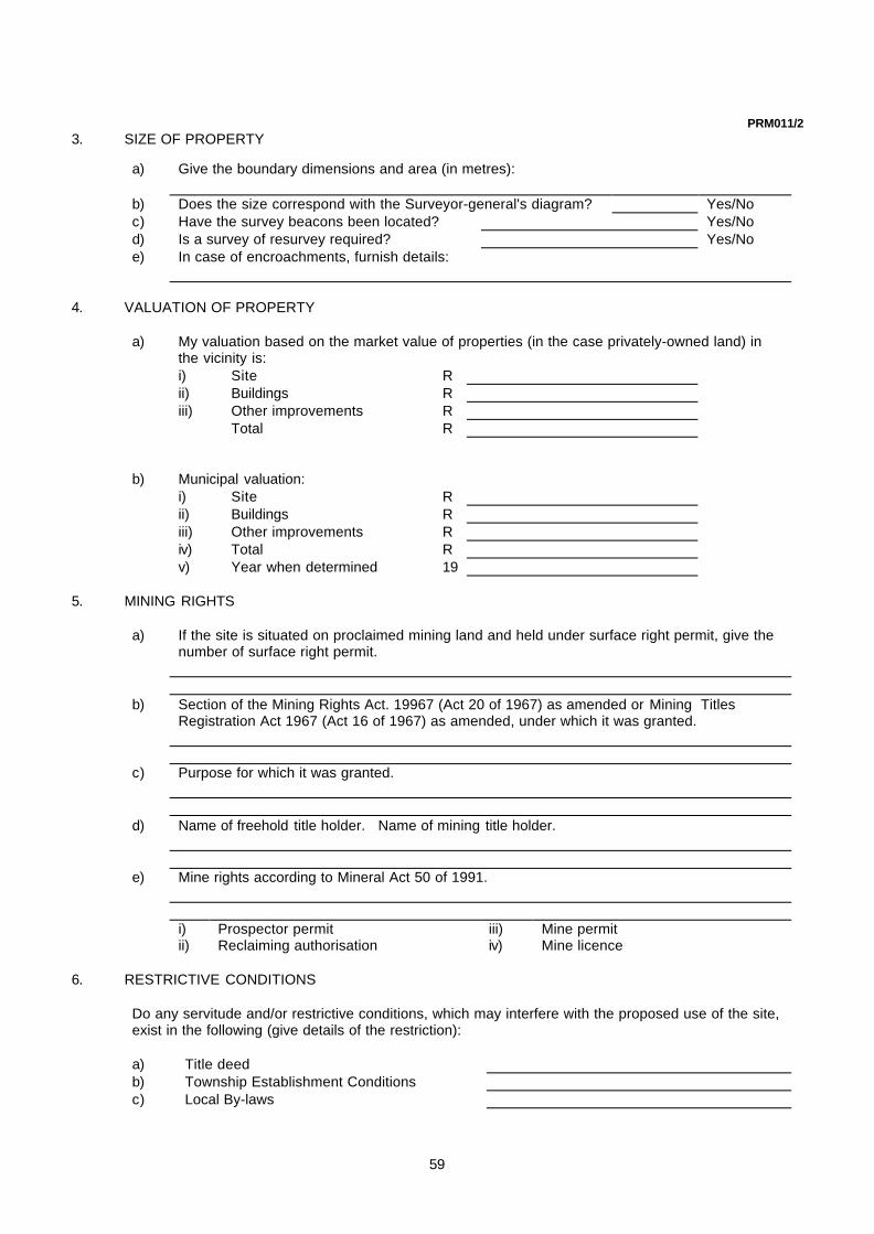
59
PRM011/23. SIZE OF PROPERTY
a) Give the boundary dimensions and area (in metres):
b) Does the size correspond with the Surveyor-general's diagram? Yes/Noc) Have the survey beacons been located? Yes/Nod) Is a survey of resurvey required? Yes/Noe) In case of encroachments, furnish details:
4. VALUATION OF PROPERTY
a) My valuation based on the market value of properties (in the case privately-owned land) inthe vicinity is:i) Site Rii) Buildings Riii) Other improvements R
Total R
b) Municipal valuation:i) Site Rii) Buildings Riii) Other improvements Riv) Total Rv) Year when determined 19
5. MINING RIGHTS
a) If the site is situated on proclaimed mining land and held under surface right permit, give thenumber of surface right permit.
b) Section of the Mining Rights Act. 19967 (Act 20 of 1967) as amended or Mining TitlesRegistration Act 1967 (Act 16 of 1967) as amended, under which it was granted.
c) Purpose for which it was granted.
d) Name of freehold title holder. Name of mining title holder.
e) Mine rights according to Mineral Act 50 of 1991.
i) Prospector permit iii) Mine permitii) Reclaiming authorisation iv) Mine licence
6. RESTRICTIVE CONDITIONS
Do any servitude and/or restrictive conditions, which may interfere with the proposed use of the site,exist in the following (give details of the restriction):
a) Title deedb) Township Establishment Conditionsc) Local By-laws

60
PRM011/3d) Local Town Planning Scheme
i) Zoning (residential, business etc.)ii) Building-line restrictioniii) Height restrictioniv) Densityv) Coveragevi) Any new roads or road widening
e) Provincial ordinances relating to roads and buildings
f) Advertising on Roads and Ribbon Development Act 1940 (Act 21 of 1940) as amended.
g) Abolition of Racially BASED Land Measures Act 1991 (Act 108 of 1991).
h) Abolition of Influx Control Act 1986 (Act 68 of 1986).
i) Physical Planning Act 1967 (Act 88 of 1967) as amended.
j) Mining regulations
k) Any other statutes applicable to the area (quote the Act or Ordinance).
l) Is the site subject to a lease agreement (if so, furnish conditions, particulars of lessee andwhether lessee is using the property for his purpose).
7. SITE PLAN
State whether the following information has been indicated on the site plan:
a) Boundary beacons, site dimensions and anglesb) Positions and dimensions of improvements (e.g. buildings, lenses, encroachments, etc.)c) Positions and dimensions of existing features (e.g. rock outcrops, furrows, etc.).d) Positions, diameters, heights and species (if known) of trees, hedges and shrubs.e) Any trees that are a danger to people and property, that must be removed.f) Distances to, positions and dimensions of adjoining property, roads, etc.g) Notes on the construction and finish of buildings on adjoining sites.h) North point.i) Building lines where set back from boundaries.j) Services (e.g. electrical supply, water supply, storm water pipes, sewer pipes, etc.)
Their dimensions and depths with recommendations about removing or diverting whereapplicable.
k) Positions of connections to services (e.g. water supply, electricity, etc.)l) Spot levels, floor levels, bench marks and contours (if possible)m) Position of trial holes, with detail sections.
n) Areas subject to flooring or marshy conditions during rains. (All negative replies shouldbe explained in a covering letter)
8. a) The following roads, streets, footpaths, drains, cables, power lines, water mains,furrows, etc. traverse the site.
b) These exist under the following authority:

61
PRM011/49. SITING
Give recommendations as to the siting of buildings with particular reference to the relative importance ofstreets bounding or adjoining the site, and adjoining property.
10. CLIMATIC CONDITIONS
a) Describe local climatic conditions whether in mist-, rain-, or snow belt direction of prevailingwinds and whether the temperature is subtropical or tropical.
b) Is the site in a Malaria area: Yes/Noc) Should fly/mosquito proofing be provided to the following:
i) Opening portions of all windows Yes/Noii) Verandas Yes/Noiii) All doors Yes/Noiv) Kitchen and pantry windows and doors only Yes/Nov) If not required, state reasons:
11. DESCRIPTION OF IMPROVEMENT
a) Give a brief description of the improvements with reference to the construction and finish ofroof, walls, floors and joinery.
b) Are floor plans/sketches of the improvements attached? Yes/Noc) Can these improvements be adapted? Yes/Nod) How can they be adapted? (Give details):
e) Estimated cost of alterationsi) Building Rii) Electrical Riii) Mechanical R
Total R
f) Are full appropriation drawings, foundation remeasurementplans and any other information available attached? Yes/No
g) Are photographs of the building showing main construction features, attached?Yes/No
h) In case where existing building on the site are to be demolished, should this:i) Be done departmentally? Yes/Noii) Be carried out under separate contract? Yes/Noiii) Be included in the main building? Yes/No

62
PRM011/5
iv) Are full appropriation drawings and a short Yes/Nodemolition specification attached? Yes/No
i) Is the site immediately available for building work? Yes/Noj) Is the whole site suitable for building work? Yes/No
12. FOUNDATION INFORMATION
a) Have trial hole samples been submitted to Head Office? Yes/Nob) Probable proportions of subsoil are as follows:
i) Hard rock %ii) Soft rock %iii) Earth %
c) Recommended depth of satisfactory foundations.
d) Should the foundations be reinforced? Yes/Noe) Should the ground under the building be treated with termite poison? Yes/Nof) Do buildings in the vicinity show signs of cracking? Yes/Nog) Is there any danger of sink holes in the area? Yes/No
13. BUILDING MATERIALS
Which of the following materials are available and recommended?
a) Type of face brick (e.g. A39, B20. etc.)State nearest source of supply.
b) Type of general purposes brick for foundations.c) Type of general purposes brick for superstructure.d) Nature of stone available suitable for concrete work? (e.g. mountain stone, granite,
freestone, etc.)
Distance to be transported.:e) Nature of sand available, suitable for concrete work?
Distance to be transported.:f) Nature of sand available, suitable for building and plaster work?
Distance to be transported.:g) Details of roof required, considering surrounding and climatic conditions (e.g. tiles,
galvanised iron, etc.).
h) Other materials used in the district for construction, state type.
14. FENCING
a) Is the site fenced or is there any other means of enclosure? Yes/Nob) If Yes/No, state whether the fencing:
i) Can be retained for future use. Yes/Noii) Can be repaired and re-used. Yes/Noiii) Can not be used. Yes/No
c) State details of fence if reusable (e.g. type, height size of gates, etc.).

63
PRM011/6
d) May the fencing on boundaries of adjoining sites be removed, if unsuitable for future use?Yes/No
N.B. Any new fencing required must be indicated on the site plan together with suitablepositions for entrance gates.
e) State type of fencing recommended. If not a standard type, give full details ofrecommended fencing
15. PROVISION OF SERVICES
Which of the following services are available? Yes/Noa) Local authority water
i) Cost of the following connections (if available)12mm R 37mm R18mm R 50mm R25mm R 75mm R100mm R
ii) Water pressure available at site boundaryiii) Is the water supply metered? Yes/No
DomesticFire FightingIrrigation
b) Bore hole water Yes/Noi) Depthii) Equipmentiii) Yield
c) Other source (perennial springs, rivers, tanks, etc.)
d) Local authority water borne sewer network: Yes/Noi) Are the position, depth, size and ground levels of existing sewers
indicated on the plan? Yes/Noii) If not state reasons.
iii) What is the cost of connection? R
e) Vacuum tank water borne sewerage system Yes/Noi) What is the minimum size of tank specified by the local authority?
ii) State number of removals per week.iii) State cost of removals R
f) Septic tank water borne sewerage system.i) Are septic tanks permitted? Yes/Noii) Are details of the standard absorbency test shown on site plan? Yes/No
g) Bucket removal or other system Yes/Noi) Description of system (pit chemical. etc.)
ii) State cost of system R

64
PRM011/7
iii) State number of weekly removals
h) Waste waterWhere soil conditions are unfavourable for the disposal of waste water, and there is nowater borne system, suggestions should be given for the disposal of waste water.
i) Stormwater disposali) Are positions, sizes, depths and levels of existing stormwaterpipes, channels,
culverts, in- and outlets indicated on the plan? Yes/Noii) Is the site traversed by any natural stormwater courses? Yes/Noiii) Is protection from natural run-off from higher lying areas
required? Yes/Noiv) State recommended method of stormwater disposal.
j) Fire servicei) Is a professional fire brigade available? Yes/Noii) What is the distance between the fire station and the site in kilometre?
iii) Are hydrants available? Yes/Noiv) Are the positions of the nearest hydrants indicated on the plan? Yes/Nov) In cases of additions, state number and positions of existing fire hose reels and/or
extinguishers.
vi) What size water supply is available for fire service? (Give cost of connection)75mm R 100mm R150mm R
vii) Average pressure of water supply for fire serviceviii) Will the local authority permit a combined fire and domestic water supply?
Yes/Noix) Does the local authority require the separate fire main to be metered?
Yes/Nok) Heating, lighting and cooking.
NB (i), (ii) and (iii) must be completed by the electrical consultant.i) Is an electricity supply available? Yes/No
(If yes, from OW300, must be submitted as well).ii) If not, when will it be available?iii) If not, state proposed method of lighting etc.
iv) What fuel is recommended for cooking?
v) What fuel is recommended for heating?
l) Public transport.i) Name of nearest railway station.ii) Distance from station to site.

65
PRM011/8
16. GENERAL
PRINCIPAL AGENT DATE
EXPLANATORY NOTES
NOTE : i) Full details are to be furnished with a view to facilitating the preparation ofworking drawings.
ii) A detailed site plan together with photographs which illustrate the site'sfeatures as well as photographs from the site in all directions to show the outlook, must besubmitted with this form.
iii) A locally plan/sketch should also be submitted.
iv) The form, photographs, plans and other relevant information must besubmitted in triplicate to Head Office.
v) Attach a loose sheet of paper for all items where the space is insufficientwith the necessary cross referencing.
vi) The following notes should be carefully read:
Trial Holes and Foundations
The officer must view the trial holes and check levels before particulars are submitted to Head Office. All trial holesother than those where rock is encountered, are to be excavated to a depth of three metres at least, even if gravelor shale formations are encountered, as these formations often occur in a thin layer with doubtful material below. Afull description of each trial hole is to be submitted to Head Office, detailing the thickness of the formations cutthrough, to the full depth of trial holes. The average depth to approved bottom is also to be given. Samples of theformations cut through in sequence from the top to bottom of holes are to be submitted to Head Office, givingdescriptions and thicknesses.
Accurate particulars and levels are essential as it is on this information that foundations, surface and soil drainage,and other factors are determined.
Works on Site and Demolitions
The short specification submitted for the demolition of existing buildings, when such demolitions are to be includedin the main building contract, must include a description of the materials of which the foundations, superstructure,roof, floors, ceilings, windows, etc., are constructed. In addition the overall dimensions of the buildings must begiven. In the most cases those dimensions will appear on the appropriation drawings but if such drawings are notavailable or dimensions are not given thereon, then they must be given separately.State whether any of the old materials or fitting should be handed over to the Department. Describe such materialsand state where they should be handed over (i.e. on site, at P.W. and LA Store, etc.) Also give full particulars ofany materials or fittings considered serviceable and suitable for re-use in a new building.

66
PRM011/9When furrows are to be filled in, or any other such work is to be done on the site, give the length, width and depthof such furrows or word.
When walls and similar structure have to be pulled down, give their length, height and thickness and state thematerials of which they are constructed.
When earth, stone or other surplus materials debris have to be removed from the site, and estimated amount incubic metres should be stated.
Alterations and Additions to Existing Buildings.
State whether any of the old materials or fitting should be handed over to the Department. Describe such materialsand state where they should be handed over (i.e. on site, at P.W. and LA Store, etc.) Also give full particulars ofany materials or fittings considered serviceable and suitable for re-use in a new building.
When furrows are to be filled in, or any other such work is to be done on the site, give the length, width and depthof such furrows or word.
When walls and similar structure have to be pulled down, give their length, height and thickness and state thematerials of which they are constructed.
When earth, stone or other surplus materials debris have to be removed from the site, and estimated amount incubic metres should be stated.
Alterations and Additions to Existing Buildings.
Comprehensive and explicit information must be furnished in this respect. In addition to appropriation drawings.Remeasurement of Foundation plan and photographs, full information must also be submitted in regard to thematerials of which the walls, floors, ceiling, windows, roof covering, caves, gutters, rainwater pipes etc., areconstructed. The interior and exterior finishing, especially of those portions of the buildings that will be afflicted bythe alterations and/or additions, must be specified.
Particulars of drains, water supply, fire, lighting and other services must be furnished.
Fencing:
It is recommended that the existing fencing should be repaired and re-used, a full description of the fence shouldbe given. State the materials of which the fence is constructed, the number of wires, the distance between posts,the number of standards and droppers and the estimate amount of material required to repair the fence.

67
ANNEXURE C
DRAWING TITLE BLOCK
The Drawing Title Block can be obtained from the Chief Architect:Project Manager Advisory Services: Architectural
Central Government Offices: Pretoria

68
EDIT
EDIT
EDIT
EDIT
EDIT
Director-General:
consultant/departmental
discipline
service
drawing title
ref.no designed
scale drawn
date checked
type number
drawing number
cad file name
Copyright vests in the
Department of Public Works
D.P.W.AMENDMENTDATENO.
WCS number

69
ANNEXURE D
SKETCHPLAN CHECK LIST
PRM 017
The Coat of Arms can be obtained from Chief of Architect:Project Manager Advisory Services: Architectural
Central Government Offices: Pretoria

70
PRM017/1
DEPARTMENT OF PUBLIC WORKS SKETCH PLAN CHECK LIST
PROJECT: WCS NO :
REFERENCE NO:
To be completed by the Private ArchitectIndicate in box next to EACH item whether provided or not applicable
1. SITE PLAN 3. ACCOMMODATION1.1 Site dimension.............................................. 3.1 Comparative schedule of rooms required1.2 Building line setbacks................................... and provided with areas................................................ 1.3 Contours at suitable intervals and spot 4. ELEVATIONS
levels of pavements and floors .............................. 4.1 General architectural treatment ................................... 1.4 North point ..................................................... 4.2 Principal materials .......................................................1.5 Prevailing winds ............................................. 5. SECTIONS1.6 Street names ................................................. ____ 5.1 Dimensioned floor to floor and floor to ceiling1.7 Type of existing and proposed- heights......................................................................... 1.7.1 boundary fences, walls and gates......... 5.2 Floor levels and adjacent natural and formed
1.7.2 retaining walls........................................ ground levels, showing excavation and filling.............. 1.8 Existing buildings on adjoining sites likely 5.3 Roof slopes and type of construction and1.9 to affect the design of new buildings............... Consideration given to-covering...................................
1.9.1 rights of adjoining owners...................... 5.4 Material and finish of walls...........................................1.9.2 need for lateral support, etc.................... 6. CONSULTATIONS : Has the scheme been
1.10 Existing buildings on site to be - discussed with :1.10.1 retained ................................................ 6.1 Specialist Department...................................................
1 .10.2 demolished............................................. 6.2 User Department...........................................................1.11 Trees to be removed or retained...................... 6.3 Divisional Engineer, Telkom, for telephone1.12 Natural water courses with flood lines and requirements..................................................................
levels............................................................ 6.4 Local Authority for -1.13 Servitudes and Departmentally owned services..........................................................................
service mains which - town-planning requirements...........................................1.13.1 cannot be disturbed.......................... 6.5 Quantity Surveyor for costs............................................1.13.2 need to be diverted........................... Consultant and/or Departmental Specialist
1.14 New buildings............................................... 6.6 Structural........................................................................1.15 Site terracing, with treatment of banks ........ 6.7 Civil Works for -1.16 Site terracing, with treatment of banks- roads, drainage and stormwater.......................................
grassed, stone pitched, concrete retaining 6.8 Mechanical, for -walls, etc. .................................................... fire service........................................................................
1.17 Roads, paths and paving with finishes- heating, ventilating, and air-conditioninggravel, tarmac, concrete etc. ...................... mechanical plant/equipment............................................
1.18 Positions and depths of connection points 6.9 Electrical Emergency Generators for lifts........................ of sewer, stormwater drain, water and fire 6.10 Chemical Technology: Process design of waterservice.......................................................... and sewerage treatment facilities....................................
2. BUILDING PLANS 7. GENERAL2.1 Overall dimensions of new work.................. 7.1 Any other information likely to affect the2.2 Treatment at junction of new and old work.. Estimate (state) (Items 1 to 6):2.3 Structural column grid.................................. .................................................................................................2.4 Room dimensions and areas (toilets .................................................................................................
excepted) and corridor widths...................... .................................................................................................2.5 Engineering service rooms and ducts.......... .................................................................................................2.6 Position of s anitary and other fittings........... .................................................................................................2.7 Floor finishes................................................ .................................................................................................

71
PRM017/2
8. CERTIFICATE BY PRIVATE ARCHITECTThe Department's instructions given in the letter of appointment, the "Architects' Manual", withannexures, and the items on this Check List and the "Schedule of Construction and Finishes, etc."have been studied by me/us and, where applicable, complied with items which have not beencomplied with, or for which alternative proposals are made, are as follows :
PRIVATE ARCHITECT / PRINCIPAL AGENT DATE
9. APPROVAL BY DEPARTMENTAL PROJECT MANAGER:
PROJECT MANAGER DATE
10. REMARKS BY CLIENT / USER:
CLIENT/USER REPRESENTATIVE DATE

72
ANNEXURE E
SCHEDULE OF CONSTRUCTION AND FINISHES,
USE FACTOR ANALYSIS AND ESTIMATE
PRM 018

73
PRM018DEPARTMENT OF PUBLIC WORKS
SCHEDULE OF CONSTRUCTION AND FINISHES, USE FACTORANALYSIS AND ESTIMATE
PROJECT : WCS NO:REFERENCE NO:
This form is to be completed by the private Architect in every detail and submitted with the Sketch Plan and Sketch Plan CheckList. Indicate applicable items by marking the appropriate line:-
1. FOUNDATIONS 5. WINDOWS1.1 FOOTINGS TYPE : POSITION :1.1.1 Conventional unreinforced concrete 5.1 Steel, painted..............................................................
strip...................................................... 5.2 Steel, galvanized.........................................................1.1.2 Reinforced concrete............................. 5.3 Aluminium, untreated..................................................1.1.3 Foundation beams and piles average 5.4 Aluminium anodized....................................................
length..................................metres...... 5.5 Other (specify on separate sheet)............................... 6. CEILING TREATMENT
1.2 FOUNDATION WALLING TYPE : POSITION :1.2.1 Brickwork (not reinforced).................... 6.1 Gypsum or fibreboard on brandering..........................1.2.2 Reinforced brick................................... 6.2 Plaster on concrete.....................................................1.2.3 Reinforced concrete............................. 6.3 Suspended under concrete.........................................1.2.4 Other (describe on separate sheet). 6.4 Acoustic panels...........................................................
6.5 Other (specify on separate sheet)............................... 1.3 FINISH 7. FLOOR FINISH
TYPE : ...............................POSITION: ..............1.3.1 Face brick............................................ 7.1 Vinyl asbestos tiles......................................................1.3.2 Plaster and paint.................................. 7.2 Granolithic...................................................................1.3.3 Precast terrazzo................................... 7.3 Ceramic.......................................................................1.3.4 Other (describe on separate sheet)..... 7.4 Wood Mosaic..............................................................
7.5 Concrete paving..........................................................2. SUPER STRUCTURE 7.6 Other (specify on s eparate sheet)..............................2.1 Load bearing brickwork................................. 8. EXTERNAL SUN PROTECTION2.2 Reinforced concrete frame............................ Required? (Described on separate sheet)..................2.3 Structural steel frame.................................... 9. SPECIAL GLAZING2.4 Beam and panel slab floors.......................... Required? (Describe on separate sheet)....................2.5 Other (describe on separate sheet).............. 10. USE FACTOR ANALYSIS3. EXTERNAL WALLING SYSTEM Total area of building, all floors but exluding basement
TYPE : POSITION : .....................square metres3.1 Brick with the following facings: Total net usable area. excluding corridors, foyers3.1.1 Face brickwork..................................... toilets. engineering service rooms ............square metres3.1.2 Plaster and paint.................................. Usable area expressed as a percentage of the total area3.1.3 Precast terrazzo................................... ........................................................................................3.1.4 Other (describe on separate sheet) 11. ESTIMATE4. INTERNAL WALLING SYSTEM All inclusive estimate of cost of service excluding -VAT4.1 Brick, plaster and paint.................................. R..................................................................................4.2 Other (describe on separate sheet)..............
_________________________________________________________________________________________Note: Describe on a separate sheet any additional features likely to affect the estimate. If necessary,also elaborate in like manner on any items appearing on this sheet, quoting the relevant referencenumbers
PRIVATE ARCHITECT PRINCIPAL AGENT
DATE DATE
ANNEXURE F

74
BUILDING ECONOMY: CATEGORISATION OF BUILDINGS
1. Upon allocation, each service is placed in one of four categories:
A. Prestige buildings, such as Supreme Courts, offices and residences for members of the Government, theDiplomatic corps and other highly placed officials, and buildings of special national importance or aestheticsignificance such as National Monuments.
B. The bulk of the State loan vote building programme comprising offices: magistrate's courts; police divisionaland district headquarters, stations and quarters; hospitals and nurses' homes; schools: agricultural researchstations: buildings for the Departments of Defence and Prisons, and the like.
C. Minor buildings connected with those in Category B and certain buildings in smaller centres.
D. Utility buildings such as factories, garages and stores.
2. Attached is a list of components, materials and finishes of the maximum standards which may be used foreach category. These are to be regarded as a general guide and other articles in equivalent cost bracketswill be admissible subject to the Department's approval on grounds of suitability.
3. Exceptions to the standard lists will be allowed for the following reasons;
3.1 Buildings such as research establishments, laboratories, hospitals and the like, in respect of those areasof such buildings where special finishes are required by the Client Department. Such exceptions must beauthorised by the Department of Public Works in each individual case.
Some examples of special provisions under this heading are as follows:
Encaustic tiles to floors (for acid resistance).
Note: - No type of special glass may be used in any case unless specifically authorised by the DepartmentExamples of such special glass are as follows:Glazing with 7,5 mm high impact glass (for security).Glazing with 9,5 mm high impact glass (for security).Bullet-resisting glass.
3.2 Besides the above special finishes, where finishes from a higher category may be necessary for buildingsin a lower category to satisfy practical requirements. The Architect will be given specific instructions insuch cases.
3.3 Specific requirements of Local Authorities, e.g. for roofs, where sheet materials may not be permitted andslates or tiles may be required. Such requirements must be brought to the notice of the Department andmust be compiled with unless the Department gives written directions to the contrary.
3.4 Buildings in coastal areas, in respect of materials required to combat corrosion. Examples of suchmaterials are listed below: in each category the materials are given in order of cost, with the cheapest first.
Roofs:
Corrugated asbestos.Tiles (concrete or clay),where approved by the Department, generally for aesthetic reasons or statutory requirements.
Windows:
Hot dip galvanised steel.Aluminium or wood,where approved by the Department, generally for aesthetic reasons.
External doors and gates:
Wood, painted.Hardwood, where approved by the Department.
Fencing:
Aluminium wire mesh.Precast concrete walling.Brick walling, where approved by the Department.

75
Rainwater goods:
Fibre -cementP.v.c, where available sizes are adequate.Copper, where approved by the Department.
Flashings:
Aluminium.Copper where approved by the Department.
3.5 Where other physical conditions require special provisions e.g.:
3.5.1 Where the nature of the soil or water would cause corrosion of galvanised iron supply and servicepipes,nessecessitating the use of alternative materials such as p.v.c or copper.
3.5.2 For acoustical correction, where appropriate ceiling, wall and floor finishes are necessary.
4.CATEGORY A: PRESTIGE BUILDINGS AND NATIONAL MONUMENTS
No restrictions subject to the exercise of reasonable economy. Some of the items the use of which islimited to Category A are as below:Marble flooring.Wall to wall carpeting to Court-rooms, prestige offices and elsewhere where approved by theDepartment.Glazed wall tiling, coloured.Wall panelling, blockboard (by special approval).Wall panelling, moulded (by special approval).Purpose made hardwood doors.Hardwood windows.
5. CATEGORY B: MAJORITY OF BUILDINGS
Maximum Standards
Roofs:
Corrugated iron, including timber roof construction.Rib trough, long span, including timber roof construction.Fibre cement sheeting, including timber roof construction.Fibre cement slates, including timber roof construction.Cement tiles, including timber roof construction.Clay tiles, including timber roof construction.Concrete flat roof including slab, screed and waterproofing membrane (only where approved by theDepartment).
Ceilings:
Fibre cement or gypsum board, including brandering.Fibrous plaster board, including brandering.
The following only for the purposes stated:
Gypsum suspended ceilings, including galvanised steel (only where necessary to conceal service).Acoustic ceilings on brandering (where necessary for acoustical correction).Acoustic suspended ceilings (only where necessary for acoustical correction including reduction ofheight and for accommodation of services).
Note - Concrete slab ceilings are to be skim coated except in store rooms, etc. where off-shuttershould be specified.
Floors:
Floated finish on concrete.Granolithic cement.2,0 mm Vinyl asbestos tiles.2,0 mm Vinyl tiles.2,0 mm Vinyl sheet.Terrazzo tiles.

76
Ceramic tiles.Strip flooring, S A pine, including joists (indoor sport facilities, stages).
Wall finishing:
Bagging.One coat compo plaster.One coat cement plaster.Two coat plaster.
Hard finishes: polyurethane stippled and / or glazed coatings.
Face brick (internal)Vinyl sheeting.Glazed tiling, white.
Doors:
F L & B boarded one face, plywood the other.Hollow core.Semi-solid core.Solid core.Solid laminated and veneered.
Windows:
Steel, stock industrial.Steel, stock residential.Steel, residential, purpose made.Aluminium stock.Aluminium, purpose made.
Glazing:
Clear float glass of require thickness in windows.6 mm Laminated safety glass in doors and low windows or sidelights and where necessary for safetyand security reasons.
Painting:
Cement wash.Emulsion paint.Enamel.
6. CATEGORY C: MINOR BUILDINGS
Maximum Standards
Roofs:
Corrugated iron, including timber roof construction.Rib trough, long span, including timber roof construction.Fibre cement sheeting, including timber roof construction.Concrete flat roof, including slab, screed and waterproofing membrane (only where approved by theDepartment).
Ceilings:
Fibre cement or gypsum board, including brandering.Acoustic ceiling on brandering (only where necessary for acoustical correction).
Note: Wherever possible, soffits of concrete slabs are to be left off-shuttering, e.g. in basements, stores,strong rooms, cells, workshops, covered ways etc.; elsewhere to be skim coated.
Floors:
Floated finish on concrete.Granolithic cement.Vinyl asbestos tiles.Terrazzo tiles.

77
Wall finishing:
Bagging.One coat compo plaster.One coat cement plaster.Hard finishes: polyurethane stippled and / or glazed coatings.Face brick (internal).
Doors:
F.L. & B., boarded one face, plywood the other.Hollow core.Semi-solid core.
Windows:
Steel, stock industrial.Steel, stock residential.Steel, residential purpose made.Aluminium stock.
Glazing:
Clear float, glass of required thickness in windows.
Painting:
Cement wash.Emulsion paint.Enamel.
7. CATEGORY D: UTILITY BUILDINGS
Maximum Standards
Roofs:
Corrugated iron, including timber roof construction.Rib trough, long span, including timber roof construction.
Fibre cement sheeting, including timber roof construction. Concrete flat roof, including slab, screed and waterproofing membrane (only where approved by the
Department).
Ceilings:
Fibre cement or gypsum board, including brandering.
Note: Wherever possible, soffits of concrete slabs are to be left off-shuttering, e.g. in basements, st stores, strong rooms, cells, workshops, covered ways etc.
Floors:
Floated finish on concrete. Granolithic cement. Vinyl asbestos tiles.
Wall finishing:
Bagging. One coat compo plaster. One coat cement plaster. Hard finishes: polyurethane stippled and / or glazed coatings. Face brick (interna
Doors:
F.L. & B., boarded one face, plywood the other. Hollow core. Semi-solid core.

78
ANNEXURE G
CODE NUMBERS OF TYPE DRAWINGS
1. FUR Furniture
2. GEN General
3. JUS Justice
4. POL Police
5. PRI Prisons
6. SB State Housing
Note: - In Category 6 drawings of married and single quarters for all ranks, comprising houses, outbuildings, maisonettes and flats are available if required.
FURNITURE
NO DRAWING REMARKS
FUR 011 Standard Office Furniture Desk Type 1 – Typist (1 500 x 700)
FUR 002 Standard Office Furniture Desk Type 2 - (1 500 x 900)
FUR 003 Standard Office Furniture Desk Type 3 - (1 800 x 900)
FUR 004 Standard Office Furniture Desk Type 4 (1 500 x 700)
FUR 005 Standard Office Furniture Desk Type 5 - Data Typist
FUR 006 Standard Office Furniture Correspondence Rack
FUR 007 Standard Office Furniture Book Cupboard
FUR 008 Standard Office Furniture Easy Chair
FUR 009 Standard Office Furniture Coffee Table
FUR 101 Standard Office Furniture Bookcase with glass doors
FUR 011 Standard Office Furniture Book Cupboard (858 mm high)
FUR 012 Standard Office Furniture Map Table
FUR 013 Standard Office Furniture Telephone Table (replaces dwg No 10142/6/M)
FUR 014 Standard Office Furniture Stationary Cabinet (replaces dwg No. 10142/25/M)
FUR 015 Standard Office Furniture Pigeon Hole Fitting (30 Pigeon Holes) (replaces dwg No 10142/30)
FUR 016 Standard Office Furniture Pigeon Hole Fitting (replaces dwg. No 10142/31)
FUR 017 Standard Office Furniture Office Stool (replaces dwg. No 10142/32)
FUR 018 Standard Office Furniture Settee for Rest Room (replace dwg No. 10142/36)
FUR 019 Standard Office Furniture Bench (replaces dwg. No 10142/51/M)
FUR 020 Standard Office Furniture Pedestal Table (replaces catalogue No. A3186/5)
FUR 021 Standard Office Furniture Cumberland Chair for Judge
FUR 022 Standard Office Furniture Cumberland chair
FUR 023 Standard Office Furniture Conference Table
FUR 024 Standard Office Furniture Utility Table

79
NO DRAWING REMARKS
FUR 025 Standard Office Furniture Steel Office Chair
FUR 026 Standard Office Furniture Desk Type 6
FUR 028 Standard Office Furniture Hat Rack
FUR 029 Standard Office Furniture Telephone Shelf

80
GENERAL
NO DRAWING REMARKS
GEN 001N 3 Chamber Substation (one transformer) Consult Electrical Branch for requirements
GEN 002 Type single store for flammable liquids Consult Fire Protection Officer
GEN 003 Prison type security fences and gates Consult Chief Architect if gumpoles are to besubstituted by mild steel posts
GEN 004 Security fences and gates Consult Chief Architect if gumpoles are to besubstituted by mild steel posts
GEN 005N 3 Chamber Substation with emergency Consult Electrical Branch for requirementsengine room (NORMAL)
GEN 006N Type Substation for 2 transformers Consult Electrical Branch for requirements(NORMAL)
GEN 007 Standard methods of lighting protection Consult Electrical Branch for requirements
GEN 008M 3 Chamber Substation with emergency Consult Electrical Branch for requirementsroom. (MIRRORED of GEN 005)
GEN 009M 3 Chamber Substation (one transformer) Consult Electrical Branch for requirements(MIRRORED of GEN 001)
GEN 010 Type garages (covered) (Note: Alternative type roof for coastal area)
GEN 011N Standard Substation. (NORMAL) Consult Electrical Branch for requirements(7,560 x 3,040)
GEN 012M Standard Substation. MIRRORED of Consult Electrical Branch for requirementsGEN 011
GEN 013 Type aluminium flagstaff Normal type
GEN 014/1 Timber trusses double pitch Consult Structural Branch
GEN 014/2 Timber trusses single pitch A1
GEN 014/3 Timber bracing A1
GEN 015M Type Substation for 2 transformers. Consult Electrical Branch for requirements(MIRRORED of GEN 006)
GEN 016N 2 Chamber Substation (one transformer) Consult Electrical Branch for requirements
GEN 017M 2 Chamber Substation (one transformer) Consult Electrical Branch for requirements(MIRRORED of GEN 016)
GEN 018N Combination (NORMAL) Consult Electrical Branch for requirements
GEN 019M Combination mains and standby plant Consult Electrical Branch for requirementsSubstation (MIRRORED of GEN 018N)
GEN 020/1 Type plant rooms: up to 20 KVA Consult Electrical Branch for requirements
GEN 020/2 Type plant room: 20kVA up to 80 kVA
GEN 021/1 Type plant room: 80 kVA up to 250 Consult Electrical Branch for requirementskVA
GEN 021/2 Type plant room: For two sets
GEN 022 Barrier Boom Consult Co-ordinating Architect
GEN 023 Type Substation (6,250 x 4,810) Consult Electrical Branch for requirements
GEN 024 Heavy type aluminium flagstaff Heavy type suitable on buildings
GEN 025 Magazine Type “E” Consult QME (Police) for suitability etc. Seealso Structural Drawing No S6839/1 forreinforcement details
GEN 026 Type covered parking with bracing(Rafters at 2,5m centres)
GEN 026A Type covered parking with bracing(Rafters at 2,5m centres)

81
NO DRAWING REMARKS
GEN 027 Type lettering for State buildings Consult Co-ordinating Architect
GEN 028 Conference table This drawing supersedes Drawing No 13274/M
GEN 029 Pistol range Consult Police Training Department
GEN 030 Double store for flammable liquids Consult FPO
GEN 030/A Double store for flammable liquids Consult FPO
GEN 031 Galleries for spherical and hemi- Consult Electrical Branch for requirementsspherical bowl fittings
GEN 032 Chart of Departmental organisation Consult Electrical Branch for requirements
GEN 033 Type locker for Magistrate’s gown Consult Co-ordinating Architect
GEN 034/1-6 Type motor transport servicing ramp for Consult Co-ordinating Architect
GEN 034/1 General plan and Elevations
GEN 034/2 Details of Type A
GEN 034/3 Details of Type B
GEN 034/4 Details of Type C
GEN 034/5 Details of Type D
GEN 034/6 Details of Type E
GEN 035/1 Type office furniture PWD details Superseded in 1984 by type FUR 001 - 005
GEN 035/2 Full scale details for desk Superseded in 1984 by type FUR 001 - 005
GEN 036 Rack unit, book rack, telephone cabinet Superseded in June 1984 by type FUR 006-007
GEN 037 Stinkwood casket for presentation key
GEN 038 DPC at ground level in foundation wall at A4 sheet sizeconcrete bed for 270 mm walls
GEN 039 Method of folding drawings (A1-sheet A4 sheet size594 x 841)
GEN 040 Method of folding drawings (A0)-sheet A4 sheet841 x 1180)
GEN 041N 3 Chamber Substation (14,260 m long)(one transformer)
GEN 042 Type shower A4 sheet
GEN 043 Security observation window A4 sheet size
GEN 043A Security communication window A4 sheet size
GEN 044 Security Communication window A4 sheet size
GEN 045 Security Communication window A4 sheet size
GEN 046 Security steel door
GEN 047 Type agricultural implements store
GEN 047/1 Plan, elevations, sections
GEN 047/2 Door schedule
GEN 047/3 Window schedule
GEN 048A Flagstaff to height 2450 (free-standing)

82
NO DRAWING REMARKS
GEN 048B Flagstaff to height 2100 (free-standing)
GEN 048C Type flagstaff for court-rooms(fixed to wall)
GEN 049 Type ironing boardGEN 050 Structure diagram of posts of the Chief
Directorate Architecture
GEN 051 Folding Method of Drawing (A1) A4 sheet sizeGEN 052 Folding Method of Drawing (AO)
GEN 053 Standard Mass Concrete Footings
GEN 054 Typical Eaves Detail A4 sheet size
GEN 055/1-4 Standard Toilet for Disabled Persons A4 sheet size(High Level Cistern)
GEN057/1-4 Standard Toilet for Disabled Persons A4 sheet size(Flush Valve)
GEN 059 Standards for the Planning of Messesand Recreation Facilities: Billiard Room A4 sheet size
GEN 060 Type Double Garage
GEN 061/02 Details, Notes & Schedules Ref 6048/0133/8/4A/15(60 Man Dormitory)
GEN 061/01 Plan, Elevations Sections & details Ref 6048/0133/8/4A/15(60 Man Dormitory)
GEN 063 Type Name Board A3 sheet size
GEN 066 Typical stoep screen & gate

83
JUSTICE
NO DRAWING REMARKS
JUS 001/1 Furniture Layout and Sections Consult Co-ordinating Architect
JUS 001/2 Magistrate’s Bench
JUS 001/3 Table 1500 x 750
JUS 001/4 Table with lectern
JUS 001/5 Table 1500 x 750 – cupboard
JUS 001/6 Table 750 x 750 – cupboard
JUS 001/7 Barrier
JUS 001/8 Public Benches
JUS 001/9 Dock
JUS 001/10 Witness box and Recording cabinet
JUS 001/11 Type Locker for Magistrate’s Gowns
JUS 001/12 Emblem for Department of Justice

84
POLICE
NO DRAWING REMARKS
POL 001/1-9 Cell layout and details Consulting Co-ordinating Architect
POL 005 Type pistol and rifle racks for police Consulting Co-ordinating Architectstation
POL 006N Type 1 Mortuary for 250 bodies. NORMAL Consulting Co-ordinating Architect
POL 007N Type 2 Mortuary for 300 bodies. NORMAL Consulting Co-ordinating Architect
POL 008N Type 3 Mortuary for 600 bodies. NORMAL Consulting Co-ordinating Architect
POL 009M Type 1 Mortuary for 150 bodies. MIRRORED Consulting Co-ordinating Architect
POL 010M Type 2 Mortuary for 300 bodies. MIRRORED Consulting Co-ordinating Architect
POL 011M Type 3 Mortuary for 600 bodies. MIRRORED Consulting Co-ordinating Architect
POL 012 Type Mortuary Type “S” (attached to a building) Consulting Co-ordinating Architect
POL 013 Police Emblem (Full size)
POL 014 Guard Hut Type A
POL 014A Guard Hut Type A - Drainage only
POL 014B Control Post Cate Opening Mechanism
POL 015 Security Fence and Gates and Windowprotection for SAP and premises
POL 015A Security Fence (Inland Areas) for S A Policestations and premises
POL 015B Security Fence (Coastal Areas) for S A Policestations and premises
POL 016 Rack for 4-37mm Anti-riot Rifle and 12cartridge bags
POL 017 Bicycle hook, benches in cells and screen wallnext to w.c. in cell
POL 018 Elevation and plan of partitioning betweenCharge Office and Detention Area
POL 019 Section and isometric of drink fountain, w.c.pan and wash hand basin

85
PRISONS
NO DRAWING REMARKS
PRI 014 Prison type Maisonettes(3 bedrooms and outbuildings)
PRI 015 Type Double bed and Single bed
PRI 016 Type L-flats 2 Storeys: 4 flats ± 76,3 m² flat
PRI016R Type L-flats 2 Storeys: 4 flats ± 76,3m² flat
PRI 017 Type 3L-flats 3 storeys: 6 flats ± 79,5m² flat
PRI 017R Type 3L-flats 3 storeys: 6 flats ± 79,5m² flat
PRI 018 Type 5L-flats 2 & 3 storeys staggered:5 flats 78,3m² flat
PRI 019 Type 2m - flats 2 storeys: 4 flats ± 86m² flat,staircase in vertical position
PRI 020 Type SM-flats 2 Storeys: 4 flats ± 86m² flatstaircase in horizontal position
PRI 021R Type 3M/R flats 3 Storeys: 6 flats ± 89,2m² flat
PRI 022 Type prison window

86
ANNEXURE H
(Paragraph C.2.5.2 refers)
USE OF PREFABRICATED MULTI-NAIL TRUSSES
1. In all cases conventional bolted trusses are specified in the original documentation, but if theContractor proposes the use of multi-nail trusses as an alternative, he must first offer a substantialsaving in cost and until this has been approved the substitution of trusses of this type will not beconsidered.
2. The use of the prefabricated multi-nail timber roof trusses is subject to the approval of the ProjectManager.
3. The Contractor is required to submit to you in good time, for forwarding to the Project Manager, an A1size polyester print of 0,05 mm minimum thickness of a drawing signed by a Registered ProfessionalEngineer who is on the Department’s panel for structural work, which shows the following information:
3.1 The type of roof covering and design loads, maximum purlin and brandering spacing, which must be inaccordance with the Standard Specification.
3.2 Complete details of the roof system, showing the positions of the trusses and purlins and typicalelevations. The minimum bracing must comply with the recommendations of the Truss PlateAssociation. Truss angles or apex heights must be indicated.
3.3 Sizes and grades of all timber members.
3.4 Plate sizes for each connection to enable a thorough check to be made on Site; code numbers are notacceptable. Connections for hip, valley and jack trusses, etc., must be separately detailed.
4. Before the Contractor is authorised to proceed with the supply of multi-nail trusses, you must obtaininformation of approval from the Project Manager in writing.
5. To avoid any problems in this connection, the Contractor should be advised of the above conditions atthe time of handing over of the Site.
Arc Man Doc PW147 (Hans