Embed Size (px)
Citation preview
DEMO 5:HVDC Superconducting Link
Christian-Eric BRUZEK(Nexans France)
“INNOVATIVE NETWORK TECHNOLOGIES AND THE FUTURE OF EUROPE'S ELECTRICITY GRID”
BEST PATHS DISSEMINATION WORKSHOP
BERLIN, 26 OCTOBER 2016

Normal metal
R (W)
T (K)
R > 0
T = 0 K -273°CAbsolute zero
What is superconductivity?
Superconductors = almost perfect conductors of electricity:no electrical resistance!
Best Paths Dissemination Workshop - Demo 5 - Berlin 26/10/2016
2
Superconductor
TcCritical temperature
R 0Superconducting state
Magnetic field
Current density
Temperature
Tc
Jc
Bc
Superconducting domain
Superconducting materials have a huge current rating: at least 150 times greater than copper for HTS materials!
Superconducting cables provide a new way to solve power transmission (voltage x current) issues by increasing the current (up to 5 kA AC or beyond 20 kA DC) rather than the voltage

Requirement of cooling at very low temperatures
Best Paths Dissemination Workshop - Demo 5 - Berlin 26/10/2016
3
Temperature (K)
Timeline of discovery
T = 0 K -273°CAbsolute Zero
(lowest temperature that canbe reached in the universe)
T = 200 K -73°C
Extreme cold
Industrial cooling
Ambient temperature
T = 0°C 273 K(water becomes ice)
Liquid helium
Liquid hydrogen
Liquid nitrogen
Cryogenic fluids
Superconducting materials
HTS cuprates
MgB2
-200°C
-250°C
(or helium gas @20 K / 20 bar)

How to transmit bulk power 3-5 GW? (examples of corridors)
Best Paths Dissemination Workshop - Demo 5 - Berlin 26/10/2016
4
15.5 m
Clearing width 45 m
Right-Of-Way width 66 m
47 m
34 m
8 m
Nelson River DC line (Canada)1600+1800 MVA (+2000 under construction)
Geneva, Palexpo Link 2001,
470 m, 220 kV / 2 x 760 MW
Frankfurt Airport,
Kelsterbach Link 2012,
900 m, 400 kV / 2 x 2255 MW
Raesfeld (380 kV AC, Germany)2x 1800 MW
Overhead linesGas insulated lines
XLPE cables

Main objectives of the superconducting demonstrator
10 partners to demonstrate the following objectives
• Demonstrate full-scale 3 GW class HVDC superconducting cable systemoperating at 320 kV and 10 kA
• Validate the novel MgB2 superconductor for high-power electricity transfer
• Provide guidance on technical aspects, economic viability, andenvironmental impact of this innovative technology
Best Paths Dissemination Workshop - Demo 5 - Berlin 26/10/2016
5
System integration pathways for
HDVC applications
Investigation in the availability of the
cable system
Preparation of the possible use of H2
liquid for long length power links
Cable and termination
development+ manufacturing
processes
Validation of cable operations with
laboratory experiments performed in He gas at variable temperature
Operating demonstration of a
full scale cable system transferring
up to 3.2 GW
Process development to manufacture a
large quantity of high performance MgB2
wires at low cost

10 project partners for an outstanding consortium
Best Paths Dissemination Workshop - Demo 5 - Berlin 26/10/2016
6
● Losses assessment
● Cable system (terminations)
● MgB2 wires manufacturing
● Optimisation of wires and conductors
● Demo coordination
● Optimisation of MgB2 wires and conductors
● Cable system
● Cryogenic machines
● Testing in He gas
● Integration into the grid
● Scientific coordination
● Dissemination and exploitation
● Optimisation of MgB2 wires and conductors
● Cable system
● Testing in He gas
● Cable system (HV dielectric behaviour)
● Cryogenic machines and cooling systems
● Integration to the grid
● Reliability and maintenance
● Cable system (terminations)
● Integration into the grid
● Socio-economical impact
● Reliability
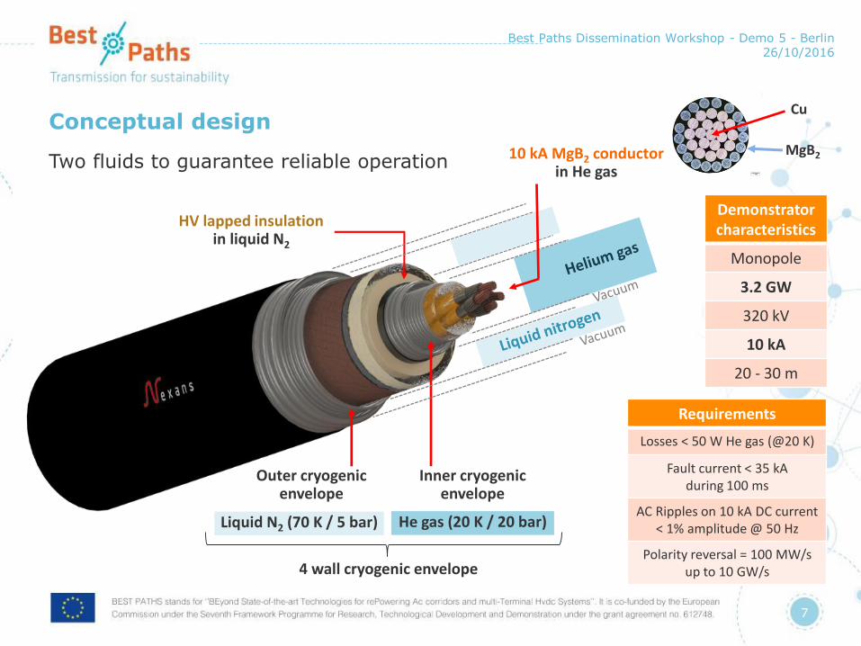
Conceptual design
Two fluids to guarantee reliable operation
Best Paths Dissemination Workshop - Demo 5 - Berlin 26/10/2016
7
10 kA MgB2 conductor in He gas
Outer cryogenic envelope
HV lapped insulationin liquid N2
Inner cryogenic envelope
4 wall cryogenic envelope
Liquid N2 (70 K / 5 bar) He gas (20 K / 20 bar)
Demonstrator characteristics
Monopole
3.2 GW
320 kV
10 kA
20 - 30 m
Requirements
Losses < 50 W He gas (@20 K)
Fault current < 35 kAduring 100 ms
AC Ripples on 10 kA DC current < 1% amplitude @ 50 Hz
Polarity reversal = 100 MW/sup to 10 GW/s
Cu
MgB2
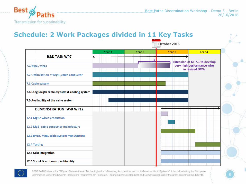
Schedule: 2 Work Packages divided in 11 Key Tasks
Best Paths Dissemination Workshop - Demo 5 - Berlin 26/10/2016
8
Extension of KT 7.1 to develop very high performance wire
in revised DOW
October 2016
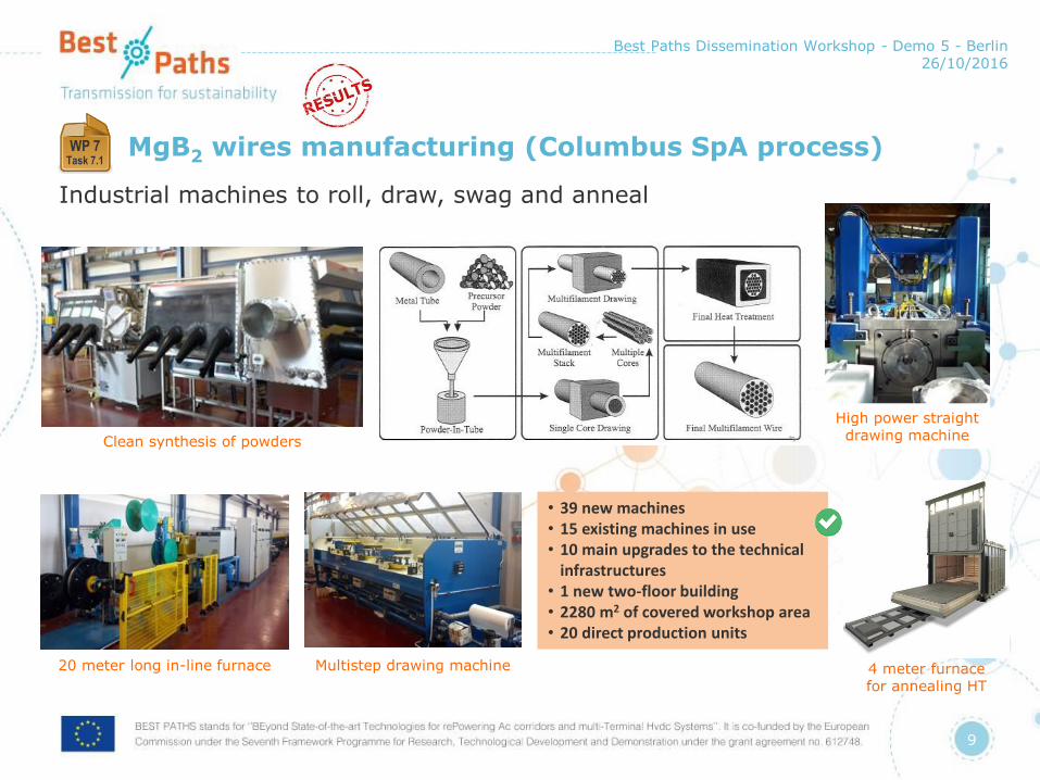
MgB2 wires manufacturing (Columbus SpA process)
Industrial machines to roll, draw, swag and anneal
Best Paths Dissemination Workshop - Demo 5 - Berlin 26/10/2016
9
Clean synthesis of powders
20 meter long in-line furnace Multistep drawing machine 4 meter furnacefor annealing HT
High power straightdrawing machine
WP 7Task 7.1
• 39 new machines• 15 existing machines in use• 10 main upgrades to the technical
infrastructures• 1 new two-floor building• 2280 m2 of covered workshop area• 20 direct production units
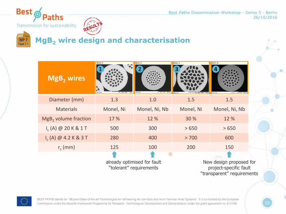
MgB2 wire design and characterisation
Best Paths Dissemination Workshop - Demo 5 - Berlin 26/10/2016
10
WP 7Task 7.1
MgB2 wires
Diameter (mm) 1.3 1.0 1.5 1.5
Materials Monel, Ni Monel, Ni, Nb Monel, Ni Monel, Ni, Nb
MgB2 volume fraction 17 % 12 % 30 % 12 %
Ic (A) @ 20 K & 1 T 500 300 > 650 > 650
Ic (A) @ 4.2 K & 3 T 280 400 > 700 600
rc (mm) 125 100 200 150
already optimised for fault “tolerant” requirements
New design proposed for project-specific fault
“transparent” requirements
❹❸❷❶
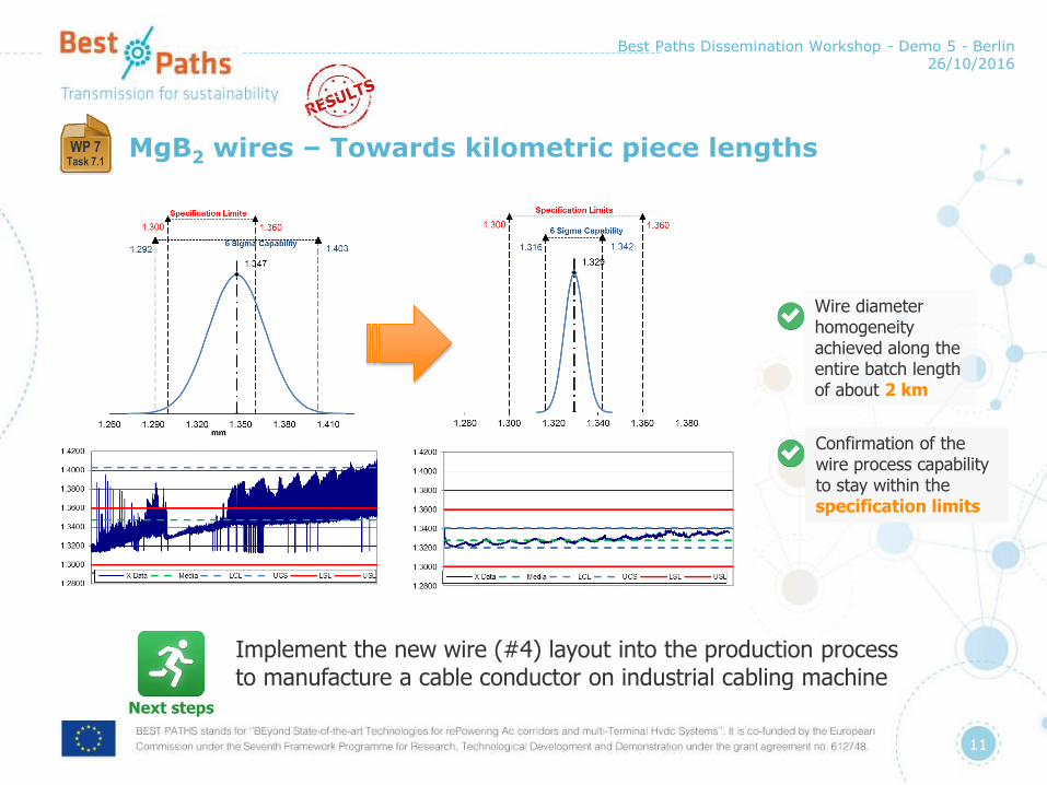
MgB2 wires – Towards kilometric piece lengths
Best Paths Dissemination Workshop - Demo 5 - Berlin 26/10/2016
11
WP 7Task 7.1
Next steps
Implement the new wire (#4) layout into the production process to manufacture a cable conductor on industrial cabling machine
11
Wire diameter homogeneity achieved along the entire batch length of about 2 km
Confirmation of the wire process capabilityto stay within the specification limits

10 kA MgB2 cable conductor
Best Paths Dissemination Workshop - Demo 5 - Berlin 26/10/2016
12
WP 7Task 7.2
Strategy 1: Control quenching during the fault
Cable already manufactured by Nexans
Measurements of extracted wires performed after cabling after bending on 1.2 m diameter drum by Columbus SPA show no degradation
Ongoing electrical characterization of cable prototypes at CERN:Measurements of the critical current of 2 meter long prototype cable tested in liquid (at 4.3 K) and gaseous helium (at temperatures between 15 K and 30 K)
Cu MgB2
18 MgB2 wiresIc = 14000 AIop/Ic = 0.72D= 9.6 mm
Modeling: transient phenomena(= thermal losses)
• Power inversion from 100 MW/s up to 10 GW/s
• Fault current: 35 kA during 100 ms
• Ripple losses due to current source into the MgB2 wire
But possible at 5 GW/s
Risk of quench identified at 10 GW/s ramp
Fault tolerant cable conductor design validated:• For the controlled quench cable design,
the temperature after a fault has been estimated (≈ 90 K)
• Time to recover ≈ several seconds
Ripples are acceptable:• 1 % 50 Hz ripples generate coupling
losses in the same order of magnitude as the cryo-envelop (0.1 W/m) manageable with the cooling system

10 kA MgB2 cable conductor
Best Paths Dissemination Workshop - Demo 5 - Berlin 26/10/2016
13
WP 7Task 7.2
• Several possible designs to accept current higher than 35 kA without quenches
• Possible by the unique properties of the MgB2 superconductor: high current and good stability at low cost
• With a maximum diameter of 20 mm to limit the losses of the inner cryogenic envelope (< 0.15 W/m)
Strategy 2: Fault transparent MgB2
cable configurations(=no quench during the fault)
MgB2 wires
Diameter (mm) 1.5
Design Simple stage
Cable diameter (mm) 19
Number of MgB2 wires 36
❹
Very high currents can be withstood within an acceptable cable size, when using the “fault transparent” design. This could save the power grid from a blackout.
Design and manufacture a mockup of a 10 kA cable conductor built with 9 to 12 wires #4 around a flexible copper core at Nexans
Electrical characterisation of cable prototypes at CERN and Columbus:• Measurements of the critical current of extracted
wires and 2-meter long “mockup” cable tested in liquid (at 4.3 K) and gaseous helium (at temperatures between 15 K and 30 K)
• Very high current expected Ic > 800 A at 20 K and 1 T for wire
• Ic > 35 kA!!! for cable conductorToo high to be measured
10 kA MgB2 cable conductor
Best Paths Dissemination Workshop - Demo 5 - Berlin 26/10/2016
14
WP 7Task 7.2
Next steps
1. Manufacture a cable conductor (Type 4) based on the results of wire 4 characterization and on the specifications from the modeling task
2. Measure the critical current of cable conductor (Type 1) (expected Ic ~ 14 kA)
3. Measure the critical current of a mockup cable conductor (Type 4) (expected Ic ~ 18 kA)

Cable system: termination
Best Paths Dissemination Workshop - Demo 5 - Berlin 26/10/2016
15
WP 7Task 7.3
High Voltage parts
For injection of:1. Cryogenic fluids He & Liq N2
2. Current
70 K flow (inlet/outlet)
Liquid nitrogen
Grounded parts
20 K flow (inlet/outlet)
Helium gas
Principle of HVDC termination
• Withstand the full testing voltage
• Should inject the current into the cable conductor with an hybrid current leads
• Should allow the Liq N2 cryogenic fluid injection
Height ≈ 8 m
Principle of CryogenicHV insulated line
• Withstand the full testing voltage
• Should allow the cryogenic fluid circulation (tightness / resistance to pressure 20 bar)
• Should have a good radial thermal insulation

Cable system: hybrid current leads
Best Paths Dissemination Workshop - Demo 5 - Berlin 26/10/2016
16
WP 7Task 7.3
Hybrid current leads benefit from high temperaturesuperconductor tapes
Welding tocable cryostat
(tightness 20 K)
20 K20 bar
cable cryostat
20 K – 77 KThermal insulated area / Low thermal
conduction area
High temperature superconductor tapes
Brazed connection to MgB2 cable
70 K5 barLN2
Transition 70 K - Ambient
not represented in this scheme
(copper rod is foreseen…)
Welding totermination cryostat
(tightness 70 K)
10 kA current
Total heat load expected per current
leads at 70-77 K500 W
Total heat load expected per current lead in He gas at 20 K
≈ 6 W
< 1 W calculated by KIT by FEM modeling
based on the design
In accordance with the calculation, prototype of current lead tested is able to transfer 10 kA at 77 K in Liq N2 in superconducting state.Ready for demonstration
Current leads are a heat inlet point within the system (Joule + thermal conduction)

Cable system: HV cable insulation
Best Paths Dissemination Workshop - Demo 5 - Berlin 26/10/2016
17
WP 7Task 7.3
A versatile and quick lapping line has been designed for preparation of short model 1 samples• Different tapes’ material (paper, PP, PPLP, etc…)• Different dimensions (thickness, width,…)• Different pitches and gaps between the tapes
HV cable insulation= lapped tapes impregnated with liquid nitrogen
Cryogenic HV testing equipment for space charge measurements close to operating conditions of the cable HV insulation was designed and is operational
Select the best equipment to limit the space charges in DC with the highest voltage breakdown
Commissioning of testing equipment for cable insulator is completed• Submitted up to 60 kV
(possible upgrade to 120 kV)• In LN2 under 5 bar pressure
with a slow fluid flow• Temperature regulation by
exchanger

Cable system
Best Paths Dissemination Workshop - Demo 5 - Berlin 26/10/2016
18
WP 7Task 7.3
HV cable insulation • 40 kV are applied across a 2 mm thick Kraft
paper impregnated with Liq N2
• A good elastic wave propagation through the sample is found
No trapped charge carrier is found
HV insulation made using paper impregnated with Liq N2 looks like a good candidate for HVDC superconducting cable
Next steps
1. Manufacture and test the cryogenic He injection tube
2. Manufacture HV cable samples with different lapping layouts
3. Verify the charge carrier distributions within the insulation to assess the insulation design with PPLP
4. Finalise cable HV insulation design (Paper or PPLP)
5. Design termination cryostat and bushing after definition of cable HV insulation
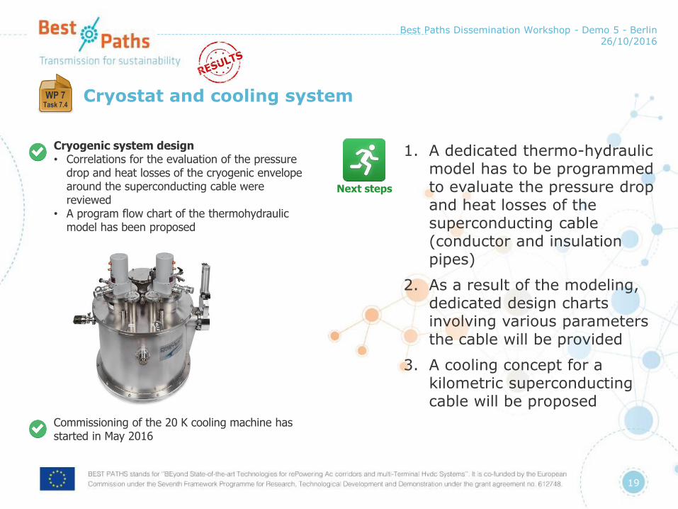
Cryostat and cooling system
Best Paths Dissemination Workshop - Demo 5 - Berlin 26/10/2016
19
WP 7Task 7.4
Cryogenic system design• Correlations for the evaluation of the pressure
drop and heat losses of the cryogenic envelope around the superconducting cable were reviewed
• A program flow chart of the thermohydraulicmodel has been proposed
Commissioning of the 20 K cooling machine has started in May 2016
Next steps
1. A dedicated thermo-hydraulic model has to be programmed to evaluate the pressure drop and heat losses of the superconducting cable (conductor and insulation pipes)
2. As a result of the modeling, dedicated design charts involving various parameters the cable will be provided
3. A cooling concept for a kilometric superconducting cable will be proposed

Availability of the system
Best Paths Dissemination Workshop - Demo 5 - Berlin 26/10/2016
20
WP 7Task 7.5
Concept designs of different systems• Conceptual design of the cooling system
including redundancy for a superconducting cable several kilometer long: a modular system keeping a temperature well where the cable lays down
• Radial inward heat flow is removed by a cooler at the end of each the cryostat module, which is filled by a cryo-fluid below 25 K
• Different thermal shields (liquid, gas or solid) are proposed to increase the availability of the system even during repairs or maintenance operation
Next steps
1. Selection of the best solutions based on the evaluation of the energy efficiency and cost estimation
2. According to the selection, redundancy strategies will be developed

Expected results and impact
Best Paths Dissemination Workshop - Demo 5 - Berlin 26/10/2016
21
1000
2000
Transmitted power (MW)
100 200 300 400
Voltage(kV)
3000
4000
5000
Eco-friendly Innovations in Electricity Transmission and Distribution Networks, Woodhead Publishing Series in Energy: Number 72; 2015 Edited by Jean-Luc Bessede P158
Best Paths Demo 5
Increased powerat a reduced voltage level
Reduced power transmission losses

Consequent reduction of raw materials
Best Paths Dissemination Workshop - Demo 5 - Berlin 26/10/2016
22
Copper 2000 mm² Conductor
Superconducting wires
MgB2
XLPE extruded cable
56 mm
1.1 mm
> 10 000 A
≈ 1 800 A
(One € coin)
Demo 5 conductor
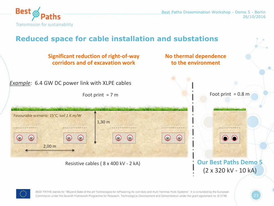
Reduced space for cable installation and substations
Best Paths Dissemination Workshop - Demo 5 - Berlin 26/10/2016
23
Significant reduction of right-of-way corridors and of excavation work
No thermal dependence to the environment
Example: 6.4 GW DC power link with XLPE cables
1,30 m
2,00 m
Foot print = 7 m
Resistive cables ( 8 x 400 kV - 2 kA)
Foot print = 0.8 m
Our Best Paths Demo 5(2 x 320 kV - 10 kA)
0
Favourable scenario: 15°C, soil 1 K.m/W

Recent DEMO 5 conference presentations
Best Paths Dissemination Workshop - Demo 5 - Berlin 26/10/2016
24
Date Presentation Title Meeting
May 2016An MgB2 superconducting cable for very high DC power transmission
16th IERE General Meeting & China Forum
July 2016Space charge measurements at very low temperatures
International Conference on Dielectrics (ICD)
August 2016An MgB2 superconducting cable for very high DC power transmission
Cigré Session 2016
September 2016
Midterm update on the high-power MgB2
DC superconducting cable project within BEST PATHS
27th Applied Superconductivity
Conference (ASC 2016)
September 2016
MgB2 round wires for the high power superconducting cable demonstrator in the Best Paths project
27th Applied Superconductivity
Conference (ASC 2016)
November 2016
Numerical model for quench calculations in a 10 kA MgB2 superconducting cable
17th Conference on Electromagnetic Field
Computation (CEFC 2016)

DEMO 5 publications in 2016
Best Paths Dissemination Workshop - Demo 5 - Berlin 26/10/2016
25
Date Publication Title Journal
March 2016An MgB2 HVDC superconducting cable for power transmission with a reduced carbon footprint (Invited)
Proceedings of the ED2E Conference
April 2016The BEST PATHS Project on MgB2
Superconducting Cables for Very High Power Transmission
IEEE Transactions onApplied
Superconductivity
April 2016 3-D Numerical Modeling of AC Losses in Multifilamentary MgB2 Wires (Invited)
IEEE Transactions onApplied Supercond.
June 2016Space charge measurements at very low temperatures
Proceedings of the International Conference
on Dielectrics (ICD)
August 2016 An MgB2 superconducting cable for very high DC power transmission
Proceedings of the Cigré Session 2016
September 2016
Midterm update on the high-power MgB2
DC superconducting cable project within BEST PATHS (Under peer review)
IEEE Transactions onApplied
Superconductivity
Conclusion: Highlights and critical issues
A good momentum of the team is now achieved
Exciting collaborative works are carried out within the Demo 5 teams
1. Demo 5 is very innovative and based on systems to be developed
2. Difficulties to measure the performances of the MgB2 wires (Ic, losses..) or testing high voltage at cryogenic temperatures.
Limited number of experimental set-ups available but collaborations beyond the Best Paths consortium are started (IEC TC 90, Cigré, universities, etc…)
3. Conceptual design of the critical parts is now validated
No blocking point has been identified so far
4. In 2017 the project will enter a new phase, the demonstration, which will require significant engineering developments…
Best Paths Dissemination Workshop - Demo 5 - Berlin 26/10/2016
26

Contacts
• Christian-Eric BRUZEK
• Adela MARIAN
• Frédéric LESUR
Best Paths Dissemination Workshop - Demo 5 - Berlin 26/10/2016
27
www.bestpaths-project.eu
Follow us on @BestPaths_eu